ag gcs300 and gcs400 agricultural grade control system
TRANSCRIPT

Version 2.50Revision A
Part Number 58595-00-ENGSeptember 2006F
AG GCS300 and GCS400Agricultural Grade Control
SystemInstallation Manual

Contact InformationTrimble Geomatics and Engineering Division5475 Kellenburger RoadDayton, Ohio 45424-1099USA800-538-7800 (toll free in USA)+1-937-245-5600 Phone+1-937-233-9004 Fax www.trimble.comCopyright and Trademarks © 2000–2006, Caterpillar Trimble Control Technologies LLC. All rights reserved.Trimble and SiteVision are trademarks of Trimble Navigation Limited, registered in the United States Patent and Trademark Office and other countries.All other trademarks are the property of their respective owners.Release NoticeThis is the September 2006 release (Revision A) of the GCS300, GCS400, GCS500 and GCS600 Installation Manual, part number 58595-00-ENG. It applies to version 2.50 of the AG GCS300 and GCS400 Agricultural Grade Control System software.Product Warranty InformationFor warranty information, please refer to the Warranty Card included with this Trimble product, or consult your Trimble dealer.END-USER LICENSE AGREEMENT FOR EMBEDDED SOFTWARE/FIRMWAREIMPORTANT, READ CAREFULLY. THIS END USER LICENSE AGREEMENT ("AGREEMENT") IS A LEGAL AGREEMENT BETWEEN YOU AND TRIMBLE NAVIGATION LIMITED and applies to the computer software embedded within the Trimble product ("Device") purchased by you (whether built into hardware circuitry as firmware, embedded in flash memory or a PCMCIA card, or stored on magnetic or other media) ("Software"). This Agreement will also apply to any Software error corrections, updates and upgrades subsequently furnished by Trimble, unless such are accompanied by different license terms and conditions which will govern their use. The Software is protected by copyright laws and international copyright treaties, as well as other intellectual property laws and treaties. The Software is licensed, not sold. All rights reserved.BY CLICKING "YES" OR "I ACCEPT" IN THE ACCEPTANCE BOX, OR BY INSTALLING, COPYING OR OTHERWISE USING THE SOFTWARE, AS APPLICABLE, YOU AGREE TO BE BOUND BY THE TERMS OF THIS AGREEMENT. IF YOU DO NOT AGREE TO THE TERMS OF THIS AGREEMENT, DO NOT USE THE DEVICE OR COPY THE SOFTWARE. INSTEAD, PROMPTLY RETURN THE UNUSED SOFTWARE AND DEVICE TO THE PLACE FROM WHICH YOU OBTAINED THEM FOR A REFUND. ANY USE OF THE SOFTWARE, INCLUDING, BUT NOT LIMITED TO USE ON THE DEVICE, WILL CONSTITUTE YOUR AGREEMENT TO THIS AGREEMENT (OR RATIFICATION OF ANY PREVIOUS CONSENT).1 SOFTWARE PRODUCT LICENSE1.1 License Grant. Subject to the terms and conditions of this Agreement, Trimble grants you a non-exclusive right to use one copy of the Software in machine-readable form only on the Device. Such use is limited to use with the Device for which it was intended and into which it was embedded. You may use the installation Software from a computer solely to download the Software to one Device. In no event shall the installation
Software be used to download the Software onto more than one Device. A license for the Software may not be shared or used concurrently on different computers or Devices. 1.2 Other Rights and Limitations. (1) You may not copy, modify, make derivative works of, rent, lease, sell, distribute or transfer the Software, in whole or in part, except as otherwise expressly authorized under this Agreement, and you agree to use all commercially reasonable efforts to prevent its unauthorized use and disclosure. (2) The Software contains valuable trade secrets proprietary to Trimble and its licensors. To the extent permitted by relevant law, you shall not, nor allow any third party to copy, decompile, disassemble or otherwise reverse engineer the Software, or attempt to do so, provided, however, that to the extent any applicable mandatory laws give you the right to perform any of the aforementioned activities without Trimble's consent in order to gain certain information about the Software for purposes specified in the respective statutes (e.g., interoperability), you hereby agree that, before exercising any such rights, you shall first request such information from Trimble in writing detailing the purpose for which you need the information. Only if and after Trimble, at its sole discretion, partly or completely denies your request, may you exercise such statutory rights. (3) You may permanently transfer all of your rights under this Agreement only as part of a permanent sale or transfer of the Device, provided you retain no copies, you transfer all of the Software (including all component parts, the media and printed materials, any upgrades, and this Agreement) and the recipient agrees to the terms of this Agreement. If the Software portion is an upgrade, any transfer must include all prior versions of the Software. (4) You may not use the Software for performance, benchmark or comparison testing or analysis, or disclose to any third party or release any results thereof (all of which information shall be considered Trimble confidential information) without Trimble's prior written consent of Trimble. (5) You may not directly or indirectly export or re-export, or knowingly permit the export or re-export of the Software (or portions thereof) to any country, or to any person or entity subject to United States or foreign export restrictions in contravention of such laws and without first obtaining appropriate licenses; and (6) You acknowledge that the Software and underlying technology subject to U.S. Export jurisdiction. You agree to comply with all applicable international and national laws that apply to the Software and underlying technology, including U.S. Export Administration Regulations, as well as end-user, end-use and destination restrictions issued by U.S. and other governments. 1.3 Termination. You may terminate this Agreement by ceasing all use of the Software. Without prejudice as to any other rights, Trimble may terminate this Agreement without notice if you fail to comply with the terms and conditions of this Agreement. In either event, you must destroy all copies of the Software and all of its component parts.1.4 Copyright. All title and copyrights in and to the Software (including but not limited to any images, photographs, animations, video, audio, music, and text incorporated into the Software), the accompanying printed materials, and any copies of the Software are owned by Trimble and its licensors. You shall not remove, cover or alter any of Trimble's patent, copyright or trademark notices placed upon, embedded in or displayed by the Software or on its packaging and related materials. 1.5 U.S. Government Restricted Rights. The Software is provided with "RESTRICTED RIGHTS." Use, duplication, or disclosure by the United States Government is subject to

restrictions as set forth in this Agreement, and as provided in DFARS 227.7202-1(a) and 227.7202-3(a) (1995), DFARS 252.227-7013(c)(1)(ii) (OCT 1988), FAR 12.212(a) (1995), FAR 52.227-19, or FAR 52.227-14(ALT III), as applicable.2 LIMITED WARRANTY. The limited warranty applicable to the Software (inclusive of all warranty exclusions and disclaimers) shall be as set forth in the limited warranty provided with the Device. Trimble does not warrant the Software separately from the Device. Likewise, the applicable limited warranty does not apply to error corrections, updates or upgrades of the Software after expiration of the limited warranty period, which, if provided, are provided "AS IS" and without warranty unless otherwise specified in writing by Trimble. Because the Software is inherently complex and may not be completely free of nonconformities, defects or errors, you are advised to verify your work. Trimble does not warrant that the Software will operate error free or uninterrupted, will meet your needs or expectations, or that all nonconformities can or will be corrected. 3 GENERAL.3.1 This Agreement shall be governed by the laws of the State of California and applicable United States Federal law without reference to "conflict of laws" principles or provisions. The United Nations Convention on Contracts for the International Sale of Goods will not apply to this Agreement. Jurisdiction and venue of any dispute or court action arising from or related to this Agreement or the Software shall lie exclusively in or be transferred to the courts the County of Santa Clara, California, and/or the United States District Court for the Northern District of California. You hereby consent and agree not to contest, such jurisdiction, venue and governing law. 3.2 Section 3.1 notwithstanding, if you acquired the Device in Canada, this Agreement is governed by the laws of the Province of Ontario, Canada. In such case each of the parties to this Agreement irrevocably attorns to the jurisdiction of the courts of the Province of Ontario and further agrees to commence any litigation that may arise under this Agreement in the courts located in the Judicial District of York, Province of Ontario. If you acquired the Device in the European Union, this Agreement is governed by the laws of The Netherlands, excluding its rules governing conflicts of laws and excluding the United Nations Convention on the International Sale of Goods. In such case each of the parties to this Agreement irrevocably attorns to the jurisdiction of the courts of Netherlands and further agrees to commence any litigation that may arise under this Agreement in the courts of The Hague, Netherlands.3.3 Trimble reserves all rights not expressly granted by this Agreement3.4 Official Language. The official language of this Agreement and of any documents relating thereto is English. For purposes of interpretation, or in the event of a conflict between English and versions of this Agreement or related documents in any other language, the English language version shall be controlling.
NoticesClass B Statement – Notice to Users. This equipment has been tested and found to comply with the limits for a Class B digital device, pursuant to Part 15 of the FCC rules. These limits are designed to provide reasonable protection against harmful interference in a residential installation. This equipment generates, uses, and can radiate radio frequency energy and, if not installed and used in accordance with the instructions, may cause harmful interference to radio communication. However, there is no guarantee that interference will not occur in a particular installation. If this equipment does cause harmful interference to radio or
television reception, which can be determined by turning the equipment off and on, the user is encouraged to try to correct the interference by one or more of the following measures:
– Reorient or relocate the receiving antenna.– Increase the separation between the equipment and the
receiver.– Connect the equipment into an outlet on a circuit different
from that to which the receiver is connected.– Consult the dealer or an experienced radio/TV technician
for help.
Changes and modifications not expressly approved by the manufacturer or registrant of this equipment can void your authority to operate this equipment under Federal Communications Commission rules.
CanadaThis digital apparatus does not exceed the Class B limits for radio noise emissions from digital apparatus as set out in the radio interference regulations of the Canadian Department of Communications.Le présent appareil numérique n’émet pas de bruits radioélectriques dépassant les limites applicables aux appareils numériques de Classe B prescrites dans le règlement sur le brouillage radioélectrique édicté par le Ministère des Communications du Canada.This Class B digital apparatus complies with Canadian ICES-003.Cet appareil numérique de la classe B est conforme à la norme NMB-003 du Canada.
EuropeThis product has been tested and found to comply with the requirements for a Class B device pursuant to European Council Directive 89/336/EEC on EMC, thereby satisfying the requirements for CE Marking and sale within the European Economic Area (EEA). Contains Infineon radio module ROK 104001. These requirements are designed to provide reasonable protection against harmful interference when the equipment is operated in a residential or commercial environment.
Australia and New ZealandThis product conforms with the regulatory requirements of the Australian Communications Authority (ACA) EMC framework, thus satisfying the requirements for C-Tick Marking and sale within Australia and New Zealand.
Taiwan – Battery Recycling RequirementsThe product contains a removable Lithium-ion battery. Taiwanese regulations require that waste batteries are recycled.
Notice to Our European Union CustomersFor product recycling instructions and more information, please go to www.trimble.com/environment/summary.html. Recycling in Europe: To recycle Trimble WEEE (Waste Electrical and Electronic Equipment, products that run on electrical power.), Call +31 497 53 24 30, and ask for the "WEEE Associate". Or, mail a request for recycling instructions to:Trimble Europe BVc/o Menlo Worldwide LogisticsMeerheide 455521 DZ Eersel, NL


Contents1 Introduction
1.1 Introduction . . . . . . . . . . . . . . . . . . . . . . . . . . . . 2
1.2 Claim for Damage in Shipment . . . . . . . . . . . . . . . . . . 2
1.3 Technical Assistance . . . . . . . . . . . . . . . . . . . . . . . 2
1.4 Your Comments . . . . . . . . . . . . . . . . . . . . . . . . . . 3
1.5 Warnings . . . . . . . . . . . . . . . . . . . . . . . . . . . . . . 3
2 Pre-Installation2.1 Introduction . . . . . . . . . . . . . . . . . . . . . . . . . . . . 6
2.2 Pre-installation Site Visit and Machine Inspection . . . . . . . . 6
2.2.1 Pressurized items . . . . . . . . . . . . . . . . . . . . 7
2.2.2 Mounting and dismounting . . . . . . . . . . . . . . . 8
2.2.3 Hot fluids . . . . . . . . . . . . . . . . . . . . . . . . 8
2.2.4 Lockout . . . . . . . . . . . . . . . . . . . . . . . . . 8
2.3 Pre-installation Requirements . . . . . . . . . . . . . . . . . . . 9
2.3.1 Tools . . . . . . . . . . . . . . . . . . . . . . . . . . . 11
2.4 Operational Considerations . . . . . . . . . . . . . . . . . . . . 12
2.4.1 Safety . . . . . . . . . . . . . . . . . . . . . . . . . . 12
2.4.2 Ergonomics . . . . . . . . . . . . . . . . . . . . . . . 12
AG GCS300 and GCS400 Agricultural Grade Control System Installation Manual v

Contents
2.5 Environmental Considerations . . . . . . . . . . . . . . . . . . . 13
2.5.1 Shock and vibration . . . . . . . . . . . . . . . . . . . 13
2.5.2 Temperature . . . . . . . . . . . . . . . . . . . . . . . 13
2.5.3 Dust . . . . . . . . . . . . . . . . . . . . . . . . . . . 14
2.5.4 Water . . . . . . . . . . . . . . . . . . . . . . . . . . . 14
3 AG GCS300 and GCS400 System Installation3.1 Introduction . . . . . . . . . . . . . . . . . . . . . . . . . . . . 16
3.2 John Deere . . . . . . . . . . . . . . . . . . . . . . . . . . . . . 18
3.2.1 Ag GCS300 and GCS400 system harness . . . . . . . . 18
3.2.2 CB415 display box. . . . . . . . . . . . . . . . . . . . 18
3.2.3 PM400 power module . . . . . . . . . . . . . . . . . . 20
3.2.4 VM415 valve module . . . . . . . . . . . . . . . . . . 21
3.2.5 Valve connection . . . . . . . . . . . . . . . . . . . . . 24
3.2.6 Quick disconnect bracket . . . . . . . . . . . . . . . . 25
3.2.7 Mast mounting . . . . . . . . . . . . . . . . . . . . . . 25
3.2.8 System configuration . . . . . . . . . . . . . . . . . . 26
3.2.9 John Deere calibration . . . . . . . . . . . . . . . . . . 27
3.2.10 Calibration procedure . . . . . . . . . . . . . . . . . . 27
3.2.11 John Deere 30 Series calibration. . . . . . . . . . . . . 32
3.2.12 Calibration procedure . . . . . . . . . . . . . . . . . . 32
3.2.13 Clear faults in tractor. . . . . . . . . . . . . . . . . . . 33
3.2.14 Ag GCS300 and GCS400 valve calibration . . . . . . . 34
3.3 Case MX Series . . . . . . . . . . . . . . . . . . . . . . . . . . 35
3.3.1 Ag GCS300 and GCS400 system harness . . . . . . . . 35
3.3.2 CB415 display box. . . . . . . . . . . . . . . . . . . . 35
3.3.3 PM400 power module . . . . . . . . . . . . . . . . . . 36
3.3.4 VM415 valve module . . . . . . . . . . . . . . . . . . 38
3.3.5 Valve connection . . . . . . . . . . . . . . . . . . . . . 40
3.3.6 Quick disconnect bracket . . . . . . . . . . . . . . . . 42
vi AG GCS300 and GCS400 Agricultural Grade Control System Installation Manual

Contents
3.3.7 Mast mounting . . . . . . . . . . . . . . . . . . . . . . 42
3.3.8 System configuration . . . . . . . . . . . . . . . . . . 43
3.3.9 Calibration . . . . . . . . . . . . . . . . . . . . . . . . 44
3.3.10 MX Series fault / error codes . . . . . . . . . . . . . . 46
3.3.11 Error codes associated with the Ag GCS300 and GCS400 interface . . . . . . . . . . . . . . . . . . 47
3.3.12 Auxiliary auto mode switch . . . . . . . . . . . . . . . 47
3.3.13 System calibration procedure . . . . . . . . . . . . . . 49
3.4 Case STX Series . . . . . . . . . . . . . . . . . . . . . . . . . . 49
3.4.1 Ag GCS300 and GCS400 system harness . . . . . . . . 49
3.4.2 CB415 display box. . . . . . . . . . . . . . . . . . . . 49
3.4.3 PM400 power module . . . . . . . . . . . . . . . . . . 51
3.4.4 VM415 valve module . . . . . . . . . . . . . . . . . . 52
3.4.5 Quick disconnect bracket . . . . . . . . . . . . . . . . 54
3.4.6 Mast mounting . . . . . . . . . . . . . . . . . . . . . . 55
3.4.7 Power connection . . . . . . . . . . . . . . . . . . . . 56
3.4.8 Valve connection . . . . . . . . . . . . . . . . . . . . . 56
3.4.9 System configuration . . . . . . . . . . . . . . . . . . 57
3.4.10 Case STX tractor configuration . . . . . . . . . . . . . 58
3.4.11 Case STX fault / error codes . . . . . . . . . . . . . . . 60
3.4.12 Error codes associated with the Ag GCS300 and GCS400 interface . . . . . . . . . . . . . . . . . . 61
3.4.13 Auxiliary auto mode switch . . . . . . . . . . . . . . . 61
3.4.14 System calibration procedure . . . . . . . . . . . . . . 62
3.5 Challenger MT Series . . . . . . . . . . . . . . . . . . . . . . . 62
3.5.1 Machine validation. . . . . . . . . . . . . . . . . . . . 63
3.5.2 Ag GCS300 and GCS400 system harness . . . . . . . . 67
3.5.3 CB415 display box. . . . . . . . . . . . . . . . . . . . 68
3.5.4 PM400 power module . . . . . . . . . . . . . . . . . . 68
3.5.5 Installing the Challenger direct connect cable . . . . . . 71
3.5.6 Quick disconnect assembly . . . . . . . . . . . . . . . 74
AG GCS300 and GCS400 Agricultural Grade Control System Installation Manual vii

Contents
3.5.7 Mast mounting . . . . . . . . . . . . . . . . . . . . . . 74
3.5.8 System calibration procedure . . . . . . . . . . . . . . 75
4 Ag GCS300 and GCS400 Remote Switch Box4.1 Introduction . . . . . . . . . . . . . . . . . . . . . . . . . . . . 78
4.2 Trimble Remote Switch Box . . . . . . . . . . . . . . . . . . . . 78
4.2.1 Switch box mounting . . . . . . . . . . . . . . . . . . 79
4.3 Local Remote Switch Box . . . . . . . . . . . . . . . . . . . . . 80
5 AG GCS300 and GCS400 Non-Direct Connect Agricultural Machine Installation5.1 Introduction . . . . . . . . . . . . . . . . . . . . . . . . . . . . 82
5.2 Danfoss Valve Hydraulics . . . . . . . . . . . . . . . . . . . . . 82
5.2.1 Danfoss valve wiring. . . . . . . . . . . . . . . . . . . 84
5.2.2 PT valve wiring . . . . . . . . . . . . . . . . . . . . . 85
6 Machine Measurement Techniques6.1 Introduction . . . . . . . . . . . . . . . . . . . . . . . . . . . . 90
6.2 Measurement Techniques . . . . . . . . . . . . . . . . . . . . . 90
6.2.1 Blade width . . . . . . . . . . . . . . . . . . . . . . . 90
A Technical SpecificationsA.1 Introduction . . . . . . . . . . . . . . . . . . . . . . . . . . . . 94
A.2 System Interconnections . . . . . . . . . . . . . . . . . . . . . . 94
A.2.1 Main cable harness. . . . . . . . . . . . . . . . . . . . 95
A.2.2 CB415 display cable . . . . . . . . . . . . . . . . . . . 96
A.2.3 PM400 power cable . . . . . . . . . . . . . . . . . . . 97
A.2.4 LR400/LR410 coil connector cable (EM400) . . . . . . 98
A.2.5 Trimble remote switch box assembly . . . . . . . . . . 99
A.2.6 Elevation quick control cable . . . . . . . . . . . . . . 100
vii i AG GCS300 and GCS400 Agricultural Grade Control System Installation Manual

Contents
A.2.7 EM400 terminated control cable. . . . . . . . . . . . . 101
A.2.8 EM400 Y-control cable . . . . . . . . . . . . . . . . . 102
A.2.9 SR300 terminated control cable . . . . . . . . . . . . . 103
A.2.10 SR300 Y-control cable . . . . . . . . . . . . . . . . . . 104
A.3 Component Connectors . . . . . . . . . . . . . . . . . . . . . . 106
A.3.1 Elevation sensor connector . . . . . . . . . . . . . . . 107
A.3.2 Elevation sensor quick disconnect socket . . . . . . . . 108
A.3.3 PM400 power module . . . . . . . . . . . . . . . . . . 109
A.3.4 VM410 valve module . . . . . . . . . . . . . . . . . . 110
A.3.5 VM415 valve module . . . . . . . . . . . . . . . . . . 111
A.3.6 VM420 valve module . . . . . . . . . . . . . . . . . . 112
A.3.7 AS400 angle sensor . . . . . . . . . . . . . . . . . . . 113
A.3.8 EM400 electric mast connectors . . . . . . . . . . . . . 114
A.3.9 LR400 and LR410 laser receivers . . . . . . . . . . . . 115
A.3.10 SR300 receiver mast . . . . . . . . . . . . . . . . . . . 116
A.3.11 CB415 connectors . . . . . . . . . . . . . . . . . . . . 117
A.4 Component Electrical and Thermal Specifications . . . . . . . . 119
A.4.1 PM400 power module . . . . . . . . . . . . . . . . . . 120
A.4.2 VM410 valve module . . . . . . . . . . . . . . . . . . 120
A.4.3 VM415 valve module . . . . . . . . . . . . . . . . . . 121
A.4.4 VM420 valve module . . . . . . . . . . . . . . . . . . 121
A.4.5 EM400 electric mast . . . . . . . . . . . . . . . . . . . 122
A.4.6 SR300 receiver mast . . . . . . . . . . . . . . . . . . . 122
A.4.7 LR400 laser receiver . . . . . . . . . . . . . . . . . . . 123
A.4.8 LR410 laser receiver . . . . . . . . . . . . . . . . . . . 124
A.4.9 AS400 angle sensor . . . . . . . . . . . . . . . . . . . 124
A.4.10 SA400 single adaptor . . . . . . . . . . . . . . . . . . 125
A.4.11 CB415 dual control box . . . . . . . . . . . . . . . . . 125
AG GCS300 and GCS400 Agricultural Grade Control System Installation Manual ix
Contents
B System MaintenanceB.1 Introduction . . . . . . . . . . . . . . . . . . . . . . . . . . . . 128
B.2 General Maintenance Procedures . . . . . . . . . . . . . . . . . 128
Index
x AG GCS300 and GCS400 Agricultural Grade Control System Installation Manual

C H A P T E R
1
Introduction 1In this chapter:
Introduction
Claim for Damage in Shipment
Technical Assistance
Your Comments
Warnings

1 Introduction
1.1 IntroductionWelcome to the AG GCS300 and GCS400 Agricultural Grade Control System Installation Manual. This manual describes how to install the AG GCS300 and GCS400 Grade Control System (the system). The system is a rugged and reliable machine control system that is field-proven and versatile. The system simplifies leveling and drainage applications, increases accuracy, and saves time.
This manual provides instructions for installing the system on agricultural applications such as single, tandem, dual split-axle scrapers. This manual is for installation personnel.
For more information about system operation, refer to the AG GCS300 and GCS400 Agricultural Grade Control System Operator’s Manual.
For information about how to configure the system or about upgrading the system, refer to the AG GCS300 and GCS400 Agricultural Grade Control System Reference Manual.
1.2 Claim for Damage in Shipment Trimble recommends that you inspect your package(s) for possible damage when they are received. The equipment has been packaged for safe delivery. However, in the unlikely event that damage has occurred, immediately file a claim with the carrier or, if insured separately, with the insurance company.
1.3 Technical Assistance If you have a problem and cannot find the information you need in the product documentation, contact your Trimble dealer.
2 AG GCS300 and GCS400 Agricultural Grade Control System Installation Manual
Introduction 1
1.4 Your Comments Feedback about the documentation helps us to improve the documentation with each revision. To send feedback, e-mail your comments to [email protected].
1.5 Warnings
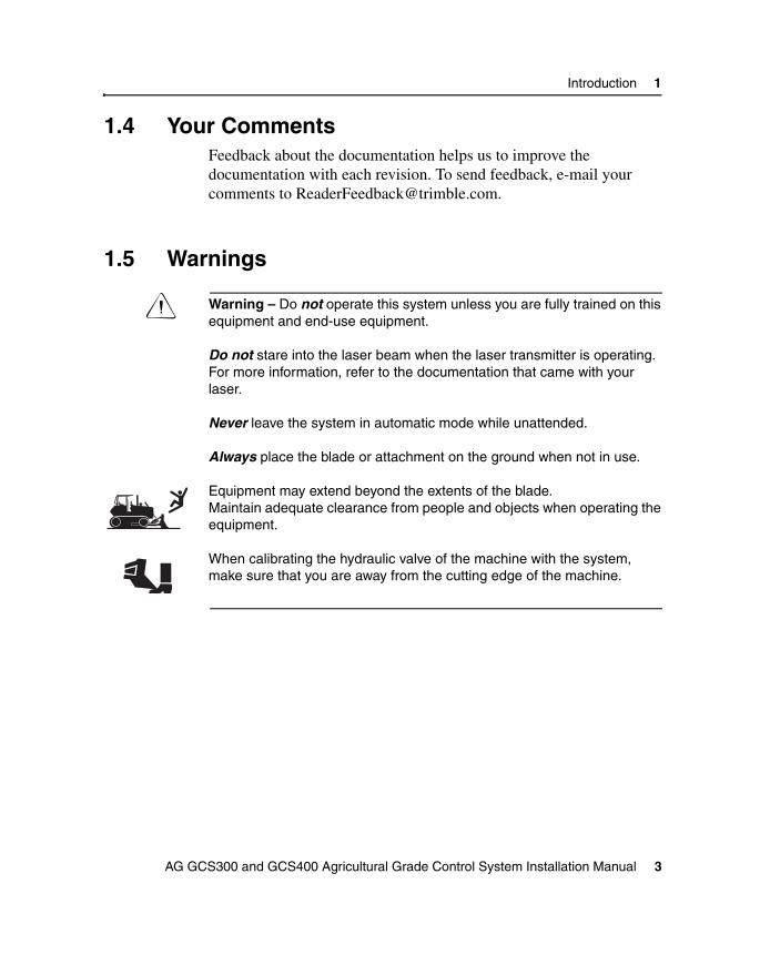
C Warning – Do not operate this system unless you are fully trained on this equipment and end-use equipment.
Do not stare into the laser beam when the laser transmitter is operating. For more information, refer to the documentation that came with your laser.
Never leave the system in automatic mode while unattended.
Always place the blade or attachment on the ground when not in use.
Equipment may extend beyond the extents of the blade.Maintain adequate clearance from people and objects when operating the equipment.
When calibrating the hydraulic valve of the machine with the system, make sure that you are away from the cutting edge of the machine.
AG GCS300 and GCS400 Agricultural Grade Control System Installation Manual 3

1 Introduction
4 AG GCS300 and GCS400 Agricultural Grade Control System Installation Manual

C H A P T E R
2
Pre-Installation 2In this chapter:
Introduction
Pre-installation Site Visit and Machine Inspection
Pre-installation Requirements
Operational Considerations
Environmental Considerations

2 Pre-Installation
2.1 IntroductionThis chapter describes the pre-installation considerations. For specific information about how to configure the system, refer to the AG GCS300 and GCS400 Agricultural Grade Control System Reference Manual (PN 60513-00-ENG).
2.2 Pre-installation Site Visit and Machine Inspection
Trimble strongly recommends that you visit the installation site for a pre-installation check. Check all aspects of the installation in advance, so that you save valuable time later.
Before and during installation, you will need to discuss aspects of the installation with people on the site, such as the equipment owner, contractor, or machine operators.
When on the site:
• Identify the machine on which the system is to be installed.
Get agreement that the system is to be installed on a specific machine.
• Make sure that the machine meets specification, so that the system can perform properly.
• Decide on the routing of cables and the placement of equipment.
Try to get agreement on the positioning of the system components.
• Identify any brackets needed for the specific machine.
Take measurements and get the brackets made ahead of time.
B Tip – Use some cardboard and tape to make a template for any additional brackets.
6 AG GCS300 and GCS400 Agricultural Grade Control System Installation Manual
Pre-Installation 2
• Identify where the installation is to take place.
If possible, install the equipment in a fully equipped workshop and steam clean the machine before you start.
B Tip – Arrange to install the equipment while the machine is being serviced. Experienced mechanics will be available to help you.
• Schedule the people and equipment required for the installation.
Make sure that a welder is available, and that the welder knows the size of plate to be welded.
• With the service mechanic, decide on the method of mounting the equipment and routing cables. In the future, this mechanic will service the system.
2.2.1 Pressurized items
Relieve all pressure in oil, air, or water systems before any lines, fittings, or related items are disconnected or removed.
C Warning – Important Safety Information for Working on Mobile Hydraulics:Always wear protective glasses, protective shoes, and other protective equipment as required by job conditions and machines. In particular, wear protective glasses when using pressurized air to clean surfaces, or cleaning overhead areas.Do not wear loose clothing or jewelry that can catch on machine parts or tools.
AG GCS300 and GCS400 Agricultural Grade Control System Installation Manual 7

2 Pre-Installation
It is recommended to ensure the machine and implement is pressure washed of dirt and possible contaminants which may pose a potential safety or health risk to the installer.
2.2.2 Mounting and dismounting
Use steps and handrails when mounting or dismounting a machine, facing the machine.
2.2.3 Hot fluids
To avoid burns, be alert for hot parts and hoses on machines. Be careful when removing fill caps, breathers, and hose connections on the machine.
2.2.4 Lockout
Before starting to disconnect hydraulic and electrical components, disconnect the battery cable and attach a “Do Not Operate” or similar tag in the operator’s compartment. A lockout box should be locked onto the battery terminal to avoid the battery from being reconnected and the machine possibly started.
If possible, make all modifications to the machine parked on a level, hard surface. Block the wheels to prevent rolling while working on or under the machine.
8 AG GCS300 and GCS400 Agricultural Grade Control System Installation Manual

Pre-Installation 2
2.3 Pre-installation RequirementsThis section describes the pre-installation bench test, and the tools required to install the equipment on a machine. Before installing the equipment, connect it and check that all components are present.
When installing the equipment on a machine, Trimble recommends that the system components be connected and tested to ensure a successful installation. After connecting the system harness and electrical connections, use the following guidelines when checking the system:
Note – Refer to the supplied GCS system electrical diagram for proper connectivity.
1. Ensure the connected components appear in the CB415 guidance screen. For more information about the guidance screen icons, refer to the AG GCS300 and GCS400 Agricultural Grade Control System Reference Manual (PN 60513-00-ENG).
2. Ensure there are no faults or warnings appearing on the CB415 display screen. If fault messages appear, acknowledge the message and enter the diagnostics menu for more information regarding the fault messages. For information about accessing the Diagnotics menu, refer to the AG GCS300 and GCS400 Agricultural Grade Control System Reference Manual (PN 60513-00-ENG).
3. Function test the components for operation. This includes operation of masts, sonic tracers, laser receivers, and sensors.
Figure 2.1 shows a diagram of a system with all available devices shown.
AG GCS300 and GCS400 Agricultural Grade Control System Installation Manual 9

2 Pre-Installation
Figure 2.1 AG GCS300 and GCS400 system overview
A CB415 displayB CB415 harness assemblyC PM400 power moduleD PM400 power cableE VM415 valve module
F Valve cableG Connector to elevation deviceH CAN terminator
VM42
0
VM42
0
A
D F
C E
BG
H
*Cable connection is used on Challenger
10 AG GCS300 and GCS400 Agricultural Grade Control System Installation Manual
Pre-Installation 2
2.3.1 Tools
During the pre-installation check, identify the tools needed to attach the equipment to the machine. Make sure these tools are available.
The recommended tools are:
• a multimeter for checking power
• RTV silicone sealer (to seal any cable entry holes)
• cable ties
• a piece of pipe or wire to feed cables through the machine
• blue Loctite 262 (Trimble PN 33803) and anti-seize compound
• a 11⁄8 inch box/open end wrench
• SAE and metric socket wrenches
• assorted open and box end wrenches
• assorted screws, allen and torque drivers
• Deutsch crimp tool (Trimble PN 5401-1568)
• torque wrench
• a portable drill, drill bits, and hole saws
• torque drivers and diagonal cutters
• wire strippers and pliers
• high quality electrical tape and heat shrink tubing
• a step ladder
• a steel tape or rule calibrated in the units of measurement used to measure the machine
Also, start planning the installation of the cables on the machine. Consider the following items:
• length of the planned cable route
• ease of feeding cables and connectors through the machine
AG GCS300 and GCS400 Agricultural Grade Control System Installation Manual 11

2 Pre-Installation
2.4 Operational ConsiderationsWhen installing the system components, consider safety and ergonomics.
2.4.1 Safety
The safety of the machine operator and other personnel is paramount.
• Do not mount equipment where it will obstruct the view of the machine operator, or where it could come into contact with the machine operator during normal operation.
• Always make sure that the equipment is securely fastened to a solid part of the machine.
C Warning – Most machines include a Roll Over Protective Structure (ROPS). Do not modify the ROPS, as any modification to the ROPS (by welding, cutting, or drilling) can invalidate the machine manufacturer’s warranty, or compromise operator safety.
2.4.2 Ergonomics
Mount equipment in a convenient location. Make sure that machine operators can perform the following actions:
• See the display screen in the operator’s normal field of vision
• Reach the display controls easily from the operator’s normal, seated position
Mount equipment where it will not block access for maintenance. The equipment must not interfere with normal operation of the machinery.
12 AG GCS300 and GCS400 Agricultural Grade Control System Installation Manual

Pre-Installation 2
2.5 Environmental ConsiderationsThe environment in which most machines operate is hard on electronic equipment. The system is designed to operate in this type of environment, but when installing the equipment consider the following items:
• shock and vibration
• temperature
• dust
• water
The following sections describe how to manage these environmental conditions to extend the life of the equipment.
2.5.1 Shock and vibration
To reduce shock and vibration of the system, consider the following items:
• Fix the equipment firmly and leave no room for movement or rattling.
• Fix the provided mounts directly to a structural part of the machine.
• Use the shortest possible length for all brackets. Long brackets introduce more vibration than short ones.
2.5.2 Temperature
Avoid extremes of temperature where possible.
Do not attach any equipment to hot engine parts or locations which may exceed the temperature limits of a cable or component.
AG GCS300 and GCS400 Agricultural Grade Control System Installation Manual 13

2 Pre-Installation
2.5.3 Dust
Dust is present in all agricultural environments. The components in the system are sealed to exclude dust, but you should also take the following measures:
• Place dust caps on unused connectors and make sure that the system electrical connections are clean.
• Keep the connectors clean when you attach the cables. Dust in connectors is the main cause of connector failure.
• Keep the display screen clean.
B Tip – If dust accumulation on the display screen affects visibility, use a moist cloth or wet-wipe to avoid scratching the screen.
2.5.4 Water
Certain components in the system, like the CB415 and EM400, are sealed against water splash. Other components are sealed against total water immersion. However you must take care when selecting mounting locations.
Potential sources of water include, but are not limited to the following sources:
• Condensation
• Rain
• Snow
• Ground water thrown up by passing vehicles or wheels
• Vehicle-washing systems (for example, pressure washers)
14 AG GCS300 and GCS400 Agricultural Grade Control System Installation Manual

C H A P T E R
3
AG GCS300 and GCS400 System Installation 3In this chapter:
Introduction
John Deere
Case MX Series
Case STX Series
Challenger MT Series

3 AG GCS300 and GCS400 System Installation
3.1 IntroductionThis chapter describes how to install the Ag GCS300 and GCS400 system components onto several specific agricultural machine models. These instructions provide mounting details for the CB415 display, VM415 valve module, PM400 power module, and laser mast.
The following instructions apply to “Direct Connect” installations. These are systems that do not require additional hydraulics to control the implement control valves. Included in this instruction is the calibration procedures for each specific machine.
Figure 3.1 shows the electrical diagram of the direct connect installation.
16 AG GCS300 and GCS400 Agricultural Grade Control System Installation Manual

AG GCS300 and GCS400 System Installation 3
Figure 3.1 Electrical diagram of the direct connect installation
AG GCS300 and GCS400 Agricultural Grade Control System Installation Manual 17

3 AG GCS300 and GCS400 System Installation
3.2 John DeereThis section describes how to install the system onto John Deere 8000 and 9000 Series agricultural tractors.
Note – John Deere 8000 and 9000 series tractors manufactured in 1996 and earlier may not have the correct software and / or hardware which supports direct drive of the implement electronic control module. Contact the local John Deere dealership for information regarding this issue. Another source of information is the Trimble John Deere document (PN TCSG-051) which can be accessed through the Trimble Partners web site.
3.2.1 Ag GCS300 and GCS400 system harness
The main harness assembly provides power and connectivity to the Ag GCS300 and GCS400 system components. When you are routing the harness, consider the following items:
• Ensure the harness and cables are not routed on sharp edges or corners.
• Ensure there is sufficient length to connect to the system components.
Figure 2.1 on page 10 shows the harness and connections.
3.2.2 CB415 display box
To install the CB415 display box on a John Deere 8000 and 9000 Series tractor, complete the following steps:
1. Attach the mounting block (PN 0792-2900) to the rear of the CB415 using the two M6 metric socket head screws into the lower mounting holes.
2. Attach the L-bracket (PN 0793-7130) to the mounting block using two M6 metric socket head screws into the upper mounting holes.
18 AG GCS300 and GCS400 Agricultural Grade Control System Installation Manual

AG GCS300 and GCS400 System Installation 3
3. Attach the John Deere CB415 bracket (PN 0793-0280) onto the two lower mounting holes located in the ROPS support using two 3⁄8 bolts and lock washers.
4. Attach the CB415 display box onto the bracket using the three-pronged knob (PN 0793-7120).
5. Connect the display box to the harness using the cable assembly (PN 0395-9560).
Figure 3.2 shows this mounting.
Figure 3.2 CB415 display box mounted on the bracket
AG GCS300 and GCS400 Agricultural Grade Control System Installation Manual 19

3 AG GCS300 and GCS400 System Installation
3.2.3 PM400 power module
The system uses a PM400 power module to control power to all the devices connected to the system harness.
The power module assembly consists of the following components:
• power module
• power module mounting bracket
Figure 3.3 shows the power module assembly.
Figure 3.3 PM400 power module
Selecting a mounting location
When selecting a mounting location, consider the following items:
• Mount the power module ensuring that the main harness connector and power module connector have sufficient length to be connected and disconnected without undue stress on them
20 AG GCS300 and GCS400 Agricultural Grade Control System Installation Manual

AG GCS300 and GCS400 System Installation 3
• The power module mounting location does not interfere with any machine movement or maintenance access
Note – Mount the power module in a location which is easily accessible to the operator. This connection must be removed before any welding is performed on the machine.
Mounting the power module
To mount the power module, complete the following steps:
Option 1
1. Mount the supplied dual module mounting bracket (Trimble PN 0395-9750) to the machine
2. Mount the power module to the mounting bracket using the supplied hardware. Use blue Loctite 242 (PN 3207-1340) or equivalent to secure.
Option 2
1. Mount the power module directly to a smooth, flat surface using the hardware supplied in the display kit.
Connect the cable assembly (PN 0395-9130) to the battery as shown in Figure 3.1 on page 17 and connect the 8-socket connector to the PM400.
Note – Mount in a location which is easily accessible to the operator. The power connection to the PM400 must be removed before any welding is performed on the machine.
3.2.4 VM415 valve module
The automatic system uses a VM415 valve module to send valve corrections directly to the machine’s electronic control module.
AG GCS300 and GCS400 Agricultural Grade Control System Installation Manual 21

3 AG GCS300 and GCS400 System Installation
The valve module assembly consists of the following components:
• the VM415 valve module
• a mounting bracket
Figure 3.6 shows the VM415 assembly.
Figure 3.4 VM415 valve module
Selecting a mounting location
Suitable locations for installing the VM415 valve module assembly include the following locations:
• mount on the dual bracket with the PM400 power module
• mount to a flat panel rear of the operator’s cab
• mount underneath the operator’s cab
22 AG GCS300 and GCS400 Agricultural Grade Control System Installation Manual

AG GCS300 and GCS400 System Installation 3
Mounting the valve module
To mount the valve module, complete the following steps:
Option 1
• Mount the valve module to the dual mounting bracket with the PM400 power module. Attach the module using the supplied M8 socket screws. Use blue Loctite 242 (PN 3207-1340) or equivalent to secure the bolts. See Figure 3.5.
Figure 3.5 Valve module and power module mounting
Option 2
• Mount the valve module directly to a smooth, flat surface using the hardware supplied in the display kit.
AG GCS300 and GCS400 Agricultural Grade Control System Installation Manual 23

3 AG GCS300 and GCS400 System Installation
3.2.5 Valve connection
The John Deere valve connection uses two special cable assemblies to connect to the electronic control module of the machine. To connect the VM415 to the control module, complete the following steps:
1. Remove the cover panel to access the electronic control module that is mounted to the backside of the cab.
2. Locate the left control unit and remove the plug from the 12 Packard connector attached to the machine harness as shown in Figure 3.6.
Figure 3.6 John Deere direct connector
3. Attach the 10-pin connector of the John Deere valve cable assembly (PN 0793-1030) to the harness connector.
4. Connect the 9-socket connector of John Deere valve cable (PN 57765) to the 9-pin connector of the cable assembly (PN 0793-1030).
5. Connect the 6-pin connector of the cable assembly (PN 57765) to the 6-socket connector of the VM415 valve module.
24 AG GCS300 and GCS400 Agricultural Grade Control System Installation Manual

AG GCS300 and GCS400 System Installation 3
3.2.6 Quick disconnect bracket
Mount the quick disconnect assembly at the rear of the tractor to allow easy access to the cable connection. An example of this mounting is shown in Figure 3.7.
Figure 3.7 Quick disconnect assembly
3.2.7 Mast mounting
Many land leveling scrapers have mast mounting provisions. If a mast mount is required, ensure the mount does not interfere with scraper operation and the laser mast is over the cutting edge of the scraper.
AG GCS300 and GCS400 Agricultural Grade Control System Installation Manual 25

3 AG GCS300 and GCS400 System Installation
An example of a typical scraper mast mount is shown in Figure 3.8.
Figure 3.8 Mast mounting on a scraper
3.2.8 System configuration
You need to configure the system before a calibration can be performed. The following is an example of some of the configurable items. For more information about the Machine Setup menus, refer to the AG GCS300, AG GCS400 Grade Control System Reference Manual.
Machine setup
Enter this menu to select the type of system being installed.
Note – For this John Deere instruction, the most common selection is Scraper.
26 AG GCS300 and GCS400 Agricultural Grade Control System Installation Manual

AG GCS300 and GCS400 System Installation 3
Valve interface
Enter this menu to select either JD or JD Auto Lower valve drive.
Panel switch
This menu allows the center push button switch to operate as an auto-manual switch.
Note – This cannot be selected if a remote switch box is installed.
Remote switches
If a remote switch box is used, this menu allows configuration of the various switches.
Control mode
This menu tells the system if it is controlling single or dual hydraulic controls.
3.2.9 John Deere calibration
The following instructions apply to John Deere 8000, 8010, 8020, 9000, and 9020 Series tractors.
Note – For dual systems, complete the calibration for SCV1, then repeat the calibration procedure for SCV3.
3.2.10 Calibration procedure
Note – For more information, refer to the Ag GCS300-400 John Deere Calibration and Troubleshooting document (PN TSTG-084) on the Trimble Partners website.
The John Deere tractor system must first be configured before the Ag GCS300 and GCS400 system can complete a valve calibration.
AG GCS300 and GCS400 Agricultural Grade Control System Installation Manual 27

3 AG GCS300 and GCS400 System Installation
To configure the John Deere system, complete the following steps:
1. Turn the tractor ignition switch to the off position.
2. Remove the fuse from the “Spare” slot in the fuse panel and place it in the “Diag” slot. See Figure 3.9.
Figure 3.9 Fuse layout
3. Start the tractor. On 8000 series tractors, the transmission will not operate in diagnostic mode.
28 AG GCS300 and GCS400 Agricultural Grade Control System Installation Manual

AG GCS300 and GCS400 System Installation 3
4. Operate the right-turn signal lever until SCU appears on the display screen. An example of this screen is shown in Figure 3.10.
Figure 3.10 John Deere display screen
5. Pull the turn signal lever towards the steering wheel. (Click to pass.)
6. Operate the right-turn signal lever until LAS is displayed for laser system.
7. Turn the HAZARD switch on momentarily. Notice that CAL is now displayed for calibration.
AG GCS300 and GCS400 Agricultural Grade Control System Installation Manual 29

3 AG GCS300 and GCS400 System Installation
8. Put the tractor hydraulic system into Active Control (AC) by moving the John Deere hydraulic paddle switch into its downward detent position and then releasing it. See Figure 3.11.
Figure 3.11 Paddle switches
If the tractor moves out of AC mode, it will go into External Command (EC) mode.
30 AG GCS300 and GCS400 Agricultural Grade Control System Installation Manual

AG GCS300 and GCS400 System Installation 3
The system can be put back into AC mode by moving the John Deere hydraulic paddle switch into it’s downward detent position and then releasing it. See Figure 3.12.
Figure 3.12 AC control shown on display screen
9. At the completion of calibration, turn the tractor ignition switch to the off position and return the diagnostic fuse to the spare fuse slot.
If a signal change has not been received in a 30 second period, the control system will enter the SUS mode (suspend mode). The hazard switch must be cycled again to put the tractor back into calibrate mode.
Note – The laser system can now be calibrated. For more information, refer to the AG GCS300, AG GCS400 Grade Control System Reference Manual.
AG GCS300 and GCS400 Agricultural Grade Control System Installation Manual 31

3 AG GCS300 and GCS400 System Installation
3.2.11 John Deere 30 Series calibration
The following instructions apply to John Deere 30 Series tractor.
3.2.12 Calibration procedure
To calibrate the tractor, complete the following steps:
1. Turn the tractor ignition switch to the off position.
2. Start the tractor while simultaneously holding in the “Tractor” and “Hitch” switches. Continue to hold the two switches after the engine starts until the Diagnostic screen appears on the display. This take about two to three seconds.
3. Rotate the Selector Knob until SCU.001-T appears. See Figure 3.13.
Figure 3.13 John Deere 30 Series Tractor panel
4. Press the Left Arrow switch to accept SCU.001-T.
5. Rotate the Selector Knob until CAL:051 is displayed.
Note – If 051 is displayed with hash marks below it instead of CAL:051, faults have been tripped and must be cleared. See Section 3.2.13, Clear faults in tractor, on page 33.
6. Press the Left Arrow switch to accept CAL:051.
32 AG GCS300 and GCS400 Agricultural Grade Control System Installation Manual

AG GCS300 and GCS400 System Installation 3
7. Rotate the Selector Knob to highlight the center icon (Right pointing arrow) on the right side of the screen.
8. Press the Left Arrow switch to accept. This starts the 30 second timer.
9. Put the tractor hydraulic system into Active Control (AC) by moving the John Deere hydraulic paddle switch into its downward detent position and then releasing it. If the tractor moves out of AC mode, it will go into External Command (EC) mode. The system can be put back into AC mode by moving the John Deere hydraulic paddle switch into it’s downward detent position and then releasing it.
The System can now be calibrated. See Section 3.2.10, Calibration procedure, on page 27.
Note – If a signal change has not been received in a 30 second period, the Left Arrow switch will need to pressed to restart the 30 second timer.
10. At the completion of calibration, turn the tractor ignition switch to the off position.
3.2.13 Clear faults in tractor
To clear faults in the tractor, complete the following steps:
1. Turn the tractor ignition switch to the off position.
2. Disconnect the valve cable from the VM415 module.
3. Start the tractor while simultaneously holding in the “Tractor” and “Hitch” switches. Continue to hold the two switches after the engine starts until the Diagnostic screen appears on the display. This takes about two to three seconds.
4. Rotate the Selector Knob until 001 is displayed. It will read CODE if fault codes have been tripped.
5. Press the Left Arrow switch to accept.
AG GCS300 and GCS400 Agricultural Grade Control System Installation Manual 33

3 AG GCS300 and GCS400 System Installation
6. Rotate the Selector Knob. Display will indicate fault code numbers and CLR? Highlight CLR?
7. Press the Left Arrow switch to clear the faults.
8. Turn the tractor ignition switch to the off position.
9. Reconnect the valve cable to the VM415 module.
10. Start the tractor while simultaneously holding in the “Tractor” and “Hitch” switches. Continue to hold the two switches after the engine starts until the Diagnostic screen appears on the display. This takes about two to three seconds.
11. Return to step 6 above.
3.2.14 Ag GCS300 and GCS400 valve calibration
Once the tractor is configured and is ready for automatic valve calibration, complete the steps outlined in the AG GCS300, AG GCS400 Grade Control System Reference Manual, Section 3.5.3, Auto Valve Calibration, on page 40.
34 AG GCS300 and GCS400 Agricultural Grade Control System Installation Manual

AG GCS300 and GCS400 System Installation 3
3.3 Case MX SeriesThis section describes how to install the system components onto Case MX Series agricultural tractors.
3.3.1 Ag GCS300 and GCS400 system harness
The main harness assembly provides power and connectivity to the Ag GCS300 and GCS400 system components. When you are routing the harness, consider the following items:
• Ensure the harness and cables are not routed on sharp edges or corners.
• Ensure there is sufficient length to connect to the system components.
Figure 2.1 on page 10 shows the harness and the connections.
3.3.2 CB415 display box
The CB415 display box mounts to an optional Case Monitor Mounting Bracket, shown in Figure 3.14. If this bracket is not installed in the cab, contact a Case dealership.
To install the CB415 display box on a Case MX series tractor, complete the following steps:
1. Attach the Case MX display mount (PN 0793-5420) to the CB415 using the supplied M6 socket head screws.
2. Place the display onto the Case monitor bracket and attach using the clamp half (PN 0793-5320) and 3⁄8 inch bolts.
3. Connect the display box to the harness using the cable assembly (PN 0395-9560).
AG GCS300 and GCS400 Agricultural Grade Control System Installation Manual 35

3 AG GCS300 and GCS400 System Installation
Figure 3.14 shows the mounted CB415 display box.
Figure 3.14 Case MX monitor mounting bracket
3.3.3 PM400 power module
The system uses a PM400 power module to control power to all the devices connected to the system harness.
The power module assembly consists of the following components:
• power module
• power module mounting bracket
36 AG GCS300 and GCS400 Agricultural Grade Control System Installation Manual

AG GCS300 and GCS400 System Installation 3
Figure 3.15 shows the power module assembly.
Figure 3.15 PM400 power module
Selecting a mounting location
When selecting a mounting location, consider the following items:
• Mount the power module ensuring that the main harness connector and power module connector have sufficient length to be connected and disconnected without undue stress on them
• The power module mounting location does not interfere with any machine movement or maintenance access
Note – Mount the power module in a location which is easily accessible to the operator. This connection must be removed before any welding is performed on the machine.
AG GCS300 and GCS400 Agricultural Grade Control System Installation Manual 37

3 AG GCS300 and GCS400 System Installation
Mounting the power module
To mount the power module, complete the following steps:
Option 1
1. Mount the supplied dual module mounting bracket (Trimble PN 0395-9750) to the machine.
2. Mount the power module to the mounting bracket using the supplied hardware. Use blue Loctite 242 (PN 3207-1340) or equivalent to secure.
Option 2
1. Mount the power module directly to a smooth, flat surface using the hardware supplied in the display kit.
2. Connect the cable assembly (PN 0395-9130) to the battery as shown in Figure 3.1 on page 17 and connect the 8-socket connector to the PM400.
3.3.4 VM415 valve module
The automatic system uses a VM415 valve module to send valve corrections directly to the machine’s electronic control module.
The valve module assembly consists of the following components:
• the VM415 valve module
• a mounting bracket
38 AG GCS300 and GCS400 Agricultural Grade Control System Installation Manual

AG GCS300 and GCS400 System Installation 3
Figure 3.16 shows the VM415 assembly.
Figure 3.16 VM415 valve module
Selecting a mounting location
Suitable locations for installing the VM415 valve module assembly include the following locations:
• mount on the dual bracket with the PM400 power module
• mount to a flat panel rear of the operator’s cab
• mount underneath the operator’s cab
Mounting the valve module
To mount the valve module, complete the following steps:
Option 1
Mount the valve module to the dual mounting bracket with the PM400 power module. Attach the module using the supplied M8 socket screws. Use blue Loctite 242 (PN 3207-1340) or equivalent to secure the bolts.
AG GCS300 and GCS400 Agricultural Grade Control System Installation Manual 39

3 AG GCS300 and GCS400 System Installation
An example of a mounting location for the MX series tractor is shown in Figure 3.17.
Figure 3.17 Example of VM415 and PM400 mounting location
Option 2
Mount the valve module directly to a smooth, flat surface using the hardware supplied in the display kit.
3.3.5 Valve connection
The Case MX valve connection uses a special cable assembly to connect to the electronic control module of the machine.
40 AG GCS300 and GCS400 Agricultural Grade Control System Installation Manual

AG GCS300 and GCS400 System Installation 3
To connect the VM415 to the control module, complete the following steps:
1. Locate the tractor ECM connector near the rear area of the remote control valves as shown in Figure 3.18.
Figure 3.18 Location of the Case MX ECM connector
2. Connect the 6-pin connector of Case valve cable (PN 54376) to the Case ECM connector identified in step 1.
3. Connect the opposite 6-pin connector to the VM415 valve module.
AG GCS300 and GCS400 Agricultural Grade Control System Installation Manual 41

3 AG GCS300 and GCS400 System Installation
3.3.6 Quick disconnect bracket
Mount the quick disconnect bracket at the rear of the tractor to allow easy access to the cable connection. The single quick disconnect bracket is shown in Figure 3.19.
Figure 3.19 Quick disconnect bracket
3.3.7 Mast mounting
Many land leveling scrapers have mast mounting provisions. If a mast mount is required, ensure the mount does not interfere with scraper operation and the laser mast is over the cutting edge of the scraper.
42 AG GCS300 and GCS400 Agricultural Grade Control System Installation Manual

AG GCS300 and GCS400 System Installation 3
An example of a typical scraper mast mount is shown in Figure 3.20.
Figure 3.20 Mast mounting on a scraper
3.3.8 System configuration
You need to configure the system before a calibration can be performed. The following is an example of some of the configurable items. For more information about the Machine Setup menus, refer to the AG GCS300, AG GCS400 Grade Control System Reference Manual.
Machine setup
Enter this menu to select the type of system being installed.
Note – For this Case instruction, the most common selection is Scraper.
AG GCS300 and GCS400 Agricultural Grade Control System Installation Manual 43

3 AG GCS300 and GCS400 System Installation
Valve interface
Enter this menu to select Case valve drive.
Panel switch
This menu allows the center push button switch to operate as an auto-manual switch.
Note – This cannot be selected if a remote switch box is installed.
Remote switches
If a remote switch box is used, this menu allows configuration of the various switches.
Control mode
This menu tells the system if it is controlling single or dual hydraulic controls.
3.3.9 Calibration
The Case MX Series tractor must first be calibrated before the Ag GCS300 and GCS400 system can complete a valve calibration. To calibrate the Case machine, complete the following steps:
1. Turn the tractor ignition switch to the on position.
2. Press and hold the PROG button on the instrument panel for 3 seconds, within 10 seconds of key on. INST SET menu appears.
44 AG GCS300 and GCS400 Agricultural Grade Control System Installation Manual

AG GCS300 and GCS400 System Installation 3
An example of the Case instrument panel is shown Figure 3.21.
Figure 3.21 Case instrument panel
3. Press the INCR or DECR buttons until the display reads AUX SET MENU.
4. Press PROG to select AUX SET MENU.
5. Press INCR or DECR until the display reads AUX SETUP.
6. Press PROG to select AUX SETUP.
7. Press INCR or DECR to indicate the number of scrapers; None, 1 or 2. (This option is not available on Accusteer Tractors.)
8. Press PROG to accept the number of scrapers.
AG GCS300 and GCS400 Agricultural Grade Control System Installation Manual 45

3 AG GCS300 and GCS400 System Installation
9. Press INCR or DECR to display AUX EXIT.
10. Press PROG to select AUX EXIT.
11. Press INCR or DECR to display EXIT SET MENU.
12. Press PROG to select EXIT SET MENU.
13. Turn the tractor ignition switch to the off position. The calibration is complete.
3.3.10 MX Series fault / error codes
If the system is not properly connected to the tractor harness, AUX FAULT appears on the instrument cluster instead of “1-3--”. AUX FAULT can be temporarily cleared from the display by pressing and holding the RESET button. The defective section number will flash when active and error codes will be stored.
To access the error codes, complete the following steps:
1. Press and hold the DIAG button until INSTR DIAG Menu is displayed.
2. Press INCR or DECR until AUX DIAG MENU is displayed.
3. Press PROG to display AUX error codes.
4. Press INCR or DECR to see the last ten unique error codes. (#1 is the most recent.)
5. Press PROG to exit.
6. Press INCR or DECR to display EXIT DIAG MENU.
7. Press PROG to select EXIT.
46 AG GCS300 and GCS400 Agricultural Grade Control System Installation Manual

AG GCS300 and GCS400 System Installation 3
3.3.11 Error codes associated with the Ag GCS300 and GCS400 interface
The following table sets out the error codes and gives a description of the error.
3.3.12 Auxiliary auto mode switch
The auxiliary auto mode switch is a two position momentary type rocker switch that lets the operator select the automatic or manual mode of operation on remote auxiliary valves Number 1 and / or Number 3 for use when the system is used. Figure 3.22 shows an example of the switch.
Errorcode
Description State
51261 Implement sensor supply out of range Low
51262 Implement sensor supply out of range High
51401 Implement feedback #1 out of range Low
51402 Implement feedback #1 out of range High
51411 Implement feedback #2 out of range Low
51412 Implement feedback #2 out of range High
AG GCS300 and GCS400 Agricultural Grade Control System Installation Manual 47

3 AG GCS300 and GCS400 System Installation
Figure 3.22 Case MX series auxiliary mode switch
Note – Mode switch is a factory option. If not equipped, have the Case dealer install Case part number 353942A1 (MX270) or Case part number 86989951 (MX285).
Depress the Number 1 end of the rocker switch to turn the Auto function on for remote valve section Number 1. Depress the Number 1 end again turns the Auto function off.
Depress the Number 3 end of the switch to turn the Auto function on for remote valve section Number 3. Depress the Number 3 end again turns the Auto function off for remote Number 3.
Note – For more information, refer to the Case Tractor Operator’s Manual.
48 AG GCS300 and GCS400 Agricultural Grade Control System Installation Manual
AG GCS300 and GCS400 System Installation 3
3.3.13 System calibration procedure
1. Turn the tractor ignition switch to the on position.
2. Depress the rocker switch as described in Section 3.3.12, Auxiliary auto mode switch, on page 47 for the remote valve.
3. For the remaining instructions, refer to the Ag GCS300 and GCS400 Reference Manual, Section 3.5.3, Auto Calibration, on page 40.
3.4 Case STX SeriesThis section describes how to install the system onto Case STX Series agricultural tractors.
3.4.1 Ag GCS300 and GCS400 system harness
The main harness assembly provides power and connectivity to the Ag GCS300 and GCS400 system components. When you are routing the harness, consider the following items:
• Ensure the harness and cables are not routed on sharp edges or corners.
• Ensure there is sufficient length to connect to the system components.
Figure 2.1 on on page 10 shows the harness and the connections.
3.4.2 CB415 display box
The CB415 display box mounts to the monitor mounting bracket located above the operator’s right console.
AG GCS300 and GCS400 Agricultural Grade Control System Installation Manual 49

3 AG GCS300 and GCS400 System Installation
To install the display in the Case STX cab, complete the following steps:
1. Attach the Case STX mounting plate (PN 0793-5290) to the CB415 display using the supplied M6 socket head screws.
2. Attach the assembly to the Case STX monitor bracket using the supplied U-bolt brackets. Adjust the display position and tighten.
Figure 3.23 shows the CB415 display mounted in the Case STX cab.
Figure 3.23 CB415 display mounted in the Case STX cab
50 AG GCS300 and GCS400 Agricultural Grade Control System Installation Manual

AG GCS300 and GCS400 System Installation 3
3.4.3 PM400 power module
The system uses a PM400 power module to control power to all the devices connected to the system harness.
The power module assembly consists of the following components:
• power module
• power module mounting bracket
Figure 3.24 shows the power module assembly.
Figure 3.24 PM400 power module
Selecting a mounting location
When selecting a mounting location, consider the following items:
• Mount the power module ensuring that the main harness connector and power module connector have sufficient length to be connected and disconnected without undue stress on them.
AG GCS300 and GCS400 Agricultural Grade Control System Installation Manual 51

3 AG GCS300 and GCS400 System Installation
• The power module mounting location does not interfere with any machine movement or maintenance access.
The preferred mounting location for the power module is under the operator cab.
Note – Mount the power module in a location which is easily accessible to the operator. This connection must be removed before any welding is performed on the machine.
Mounting the power module
To mount the power module, complete the following steps:
Option 1
1. Mount the supplied dual module mounting bracket (Trimble PN 0395-9750) to the machine.
2. Mount the power module to the mounting bracket using the supplied hardware. Use blue Loctite 242 (PN 3207-1340) or equivalent to secure.
Option 2
Mount the power module directly to a smooth, flat surface using the hardware supplied in the display kit.
3.4.4 VM415 valve module
The automatic system uses a VM415 valve module to actuate the hydraulic valves that control automatic guidance of the grader’s blade.
The valve module assembly consists of the following components:
• VM415 valve module
• mounting bracket
52 AG GCS300 and GCS400 Agricultural Grade Control System Installation Manual

AG GCS300 and GCS400 System Installation 3
Figure 3.25 shows the VM415 assembly.
Figure 3.25 VM415 valve module
Selecting a mounting location
Suitable locations for installing the VM415 valve module assembly include the following locations:
• mount on the dual bracket with the PM400 power module
• mount to a flat panel rear of the operator’s cab
• mount underneath the operator’s cab
Mounting the valve module
To mount the valve module, complete the following steps:
Option 1
1. Mount the valve module mounting bracket to the machine.
2. Mount the valve module to the mounting bracket. Use blue Loctite 242 (PN 3207-1340) or equivalent to secure the bolts.
AG GCS300 and GCS400 Agricultural Grade Control System Installation Manual 53

3 AG GCS300 and GCS400 System Installation
Option 2
Mount the valve module directly to a smooth, flat surface using the hardware supplied in the display kit.
3.4.5 Quick disconnect bracket
Mount the quick disconnect bracket at the rear of the tractor to allow easy access to the cable connection. The single quick disconnect bracket is shown in Figure 3.26.
Figure 3.26 Quick disconnect bracket
54 AG GCS300 and GCS400 Agricultural Grade Control System Installation Manual

AG GCS300 and GCS400 System Installation 3
3.4.6 Mast mounting
Many land leveling scrapers have mast mounting provisions. If a mast mount is required, ensure the mount does not interfere with scraper operation and the laser mast is over the cutting edge of the scraper.
An example of a typical scraper mast mount is shown in Figure 3.27.
Figure 3.27 Mast mounting on a scraper
AG GCS300 and GCS400 Agricultural Grade Control System Installation Manual 55

3 AG GCS300 and GCS400 System Installation
3.4.7 Power connection
Connect the supplied power cable assembly (Trimble PN 0395-9130) to the battery as shown in the system electrical diagram (PN 0797-0100) or to a power terminal at the rear under cab area as shown in Figure 3.28.
Figure 3.28 Case STX power connector
Connect the 8-pin harness connector labelled “power module” to the 8-socket connector on the PM400 power module.
3.4.8 Valve connection
The Case STX valve connection uses a special cable assembly to connect to the electronic control module of the machine. To connect the VM415 to the control module, complete the following steps:
56 AG GCS300 and GCS400 Agricultural Grade Control System Installation Manual

AG GCS300 and GCS400 System Installation 3
1. Locate the tractor ECM connector near the rear area of the remote control valves as shown in Figure 3.29.
Figure 3.29 Case STX ECM connection location
2. Connect the 6-pin connector of Case valve cable (PN 54376) to the Case ECM connector identified in step 1.
3. Connect the opposite 6-pin connector to the VM415 valve module.
3.4.9 System configuration
You need to configure the system before a calibration can be performed. The following is an example of some of the configurable items. For more information about the Machine Setup menus, refer to the AG GCS300, AG GCS400 Grade Control System Reference Manual.
AG GCS300 and GCS400 Agricultural Grade Control System Installation Manual 57

3 AG GCS300 and GCS400 System Installation
Machine setup
Enter this menu to select the type of system being installed.
Note – For this Case instruction, the most common selection is Scraper.
Valve interface
Enter this menu to select Case valve drive.
Panel switch
This menu allows the center push button switch to operate as an auto-manual switch.
Note – This will not be selected if a remote switch box is installed.
Remote switches
If a remote switch box is used, this menu allows configuration of the various switches.
Control mode
This menu tells the system if it is controlling single or dual hydraulic controls.
3.4.10 Case STX tractor configuration
The following procedure is required to program the Case STX tractor to accept the valve inputs from the Grade Control System.
1. Turn the tractor ignition switch to the on position.
2. Press and hold the PROG key on the instrument cluster for three seconds, within ten seconds of turning on the key. INST SET menu appears.
58 AG GCS300 and GCS400 Agricultural Grade Control System Installation Manual

AG GCS300 and GCS400 System Installation 3
An example of a Case instrument panel is shown in Figure 3.30.
Figure 3.30 Case instrument panel
3. Press the INCR or DECR buttons until the display reads AUX SET menu.
4. Press PROG to select AUX SET menu.
5. Press INCR or DECR until the display reads AUX SETUP.
6. Press PROG to select AUX SETUP.
7. Press INCR or DECR to select the number of scrapers: None, 1 or 2. (This option is not available on Accusteer systems.)
8. Press PROG to accept the number of scrapers.
AG GCS300 and GCS400 Agricultural Grade Control System Installation Manual 59
3 AG GCS300 and GCS400 System Installation
9. Press INCR or DECR to display AUX EXIT.
10. Press PROG to display AUX EXIT.
11. Press INCR or DECR to display EXIT SET MENU.
12. Press PROG to display EXIT SET MENU.
13. Turn the tractor ignition switch to the off position. The configuration is complete.
3.4.11 Case STX fault / error codes
If the system is not properly connected to the tractor harness, an AUX FAULT is shown on the instrument cluster instead of “1-3---“. AUX FAULT can be temporarily cleared from the display by pressing and holding the RESET button.
The defective section number will flash when active and error codes will be stored. To access the error codes complete the following steps:
1. Press and hold the DIAG button until INSTR DIAG menu appears.
2. Press INCR DECR until the AUX DIAG MENU appears.
3. Press PROG to display the AUX error codes.
4. Press INCR DECR to display the last 10 unique error codes (#1 is the most recent).
5. Press PROG to exit.
6. Press INCR DECR to display EXIT DIAG MENU.
7. Press PROG to select EXIT.
60 AG GCS300 and GCS400 Agricultural Grade Control System Installation Manual

AG GCS300 and GCS400 System Installation 3
3.4.12 Error codes associated with the Ag GCS300 and GCS400 interface
The following table sets out the error codes and gives a description of the error.
3.4.13 Auxiliary auto mode switch
This is a two position, momentary rocker switch that lets the operator select the automatic or manual mode of operation on remote auxiliary valves Number 1 and/or Number 3 when the laser control system is used.
Depressing the number 1 end of the rocker switch will turn the AUTO function ON for remote valve section Number 1. Depressing Number 1 again will turn the AUTO function OFF.
Depressing the Number 3 end of the rocker switch will turn the AUTO function ON for remote valve section Number 3. Depressing the Number 3 again will turn the AUTO function OFF for remote Number 3. (For more information, refer to the Case Tractor Operator’s Manual.)
Note – The mode switch is a factory option. If not equipped, have the Case dealership install Case part number 353924A1.
Errorcode
Description State
51261 Implement sensor supply out of range Low
51262 Implement sensor supply out of range High
51401 Implement feedback #1 out of range Low
51402 Implement feedback #1 out of range High
51411 Implement feedback #2 out of range Low
51412 Implement feedback #2 out of range High
AG GCS300 and GCS400 Agricultural Grade Control System Installation Manual 61

3 AG GCS300 and GCS400 System Installation
3.4.14 System calibration procedure
To calibrate the system, complete the following steps:
1. Turn the tractor ignition switch to the on position.
2. Depress the rocker switch as described above for the required remote valve.
3. For the remaining instructions, refer to the Ag GCS300 and GCS400 Reference Manual, Section 3.5.3, Auto Calibration, on page 40.
3.5 Challenger MT SeriesThis section describes how to install the system onto AGCO / CAT Challenger MT series tractors. It also describes how to validate the direct connection and how to install the Ag GCS300 and GCS400 system on a Cat / Agco Challenger MT Series tractor.
Note – The following installation may require that a qualified AGCO technical representative visit the machine to properly calibrate the remote control valve to allow Ag GCS300 and GCS400 system operation.
To check if a technician visit is needed, turn the valve drive on the Challenger instrument panel to zero drive. To do this, complete the following steps:1. Turn the menu selection knob on the instrument panel to the Implement 1 and 3 position, as shown in Figure 3.32 on page 64.2. When the implement control valve screen appears, turn the drive knob counterclockwise to fully decrease valve drive to zero.3. Attempt to manually raise the implement on the control valve set to zero. If there is movement, a dealer technician will be required to re-calibrate the machine’s control valves.
62 AG GCS300 and GCS400 Agricultural Grade Control System Installation Manual

AG GCS300 and GCS400 System Installation 3
3.5.1 Machine validation
To properly install a direct valve connection to the MT Series Challenger, the machine must be equipped with an ISO harness and connector. This is also referred to as a Class 3 tractor option.
To ensure this option is installed and present on the machine, complete the following steps:
1. Visually locate the Deutsch ISO connector at the rear of the tractor. See Figure 3.31.
Figure 3.31 Deutsch ISO connector at the rear of the tractor
2. Turn the tractor ignition switch to the on position.
AG GCS300 and GCS400 Agricultural Grade Control System Installation Manual 63

3 AG GCS300 and GCS400 System Installation
The following steps refer to the Challenger console panel, shown in Figure 3.32.
Figure 3.32 Challenger console panel
Enter pushbutton switch
Left arrow Right arrowpush button push buttonswitch switch
Menu selectionknob
64 AG GCS300 and GCS400 Agricultural Grade Control System Installation Manual

AG GCS300 and GCS400 System Installation 3
3. Rotate the menu selection knob to the diagonal position, as shown below:
4. Observe the display screen and verify on the Translator ECM screen that the ISO 11783 Class 3 option is present.
AG GCS300 and GCS400 Agricultural Grade Control System Installation Manual 65

3 AG GCS300 and GCS400 System Installation
A screen similar to the following appears:
If the translator ECM is present but not enabled, complete the following steps:
1. Rotate the menu selector switch to the diagonal icon.
2. Press the enter push button switch then press the right push button switch. The following screen appears:
66 AG GCS300 and GCS400 Agricultural Grade Control System Installation Manual

AG GCS300 and GCS400 System Installation 3
3. Rotate the machine selector switch to the M/E icon.
4. Using the right arrow push button switch, enter page 3. The following screen appears:
5. Using the left arrow push button switch change the disable selection to enable.
3.5.2 Ag GCS300 and GCS400 system harness
The main harness assembly provides power and connectivity to the Ag GCS300 and GCS400 system components. When you are routing the harness, consider the following items:
• Ensure the harness and cables are not routed on sharp edges or corners.
• Ensure there is sufficient length to connect to the system components.
Figure 2.1 on page 10 shows the harness and the connections.
AG GCS300 and GCS400 Agricultural Grade Control System Installation Manual 67

3 AG GCS300 and GCS400 System Installation
3.5.3 CB415 display box
Attach the supplied display bracket (PN 0793-7070) to the rail equipped across the window in the cab.
Use the instructions that come with the kit to install the bracket. Figure 3.33 shows the bracket installed.
Figure 3.33 Challenger CB415 mounting
3.5.4 PM400 power module
The system uses a PM400 power module to control power to all the devices connected to the system harness.
The power module assembly consists of the following components:
• power module
• power module mounting bracket
68 AG GCS300 and GCS400 Agricultural Grade Control System Installation Manual

AG GCS300 and GCS400 System Installation 3
Figure 3.34 shows the power module assembly.
Figure 3.34 PM400 power module
Selecting a mounting location
When selecting a mounting location, consider the following items:
• Mount the power module ensuring that the main harness connector and power module connector have sufficient length to be connected and disconnected without undue stress on them
• The power module mounting location does not interfere with any machine movement or maintenance access
Note – Mount the power module in a location which is easily accessible to the operator. This connection must be removed before any welding is performed on the machine.
AG GCS300 and GCS400 Agricultural Grade Control System Installation Manual 69

3 AG GCS300 and GCS400 System Installation
Mounting the power module
To mount the power module, complete the following steps:
Option 1
1. Mount the supplied dual module mounting bracket (Trimble PN 0395-9750) to the machine
2. Mount the power module to the mounting bracket using the supplied hardware. Use blue Loctite 242 (PN 3207-1340) or equivalent to secure. An example is shown in Figure 3.35.
Figure 3.35 Power module mounted using the mounting bracket
Option 2
1. Mount the power module directly to a smooth, flat surface using the hardware supplied in the display kit.
2. Connect the cable assembly (PN 0395-9130) to the battery as shown in Figure 3.1 on page 17 and connect the 8-socket connector to the PM400.
70 AG GCS300 and GCS400 Agricultural Grade Control System Installation Manual

AG GCS300 and GCS400 System Installation 3
3.5.5 Installing the Challenger direct connect cable
Note – Direct connect installation to an MT Series Challenger tractor does not require a valve module.
The MT Series Challenger tractor uses a custom cable assembly to provide:
• power to the system
• connection to the tractor ECM for valve drive
Figure 3.36 shows the custom cable assembly.
Figure 3.36 Custom cable assembly (PN 58559)
Note – Refer to the following electrical diagram when connecting this cable assembly (PN 58559).
AG GCS300 and GCS400 Agricultural Grade Control System Installation Manual 71

3 AG GCS300 and GCS400 System Installation
Figure 3.37 Electrical diagram
ISO Connection
To make the ISO connection, complete the following steps:
72 AG GCS300 and GCS400 Agricultural Grade Control System Installation Manual

AG GCS300 and GCS400 System Installation 3
1. Connect the 9-socket connector of the Challenger cable assembly to the 9-pin ISO connector at the rear of the tractor as shown in Figure 3.38.
Figure 3.38 9-pin ISO connector
2. Connect the 8-socket connector of the assembly to the PM400 power module.
3. Connect the remaining 3-pin Deutsch connector to the 3-socket Deutsch connector of the main harness (PN 58079).
AG GCS300 and GCS400 Agricultural Grade Control System Installation Manual 73

3 AG GCS300 and GCS400 System Installation
3.5.6 Quick disconnect assembly
Mount the quick disconnect assembly at a location at the rear of the tractor which allows easy access to the cable connection. An example of this mounting is shown in Figure 3.39.
Figure 3.39 Quick disconnect assembly installation
Check the machine system display and ensure that CLASS 3 is enabled on the machine.
3.5.7 Mast mounting
Many land leveling scrapers have mast mounting provisions. If a mast mount is required, ensure the mount does not interfere with scraper operation and the laser mast is over the cutting edge of the scraper.
74 AG GCS300 and GCS400 Agricultural Grade Control System Installation Manual

AG GCS300 and GCS400 System Installation 3
An example of a typical scraper mast mount is shown in Figure 3.40.
Figure 3.40 Mast mounting on a scraper
3.5.8 System calibration procedure
To allow valve calibration while in park mode, complete the following steps:
1. Rotate the selector knob to the M/E selection and enter the page 3 screen on the challenger display panel as shown in step 4 on page 67.
2. Press the Enter and right arrow push button switches simultaneously to enter the page 5 screen as shown below.
AG GCS300 and GCS400 Agricultural Grade Control System Installation Manual 75

3 AG GCS300 and GCS400 System Installation
3. Select Enable on the Stationary Override menu selection
Note – You must repeat this step every time the tractor is turned off.
4. Depress the rocker switch as described above for the required remote valve.
5. For the remaining instructions, refer to the Ag GCS300 and GCS400 Reference Manual, Section 3.5.3, Auto Calibration, on page 40.
76 AG GCS300 and GCS400 Agricultural Grade Control System Installation Manual

C H A P T E R
4
Ag GCS300 and GCS400 Remote Switch Box 4In this chapter:
Introduction
Trimble Remote Switch Box
Local Remote Switch Box

4 Ag GCS300 and GCS400 Remote Switch Box
4.1 IntroductionThe Ag CB415 display box has a center pushbutton switch which allows automatic control without the use of remote mounted switches. If the offset and multiple setup feature is required, additional switches must be added to the system. This chapter outlines these additional switches.
4.2 Trimble Remote Switch BoxAn optional Trimble remote switch box is available and contains all the necessary switches to perform automatic activation, offsets, and multiple setup offsets for a single or dual control system. Refer to PN 60045 when ordering this switch box from your Trimble dealer.
Figure 4.1 Switch box assembly
78 AG GCS300 and GCS400 Agricultural Grade Control System Installation Manual

Ag GCS300 and GCS400 Remote Switch Box 4
4.2.1 Switch box mounting
Choose a location which allows the operator easy access to the switch box functions. This commonly is the area on the side of the operator’s right arm rest. Use the mounting hole features to safely mount the box ensuring no machine operation is obstructed.
Note – Refer to the Ag GCS300 and GCS400 Operator’s Manual for switch box functionality.
AG GCS300 and GCS400 Agricultural Grade Control System Installation Manual 79

4 Ag GCS300 and GCS400 Remote Switch Box
4.3 Local Remote Switch BoxIt is common for Trimble dealers to assemble a custom made switch box assembly for use with the GCS control system. Refer to Figure 4.2 for basic wiring instruction.
Figure 4.2 Remote Switch Wiring
80 AG GCS300 and GCS400 Agricultural Grade Control System Installation Manual

C H A P T E R
5
AG GCS300 and GCS400 Non-Direct Connect Agricultural Machine Installation 5In this chapter:
Introduction
Danfoss Valve Hydraulics

5 AG GCS300 and GCS400 Non-Direct Connect Agricultural Machine Installation
5.1 IntroductionThis chapter provides electrical instruction on system installations on non-direct connect agricultural machines. These include but are not limited to:
• tractors not supported for direct-connect valve drive
• trenchers
• plows
• drag box applications
The following sections refer to electrical connections for the control valve type which is used. For more information about these applications and installations, contact: [email protected].
5.2 Danfoss Valve HydraulicsTrimble recommends the use of a Danfoss control valve when adding hydraulics for system automatic control. This PWM-type valve gives smooth response with less wear on the machine hydraulics.
Contact Trimble support for assistance in selecting the Danfoss valve which is properly rated for your machine. Figure 5.1, electrical diagram (PN 0797-0080), shows the system electrical connections.
82 AG GCS300 and GCS400 Agricultural Grade Control System Installation Manual

AG GCS300 and GCS400 Non-Direct Connect Agricultural Machine Installation 5
Figure 5.1 Electrical diagram (PN 0797-0080)
AG GCS300 and GCS400 Agricultural Grade Control System Installation Manual 83

5 AG GCS300 and GCS400 Non-Direct Connect Agricultural Machine Installation
5.2.1 Danfoss valve wiring
The following figures show the valve cable connections using a VM410 valve module and Danfoss control valve.
Figure 5.2 Danfoss main valve cable
Valve cable for use with single control.
Figure 5.3 Single Danfoss valve cable
Valve cable for use with dual control.
84 AG GCS300 and GCS400 Agricultural Grade Control System Installation Manual

AG GCS300 and GCS400 Non-Direct Connect Agricultural Machine Installation 5
Figure 5.4 Dual Danfoss valve cable
5.2.2 PT valve wiring
Automatic control systems installed on drainage machines and other applications may require connections to a voltage reference or a PT type valve. Figure 5.5, electrical diagram (PN 0797-0070), shows the system electrical connections.
AG GCS300 and GCS400 Agricultural Grade Control System Installation Manual 85

5 AG GCS300 and GCS400 Non-Direct Connect Agricultural Machine Installation
Figure 5.5 Electrical diagram PN 0797-0070
86 AG GCS300 and GCS400 Agricultural Grade Control System Installation Manual

AG GCS300 and GCS400 Non-Direct Connect Agricultural Machine Installation 5
The following figures show valve cable connections using a VM420 valve module and PT type valve.
Figure 5.6 PT valve cable
Valve cable for use with single control.
Figure 5.7 Single PT valve cable
AG GCS300 and GCS400 Agricultural Grade Control System Installation Manual 87
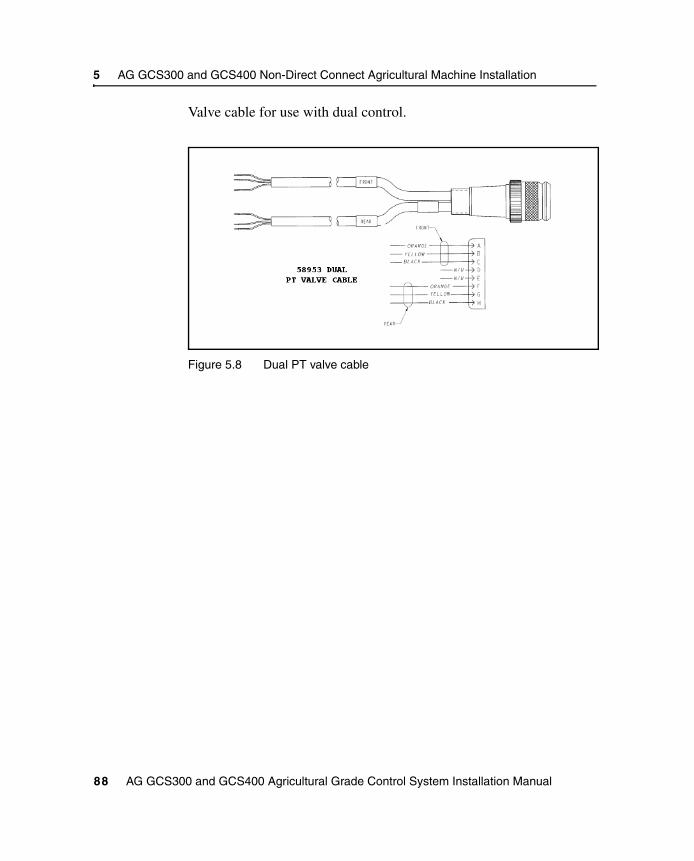
5 AG GCS300 and GCS400 Non-Direct Connect Agricultural Machine Installation
Valve cable for use with dual control.
Figure 5.8 Dual PT valve cable
88 AG GCS300 and GCS400 Agricultural Grade Control System Installation Manual

C H A P T E R
6
Machine Measurement Techniques 6In this chapter:
Introduction
Measurement Techniques

6 Machine Measurement Techniques
6.1 IntroductionThis chapter describes how to measure the machine dimensions for the center pivot scraper and the split axle scraper only. The measurements are required for the Machine Dimensions screens under the Installation / Machine Setup menu.
6.2 Measurement Techniques
Once the system components are installed onto the scraper, a measurement needs to be entered into the CB415 control box. The following section describes the measurement.
6.2.1 Blade width
To measure the blade and enter the value into the CB415, complete the following steps:
90 GCS300, GCS400, GCS500, and GCS600 Installation Manual
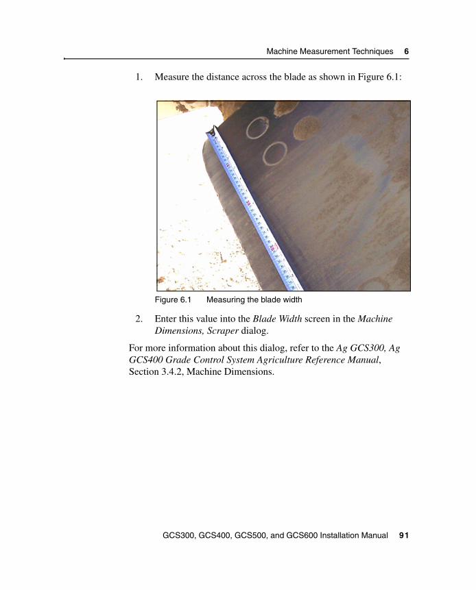
Machine Measurement Techniques 6
1. Measure the distance across the blade as shown in Figure 6.1:
Figure 6.1 Measuring the blade width
2. Enter this value into the Blade Width screen in the Machine Dimensions, Scraper dialog.
For more information about this dialog, refer to the Ag GCS300, Ag GCS400 Grade Control System Agriculture Reference Manual, Section 3.4.2, Machine Dimensions.
GCS300, GCS400, GCS500, and GCS600 Installation Manual 91

6 Machine Measurement Techniques
92 GCS300, GCS400, GCS500, and GCS600 Installation Manual

A P P E N D I X
A
Technical Specifications AIn this appendix:
Introduction
System Interconnections
Component Connectors
Component Electrical and Thermal Specifications

A Technical Specifications
A.1 IntroductionThis appendix provides technical information about the various components, and their interconnections, that make up the system. This appendix describes the following items:
• system interconnections
• component connectors
• component electrical and thermal specifications
Note – Please check the release notes for any updates to these specifications. These specifications are subject to change.
A.2 System InterconnectionsThis section provides cabling information for the cables used in the system:
• Main cable harness
• CB415 display cable
• PM400 power cable
• LR400/LR410 coil connector cable (EM400)
• Trimble remote switch box assembly
• Elevation quick control cable
• EM400 terminated control cable
• EM400 Y-control cable
• SR300 terminated control cable
• SR300 Y-control cable
94 AG GCS300 and GCS400 Agricultural Grade Control System Installation Manual
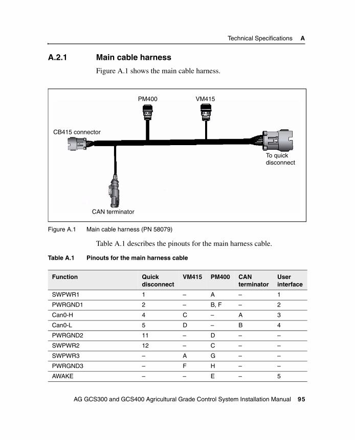
Technical Specifications A
A.2.1 Main cable harness
Figure A.1 shows the main cable harness.
Figure A.1 Main cable harness (PN 58079)
Table A.1 describes the pinouts for the main harness cable.
Table A.1 Pinouts for the main harness cable
Function Quickdisconnect
VM415 PM400 CANterminator
Userinterface
SWPWR1 1 – A – 1
PWRGND1 2 – B, F – 2
Can0-H 4 C – A 3
Can0-L 5 D – B 4
PWRGND2 11 – D – –
SWPWR2 12 – C – –
SWPWR3 – A G – –
PWRGND3 – F H – –
AWAKE – – E – 5
PM400 VM415
To quickdisconnect
CAN terminator
CB415 connector
AG GCS300 and GCS400 Agricultural Grade Control System Installation Manual 95

A Technical Specifications
A.2.2 CB415 display cable
Figure A.2 shows the CB415 display cable.
Figure A.2 CB415 display cable (PN 0395-9560)
Table A.2 describes the pinout information for the CB415 display cable.
Table A.2 CB415 display cable
Function 6-pin Harness 6-socket
SWPWR1 1 A
PWRGND1 2 F
AWAKE 5 E
AWAKE GND 3 C
CAN0 Hi 4 D
Unused 6 B
96 AG GCS300 and GCS400 Agricultural Grade Control System Installation Manual

Technical Specifications A
A.2.3 PM400 power cable
Figure A.3 shows the PM400 power cable.
Figure A.3 PM400 power cable (PN 0395-9130)
Table A.3 describes the PM400 power cable wiring.
Table A.3 PM400 power cable wiring
Function PM400(8-pin, F)
Fuse (ampere) Fly leads
PWR 1 A 10 A Red
PWRGND 1 B – Black
PWR 2 C 10 A White
PWRGND 2 D – Black
Unused E, F – –
PWR 3 G 10 A Green
PWRGND 3 H – Black
AG GCS300 and GCS400 Agricultural Grade Control System Installation Manual 97

A Technical Specifications
A.2.4 LR400/LR410 coil connector cable (EM400)
Figure A.4 shows the LR400 coil connector cable (EM400).
Figure A.4 LR400 coil connector cable (PN 0793-0860)
Figure A.5 shows the LR410 coil connector cable (EM400).
Figure A.5 LR410 coil connector cable (PN 0312-0990)
Table A.4 describes the pinout information for the LR400 coil connector cable.
Table A.4 LR400/LR410 coil connector cable
Function EM4006-pin
LR4006-pin F
SWPWR1 A A
ID B B
CAN0 Hi C C
CAN0 Lo D D
Unused E E
PWRGND1 F F
98 AG GCS300 and GCS400 Agricultural Grade Control System Installation Manual

Technical Specifications A
A.2.5 Trimble remote switch box assembly
Figure A.6 shows the Trimble remote switch box assembly.
Figure A.6 Trimble remote switch box assembly
AG GCS300 and GCS400 Agricultural Grade Control System Installation Manual 99

A Technical Specifications
Table A.5 describes the pinout information for the remote switch box assembly.
A.2.6 Elevation quick control cable
Figure A.7 shows the elevation quick control cable.
Figure A.7 Elevation quick control cable (PN 0395-9150)
Table A.5 Remote switch box assembly
6-pin connector Function
A Left auto / manual
B Right auto / manual
C Offset left
D Offset right
E Setup
F Ground
100 AG GCS300 and GCS400 Agricultural Grade Control System Installation Manual

Technical Specifications A
Table A.6 describes the pinout information for the elevation quick control cable.
A.2.7 EM400 terminated control cable
Figure A.8 shows the EM400 terminated control cable.
Figure A.8 EM400 terminated control cable (PN 57914)
Table A.6 Elevation quick control cable
Function Quick disconnect10-socket
Deutsch12-pin
SWPWR1 A 1
SWPWR2 H 12
PWRGND1 F 2
PWRGND2 G 11
CAN0 Hi C 4
CAN0 Lo D 5
Unused – 3, 10
AG GCS300 and GCS400 Agricultural Grade Control System Installation Manual 101

A Technical Specifications
Table A.7 describes the pinout information for the EM400 terminated control cable.
A.2.8 EM400 Y-control cable
Figure A.9 shows the EM400 Y-control cable.
Figure A.9 EM400 Y-control cable (PN 58321-01)
Table A.7 EM400 terminated control cable
Function 10-socket 10-pin Quick disconnect
SWPWR1 A A
SWPWR2 H H
PWRGND1 F F
PWRGND2 G G
CAN0 Hi C C
CAN0 Lo D D
120 Ohm resistor C D
120 Ohm resistor I J
102 AG GCS300 and GCS400 Agricultural Grade Control System Installation Manual

Technical Specifications A
Table A.8 describes the pinout information for the EM400 Y-control cable.
A.2.9 SR300 terminated control cable
Figure A.11 shows the SR300 terminated control cable.
Figure A.10 SR300 terminated control cable (PN 58362)
Table A.8 EM400 Y-control cable
Function 10-socket 10-pin Quickdisconnect
10-socket Quickdisconnect
SWPWR1 A A A
SWPWR2 H H H
PWRGND1 F F F
PWRGND2 G G G
CAN0 Hi C C C
CAN0 Lo D D D
Unused B, E B, E E
AG GCS300 and GCS400 Agricultural Grade Control System Installation Manual 103

A Technical Specifications
Table A.10 describes the pinout information for the SR300 terminated control cable.
A.2.10 SR300 Y-control cable
Figure A.11 shows the SR300 Y-control cable.
Figure A.11 SR300 Y-control cable (PN 58369-01)
Table A.9 SR300 Y control cable
Function 6-socket 10-pin Quick disconnect
SWPWR1 A A
PWRGND F F
CAN0 Hi C C
CAN0 Lo D D
120 Ohm resistor C D
104 AG GCS300 and GCS400 Agricultural Grade Control System Installation Manual

Technical Specifications A
Table A.10 describes the pinout information for the SR300 Y-control cable.
Table A.10 SR300 Y-control cable
Function 6-socket 10-pin Quick disconnect
10-socket Quick disconnect
SWPWR1 A A A
SWPWR2 – H H
PWRGND1 F F F
PWRGND2 – G G
CAN0 Hi C C C
CAN0 Lo D D D
Unused B, E B, E E
AG GCS300 and GCS400 Agricultural Grade Control System Installation Manual 105

A Technical Specifications
A.3 Component ConnectorsThis section provides the pinout information for each component of the system:
• Elevation sensor connector
• Elevation sensor quick disconnect socket
• PM400 power module
• VM410 valve module
• VM415 valve module
• VM420 valve module
• AS400 angle sensor
• EM400 electric mast connectors
• LR400 and LR410 laser receivers
• SR300 receiver mast
• CB415 connectors
106 AG GCS300 and GCS400 Agricultural Grade Control System Installation Manual

Technical Specifications A
A.3.1 Elevation sensor connector
Figure A.12 shows the elevation sensor connector on the main harness.
Figure A.12 Elevation sensor connector
1 6
712
AG GCS300 and GCS400 Agricultural Grade Control System Installation Manual 107

A Technical Specifications
A.3.2 Elevation sensor quick disconnect socket
Figure A.13 shows the pinout information for the elevation sensor quick disconnect socket.
Figure A.13 Elevation sensor quick disconnect socket pinout
Pin FunctionA SWPWR1B Right/Left function instanceC CAN0 HiD CAN0 LoE UnusedF PWRGND1G PWRGND2H SWPWR2I CAN1 HiJ CAN1 Lo
AH
G
FED
CJ
IB
108 AG GCS300 and GCS400 Agricultural Grade Control System Installation Manual

Technical Specifications A
A.3.3 PM400 power module
Figure A.14 and Figure A.15 show the pinout information for the PM400 power module.
Figure A.14 PM400 power module 8–socket connector pinout
Figure A.15 PM400 power module 8–pin connector pinout
Pin FunctionA SWPWR 1B PWRGND 1 C SWPWR 2D PWRGND 2E AWAKEF AWAKE GNDG SWPWR 3H PWRGND 3
A
B C
D
EF
G H
Pin FunctionA PWR 1B PWRGND 1 C PWR 2D PWRGND 2E UnusedF UnusedG PWR 3H PWRGND 3
A
B C
D
EF
G H
AG GCS300 and GCS400 Agricultural Grade Control System Installation Manual 109

A Technical Specifications
A.3.4 VM410 valve module
Figure A.16 and Figure A.17 show the pinout information for the VM410 valve module.
Figure A.16 VM410 10–pin connector pinout
Figure A.17 VM410 10–socket connector pinout
Pin FunctionA SWPWR 3B UnusedC CAN0 HiD CAN0 LoE UnusedF PWRGND 3G UnusedH UnusedI UnusedJ Unused
A
BC
D
E
FG
HI
J
C
Pin FunctionA Right RaiseB Right LowerC Right GroundD UnusedE UnusedF Left RaiseG Left LowerH Left GroundI UnusedJ Unused
A
BC
D
E
FG
HI
J
C
110 AG GCS300 and GCS400 Agricultural Grade Control System Installation Manual

Technical Specifications A
A.3.5 VM415 valve module
Figure A.20 and Figure A.21 show the pinout information for the VM415 valve module.
Figure A.18 VM415 10–pin connector pinout
Figure A.19 VM415 6–socket connector pinout
Pin FunctionA SWPWR 3B UnusedC CAN0 HiD CAN0 LoE UnusedF PWRGND 3G UnusedH UnusedI UnusedJ Unused
A
BC
D
E
FG
HI
J
C
Pin FunctionA ISOPWRB ISOGNDC CNTL1D CNTL2E Unused F Unused
A
B
C
D
E
F
AG GCS300 and GCS400 Agricultural Grade Control System Installation Manual 111

A Technical Specifications
A.3.6 VM420 valve module
Figure A.20 and Figure A.21 show the pinout information for the VM420 valve module.
Figure A.20 VM420 10–pin connector pinout
Figure A.21 VM420 10–socket connector pinout
Pin FunctionA SWPWR3B Select AC CAN0 HiD CAN0 LoE Select BF PWRGND3G UnusedH UnusedI UnusedJ Unused
A
BC
D
E
FG
HI
J
C
Pin FunctionA Right RaiseB Right LowerC Right GroundD UnusedE UnusedF Left RaiseG Left LowerH Left GroundI UnusedJ Unused
A
BC
D
E
FG
HI
J
C
112 AG GCS300 and GCS400 Agricultural Grade Control System Installation Manual

Technical Specifications A
A.3.7 AS400 angle sensor
Figure A.22 shows the pinout information for the AS400 angle sensor.
Figure A.22 AS400 angle sensor 6–pin connector pinout
Pin FunctionA SWPWR1B Select AC CAN0 HiD CAN0 LoE Select B F PWRGND1
A
B
C
D
E
F
AG GCS300 and GCS400 Agricultural Grade Control System Installation Manual 113

A Technical Specifications
A.3.8 EM400 electric mast connectors
Figure A.23 shows the pinout information for the 10-pin connector on the EM400.
Figure A.23 EM400 10-pin connector pinout
Figure A.24 shows the pinout information for the 6-socket connector on the EM400.
Pin FunctionA SWPWR 3B Right/left function instanceC CAN0 HiD CAN0 LoE UnusedF PWRGND1G PWRGND2H SWPWR2I UnusedJ Unused
H
GF
E
D
CB
AI
J
114 AG GCS300 and GCS400 Agricultural Grade Control System Installation Manual

Technical Specifications A
Figure A.24 EM400 6-socket connector pinout
A.3.9 LR400 and LR410 laser receivers
Figure A.25 shows the pinout information of the LR400 and LR410.
Figure A.25 LR400 and LR410 connector pinout
Pin FunctionA SWPWR1B Right/left function instanceC CAN0 HiD CAN0 LoE Unused F PWRGND1
A
B
C
D
E
F
Pin FunctionA SWPWR1B Right/left function instanceC CAN0 HiD CAN0 LoE Unused F PWRGND1
A
B
C
D
E
F
AG GCS300 and GCS400 Agricultural Grade Control System Installation Manual 115

A Technical Specifications
A.3.10 SR300 receiver mast
Figure A.25 shows the pinout information of the SR300 receiver mast.
Figure A.26 SR300 receiver mast
Pin FunctionA SWPWR1B UnusedC CAN0 HiD CAN0 LoE Unused F PWRGND1
A
B
C
D
E
F
116 AG GCS300 and GCS400 Agricultural Grade Control System Installation Manual
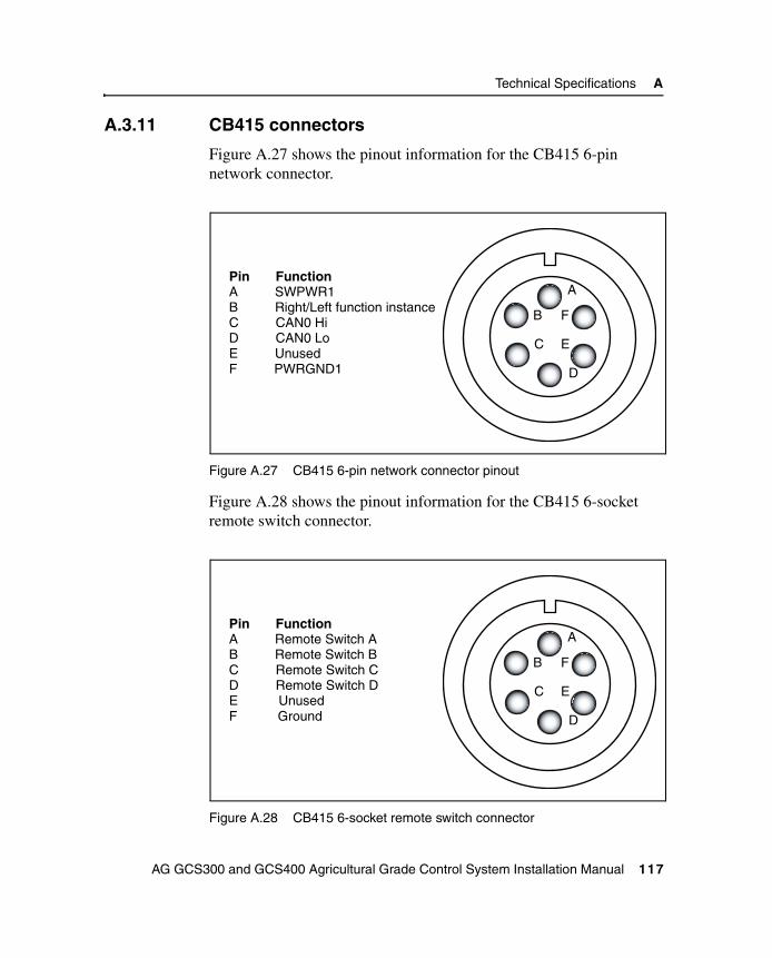
Technical Specifications A
A.3.11 CB415 connectors
Figure A.27 shows the pinout information for the CB415 6-pin network connector.
Figure A.27 CB415 6-pin network connector pinout
Figure A.28 shows the pinout information for the CB415 6-socket remote switch connector.
Figure A.28 CB415 6-socket remote switch connector
Pin FunctionA SWPWR1B Right/Left function instanceC CAN0 HiD CAN0 LoE Unused F PWRGND1
A
B
C
D
E
F
Pin FunctionA Remote Switch AB Remote Switch BC Remote Switch CD Remote Switch DE Unused F Ground
A
B
C
D
E
F
AG GCS300 and GCS400 Agricultural Grade Control System Installation Manual 117

A Technical Specifications
Figure A.29 shows the pinout information for the CB415 RS232 port.
Figure A.29 CB415 RS232 port pinout
12345
6789
Pin Function2 Transmit3 Receive5 Ground
118 AG GCS300 and GCS400 Agricultural Grade Control System Installation Manual

Technical Specifications A
A.4 Component Electrical and Thermal Specifications
This section describes the specifications of the following components:
• PM400 power module
• VM410 valve module
• VM415 valve module
• VM420 valve module
• EM400 electric mast
• SR300 receiver mast
• LR400 laser receiver
• LR410 laser receiver
• AS400 angle sensor
• SA400 single adaptor
• CB415 dual control box
AG GCS300 and GCS400 Agricultural Grade Control System Installation Manual 119

A Technical Specifications
A.4.1 PM400 power module
Table A.11 lists the specifications for the PM400 power module.
A.4.2 VM410 valve module
Table A.12 lists the specifications for the VM410 valve module.
Table A.11 PM400 power module
Characteristic Description
Size 173 mm (height) x 103 mm (width) x 57 mm (depth) (6.75" x 10.3" x 2.2")
Weight 1.4 kg(3 lb)
Operating temperature –29 °C to +60 °C(–20 °F to +140 °F)
Storage temperature –40 °C to +80 °C(–40 °F to +176 °F)
Operating voltage 10 VDC to 30 VDC
Table A.12 VM410 valve module
Characteristic Description
Size 173 mm (height) x 103 mm (width) x 57 mm (depth) (6.75" x 10.3" x 2.2")
Weight 1.4 kg(3 lbs)
Operating temperature –40 °C to +71 °C(–40 °F to +160 °F)
Storage temperature –55 °C to +85 °C(–67 °F to +185 °F)
Operating voltage 9 VDC to 32 VDC
120 AG GCS300 and GCS400 Agricultural Grade Control System Installation Manual
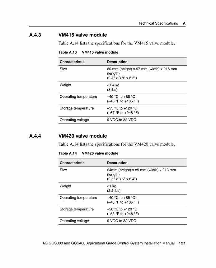
Technical Specifications A
A.4.3 VM415 valve module
Table A.14 lists the specifications for the VM415 valve module.
A.4.4 VM420 valve module
Table A.14 lists the specifications for the VM420 valve module.
Table A.13 VM415 valve module
Characteristic Description
Size 60 mm (height) x 97 mm (width) x 216 mm (length) (2.4" x 3.8" x 8.5")
Weight <1.4 kg(3 lbs)
Operating temperature –40 °C to +85 °C(–40 °F to +185 °F)
Storage temperature –55 °C to +120 °C(–67 °F to +248 °F)
Operating voltage 9 VDC to 32 VDC
Table A.14 VM420 valve module
Characteristic Description
Size 64mm (height) x 89 mm (width) x 213 mm (length) (2.5" x 3.5" x 8.4")
Weight <1 kg(2.2 lbs)
Operating temperature –40 °C to +85 °C(–40 °F to +185 °F)
Storage temperature –50 °C to +120 °C(–58 °F to +248 °F)
Operating voltage 9 VDC to 32 VDC
AG GCS300 and GCS400 Agricultural Grade Control System Installation Manual 121

A Technical Specifications
A.4.5 EM400 electric mast
Table A.15 lists the specifications for the EM400 electric mast.
A.4.6 SR300 receiver mast
Table A.17 lists the specifications for the SR300 receiver mast.
Table A.15 EM400 electric mast
Characteristic Description
Size Height retracted 1640 mm (64.6”)Height extended 2900 mm (114.2”)Diameter at base 240 mm (9.4”)
Weight Approximately 25 kg(55 lbs)
Operating temperature –29 °C to +60 °C(–20 °F to +140 °F)
Storage temperature –40 °C to +80 °C(–40 °F to + 176 °F)
Operating voltage 10 VDC to 30 VDC
Adjustment range 1640 mm (64.5”) to 2900 mm (113”)
Operating speed 300 mm (11.8”) per sec
Table A.16 SR300 receiver mast
Characteristic Description
Size 128.3 cm (height) x 20.3 cm (width) x 22.9 cm (depth)(50.5" x 8" x 9”)
Weight 19 kg(42 lbs)
Input voltage Machine power 10 VDC to 30 VDC
Operating temperature –29 °C to +60 °C(–20 °F to +140 °F)
122 AG GCS300 and GCS400 Agricultural Grade Control System Installation Manual

Technical Specifications A
A.4.7 LR400 laser receiver
Table A.17 lists the specifications for the LR400 laser receiver.
Storage temperature –40 °C to +80 °C(–40 °F to + 176 °F)
Network capable CAN (Controller Area Network)
Laser detection angle 360°
Laser detection range 460 m (1500 ft)
Table A.17 LR400 laser receiver
Characteristic Description
Size 305 mm (height) x 152 mm (width) x 60 mm (depth) or 270 mm (depth with SA400)(12" x 6" x 2.4" or 10.6”)
Weight 1.6 kg or 2.85 kg with SA400(3.5 lbs or 6.3 lbs)
Operating temperature –29 °C to +60 °C(–20 °F to +140 °F)
Storage temperature –40 °C to +80 °C(–40 °F to + 176 °F)
Operating voltage 9 VDC to 30 VDC
Table A.16 SR300 receiver mast
Characteristic Description
AG GCS300 and GCS400 Agricultural Grade Control System Installation Manual 123
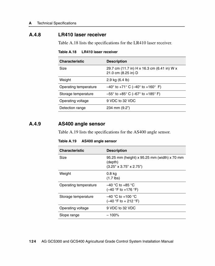
A Technical Specifications
A.4.8 LR410 laser receiver
Table A.18 lists the specifications for the LR410 laser receiver.
A.4.9 AS400 angle sensor
Table A.19 lists the specifications for the AS400 angle sensor.
Table A.18 LR410 laser receiver
Characteristic Description
Size 29.7 cm (11.7 in) H x 16.3 cm (6.41 in) W x 21.0 cm (8.25 in) D
Weight 2.9 kg (6.4 lb)
Operating temperature –40° to +71° C (–40° to +160° F)
Storage temperature –55° to +85° C (–67° to +185° F)
Operating voltage 9 VDC to 32 VDC
Detection range 234 mm (9.2”)
Table A.19 AS400 angle sensor
Characteristic Description
Size 95.25 mm (height) x 95.25 mm (width) x 70 mm (depth) (3.25" x 3.75" x 2.75")
Weight 0.8 kg(1.7 lbs)
Operating temperature –40 °C to +85 °C(–40 °F to +176 °F)
Storage temperature –40 °C to +100 °C(–40 °F to + 212 °F)
Operating voltage 9 VDC to 32 VDC
Slope range – 100%
124 AG GCS300 and GCS400 Agricultural Grade Control System Installation Manual

Technical Specifications A
A.4.10 SA400 single adaptor
Table A.20 lists the specifications for the SA400 single adaptor.
A.4.11 CB415 dual control box
Table A.21 lists the specifications for the CB415 dual control box.
Table A.20 SA400 single adaptor
Characteristic Description
Size
Weight
Operating temperature
Storage temperature –40 °C to +80 °C(–40 °F to + 176 °F)
Operating voltage 9 VDC to 32 VDC
Table A.21 CB415 dual control box
Characteristic Description
Size 203 mm (height) x 127 mm (width) x 102 mm (depth) (8" x 5" x 4")
Weight <1.4 kg(3 lbs)
Operating temperature –29 °C to +60 °C(–20 °F to +140 °F)
Storage temperature –40 °C to +80 °C(–40 °F to + 176 °F)
Operating voltage 9 VDC to 30 VDC
AG GCS300 and GCS400 Agricultural Grade Control System Installation Manual 125

A Technical Specifications
126 AG GCS300 and GCS400 Agricultural Grade Control System Installation Manual

A P P E N D I X
B
System Maintenance BIn this appendix:
Introduction
General Maintenance Procedures

B System Maintenance
B.1 IntroductionThis chapter describes basic maintenance steps that can be followed to ensure system accuracy is maintained. These include but are not restricted to system inspections, calibration procedures, and machine maintenance.
B.2 General Maintenance ProceduresThe common maintenance procedures for the Grade Control System are as follows:
• Routine calibration of the laser transmitter is required to maintain accuracy. Transmitter calibration is a simple process and instructions are included with the unit.
• Daily inspection of the cables is required to make sure they are not cut or pulled during operation. Repair or replace the cables as required.
• Periodic inspection of the drain holes for clogging is required. Both the CB415 and EM400 have built-in drain holes located on the side or bottom of the unit.
• Auto Valve Calibration. Valve calibration is required when the Ag GCS300 and GCS400 is installed and also when:
– A VM410, VM415, or VM420 valve module is replaced.
– Hydraulic performance is degraded or hydraulic components are changed.
– The equipment is exposed to extreme temperature change. Once the valves have been calibrated, then speed control of the implement can be readjusted using the Valve Speed menu item in the Configuration menu.
• Ensure implement hydraulics and components are inspected for wear or damage. Leaking hydraulic cylinders or connections may affect system performance.
128 AG GCS300 and GCS400 Agricultural Grade Control System

Index
AAS400 angle sensorpinouts 113technical specifications 124
auxiliary auto mode switchCase MX Series 47Case STX Series 61
B
blade lengthbulldozer 90
bulldozerblade length 90measurement techniques 90
C
calibrationCase MX Series 44Challenger MT Series 75John Deere 27, 32
Case MX Series 35–49auxiliary auto mode switch 47calibration 44display box 35fault / error codes 46mast mounting 42power module 36
quick disconnect bracket 42system calibration procedure 48system configuration 43system harness 35valve connection 40VM415 valve module 38
Case STX Series 49–62auxiliary auto mode switch 61display box 49fault / error codes 60mast mounting 55power connection 56power module 51quick disconnect bracket 54system calibration procedure 62system configuration 57system harness 49tractor configuration 58valve connection 56VM415 valve module 52
CB415 display boxCase MX Series 35Case STX Series 49Challenger MT Series 68connector cable 96connector, pinouts 117John Deere 18technical specifications 125
Challenger MT Series 62–76display box 68machine validation 63
AG GCS300 and GCS400 Agricultural Grade Control System Installation Manual 129

Index
mast mounting 74power module 68quick disconnect assembly 74system calibration procedure 75system harness 67
component connectors 106–118component specifications 119
D
Danfoss valve hydraulics 82direct cable connection 74
Case MX Series 40Case STX Series 56Challenger MT Series 71John Deere 24
E
elevation sensorconnector, pinouts 107quick disconnect socket, pinouts 108
EM400 electric mastconnector, pinouts 114technical specifications 122
environmental factors 13
F
feedback 3
I
installationcables, planning of 11environmental factors 13operational considerations 12pre-installation check 6
tools 11visiting site for check 6
J
John Deere 18–34calibration 27clear faults 33display box 18mast mounting 25power module 20quick disconnect bracket 25system configuration 26system harness 18valve connection 24VM415 valve module 21
L
LR400 laser receiverpinouts 115, 116technical specifications 123
LR400/LR410 coil connector cable pinoutsEM400 98
LR410 laser receiverpinouts 115, 116technical specifications 124
M
machine validation, Challenger MT Series 63
maintenance 128mast mounting
Case MX Series 42Case STX Series 55Challenger MT Series 74John Deere 25
130 AG GCS300 and GCS400 Agricultural Grade Control System Installation Manual

Index
measurement techniquesbulldozer 90
O
operational considerations, overview 12
P
pinoutsAS400 113CB415 connector 117CB415, connector cable 96elevation sensor connector 107elevation sensor quick disconnect
socket 108EM400 114LR400 115, 116LR400/LR410 coil connector cable
EM400 98LR410 115, 116PM400 109PM400 power cable 97remote switches 99VM410 110VM415 111VM420 112
PM400Case MX Series 36Case STX Series 51Challenger MT Series 68John Deere 20pinouts 109power cable pinouts 97technical specifications 120
power connection, Case STX Series 56pre-installation
check 6requirements 9–11
Q
quick disconnect bracketCase MX Series 42Case STX Series 54Challenger MT Series 74John Deere 25
R
remote switchespinouts 99
Roll Over Protective Structure (ROPS) 12
S
SA400 single adaptor, technical specifications 125
shipment damage claims 2specifications, electrical and thermal 119–
125system calibration procedure
Case MX Series 48Case STX Series 62Challenger MT Series 75
system configurationCase MX Series 43Case STX Series 57John Deere 26
system harnessCase MX Series 35Case STX 49Challenger MT Series 67John Deere 18
system interconnections 94–104system introduction 2system maintenance 128
AG GCS300 and GCS400 Agricultural Grade Control System Installation Manual 131

Index
T
technical assistance 2technical specifications
AS400 124CB415 125EM400 122LR400 123LR410 124PM400 120SA400 125VM410 120VM415 121VM420 121
V
valve connectionCase MX Series 40Case STX Series 56Challenger MT Series 71John Deere 24
valve module mountingCase MX Series 38Case STX Series 52John Deere 21
VM410 valve modulepinouts 110technical specifications 120
VM415 valve modulepinouts 111technical specifications 121
VM420 valve modulepinouts 112technical specifications 121
132 AG GCS300 and GCS400 Agricultural Grade Control System Installation Manual