agco rmc operator manual - norac · pdf fileagco rmc operator manual version 4 ... before...
TRANSCRIPT

AGCO RMC Operator Manual
Version 4 Software

Printed in Canada Copyright 2012 by NORAC Systems International Inc. Reorder P/N: UC5-BC-MANUAL-AGCO-RMC Operator Manual Rev C
NOTICE: NORAC Systems International Inc. reserves the right to improve products and their specifications without notice and without the requirement to update products sold previously. Every effort has been made to ensure the accuracy of the information contained in this manual. The technical information in this manual was reviewed at the time of approval for publication.
Contents
1 SAFETY PRECAUTIONS ........................................................................................... 1
2 TECHNICAL SPECIFICATIONS ............................................................................... 2
3 SYSTEM DESCRIPTION ............................................................................................ 3
3.1 General UC5 System Layout ....................................................................................................................................................3
3.2 Height Sensors ............................................................................................................................................................................5
3.3 Roll Sensors .................................................................................................................................................................................5
3.4 Linear Damper ............................................................................................................................................................................6
3.5 Modules .........................................................................................................................................................................................6
4 ICON DESCRIPTIONS ............................................................................................... 8
5 OPERATION .............................................................................................................. 10
5.1 Main Run Screen ...................................................................................................................................................................... 10
5.2 Setting Control Options ........................................................................................................................................................ 11
5.3 Sprayer Manual Boom Height Switches .............................................................................................................................. 13
5.4 Error Indicators ........................................................................................................................................................................ 14
6 UNDERSTANDING THE UC5™ SYSTEM ............................................................ 15
6.1 Boom Reaction Time .............................................................................................................................................................. 15
6.2 Ditches, Waterways and Outside Rounds ......................................................................................................................... 15
6.3 Driving Through Ditches and Over Terraces ................................................................................................................... 15
6.4 Soil Mode and Crop Mode .................................................................................................................................................... 15
6.5 Sensing Further Ahead of the Boom ................................................................................................................................... 15
6.6 Height Sensor Limitations ...................................................................................................................................................... 16
7 SETUP ......................................................................................................................... 17
7.1 Navigating to the UC5™ Setup Menu ................................................................................................................................ 17
7.2 Hydraulic Retune ..................................................................................................................................................................... 18
7.3 Boom Geometry Test............................................................................................................................................................. 20
7.4 Manual Setup ............................................................................................................................................................................. 21
8 DIAGNOSTICS MENU ............................................................................................. 27
9 MAINTENANCE ........................................................................................................ 29
10 UC5 MENU STRUCTURE ........................................................................................ 30
1
1 Safety Precautions
The UC5 Spray Height Control system will greatly improve your spraying height accuracy and protect the boom against damage in a wide variety of field conditions. However, under some circumstances performance may be limited. The operator of the sprayer must remain alert at all times and override the automatic control when necessary.
Important
Under no circumstances should any service work be performed on the machinery while the UC5 Spray Height Control system is in the Automatic Mode.
Always ensure that the UC5 Spray Height Control system is powered down or in Manual Mode:
Before leaving the operator’s seat.
While the machine is not moving.
When transporting the machine.
Before working on any part of the booms:
Set the UC5 system to Manual Mode.
Turn the sprayer engine off.
Do not operate this system before:
Reading and understanding the operator’s manual.
Thoroughly understanding the machine operation.
NORAC firmware updates are available using the AGCO EDT tool. Please contact your dealer for more information.

2
2 Technical Specifications
CAN ICES-3(A)/NMB-3(A) This device complies with part 15 of the FCC Rules. Operation is subject to the following two conditions: (1) This device may not cause harmful interference, and (2) this device must accept any interference received, including interference that may cause undesired operation.
This equipment has been tested and found to comply with the limits for a Class A digital device, pursuant to part 15 of the FCC Rules. These limits are designed to provide reasonable protection against harmful interference when the equipment is operated in a commercial environment. This equipment generates, uses, and can radiate radio frequency energy and, if not installed and used in accordance with the instruction manual, may cause harmful interference to radio communications. Operation of this equipment in a residential area is likely to cause harmful interference in which case the user will be required to correct the interference at their own expense.
This Class A digital apparatus complies with Canadian ICES-003.
Pursuant to EMC Directive – Article 9, this product is not intended for residential use.
Table 1: System Specifications
Supply Voltage (rated) 12VDC Supply Current (rated) 5A Hydraulic Pressure (maximum) 3300 psi Baud Rate 250 kbps Clock Frequency (maximum) 96 MHz Solenoid Valve PWM Frequency 300 Hz Ultrasonic Sensor Transmit Frequency 50 kHz Operating Temperature Range 0°C to 80°C
3
3 System Description
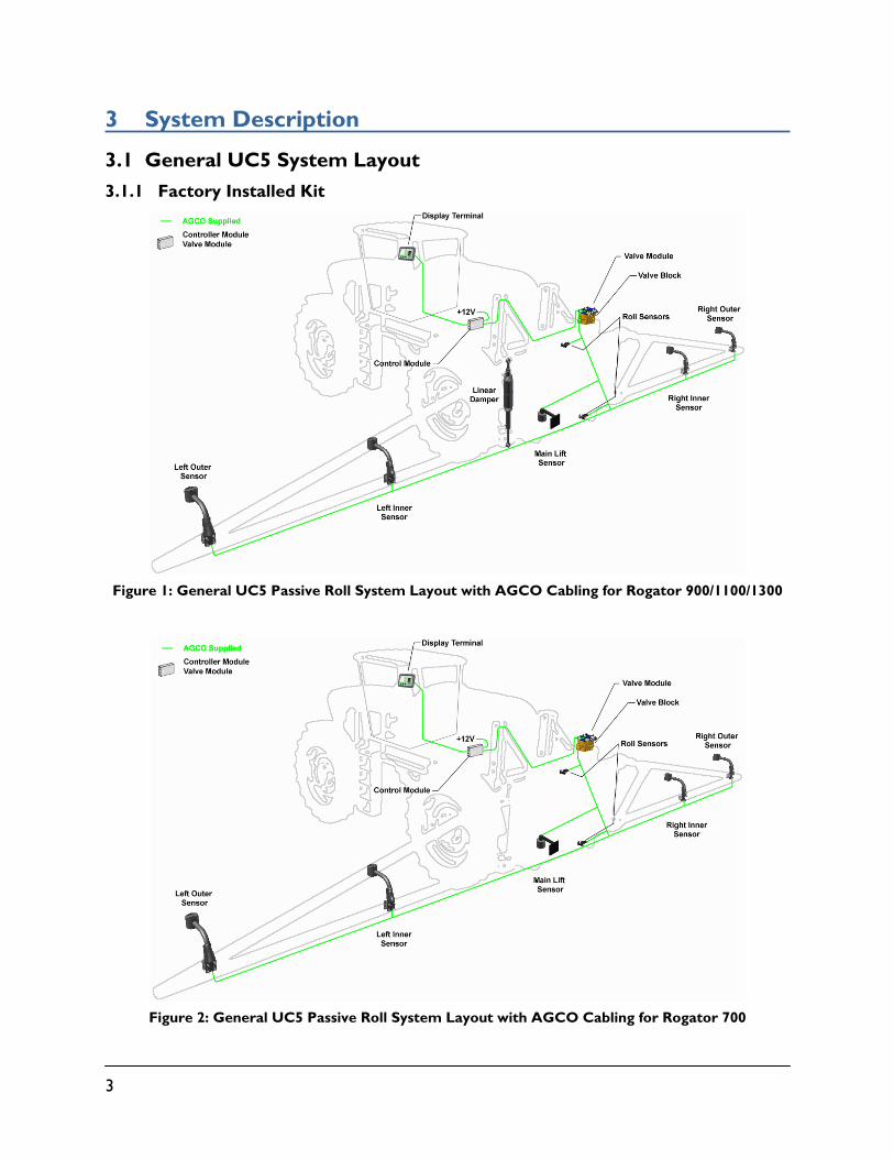
3.1 General UC5 System Layout
3.1.1 Factory Installed Kit
Figure 1: General UC5 Passive Roll System Layout with AGCO Cabling for Rogator 900/1100/1300
Figure 2: General UC5 Passive Roll System Layout with AGCO Cabling for Rogator 700
4
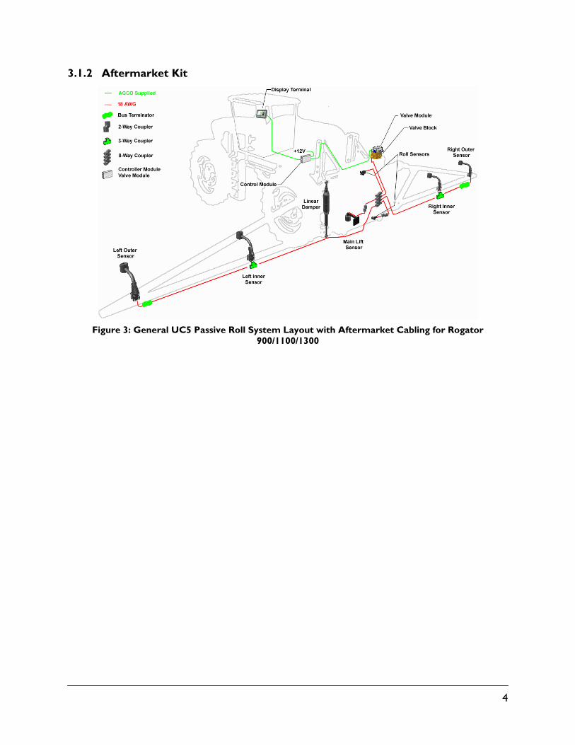
3.1.2 Aftermarket Kit
Figure 3: General UC5 Passive Roll System Layout with Aftermarket Cabling for Rogator
900/1100/1300
5
3.2 Height Sensors
Height sensors use an ultrasonic signal to measure distance to the ground or crop canopy.
Normally there is three or five height sensors used. A sensor is mounted to the outer part of each boom tip, and another sensor is mounted to the center section. Two optional sensors may be mounted near the middle of each boom.
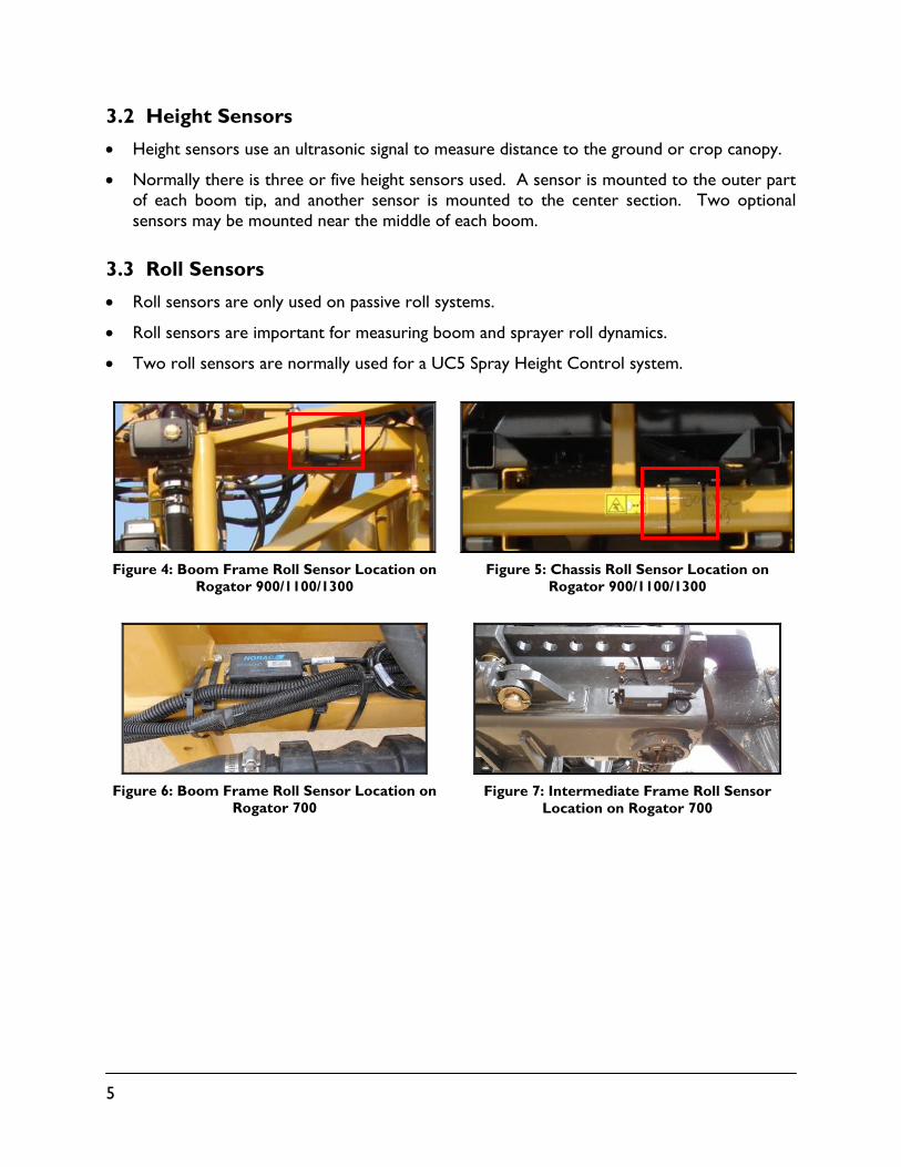
3.3 Roll Sensors
Roll sensors are only used on passive roll systems.
Roll sensors are important for measuring boom and sprayer roll dynamics.
Two roll sensors are normally used for a UC5 Spray Height Control system.
Figure 4: Boom Frame Roll Sensor Location on
Rogator 900/1100/1300
Figure 5: Chassis Roll Sensor Location on
Rogator 900/1100/1300
Figure 6: Boom Frame Roll Sensor Location on
Rogator 700
Figure 7: Intermediate Frame Roll Sensor
Location on Rogator 700
6
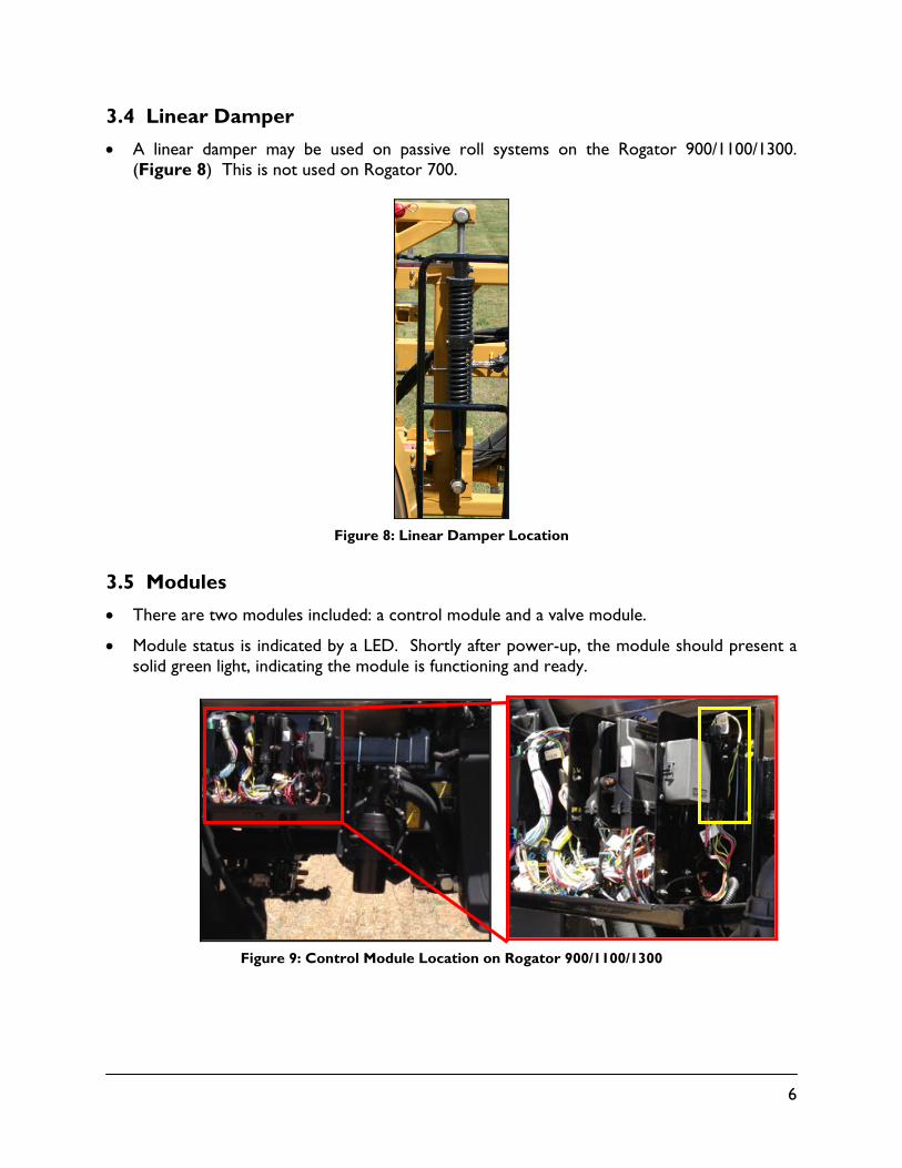
3.4 Linear Damper
A linear damper may be used on passive roll systems on the Rogator 900/1100/1300. (Figure 8) This is not used on Rogator 700.
Figure 8: Linear Damper Location
3.5 Modules
There are two modules included: a control module and a valve module.
Module status is indicated by a LED. Shortly after power-up, the module should present a solid green light, indicating the module is functioning and ready.
Figure 9: Control Module Location on Rogator 900/1100/1300

7
Figure 10: Control Module Location on Rogator 700
Figure 11: Valve Module Location on Rogator 900/1100/1300
Figure 12: Valve Module Location on Rogator 700

8
4 Icon Descriptions
The following table illustrates and describes the icons used in the display. These icons may look different depending on the type of display you have.
Table 2: Display Icons
Icon Name Description
Check Confirms selection or completion of a step
Error Indicates when there is an error
Next Navigates to the next page
Previous Navigates to the previous page
Home
This button always returns directly to the Run Screen
Manual Mode (Active)
Indicates the system is in Manual Mode
Manual Mode (Inactive)
Changes to Manual Mode when the system is in Automatic Mode
Automatic Mode (Active)
Indicates the system is in Automatic Mode
Automatic Mode (Inactive)
Changes to Automatic Mode when the system is in Manual Mode
Settings Navigates to the Settings screen
Cancel Cancels current selection or operation
Setup Navigates to the Automatic/Manual setup screen

9
Options Navigates to the Options screen
Diagnostics Navigates to the Diagnostics screen
Advanced Settings Navigates to the Advanced settings
Automatic Setup Starts an Automatic setup
Retune Starts a Retune
Boom Geometry Test
Starts a boom geometry (push) test
Sensor Setup/ Diagnostics
Navigates to the Manual sensor setup or Sensor diagnostics screens
Valve Setup/ Diagnostics
Navigates to the Manual valve setup or Hydraulic diagnostics screens
Switches Navigates to the Manual remote switches screen
Versions Navigates to the UC5™ modules versions screen
Geometry Navigates to the boom geometry screen
Manual Valve Drive Navigates to the Manual valve drive screen
10
5 Operation
5.1 Main Run Screen
The majority of functional settings and controls can be accessed on the NORAC UC5 main run screen. An image of the boom, with the height of each boom section is displayed. To navigate to the UC5 screens, press the UC5 icon on RMC.
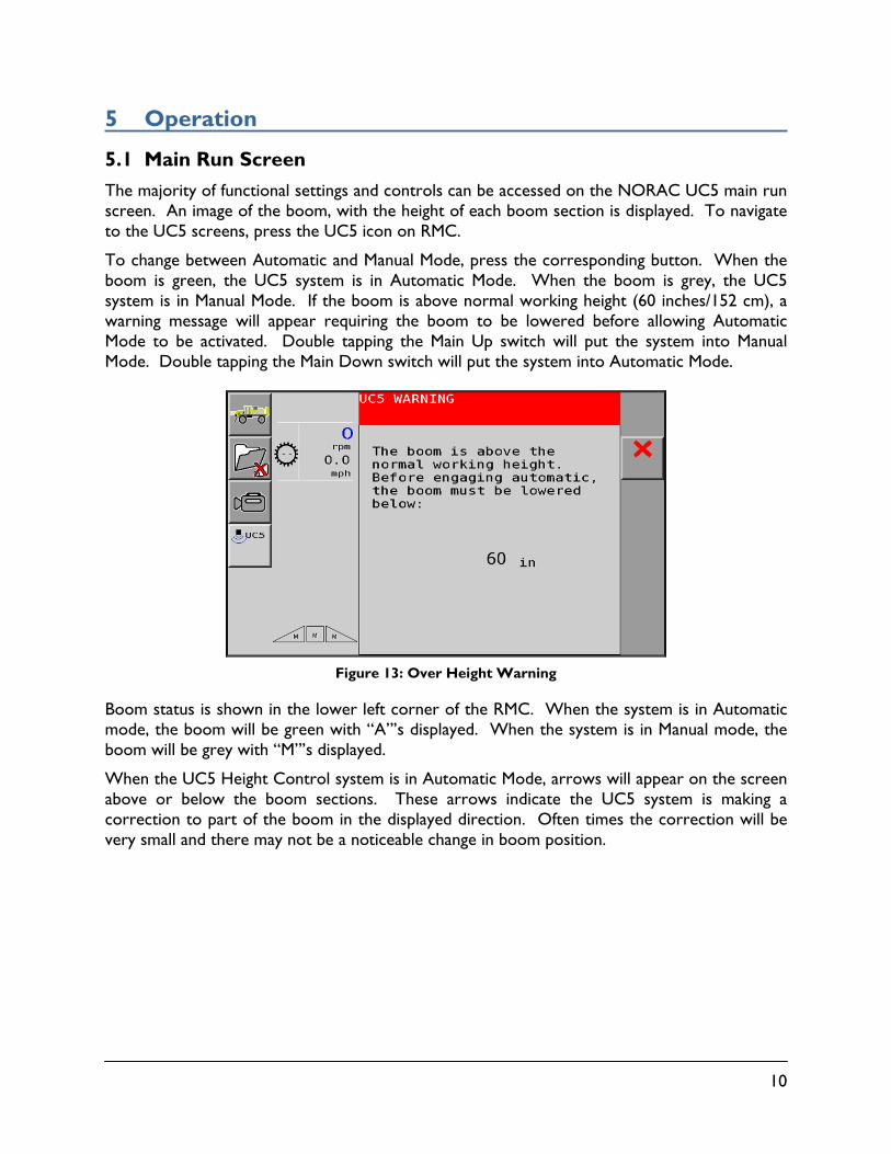
To change between Automatic and Manual Mode, press the corresponding button. When the boom is green, the UC5 system is in Automatic Mode. When the boom is grey, the UC5 system is in Manual Mode. If the boom is above normal working height (60 inches/152 cm), a warning message will appear requiring the boom to be lowered before allowing Automatic Mode to be activated. Double tapping the Main Up switch will put the system into Manual Mode. Double tapping the Main Down switch will put the system into Automatic Mode.
Figure 13: Over Height Warning
Boom status is shown in the lower left corner of the RMC. When the system is in Automatic mode, the boom will be green with “A”’s displayed. When the system is in Manual mode, the boom will be grey with “M”’s displayed.
When the UC5 Height Control system is in Automatic Mode, arrows will appear on the screen above or below the boom sections. These arrows indicate the UC5 system is making a correction to part of the boom in the displayed direction. Often times the correction will be very small and there may not be a noticeable change in boom position.
11
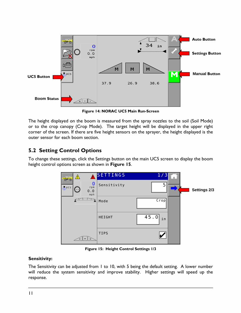
Figure 14: NORAC UC5 Main Run-Screen
The height displayed on the boom is measured from the spray nozzles to the soil (Soil Mode) or to the crop canopy (Crop Mode). The target height will be displayed in the upper right corner of the screen. If there are five height sensors on the sprayer, the height displayed is the outer sensor for each boom section.
5.2 Setting Control Options
To change these settings, click the Settings button on the main UC5 screen to display the boom height control options screen as shown in Figure 15.
Figure 15: Height Control Settings 1/3
Sensitivity:
The Sensitivity can be adjusted from 1 to 10, with 5 being the default setting. A lower number will reduce the system sensitivity and improve stability. Higher settings will speed up the response.
Settings Button
Manual Button
Settings 2/3
UC5 Button
Boom Status
Auto Button
12
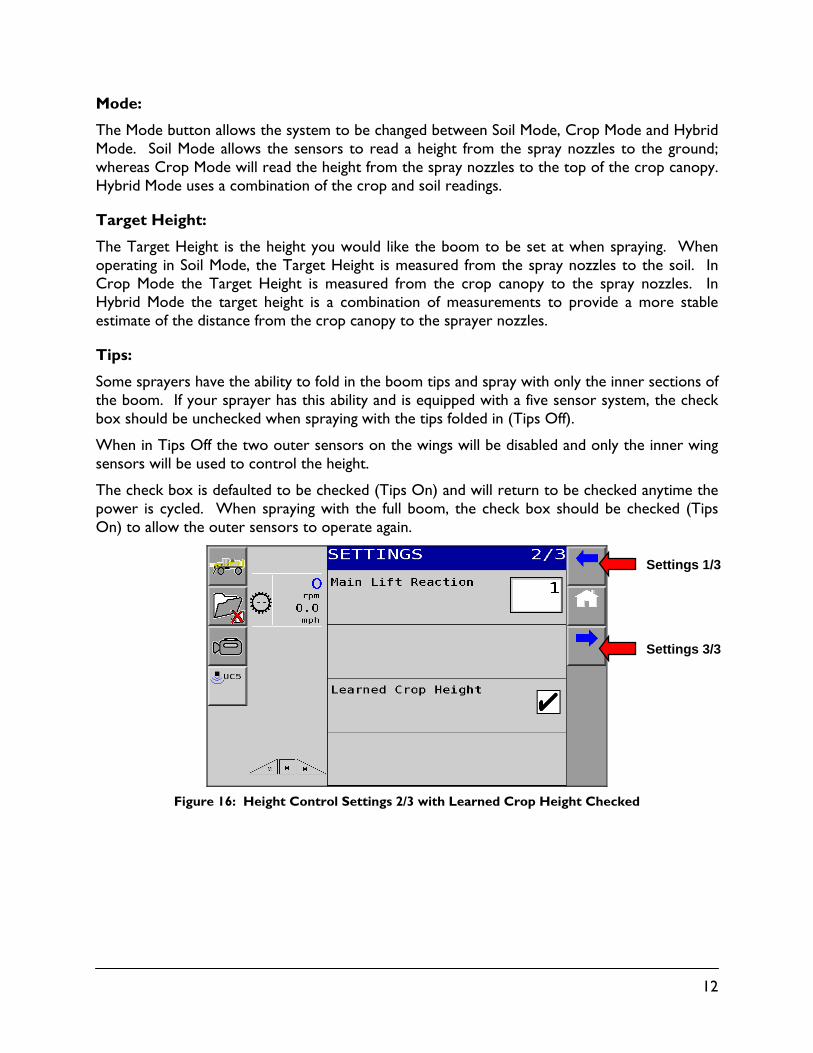
Mode:
The Mode button allows the system to be changed between Soil Mode, Crop Mode and Hybrid Mode. Soil Mode allows the sensors to read a height from the spray nozzles to the ground; whereas Crop Mode will read the height from the spray nozzles to the top of the crop canopy. Hybrid Mode uses a combination of the crop and soil readings.
Target Height:
The Target Height is the height you would like the boom to be set at when spraying. When operating in Soil Mode, the Target Height is measured from the spray nozzles to the soil. In Crop Mode the Target Height is measured from the crop canopy to the spray nozzles. In Hybrid Mode the target height is a combination of measurements to provide a more stable estimate of the distance from the crop canopy to the sprayer nozzles.
Tips:
Some sprayers have the ability to fold in the boom tips and spray with only the inner sections of the boom. If your sprayer has this ability and is equipped with a five sensor system, the check box should be unchecked when spraying with the tips folded in (Tips Off).
When in Tips Off the two outer sensors on the wings will be disabled and only the inner wing sensors will be used to control the height.
The check box is defaulted to be checked (Tips On) and will return to be checked anytime the power is cycled. When spraying with the full boom, the check box should be checked (Tips On) to allow the outer sensors to operate again.
Figure 16: Height Control Settings 2/3 with Learned Crop Height Checked
Settings 1/3
Settings 3/3
13
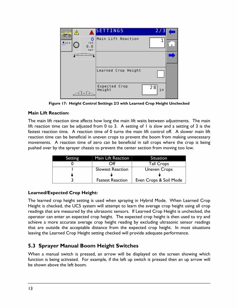
Figure 17: Height Control Settings 2/3 with Learned Crop Height Unchecked
Main Lift Reaction:
The main lift reaction time affects how long the main lift waits between adjustments. The main lift reaction time can be adjusted from 0 to 3. A setting of 1 is slow and a setting of 3 is the fastest reaction time. A reaction time of 0 turns the main lift control off. A slower main lift reaction time can be beneficial in uneven crops to prevent the boom from making unnecessary movements. A reaction time of zero can be beneficial in tall crops where the crop is being pushed over by the sprayer chassis to prevent the center section from moving too low.
Setting Main Lift Reaction Situation 0 Off Tall Crops 1 Slowest Reaction Uneven Crops 3 Fastest Reaction Even Crops & Soil Mode
Learned/Expected Crop Height:
The learned crop height setting is used when spraying in Hybrid Mode. When Learned Crop Height is checked, the UC5 system will attempt to learn the average crop height using all crop readings that are measured by the ultrasonic sensors. If Learned Crop Height is unchecked, the operator can enter an expected crop height. The expected crop height is then used to try and achieve a more accurate average crop height reading by excluding ultrasonic sensor readings that are outside the acceptable distance from the expected crop height. In most situations leaving the Learned Crop Height setting checked will provide adequate performance.
5.3 Sprayer Manual Boom Height Switches
When a manual switch is pressed, an arrow will be displayed on the screen showing which function is being activated. For example, if the left up switch is pressed then an up arrow will be shown above the left boom.

14
Tilt (Variable Geometry) Switches:
While in Automatic Mode if either left or right tilt switches are pressed, the corresponding boom section will go into Manual Mode. To return all boom sections to Automatic Mode, press the Auto button.
Main Lift Switch:
Pressing and holding the main lift switch will always put the system into Manual Mode.
Double tapping the Main Up switch will put the system into Manual Mode.
Double tapping the Main Down switch will put the system into Automatic Mode.
5.4 Error Indicators
If an error is detected in the system, the Error button will appear on the screen as shown in Figure 18. The boom with the error will go to its Manual state with the ‘M’ or ‘A’ on the display flashing depending on whether the system is in Auto or Manual mode.
Selecting the Error button allows all active system errors to be viewed (Figure 19). To navigate between multiple errors, use the Next and Previous arrow buttons.
Figure 18: Error Indicator
Figure 19: Sample Error Viewing Screen

15
6 Understanding the UC5™ System
The UC5™ Spray Height Control system will work well in most situations. As with any equipment, it is important that the operator remains alert at all times. There may be some situations and terrain where performance is limited and in these situations the operator must resume manual control of the booms. A discussion of settings and performance is given below to clarify these situations.
6.1 Boom Reaction Time
Sprayer hydraulics and boom suspension systems are the governing components to boom reaction time. The maximum hydraulic speed of the boom is determined by the sprayer and is not diminished by the addition of the UC5™ hydraulic system.
6.2 Ditches, Waterways and Outside Rounds
In many situations it is necessary to spray with one sensor reading over terrain that does not reflect the same situation of the rest of the boom. These situations may arise when spraying over ditches, waterways, or field edges. When spraying in these situations the operator must remain alert and override the height controller when necessary.
6.3 Driving Through Ditches and Over Terraces
Changes in terrain such as driving over terraces or through ditches are special performance situations. This type of terrain can cause the sprayer to pitch and roll significantly and when operating at high speeds this can cause rapid changes in boom tip height. Sprayer hydraulic systems are not capable of tip speeds high enough to correct for the boom tip error. The operator must recognize these situations before they occur and manually raise the boom to a safe height.
6.4 Soil Mode, Crop Mode and Hybrid Mode
Height sensors use “smart sensor” technology, which take measurements from both the top of crop canopy and from the soil surface. This allows the user to select Hybrid, Crop or Soil Mode. In Soil Mode the target height is measured from the soil to the sprayer nozzle. In Crop Mode the target height is measured from the crop canopy to the sprayer nozzle. Hybrid Mode uses a combination of the crop and soil readings to improve control.
6.5 Sensing Further Ahead of the Boom
A common misconception is moving the sensor further ahead of the boom will increase performance. Moving the sensor further ahead of the boom increases the distance between the nozzle and sensor. This puts the sensor at a different location within the field than the nozzles, which introduces a height error at the nozzles. In severe terrain this height error can bring the nozzles close to the ground as the sensor reads over the crest of the hill or down a ditch.
16
6.6 Height Sensor Limitations
The UC5™ sensors are designed and built specifically for agricultural purposes. However, the ultrasonic transducer must be clean and dry for optimal performance. The foam disc fitted into the bottom of the sensor protects the transducer from dust. If the protective foams become wet from rain or drift from the spray nozzles the sensors may have trouble reading. Furthermore, if the transducer itself becomes wet, leave the UC5™ system on, but in Manual Mode. The transducer’s vibrations will clean itself of the water and after a few minutes it will begin to function again.
The height sensors will provide height readings from 22 to 300cm (9 to 120 inches), under typical conditions.

17
7 Setup
When the sprayer leaves the factory the UC5 system is calibrated and should be performing correctly. The information in the following sections can be used for further calibration and diagnostics. This is intended for expert users.
7.1 Navigating to the UC5™ Setup Menu
To perform either the Automatic or Manual System Setup, the user must navigate to the Setup screen. The system must be in Manual Mode to perform setups.
When the system is in Manual Mode, select the Settings button.
Select the Next button.
Select the Setup button.
18
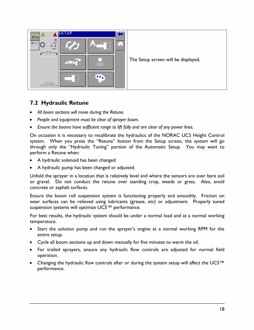
The Setup screen will be displayed.
7.2 Hydraulic Retune
All boom sections will move during the Retune.
People and equipment must be clear of sprayer boom.
Ensure the booms have sufficient range to lift fully and are clear of any power lines.
On occasion it is necessary to recalibrate the hydraulics of the NORAC UC5 Height Control system. When you press the “Retune” button from the Setup screen, the system will go through only the “Hydraulic Tuning” portion of the Automatic Setup. You may want to perform a Retune when:
A hydraulic solenoid has been changed.
A hydraulic pump has been changed or adjusted.
Unfold the sprayer in a location that is relatively level and where the sensors are over bare soil or gravel. Do not conduct the retune over standing crop, weeds or grass. Also, avoid concrete or asphalt surfaces.
Ensure the boom roll suspension system is functioning properly and smoothly. Friction on wear surfaces can be relieved using lubricants (grease, etc) or adjustment. Properly tuned suspension systems will optimize UC5™ performance.
For best results, the hydraulic system should be under a normal load and at a normal working temperature.
Start the solution pump and run the sprayer’s engine at a normal working RPM for the entire setup.
Cycle all boom sections up and down manually for five minutes to warm the oil.
For trailed sprayers, ensure any hydraulic flow controls are adjusted for normal field operation.
Changing the hydraulic flow controls after or during the system setup will affect the UC5™ performance.
19
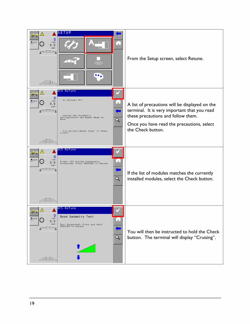
From the Setup screen, select Retune.
A list of precautions will be displayed on the terminal. It is very important that you read these precautions and follow them.
Once you have read the precautions, select the Check button.
If the list of modules matches the currently installed modules, select the Check button.
You will then be instructed to hold the Check button. The terminal will display “Cruising”.
20
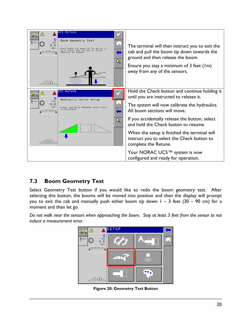
The terminal will then instruct you to exit the cab and pull the boom tip down towards the ground and then release the boom.
Ensure you stay a minimum of 3 feet (1m) away from any of the sensors.
Hold the Check button and continue holding it until you are instructed to release it.
The system will now calibrate the hydraulics. All boom sections will move.
If you accidentally release the button, select and hold the Check button to resume.
When the setup is finished the terminal will instruct you to select the Check button to complete the Retune.
Your NORAC UC5™ system is now configured and ready for operation.
7.3 Boom Geometry Test
Select Geometry Test button if you would like to redo the boom geometry test. After selecting this button, the booms will be moved into position and then the display will prompt you to exit the cab and manually push either boom tip down 1 – 3 feet (30 – 90 cm) for a moment and then let go.
Do not walk near the sensors when approaching the boom. Stay at least 3 feet from the sensor to not induce a measurement error.
Figure 20: Geometry Test Button
21
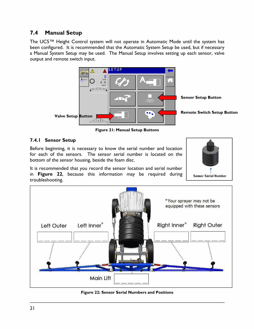
7.4 Manual Setup
The UC5™ Height Control system will not operate in Automatic Mode until the system has been configured. It is recommended that the Automatic System Setup be used, but if necessary a Manual System Setup may be used. The Manual Setup involves setting up each sensor, valve output and remote switch input.
Figure 21: Manual Setup Buttons
7.4.1 Sensor Setup
Before beginning, it is necessary to know the serial number and location for each of the sensors. The sensor serial number is located on the bottom of the sensor housing, beside the foam disc.
It is recommended that you record the sensor location and serial number in Figure 22, because this information may be required during troubleshooting.
Figure 22: Sensor Serial Numbers and Positions
Valve Setup Button
Sensor Setup Button
Remote Switch Setup Button
22
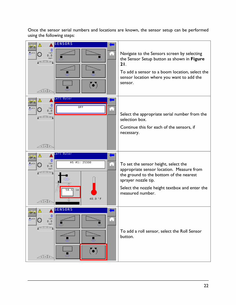
Once the sensor serial numbers and locations are known, the sensor setup can be performed using the following steps:
Navigate to the Sensors screen by selecting the Sensor Setup button as shown in Figure 21.
To add a sensor to a boom location, select the sensor location where you want to add the sensor.
Select the appropriate serial number from the selection box.
Continue this for each of the sensors, if necessary.
To set the sensor height, select the appropriate sensor location. Measure from the ground to the bottom of the nearest sprayer nozzle tip.
Select the nozzle height textbox and enter the measured number.
To add a roll sensor, select the Roll Sensor button.
23
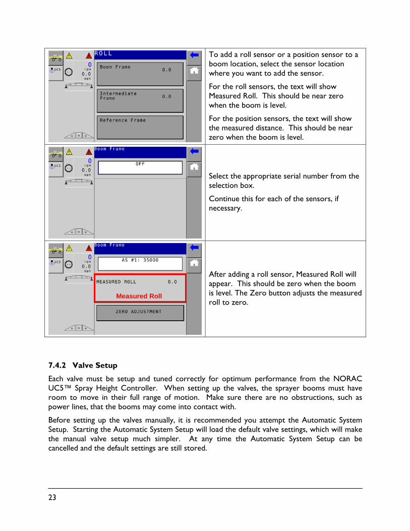
To add a roll sensor or a position sensor to a boom location, select the sensor location where you want to add the sensor.
For the roll sensors, the text will show Measured Roll. This should be near zero when the boom is level.
For the position sensors, the text will show the measured distance. This should be near zero when the boom is level.
Select the appropriate serial number from the selection box.
Continue this for each of the sensors, if necessary.
After adding a roll sensor, Measured Roll will appear. This should be zero when the boom is level. The Zero button adjusts the measured roll to zero.
7.4.2 Valve Setup
Each valve must be setup and tuned correctly for optimum performance from the NORAC UC5™ Spray Height Controller. When setting up the valves, the sprayer booms must have room to move in their full range of motion. Make sure there are no obstructions, such as power lines, that the booms may come into contact with.
Before setting up the valves manually, it is recommended you attempt the Automatic System Setup. Starting the Automatic System Setup will load the default valve settings, which will make the manual valve setup much simpler. At any time the Automatic System Setup can be cancelled and the default settings are still stored.
Measured Roll
24
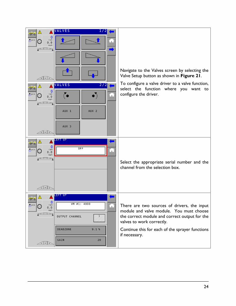
Navigate to the Valves screen by selecting the Valve Setup button as shown in Figure 21.
To configure a valve driver to a valve function, select the function where you want to configure the driver.
Select the appropriate serial number and the channel from the selection box.
There are two sources of drivers, the input module and valve module. You must choose the correct module and correct output for the valves to work correctly.
Continue this for each of the sprayer functions if necessary.

25
7.4.3 Valve Tuning
Each valve has two settings; a Deadzone and Gain setting. The Deadzone relates to the smallest amount of movement the valve can produce. The Gain relates to the maximum speed at which the valve can move the boom function.
A Deadzone and Gain parameter exists for each valve. Each valve may be tuned:
Automatically (as part of the Automatic System Setup or Retune).
Automatically (one valve at a time).
Manually.
26
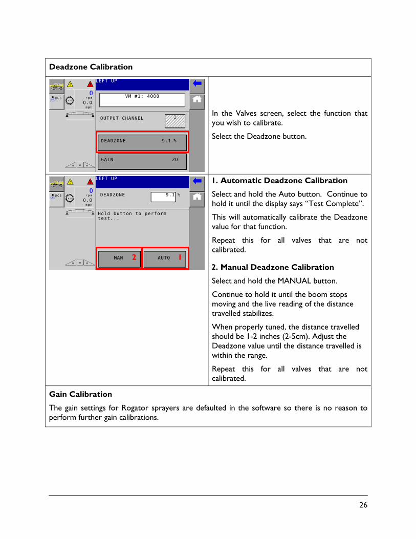
Deadzone Calibration
In the Valves screen, select the function that you wish to calibrate.
Select the Deadzone button.
1. Automatic Deadzone Calibration
Select and hold the Auto button. Continue to hold it until the display says “Test Complete”.
This will automatically calibrate the Deadzone value for that function.
Repeat this for all valves that are not calibrated.
2. Manual Deadzone Calibration
Select and hold the MANUAL button.
Continue to hold it until the boom stops moving and the live reading of the distance travelled stabilizes.
When properly tuned, the distance travelled should be 1-2 inches (2-5cm). Adjust the Deadzone value until the distance travelled is within the range.
Repeat this for all valves that are not calibrated.
Gain Calibration
The gain settings for Rogator sprayers are defaulted in the software so there is no reason to perform further gain calibrations.
2 1
27
8 Diagnostics Menu
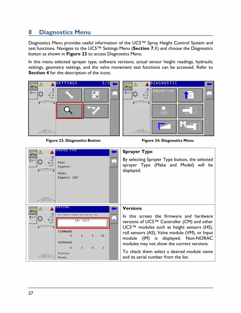
Diagnostics Menu provides useful information of the UC5™ Spray Height Control System and test functions. Navigate to the UC5™ Settings Menu (Section 7.1) and choose the Diagnostics button as shown in Figure 23 to access Diagnostics Menu.
In this menu selected sprayer type, software versions, actual sensor height readings, hydraulic settings, geometry settings, and the valve movement test functions can be accessed. Refer to Section 4 for the description of the icons.
Figure 23: Diagnostics Button
Figure 24: Diagnostics Menu
Sprayer Type
By selecting Sprayer Type button, the selected sprayer Type (Make and Model) will be displayed.
Versions
In this screen the firmware and hardware versions of UC5™ Controller (CM) and other UC5™ modules such as height sensors (HS), roll sensors (AS), Valve module (VM), or Input module (IM) is displayed. Non-NORAC modules may not show the correct versions.
To check them select a desired module name and its serial number from the list.

28
Sensors
The Sensors screen displays raw height sensor readings of connected sensors. The example on the right shows a five-sensor system.
Hydraulics
Hydraulics Diagnostics screens display current hydraulics settings such as Deadzone (DZ), Gain (KP), Base Temperature (BT) for each sprayer function. The final screen displays the current valve block temperature.
Geometry
Geometry Diagnostics screens display current values of geometrical settings such as scale factors (SF) and roll sensor polarities.
Movement Tests
Movement Tests screens provide buttons to test valve movement manually. UC5™ drives a valve to move by selecting and holding a valve function button.
29
9 Maintenance
The NORAC Spray Height Control system requires very little maintenance, but there are a few procedures that will ensure the system continues to work correctly for many years.
Before each day:
It is highly recommended that the sprayer friction pads are greased. To ensure optimum performance this should be done daily. This will ensure the boom is pivoting separately from the sprayer.
Ensure the height sensor breakaway brackets are functioning correctly. Apply grease to the moving parts if necessary, to ensure they return to center after a break-away occurs.
Ensure there is a clean, dry foam disc inserted in each sensor. If it is clogged with dust or other debris, clean it as described below.
At the end of the season:
Replace the oil filter in the NORAC hydraulic manifold annually (AGCO P/N: 556532D1; NORAC P/N: 106285).
Cleaning Ultrasonic Height Sensors:
Remove the foam disc from the sensor and wash it with clean water. Squeeze out excess water and allow the foam disc to dry. The sensor can be used if the foam is wet, however you may not get a valid height reading until it is completely dry.
If the transducer inside the sensor is also dirty, wash it using clean water. Remove the sensor from the bracket and rinse debris from the transducer by pouring water across the face of the sensor. Do not submerge or pressure-wash the sensor. A soft bristle brush can also be used to gently clean the transducer if water alone is not sufficient. Use caution not to scratch or tear the transducer as it is fragile. The sensor should be left to dry with the transducer facing downwards. The sensor can be used if it is wet, however you may not get a valid height reading until it is completely dry. Leaving the control system powered on with the sensor connected and facing down will speed the process of drying the sensor.
Chemicals or compressed air should never be used to clean the sensor.
30
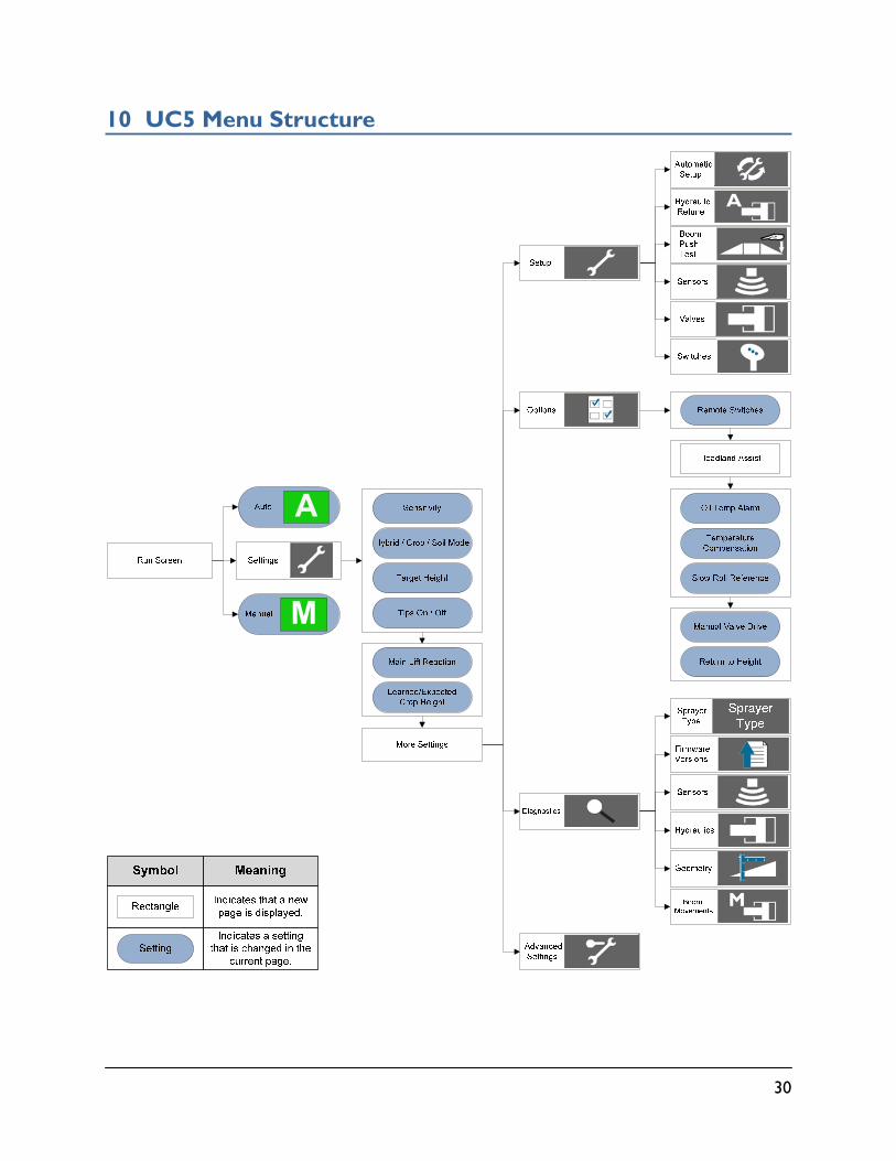
10 UC5 Menu Structure

AGCO - North America 1-877-525-4384