agenda - college of engineering - purdue university · programmable data frame size from 4 to...
TRANSCRIPT
Getting Started With the Stellaris EK-LM4F120XL LaunchPad Workshop- SSI 11 - 1
Synchronous Serial Interface
Introduction
This chapter will introduce you to the capabilities of the Synchronous Serial Interface (SSI) . The
lab uses an Olimex 8x8 LED BoosterPack to explore programming the SPI portion of the SSI. In
order to do the lab you will need to purchase the BoosterPack and make some modification to it.
Agenda
Features...
Introduction to ARM® Cortex™-M4F and Peripherals
Code Composer Studio
Introduction to StellarisWare, Initialization and GPIO
Interrupts and the Timers
ADC12
Hibernation Module
USB
Memory
Floating-Point
BoosterPacks and grLib
Synchronous Serial Interface
UART
µDMA

Chapter Topics
11 - 2 Getting Started With the Stellaris EK-LM4F120XL LaunchPad Workshop- SSI
Chapter Topics
Synchronous Serial Interface ..................................................................................................................11-1
Chapter Topics .......................................................................................................................................11-2
Features and Block Diagram .................................................................................................................11-3
Interrupts and µDMA Operation ...........................................................................................................11-4
Signal Formats .......................................................................................................................................11-5
Lab 11: SPI Bus and the Olimex LED BoosterPack ..............................................................................11-7 Objective............................................................................................................................................11-7 Procedure ...........................................................................................................................................11-8

Features and Block Diagram
Getting Started With the Stellaris EK-LM4F120XL LaunchPad Workshop- SSI 11 - 3
Features and Block Diagram
LM4F120H5QR SSI Features
Block Diagram ...
Four SSI modules. Each with:
Freescale SPI, MICROWIRE or TI Synchronous Serial interfaces
Master or Slave operation
Programmable bit clock rate and pre-scaler
Programmable data frame size from 4 to 16-bits
Separate Tx and Rx FIFOs ( 8 x16-bits )
Interrupts and µDMA support
SSI Block Diagram
Interrupts...
Signal Pinout (n = 0 to 3) …
SSInClk: SSI Module n Clock
SSInFss: SSI Module n Frame Signal
SSInRx: SSI Module n Receive
SSInTx: SSI Module n Transmit
Note that the LM4F120H5QR pins are extensively muxed with other signals.
The Pin Mux Utility can ease theprogramming. See:
www.ti.com/stellarispinmuxutility
Interrupts and µDMA Operation
11 - 4 Getting Started With the Stellaris EK-LM4F120XL LaunchPad Workshop- SSI
Interrupts and µDMA Operation
SSI Interrupts
Operation...
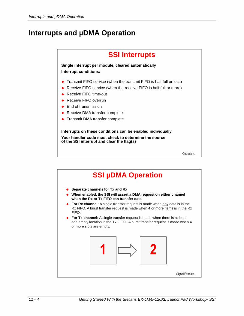
Single interrupt per module, cleared automatically
Interrupt conditions:
Transmit FIFO service (when the transmit FIFO is half full or less)
Receive FIFO service (when the receive FIFO is half full or more)
Receive FIFO time-out
Receive FIFO overrun
End of transmission
Receive DMA transfer complete
Transmit DMA transfer complete
Interrupts on these conditions can be enabled individually
Your handler code must check to determine the source of the SSI interrupt and clear the flag(s)
SSI µDMA Operation
Separate channels for Tx and Rx
When enabled, the SSI will assert a DMA request on either channel
when the Rx or Tx FIFO can transfer data
For Rx channel: A single transfer request is made when any data is in the
Rx FIFO. A burst transfer request is made when 4 or more items is in the Rx
FIFO.
For Tx channel: A single transfer request is made when there is at least
one empty location in the Tx FIFO. A burst transfer request is made when 4
or more slots are empty.
Signal Formats...
1 2
Signal Formats
Getting Started With the Stellaris EK-LM4F120XL LaunchPad Workshop- SSI 11 - 5
Signal Formats
Freescale SPI Signal Formats
TI Signal Formats ...
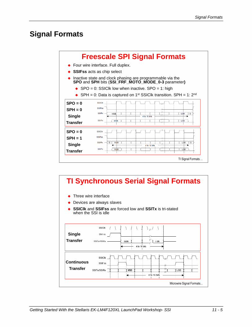
Four wire interface. Full duplex.
SSIFss acts as chip select
Inactive state and clock phasing are programmable via the SPO and SPH bits (SSI_FRF_MOTO_MODE_0-3 parameter)
SPO = 0: SSIClk low when inactive. SPO = 1: high
SPH = 0: Data is captured on 1st SSIClk transition. SPH = 1: 2nd
SPO = 0
SPH = 0
Single
Transfer
SPO = 0
SPH = 1
Single
Transfer
TI Synchronous Serial Signal Formats
Microwire Signal Formats...
Three wire interface
Devices are always slaves
SSIClk and SSIFss are forced low and SSITx is tri-stated when the SSI is idle
Single
Transfer
Continuous
Transfer
Signal Formats
11 - 6 Getting Started With the Stellaris EK-LM4F120XL LaunchPad Workshop- SSI
Microwire Signal Formats
Lab...
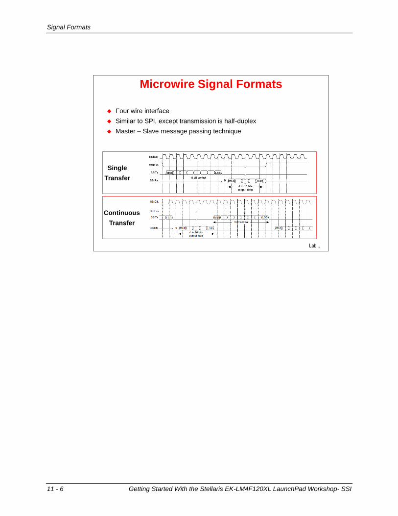
Four wire interface
Similar to SPI, except transmission is half-duplex
Master – Slave message passing technique
Single
Transfer
Continuous
Transfer
Lab 11: SPI Bus and the Olimex LED BoosterPack
Getting Started With the Stellaris EK-LM4F120XL LaunchPad Workshop- SSI 11 - 7
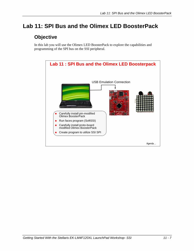
Lab 11: SPI Bus and the Olimex LED BoosterPack
Objective
In this lab you will use the Olimex LED BoosterPack to explore the capabilities and
programming of the SPI bus on the SSI peripheral.
Lab 11 : SPI Bus and the Olimex LED Boosterpack
Carefully install pin-modified Olimex BoosterPack
Run faces program (SoftSSI)
Carefully install proto-board modified Olimex BoosterPack
Create program to utilize SSI SPI
USB Emulation Connection
Agenda ...

Lab 11: SPI Bus and the Olimex LED BoosterPack
11 - 8 Getting Started With the Stellaris EK-LM4F120XL LaunchPad Workshop- SSI
Procedure
Hardware
1. If you want to do this lab, you’re going to need a BoosterPack with a SPI connection. I
chose the Olimex 8x8 LED BoosterPack:
(https://www.olimex.com/Products/MSP430/Booster/MSP430-LED8x8-
B00STERPACK/ ).
This BoosterPack is also available from Mouser Electronics
(http://www.mouser.com/new/olimex/olimexLED8x8/ )
The LED BoosterPack is cheap and fun, but there are two issues with it out of the box.
The first is that it has male Molex pins rather than Molex female connectors. You can get
two of these
(http://www.mouser.com/ProductDetail/FCI/66951-
010LF/?qs=sGAEpiMZZMs%252bGHln7q6pmxAVkKtO
EC39jD0m1rF2xGE%3d ) and solder them directly to the
male pins. This way you can import, build and run the
“faces” program located at C:\StellarisWare\boards\ek-lm4f120xl-
boost-olimex-8x8
This program is pretty cool but it has one little issue, which
brings us back to the second problem with the Olimex
BoosterPack. The pin-out on the Olimex BoosterPack does
not match with any of the SSI module pin-sets on the
Stellaris LaunchPad board (it actually matches an early
version of the MSP430 LaunchPad).
So the author of the “faces” program did what any good engineer would do, they made it
work … with a software SPI port (SoftSSI). The programming of SoftSSI is virtually the
same as programming the actual hardware, but for the purposes of this lab, that’s not
good enough.
2. So we need to connect the pins on the Olimex BoosterPack to the female headers that will
mount on top of the LaunchPad board. Any small perf-board will do, but Joe’s Bytes
( http://joesbytes.com/10-ti-msp430-launchpad-mini-proto-board.html ) has a nice proto-
board that fits perfectly. I soldered the female headers on one side of the board in one
direction and the Olimex BoosterPack on the other side with a 90 degree turn.

Lab 11: SPI Bus and the Olimex LED BoosterPack
Getting Started With the Stellaris EK-LM4F120XL LaunchPad Workshop- SSI 11 - 9
3. Comparing the Olimex BoosterPack schematic found at
https://www.olimex.com/Products/MSP430/Booster/MSP430-LED8x8-
B00STERPACK/resources/MSP430-LED-BOOSTERPACK-schematic.pdf to the
Stellaris LaunchPad schematic, I came up with the following connections for the proto-
board (There are a number of possible solutions here). Bear in mind that the correct way
to number the BoosterPack pins is 1 to 10 from the top of the board to the bottom.
Olimex
Header
Pin
Olimex
Function
LaunchPad
Header Pin
LM4F120H5QR
Pin Name
Pin
Function
J1-7 SR_SCK J2-10 PA2 SSI0CLK
J1-6 SR_LATCH J2-9 PA3 SSI0Fss
J2-7 SR_DATA_IN J1-8 PA5 SSI0Tx
J1-2 A_IN J2-3 PE0 AIN3
J1-3 BUZ_PIN1 J1-9 PA6 GPIO
J1-4 BUZ_PIN2 J1-10 PA7 GPIO
J2-1 Ground J2-1 Ground -
J1-1 Vcc J1-1 Vcc -
4. While you’ve got the Olimex BoosterPack schematic out, take a look at the circuit.
You’ll see that the board is pretty simple; 16-bits of shift register, a Darlington seven
transistor array (for drive strength) plus one more single transistor to make 8 and the 8x8
LED array. In order for the LEDs to light properly, the upper byte of the 16-bit word
must be the bit-reversed version of the lower byte. That will be done in software.
Since this lab concerns the SPI port, we’re going to ignore the connections for the mic
and buzzer.
Faces Code
5. If you have one of the Olimex BoosterPacks and have connected the female headers to it,
carefully connect it to your LaunchPad board. In Code Composer, import the faces
project from C:\StellarisWare\boards\ek-lm4f120xl-boost-olimex-8x8 into your workspace. Build, load and run the project. Poke around in the code if you like,
but we’ll go into detail building Lab11 that uses the SSI peripheral instead of the SoftSSI.
When you’re done, close the faces project.
Disconnect your LaunchPad board from the USB port, carefully remove the Olimix
BoosterPack and re-connect your LaunchPad.

Lab 11: SPI Bus and the Olimex LED BoosterPack
11 - 10 Getting Started With the Stellaris EK-LM4F120XL LaunchPad Workshop- SSI
Import Lab11
6. If you have a proto-board modified Olimex BoosterPack, carefully connect it to the
LaunchPad with the expansion pins towards the top of the LaunchPad as shown below.
You may need to bend the power measurement jumper out of the way slightly:
7. Maximize Code Composer. Import Lab11 with the settings shown below. Make sure the
Copy projects into workspace checkbox is not checked and click Finish.

Lab 11: SPI Bus and the Olimex LED BoosterPack
Getting Started With the Stellaris EK-LM4F120XL LaunchPad Workshop- SSI 11 - 11
8. Expand the project and open main.c for editing. Place the following includes at the top
of the file:
#include "inc/hw_memmap.h"
#include "inc/hw_ssi.h"
#include "inc/hw_types.h"
#include "driverlib/ssi.h"
#include "driverlib/gpio.h"
#include "driverlib/pin_map.h"
#include "driverlib/sysctl.h"
We’re going to need all the regular include files along with the ones that give us access to
the SSI peripheral.
9. Skip a line for spacing and add the next three lines:
#define NUM_SSI_DATA 8 const unsigned char ulDataTx[NUM_SSI_DATA] = {0x88, 0xF8, 0xF8, 0x88, 0x01, 0x1F, 0x1F, 0x01}; unsigned short g_pusTxBuffer[16];
The “third” line is really part of the second one. This array of 8-bit numbers defines
which of the LEDs in the array will be on or off in the following fashion, where red is on
and the open circle is off. The last line defines our transmit buffer:
{A7-0, B7-0, C7-0, D7-0, E7-0, F7-0, G7-0, H7-0}
TOP
H G F E D C B A
7
0
Lab 11: SPI Bus and the Olimex LED BoosterPack
11 - 12 Getting Started With the Stellaris EK-LM4F120XL LaunchPad Workshop- SSI
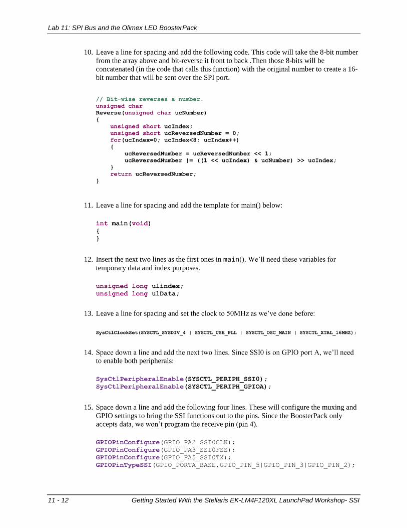
10. Leave a line for spacing and add the following code. This code will take the 8-bit number
from the array above and bit-reverse it front to back .Then those 8-bits will be
concatenated (in the code that calls this function) with the original number to create a 16-
bit number that will be sent over the SPI port.
// Bit-wise reverses a number.
unsigned char
Reverse(unsigned char ucNumber)
{
unsigned short ucIndex;
unsigned short ucReversedNumber = 0;
for(ucIndex=0; ucIndex<8; ucIndex++)
{
ucReversedNumber = ucReversedNumber << 1;
ucReversedNumber |= ((1 << ucIndex) & ucNumber) >> ucIndex;
}
return ucReversedNumber;
}
11. Leave a line for spacing and add the template for main() below:
int main(void)
{
}
12. Insert the next two lines as the first ones in main(). We’ll need these variables for
temporary data and index purposes.
unsigned long ulindex;
unsigned long ulData;
13. Leave a line for spacing and set the clock to 50MHz as we’ve done before:
SysCtlClockSet(SYSCTL_SYSDIV_4 | SYSCTL_USE_PLL | SYSCTL_OSC_MAIN | SYSCTL_XTAL_16MHZ);
14. Space down a line and add the next two lines. Since SSI0 is on GPIO port A, we’ll need
to enable both peripherals:
SysCtlPeripheralEnable(SYSCTL_PERIPH_SSI0);
SysCtlPeripheralEnable(SYSCTL_PERIPH_GPIOA);
15. Space down a line and add the following four lines. These will configure the muxing and
GPIO settings to bring the SSI functions out to the pins. Since the BoosterPack only
accepts data, we won’t program the receive pin (pin 4).
GPIOPinConfigure(GPIO_PA2_SSI0CLK);
GPIOPinConfigure(GPIO_PA3_SSI0FSS);
GPIOPinConfigure(GPIO_PA5_SSI0TX);
GPIOPinTypeSSI(GPIO_PORTA_BASE,GPIO_PIN_5|GPIO_PIN_3|GPIO_PIN_2);
Lab 11: SPI Bus and the Olimex LED BoosterPack
Getting Started With the Stellaris EK-LM4F120XL LaunchPad Workshop- SSI 11 - 13
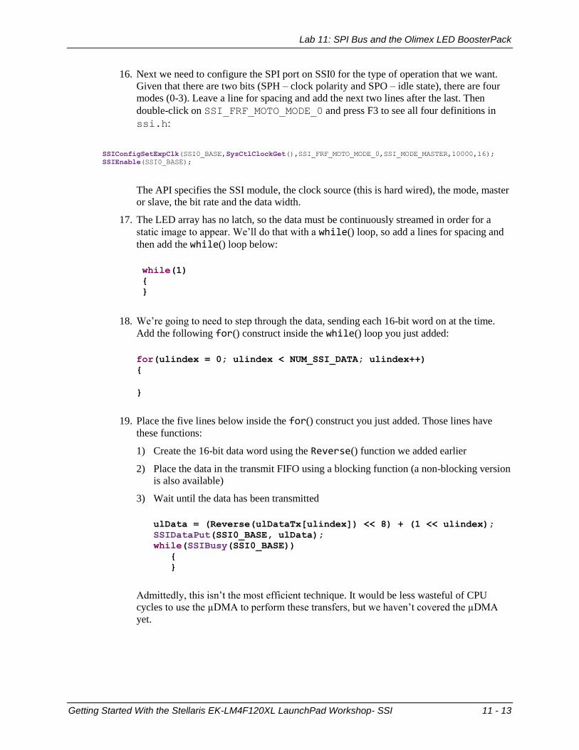
16. Next we need to configure the SPI port on SSI0 for the type of operation that we want.
Given that there are two bits (SPH – clock polarity and SPO – idle state), there are four
modes (0-3). Leave a line for spacing and add the next two lines after the last. Then
double-click on SSI_FRF_MOTO_MODE_0 and press F3 to see all four definitions in
ssi.h:
SSIConfigSetExpClk(SSI0_BASE,SysCtlClockGet(),SSI_FRF_MOTO_MODE_0,SSI_MODE_MASTER,10000,16);
SSIEnable(SSI0_BASE);
The API specifies the SSI module, the clock source (this is hard wired), the mode, master
or slave, the bit rate and the data width.
17. The LED array has no latch, so the data must be continuously streamed in order for a
static image to appear. We’ll do that with a while() loop, so add a lines for spacing and
then add the while() loop below:
while(1)
{
}
18. We’re going to need to step through the data, sending each 16-bit word on at the time.
Add the following for() construct inside the while() loop you just added:
for(ulindex = 0; ulindex < NUM_SSI_DATA; ulindex++)
{
}
19. Place the five lines below inside the for() construct you just added. Those lines have
these functions:
1) Create the 16-bit data word using the Reverse() function we added earlier
2) Place the data in the transmit FIFO using a blocking function (a non-blocking version
is also available)
3) Wait until the data has been transmitted
ulData = (Reverse(ulDataTx[ulindex]) << 8) + (1 << ulindex);
SSIDataPut(SSI0_BASE, ulData);
while(SSIBusy(SSI0_BASE))
{
}
Admittedly, this isn’t the most efficient technique. It would be less wasteful of CPU
cycles to use the µDMA to perform these transfers, but we haven’t covered the µDMA
yet.

Lab 11: SPI Bus and the Olimex LED BoosterPack
11 - 14 Getting Started With the Stellaris EK-LM4F120XL LaunchPad Workshop- SSI
Build and Load
20. Build and load the code. If you have errors, compare your main.c to the code below:
#include "inc/hw_memmap.h"
#include "inc/hw_ssi.h"
#include "inc/hw_types.h"
#include "driverlib/ssi.h"
#include "driverlib/gpio.h"
#include "driverlib/pin_map.h"
#include "driverlib/sysctl.h"
#define NUM_SSI_DATA 8
const unsigned char ulDataTx[NUM_SSI_DATA] =
{0x88, 0xF8, 0xF8, 0x88, 0x01, 0x1F, 0x1F, 0x01};
unsigned short g_pusTxBuffer[16];
// Bit-wise reverses a number.
unsigned char
Reverse(unsigned char ucNumber)
{
unsigned short ucIndex;
unsigned short ucReversedNumber = 0;
for(ucIndex=0; ucIndex<8; ucIndex++)
{
ucReversedNumber = ucReversedNumber << 1;
ucReversedNumber |= ((1 << ucIndex) & ucNumber) >> ucIndex;
}
return ucReversedNumber;
}
int main(void)
{
unsigned long ulindex;
unsigned long ulData;
SysCtlClockSet(SYSCTL_SYSDIV_4 | SYSCTL_USE_PLL | SYSCTL_OSC_MAIN | SYSCTL_XTAL_16MHZ);
SysCtlPeripheralEnable(SYSCTL_PERIPH_SSI0);
SysCtlPeripheralEnable(SYSCTL_PERIPH_GPIOA);
GPIOPinConfigure(GPIO_PA2_SSI0CLK);
GPIOPinConfigure(GPIO_PA3_SSI0FSS);
GPIOPinConfigure(GPIO_PA5_SSI0TX);
GPIOPinTypeSSI(GPIO_PORTA_BASE,GPIO_PIN_5|GPIO_PIN_3|GPIO_PIN_2);
SSIConfigSetExpClk(SSI0_BASE,SysCtlClockGet(),SSI_FRF_MOTO_MODE_0,SSI_MODE_MASTER,10000,16);
SSIEnable(SSI0_BASE);
while(1)
{
for(ulindex = 0; ulindex < NUM_SSI_DATA; ulindex++)
{
ulData = (Reverse(ulDataTx[ulindex]) << 8) + (1 << ulindex);
SSIDataPut(SSI0_BASE, ulData);
while(SSIBusy(SSI0_BASE))
{
}
}
}
}
If you’re still having problems you can find this code in the Lab11/ccs folder as
main.txt.

Lab 11: SPI Bus and the Olimex LED BoosterPack
Getting Started With the Stellaris EK-LM4F120XL LaunchPad Workshop- SSI 11 - 15
Run and Test
21. Run the code by clicking the Resume button. You should see “TI” displayed on the LED
array. If you like you can play with the data structure to draw something different. Keep
it clean.
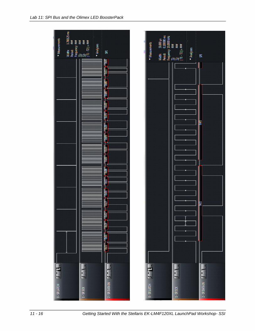
22. If you have a SPI protocol analyzer, now would be a good time to dust it off and take a
look at the serial data stream. These analyzers can save weeks troubleshooting
communication problems. The screen captures on the next page were taken with a Saleae
Logic8 logic analyzer/communications analyzer made by Saleae LLC (www.saleae.com)
Beware of counterfeits!
23. When you’re done, click the Terminate button to return to the CCS Edit perspective.
24. Right-click on Lab11 in the Project Explorer pane and close the project.
25. Disconnect your LaunchPad board from the USB port, carefully remove the Olimix
BoosterPack and re-connect your LaunchPad.
26. Minimize Code Composer Studio.
You’re done.
Lab 11: SPI Bus and the Olimex LED BoosterPack
11 - 16 Getting Started With the Stellaris EK-LM4F120XL LaunchPad Workshop- SSI