agenda corrosion in wet flue gas desulfurization (fgd...
TRANSCRIPT

AGENDA Corrosion in Wet Flue Gas Desulfurization (FGD) Systems
1st Supplemental Project Meeting Charlotte, North Carolina
EPRI Offices: Building 2 Auditorium January 27-28, 2011
TIME Activity Lead Thursday, January 27, 2011 – open meeting (prospective participants welcome) 8:00 am Breakfast All 8:30 am Welcome to EPRI G. Offen – EPRI 8:45 am Introductions & Goals for Meeting T. Hart (Utility
Chairman) -American Electric Power, C. Dene, J. Shingledecker - EPRI
9:00 am Review of Recent Industry Experience with Alloy 2205 in Wet FGD Systems
J. Shingledecker – EPRI
10:00 am Break 10:30 am Content of EPRI Supplemental Project –
Corrosion in Wet FGDs C. Dene, J. Shingledecker – EPRI
11:30 am Q/A about working with EPRI All 12:00 pm Lunch All 1:00 pm Characterizing Chemistry to Help
Understand Corrosion Issues C. Dene – EPRI G. Blythe, URS Corp.
1:45 pm Preliminary Results of Data Collection and Outline of EPRI Root Cause Analysis
B. Tossey – DNV, Columbus
2:30 pm Break All 3:00 pm Group discussion All 5:00 pm Adjourn 7:00 pm Dinner Friday January 28, 2011 – Closed Meeting (open to all funders of the ‘Corrosion in Wet FGDs’ Supplemental Project) 8:00 am Breakfast All 8:15 am Review of workscope, timelines, etc J. Shingledecker, C.
Dene 9:00 am Review of draft deliverable – FGD
Inspection Guideline M. Schwartzwalder – SES
10:00 am Break All 10:30 am Additional questions on root cause analysis B. Tossey – DNV,
Columbus 11:00 am Non Destructive Evaluation (NDE) S. Walker - EPRI 11:30 Other issues All 12:00 pm Lunch All 1:00 pm Wrap-up admin issues, next meetings, etc C. Dene, J.
Shingledecker – EPRI 2:00 pm Adjourn
Corrosion in Wet FGDs
EPRI Welcome
George Offen
Sr. Technical Executive
1st Project Meeting January 27-28, 2011
2© 2011 Electric Power Research Institute, Inc. All rights reserved.
Our Mission…
To conduct research on key issues facing the
electricity sector…on behalf of its members, energy
stakeholders, and society.

3© 2011 Electric Power Research Institute, Inc. All rights reserved.
Our History…
• Founded in 1973
• Independent, nonprofit center for public interest energy and environmental research
• Collaborative resource for the electricity sector
• Major offices in Palo Alto, CA; Charlotte, NC; Knoxville, TN– Laboratories in Knoxville,
Charlotte and Lenox, MAChauncey Starr EPRI Founder

4© 2011 Electric Power Research Institute, Inc. All rights reserved.
Our Members…
• 450+ participants in more than 40 countries
• EPRI members generate more than 90% of the electricity in the United States
• International funding of more than 18% of EPRI’s research, development and demonstrations

5© 2011 Electric Power Research Institute, Inc. All rights reserved.
Investor-Owned63%
International19%
Municipal7%
Cooperative4%
Independent Power Producer
2%
Federal/State5%
December 31, 2010
EPRI Members Breakdown By 2010 Annual Research Portfolio Funding

6© 2011 Electric Power Research Institute, Inc. All rights reserved.
Portfolio Spans the Entire Electricity Sector
Air Quality
Global Climate Change
Land and Groundwater
Occupational Health and Safety
T&D Environmental Issues
Water and Ecosystems
Environment
Transmission Lines and Substations
Grid Operations and Planning
Distribution
Energy Utilization
Cross Cutting Technologies
Power Delivery & Utilization
Advanced Nuclear Technology
Chemistry, Low-Level Waste and Radiation Management
Equipment Reliability
Fuel Reliability
Instrumentation and Control
Material Degradation/Aging
Nondestructive Evaluation and Material Characterization
Risk and Safety Management
Used Fuel and High-Level Waste Management
Nuclear Power
Advanced Coal Plants, Carbon Capture and Storage
Combustion Turbines
Environmental Controls
Generation Planning
Major Component Reliability
Operations and Maintenance
Renewables
Generation

7© 2011 Electric Power Research Institute, Inc. All rights reserved.
EPRI’s Governance and Advisory Structure
Research Advisory Committee
Board of Directors
Generation Sector Council
Nuclear Sector Council
Power Delivery & Utilization Council
Environment Sector Council
Program Committees
Program Committees
Program Committees
Area Councils
Task Forces
Communications Marketing Council
Technology Management Committee
Advisory Council

8© 2011 Electric Power Research Institute, Inc. All rights reserved.
Help Move Technologies to the Commercialization Stage…
Our Role…
Technology Accelerator!
9© 2011 Electric Power Research Institute, Inc. All rights reserved.
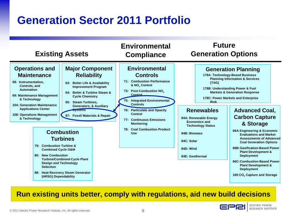
Generation Planning
Renewables Advanced Coal, Carbon Capture
& Storage
178A: Technology-Based Business Planning Information & Services (TAG)
178B: Understanding Power & Fuel Markets & Generation Response
178C: Power Markets and Enterprise Risk
84A: Renewable Energy Economics and Technology Status
84B: Biomass
84C: Solar
84D: Wind
84E: Geothermal
66A:Engineering & Economic Evaluations and Market Assessments of Advanced Coal Generation Options
66B:Gasification-Based Power Plant Development & Deployment
66C:Combustion-Based Power Plant Development & Deployment
165:CO2 Capture and Storage
Environmental Controls
71: Combustion Performance & NOx Control
73: Post-Combustion NOx
Control
75: Integrated Environmental Controls
76: Particulate and Opacity Control
77: Continuous Emissions Monitoring
78: Coal Combustion Product Use
Generation Sector 2011 Portfolio
Major Component Reliability
Operations and Maintenance
68: Instrumentation, Controls, and Automation
69: Maintenance Management & Technology
104: Generation Maintenance Applications Center
108: Operations Management & Technology
Combustion Turbines
79: Combustion Turbine & Combined Cycle O&M
80: New Combustion Turbine/Combined-Cycle Plant Design and Technology Selection
88: Heat Recovery Steam Generator (HRSG) Dependability
63: Boiler Life & Availability Improvement Program
64: Boiler & Turbine Steam & Cycle Chemistry
65: Steam Turbines, Generators, & Auxiliary Systems
87: Fossil Materials & Repair
Existing AssetsEnvironmental
ComplianceFuture
Generation Options
Run existing units better, comply with regulations, aid new build decisions

Antitrust Guidelines for EPRI Meetings
1st Corrosion in Wet FGD Systems Project Meeting
January 27-28, 2011

11© 2011 Electric Power Research Institute, Inc. All rights reserved.
General Antitrust Rules for Meeting Conduct
• These Guidelines for the 2205 Alloy Meeting participants are not legal advice! They are intended to enhance compliance with the letter and spirit of the antitrust laws.
• No set of guidelines can guarantee immunity from legal problems, but observing the following rules should minimize the potential for straying into questionable antitrust territory.
• If a participant has a question, he or she should contact their own company counsel

12© 2011 Electric Power Research Institute, Inc. All rights reserved.
2205 Alloy Meeting Antitrust Guidelines
Collaborative research to accelerate the competitive deployment of solutions to corrosion issues in wet FGD scrubbers
When and Where
These Guidelines apply before, during, and after the” 2205 Alloy” meetings, and in both formal and informal communications.
Meeting’s Purpose
Why Guidelines?
The antitrust laws apply to EPRI, its members, funders, contractors, and advisors; violations can lead to civil and criminal liability.
13© 2011 Electric Power Research Institute, Inc. All rights reserved.
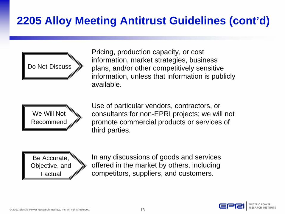
In any discussions of goods and services offered in the market by others, including competitors, suppliers, and customers.
2205 Alloy Meeting Antitrust Guidelines (cont’d)
We Will Not Recommend
Use of particular vendors, contractors, or consultants for non-EPRI projects; we will not promote commercial products or services of third parties.
Be Accurate, Objective, and
Factual
Pricing, production capacity, or cost information, market strategies, business plans, and/or other competitively sensitive information, unless that information is publicly available.
Do Not Discuss

14© 2011 Electric Power Research Institute, Inc. All rights reserved.
2205 Alloy Meeting Antitrust Guidelines (concl.)
For advice from your own Legal Department if you have questions about these guidelines or about a particular situation or activity at EPRI.
Ask
Review and Understand
The “2205 Alloy Meeting” Antitrust Compliance Policy, available at 2205 Alloy meetings and from the EPRI Program Managers.
Do Not Agree With Others
To discriminate against, or refuse to deal with (i.e., “boycott”), a supplier; or to set price, divide markets, or allocate customers.

Corrosion in Wet Flue Gas Desulfurization Systems
Introductions and Meeting Goals
T. Hart Utility Chairman, American Electric Power C. Dene, J. Shingledecker EPRI1st Supplemental Project Meeting EPRI Offices - Charlotte, NC January 27-28, 2011

2© 2011 Electric Power Research Institute, Inc. All rights reserved.
Safety: Evacuation Route Building 2
You are here
Restrooms
Assembly Area (Southeast Corner of Parking Lot)

3© 2011 Electric Power Research Institute, Inc. All rights reserved.
Agenda – January 27, 2011
8:30 am Welcome to EPRI G. Offen – EPRI
8:45 am Introductions & Goals for Meeting T. Hart (Utility Chairman) - American Electric Power, C. Dene, J. Shingledecker - EPRI
9:00 am Review of Recent Industry Experience with Alloy 2205 in Wet FGD Systems
J. Shingledecker – EPRI
10:00 am Break
10:30 am Content of EPRI Supplemental Project – Corrosion in Wet FGDs
C. Dene, J. Shingledecker – EPRI
11:30 am Q/A about working with EPRI All
12:00 pm Lunch All
1:00 pm Characterizing Chemistry to Help Understand Corrosion Issues
C. Dene – EPRIG. Blythe, URS
1:45 pm Preliminary Results of Data Collection and Outline of EPRI Root Cause Analysis
B. Tossey – DNV, Columbus
2:30 pm Break All
3:00 pm Group discussion All
5:00 pm Adjourn
4© 2011 Electric Power Research Institute, Inc. All rights reserved.
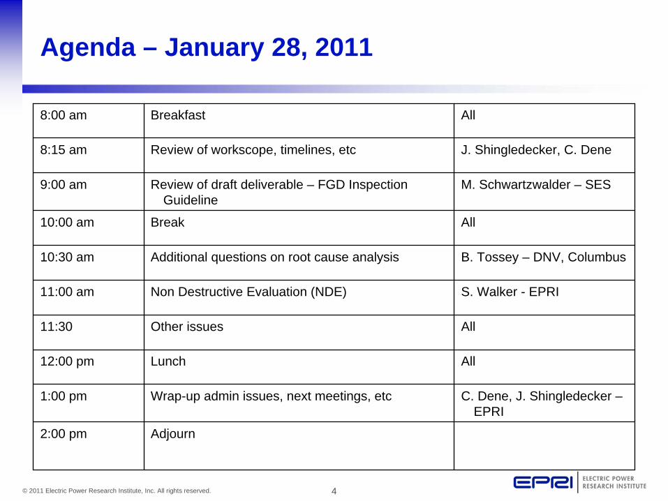
Agenda – January 28, 2011
8:00 am Breakfast All
8:15 am Review of workscope, timelines, etc J. Shingledecker, C. Dene
9:00 am Review of draft deliverable – FGD Inspection Guideline
M. Schwartzwalder – SES
10:00 am Break All
10:30 am Additional questions on root cause analysis B. Tossey – DNV, Columbus
11:00 am Non Destructive Evaluation (NDE) S. Walker - EPRI
11:30 Other issues All
12:00 pm Lunch All
1:00 pm Wrap-up admin issues, next meetings, etc C. Dene, J. Shingledecker – EPRI
2:00 pm Adjourn

5© 2011 Electric Power Research Institute, Inc. All rights reserved.
Goals for Today
• Industry Alert: provide entire industry (not just EPRI members) with critical information on corrosion observations in alloy 2205 FGD absorber vessels
• Introduce and answer questions on a new EPRI supplemental project open to the industry: Corrosion in Wet FGDs
• Technical Presentations:– Role of process chemistry and monitoring– Preliminary results from industry survey
• Industrial Feedback and Discussion– What specific questions do we need to be asking to
address root cause in this project?– What are we missing and what do you need?

6© 2011 Electric Power Research Institute, Inc. All rights reserved.
General Notes
• Attendee List• Presentations• Dinner (tonight – Ciro’s, walking distance from Hilton)• Internet access

7© 2011 Electric Power Research Institute, Inc. All rights reserved.
Together…Shaping the Future of Electricity

Corrosion in Wet Flue Gas Desulfurization (FGD) Systems
Recent Industry Experience with Alloy 2205 Absorber Vessels & Components
J. Shingledecker Senior Project Manager, EPRI Fossil Materials and Repair Program (P87)1st Supplemental Project Meeting EPRI Offices - Charlotte, NC January 27-28, 2011

2© 2011 Electric Power Research Institute, Inc. All rights reserved.
Acknowledgements
EPRI acknowledges the contributions of the following utilities and their personnel who shared their experience, knowledge, and ample visual examples of corrosion damage which made this presentation possible
• American Electric Power (AEP)• Duke Energy• WE Energies

3© 2011 Electric Power Research Institute, Inc. All rights reserved.
Outline
• Materials of Construction in Modern Absorbers• Materials Selection Drivers for New Absorber Vessels• Corrosion Observations
– Proper inspection & nature of observations– Locations
• Welds, base metal, crevice corrosion– Improper fabrication practices– Summary
• Mitigation methods being tried– Alloys– Coatings and tiling– Potential adjustment

4© 2011 Electric Power Research Institute, Inc. All rights reserved.
Where we were EPRI Report 1011913
• In 2005, EPRI completed a survey on the material performance for 12 components in 42 FGD systems including: ductwork, absorbers, recycle tanks, etc.
• For absorber vessels– 36 used stainless steel or carbon steel lined with stainless
steel or nickel-based alloys with few reported major problems• Minor issues with claddings• Corrosion in mixing zones• Metallics being considered as replacements for other organic liners or rubber
– First installation of 2205 was ~2004 (no experience prior)
5© 2011 Electric Power Research Institute, Inc. All rights reserved.
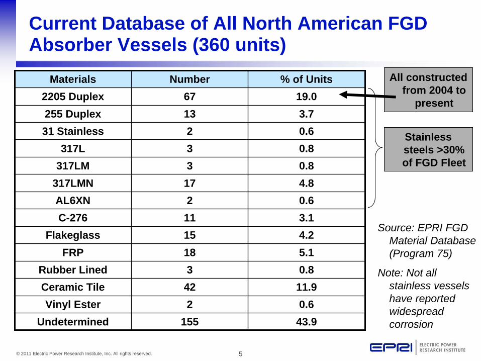
Current Database of All North American FGD Absorber Vessels (360 units)
Materials Number % of Units
2205 Duplex 67 19.0
255 Duplex 13 3.7
31 Stainless 2 0.6
317L 3 0.8
317LM 3 0.8
317LMN 17 4.8
AL6XN 2 0.6
C-276 11 3.1
Flakeglass 15 4.2
FRP 18 5.1
Rubber Lined 3 0.8
Ceramic Tile 42 11.9
Vinyl Ester 2 0.6
Undetermined 155 43.9
All constructed from 2004 to
present
Stainless steels >30% of FGD Fleet
Source: EPRI FGD Material Database (Program 75)
Note: Not all stainless vessels have reported widespread corrosion
6© 2011 Electric Power Research Institute, Inc. All rights reserved.
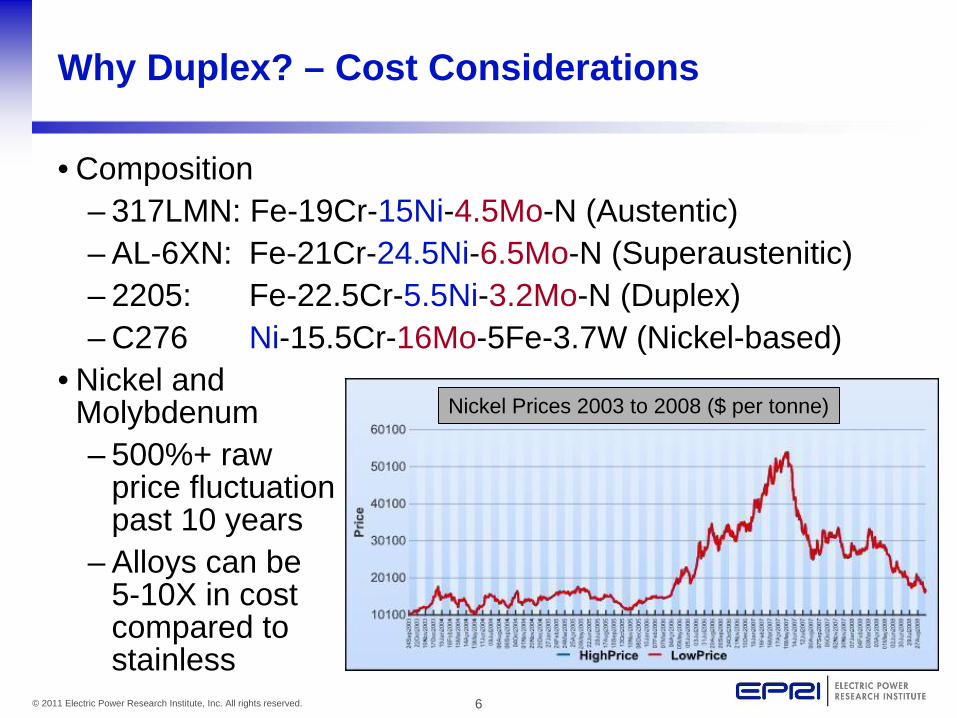
Why Duplex? – Cost Considerations
• Composition– 317LMN: Fe-19Cr-15Ni-4.5Mo-N (Austentic)– AL-6XN: Fe-21Cr-24.5Ni-6.5Mo-N (Superaustenitic)– 2205: Fe-22.5Cr-5.5Ni-3.2Mo-N (Duplex)– C276 Ni-15.5Cr-16Mo-5Fe-3.7W (Nickel-based)
• Nickel and Molybdenum– 500%+ raw
price fluctuation past 10 years
– Alloys can be 5-10X in cost compared to stainless
Nickel Prices 2003 to 2008 ($ per tonne)
7© 2011 Electric Power Research Institute, Inc. All rights reserved.
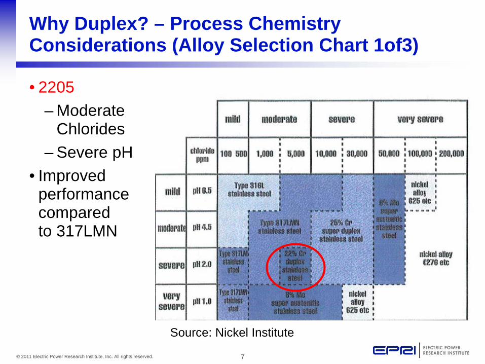
Why Duplex? – Process Chemistry Considerations (Alloy Selection Chart 1of3)
• 2205– Moderate
Chlorides– Severe pH
• Improved performance compared to 317LMN
Source: Nickel Institute
8© 2011 Electric Power Research Institute, Inc. All rights reserved.
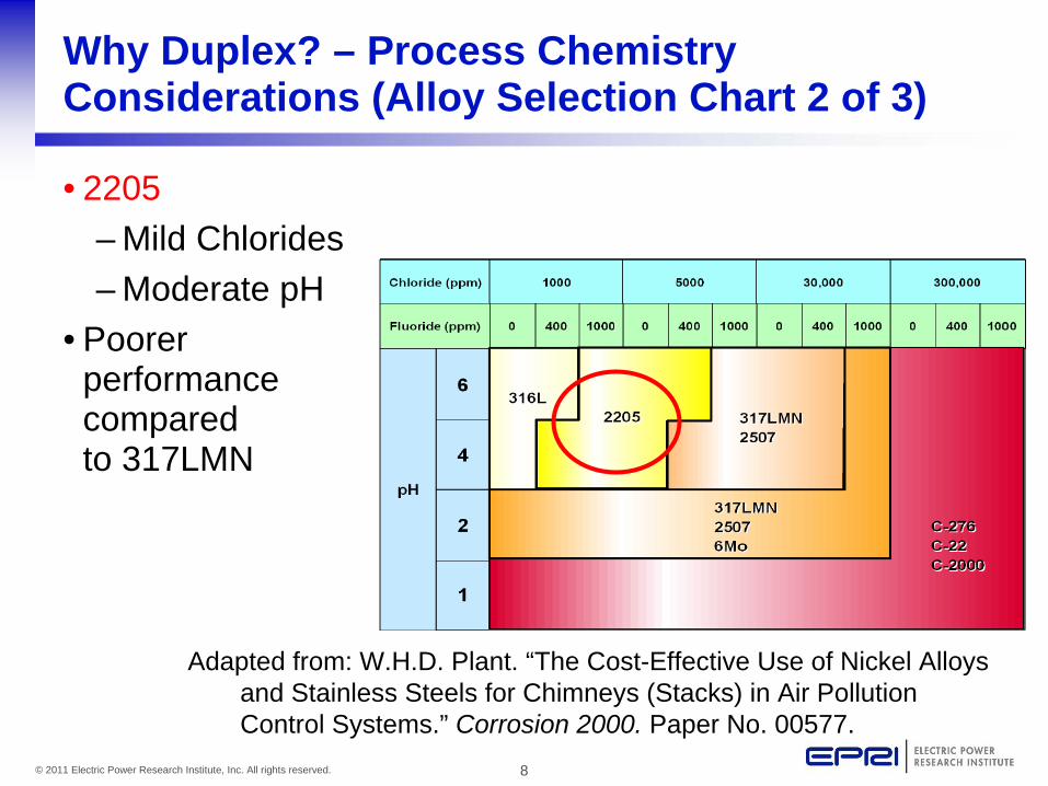
Why Duplex? – Process Chemistry Considerations (Alloy Selection Chart 2 of 3)
• 2205– Mild Chlorides– Moderate pH
• Poorer performance compared to 317LMN
Adapted from: W.H.D. Plant. “The Cost-Effective Use of Nickel Alloys and Stainless Steels for Chimneys (Stacks) in Air Pollution Control Systems.” Corrosion 2000. Paper No. 00577.

9© 2011 Electric Power Research Institute, Inc. All rights reserved.
Why Duplex? – Process Chemistry Considerations (Alloy Selection Chart 3 of 3)
Note pH 5.5-6.5
Flue Gas Desulfurization Materials Guidelines Update: Coating and High Alloys EPRI, Palo Alto, CA: 2001. 1004026
• Chloride Resistance Factor (CRF)
• 2205: 37.9– Moderate
Chlorides– Moderate
pH• Improved
performance compared to 317LMN
10© 2011 Electric Power Research Institute, Inc. All rights reserved.
Summary of Duplex Materials Selection
• Cost compared to stainless steels, nickel-based alloys, or lined vessels– Drivers: alloy composition, raw materials price
fluctuations, thinner walls (higher strength for duplex)• Operational conditions
– Drivers: Moderate Chloride and pH design conditions– 2 out of 3 alloy selection charts show improved
behavior compared to 317LMN
2205 was the winner for alloy selection in 2004-2010

11© 2011 Electric Power Research Institute, Inc. All rights reserved.
Proper Inspection Techniques are Essential to Locating Corrosion
• Draft EPRI Guideline on inspection of wet FGDs has been completed and is available to supplemental project funders
• Before inspection, deposits and scale must be removed to assess underdeposit corrosion
Example of Hard Tenacious Scale
¾” Thick Black Scale

12© 2011 Electric Power Research Institute, Inc. All rights reserved.
Cleaned section of an absorber vessel

13© 2011 Electric Power Research Institute, Inc. All rights reserved.
Scale removal is not enough
• Comparison of the same surface (grit blasted) under direct and indirect lighting
• Standard walkthrough could miss the corrosion
Indirect lighting with LED flashlight reveals corrosion
Direct lighting during typical visual inspection

14© 2011 Electric Power Research Institute, Inc. All rights reserved.
Small surface indications may represent a larger issue (1 of 3)
• Comparison of visual examination and radiograph in same location
Corrosion extends from weld heat-affected-
zone (HAZ) subsurface into base metal

15© 2011 Electric Power Research Institute, Inc. All rights reserved.
Small surface indications may represent a larger issue (2 of 3)
Extensive metal loss with minimal surface
penetration
• Pit size on surface is not a good indication of level of attack
• Pits can ‘wormhole’ through metal• Extreme example: through-wall vessel leak
initiated 12” (300mm) higher inside vessel than external leak location

16© 2011 Electric Power Research Institute, Inc. All rights reserved.
Small surface indications may represent a larger issue (3 of 3)
• Pits are difficult to see• Most metal loss is subsurface• Images taken in base metal from two different units
17© 2011 Electric Power Research Institute, Inc. All rights reserved.
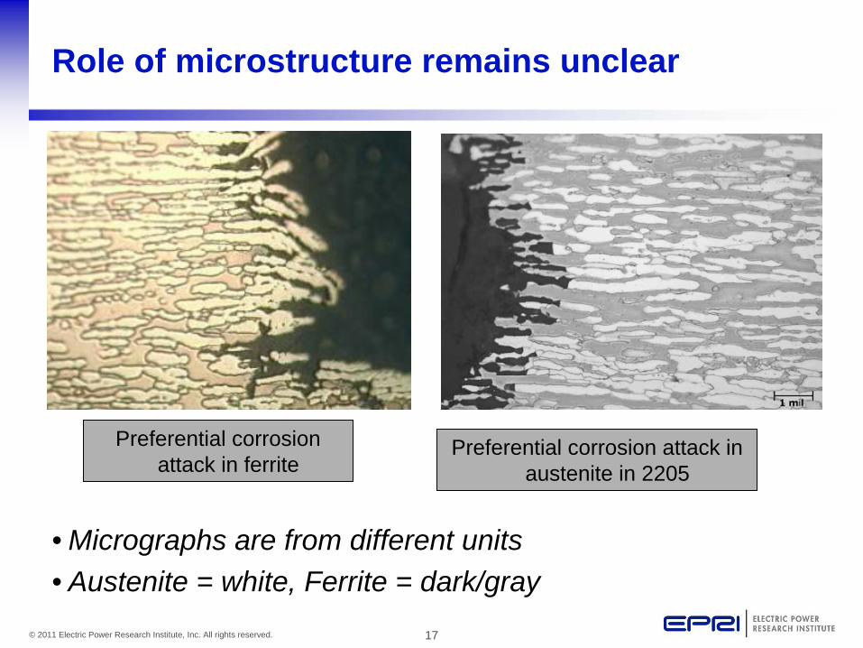
Role of microstructure remains unclear
• Micrographs are from different units• Austenite = white, Ferrite = dark/gray
Preferential corrosion attack in ferrite
Preferential corrosion attack in austenite in 2205

18© 2011 Electric Power Research Institute, Inc. All rights reserved.
Weld metal and heat affected zones are susceptible
Corrosion in weld heat-affected zone causing through wall
failure of 11/16” (17mm) thick vessel wall External view of through-
wall HAZ leaks

19© 2011 Electric Power Research Institute, Inc. All rights reserved.
Weld metal and heat affected zones are susceptible
• Examples of weld pitting and corrosion after ~4 months of service

20© 2011 Electric Power Research Institute, Inc. All rights reserved.
Base metal is susceptible
Extent of removed corrosion pits on absorber vessel walls after ~2 months of service (corrosion was ground out leaving divots)
General appearance of corrosion pits in base metals
Corrosion pit after ~11 months of service (vessel wall)

21© 2011 Electric Power Research Institute, Inc. All rights reserved.
The damage is not restricted to weld metal heat-affected-zone (HAZ) or Alloy 2205
Corrosion in 2205 (lower wall)
Corrosion in 255 (upper wall)
Corrosion in 2205 HAZ extending into base metal

22© 2011 Electric Power Research Institute, Inc. All rights reserved.
Multiple corrosion locations can be observed in the same vessel
• All images taken from multiple inspections on same 2205 absorber vessel (during first 12 months of operation)
Pitting on vertical seam (weld & HAZ)
Pitting in weld metal
Pitting on wall base metal (arrows indicate new pits during 2nd
inspection)
HAZ Pits
23© 2011 Electric Power Research Institute, Inc. All rights reserved.
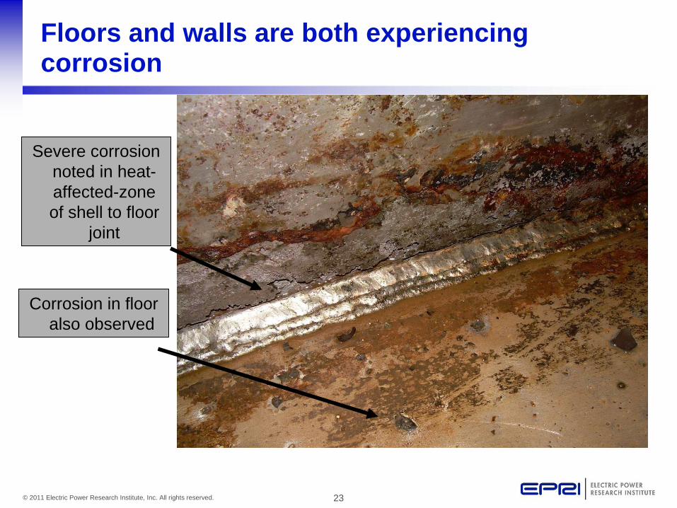
Floors and walls are both experiencing corrosion
Severe corrosion noted in heat- affected-zone of shell to floor
joint
Corrosion in floor also observed

24© 2011 Electric Power Research Institute, Inc. All rights reserved.
Crevice locations are susceptible
Corrosion on Bobcat door
Corrosion at bolted
attachmentCorrosion at manway seal

25© 2011 Electric Power Research Institute, Inc. All rights reserved.
Multiple designs are affected
Dye penetrate reveals extensive corrosion in weld seam of
spray tower
Corrosion in 2205 beam support for Jet Bubble Reactor (JBR)

26© 2011 Electric Power Research Institute, Inc. All rights reserved.
Improper fabrication practices are contributing in some instances (1 of 2)
Corrosion pattern following apparent writing on vessel (improper use of markers)

27© 2011 Electric Power Research Institute, Inc. All rights reserved.
Improper fabrication practices are contributing in some instances (2 of 2)
Corrosion pattern following grinding marks on floor
Iron Contamination
Improper welding sequence may have contributed to weld metal susceptibility (final pass should be on vessel interior)
28© 2011 Electric Power Research Institute, Inc. All rights reserved.
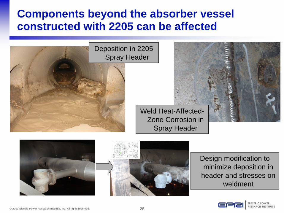
Components beyond the absorber vessel constructed with 2205 can be affected
Weld Heat-Affected- Zone Corrosion in
Spray Header
Design modification to minimize deposition in
header and stresses on weldment
Deposition in 2205 Spray Header

29© 2011 Electric Power Research Institute, Inc. All rights reserved.
Summary of Corrosion Observations
• Locating corrosion is only as good as your inspection techniques– Proper cleaning of scale and deposits– Serious corrosion may only be indicated with small surface
features• Role of microstructure is unclear• Corrosion is affecting:
– Weld metal and heat-affected-zones (HAZ)– Base metal– Regions of improper fabrication techniques– Multiple designs– Times as short as 2 months and through-wall leaks recorded
in less than 1 year of service• Mechanisms reported:
– Crevice corrosion, underdeposit corrosion, MIC (suggested for one case, dismissed by another)

30© 2011 Electric Power Research Institute, Inc. All rights reserved.
Mitigation strategies currently being implemented by industry
• Relining the vessel with Stebbins tile• Weld Repair• Coatings• Potential
Adjustment (PAP)

31© 2011 Electric Power Research Institute, Inc. All rights reserved.
Stebbins Tile Mock-up for 2205 Jet Bubble Reactor Vessel
Tile
Mortar
Intermediate layer coating for thermal expansion
2205 Vessel
Currently considered a ‘permanent’ fix

32© 2011 Electric Power Research Institute, Inc. All rights reserved.
Weld Repair Options in Use Today
• Installation of plate work• Addition of external support (vessel integrity)• Issues
– New additional welds– Full removal of corrosion
products prior to welding
Plate work Repair
External support
33© 2011 Electric Power Research Institute, Inc. All rights reserved.
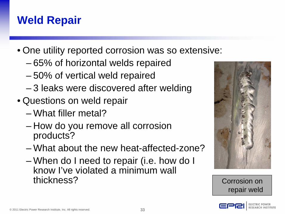
Weld Repair
• One utility reported corrosion was so extensive:– 65% of horizontal welds repaired– 50% of vertical weld repaired– 3 leaks were discovered after welding
• Questions on weld repair– What filler metal?– How do you remove all corrosion
products?– What about the new heat-affected-zone?– When do I need to repair (i.e. how do I
know I’ve violated a minimum wall thickness? Corrosion on
repair weld

34© 2011 Electric Power Research Institute, Inc. All rights reserved.
Potential Adjustment Protection (PAP) System
• Successful in other (older) FGD systems• Not applied to 2205 duplex until 2010• Utility application 2010
– Lab study suggested 2205 should be amenable to approach
– ~1Millions dollars for design & installation – 1 unit– Currently on 2 units

35© 2011 Electric Power Research Institute, Inc. All rights reserved.
External view of PAP System
PAP system anode entry (1 of 6)
PAP system reference electrode (1 of 4)

36© 2011 Electric Power Research Institute, Inc. All rights reserved.
Internal view of PAP System
PAP system center column, radial
supports, perforated deflectors,
six anode assemblies

37© 2011 Electric Power Research Institute, Inc. All rights reserved.
Considerations & Preliminary Performance
• Considerations:– Removal of corrosion prior to installation– Limits accessibility for inspections– Maintenance
• Performance (3 months, 2 units)• Lower than expected reference readings in lower area
• Field testing has showed passivation• Field testing showed insufficient current density to fully passivate lower area of tower
• Evaluations continue• Exploring the use of additional anodes

38© 2011 Electric Power Research Institute, Inc. All rights reserved.
Summary of Mitigation Methods in Use Today
• Shorter-term fixes:– Weld repair– Patch plate repair– Structural support (vessel integrity)– Coatings (still gathering data)
• Long-term solutions– Relining with Stebbin’s tile
• Not yet proven for lining of a metallic 2205 vessel with corrosion already present
– Cladding• Not yet used on large scale but has been used for local
protection in the past (same welding issues as short-term repair)– Potential Adjustment Protection (PAP)
• First installations on 2205 in 2010• Still on a learning curve: passivation has been realized but full
vessel passivation will require additional modifications
39© 2011 Electric Power Research Institute, Inc. All rights reserved.
Overall Summary
• Duplex 2205 is being used extensively in many Wet FGD designs
• Significant corrosion has been observed by multiple utilities utilizing different designs
• Effected areas– Base metal, weld metal, heat-affected-zones, and
areas of improper fabrication– Not limited to absorber vessels– Proper inspection is critical to finding corrosion– Underdeposit corrosion, crevice corrosion, and MIC all
reported mechanisms• Short and long-term mitigation strategies are now being
implemented with varied success

40© 2011 Electric Power Research Institute, Inc. All rights reserved.
Together…Shaping the Future of Electricity

Corrosion in Wet Flue Gas Desulfurization Systems
Content of EPRI Supplemental Project
C. Dene, J. Shingledecker EPRI1st Supplemental Project Meeting EPRI Offices - Charlotte, NC January 27-28, 2011

2© 2011 Electric Power Research Institute, Inc. All rights reserved.
Background (Timeline)
• Widespread reports of corrosion in Wet FGD Systems constructed with duplex 2205
• At the request of the EPRI Generation Council (October 7- 8, 2010) EPRI convened a meeting with utility members in November 4, 2010 (Charlotte, NC)– 47 participants representing 15 members– Meeting goals
• Review industry experience with 2205
• Determine appropriate actions for EPRI & Industry

3© 2011 Electric Power Research Institute, Inc. All rights reserved.
Key Takeaways from EPRI Member 2205 Meeting
• Clearly a widespread issue in 2205• The cost of inspections, temporary fixes, and potential longer-term
solutions is very high both from lost generation and cost of repair• Voice of the members:
– This is a safety issue: We need to alert the industry beyond EPRI membership
– The time for talk is over, (sharing experience can only get us so far) we need action
– We need to collect detailed data on operation, materials, construction practices, and corrosion observations
– Numerous unanswered questions exist and there was general consensus that EPRI should put together a project to address these issues
4© 2011 Electric Power Research Institute, Inc. All rights reserved.
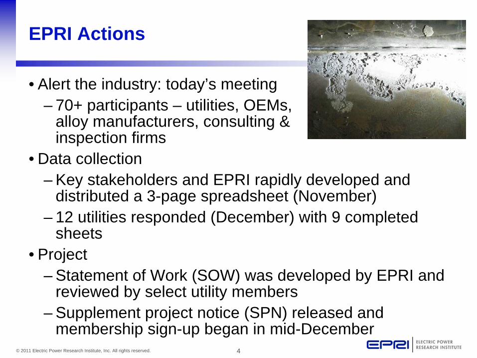
EPRI Actions
• Alert the industry: today’s meeting– 70+ participants – utilities, OEMs,
alloy manufacturers, consulting & inspection firms
• Data collection– Key stakeholders and EPRI rapidly developed and
distributed a 3-page spreadsheet (November)– 12 utilities responded (December) with 9 completed
sheets• Project
– Statement of Work (SOW) was developed by EPRI and reviewed by select utility members
– Supplement project notice (SPN) released and membership sign-up began in mid-December

5© 2011 Electric Power Research Institute, Inc. All rights reserved.
(Some) Key Questions
• Is everyone doing an adequate job inspecting these units? • What is the cause of the corrosion?• Are alloys beyond 2205 in jeopardy?• Do we have consistent fabrication practices across the
industry? – Lots of questions on surface finish, welding, etc
• What are my options for repair and how do they perform?• What about coatings, alternate alloys, etc?
– Are there options for testing without large scale installation?

6© 2011 Electric Power Research Institute, Inc. All rights reserved.
EPRI Response: Corrosion in Wet Flue Gas Desulfurization (FGD) Systems
• Supplemental project launched December 2010• Project Scope:
– Root cause analysis for corrosion found in alloy 2205 in wet FGD systems
– Fabrication guidelines for the use of alloy 2205 and other metallic alloys in wet FGD system
– Repair guidance for metallic FGD systems and components experiencing corrosion
– Corrosion behavior and performance of alternate materials and coatings for wet FGDs
– Information exchange through a Corrosion in FGD Materials Interest Group
7© 2011 Electric Power Research Institute, Inc. All rights reserved.
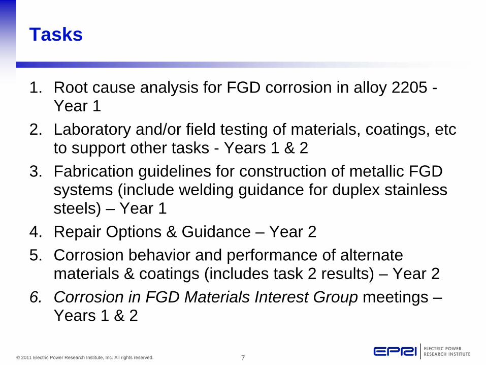
Tasks
1. Root cause analysis for FGD corrosion in alloy 2205 - Year 1
2. Laboratory and/or field testing of materials, coatings, etc to support other tasks - Years 1 & 2
3. Fabrication guidelines for construction of metallic FGD systems (include welding guidance for duplex stainless steels) – Year 1
4. Repair Options & Guidance – Year 25. Corrosion behavior and performance of alternate
materials & coatings (includes task 2 results) – Year 26. Corrosion in FGD Materials Interest Group meetings –
Years 1 & 2

8© 2011 Electric Power Research Institute, Inc. All rights reserved.
Task 1. Root cause analysis for FGD corrosion in alloy 2205 – Year 1
Subtasksa. Develop root cause analysis (RCA) procedureb. Collect data from industryc. Review of relevant literatured. RCA Report & recommendationse. Inspection techniques
Deliverables (Year 1)• Final Report: Inspection Techniques for Corrosion
Damage in Wet FGDs• Final Report: Root cause analysis of alloy 2205
corrosion in wet FGD systems

9© 2011 Electric Power Research Institute, Inc. All rights reserved.
Task 1. Progress
a. Develop root cause analysis (RCA) procedure Presentation later today - we need this group to bring forward as many specific questions as possible to properly do a RCA
b. Collect data from industry Initial spreadsheet collection is complete and analysis is ongoing. Missing and additional information will be collected through site visits, assessments, phone calls, etc.
c. Review of relevant literature Initiated
d. RCA Report & recommendationse. Inspection techniques and guideline
Draft report complete, provided to project funders for review (Jan. 21, 2011)
10© 2011 Electric Power Research Institute, Inc. All rights reserved.
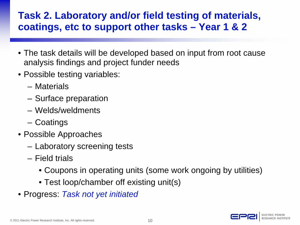
Task 2. Laboratory and/or field testing of materials, coatings, etc to support other tasks – Year 1 & 2
• The task details will be developed based on input from root cause analysis findings and project funder needs
• Possible testing variables:– Materials– Surface preparation– Welds/weldments– Coatings
• Possible Approaches– Laboratory screening tests– Field trials
• Coupons in operating units (some work ongoing by utilities)• Test loop/chamber off existing unit(s)
• Progress: Task not yet initiated

11© 2011 Electric Power Research Institute, Inc. All rights reserved.
Task 2. Laboratory and/or field testing of materials, coatings, etc to support other tasks – Year 1 & 2
• Progress: – Task not yet initiated– Task 1 Root Cause Analysis will assist in defining
areas where more information is needed
Deliverables (Year 2) – Included in Task 5 Report

12© 2011 Electric Power Research Institute, Inc. All rights reserved.
Task 3. Fabrication guidelines for construction of metallic FGD systems – Year 1
• Provide consistent guidelines for proper fabrication practices– Avoid iron contamination– Ensure proper surface preparation
• Provide welding guidance for FGD construction (some conflicting guidance in industry today)– Duplex stainless steels– Stainless steels and nickel-based alloys– Clad construction– Heat input, thickness, welding sequence, filler metal
selection, post-weld inspection requirements

13© 2011 Electric Power Research Institute, Inc. All rights reserved.
Task 3. Fabrication guidelines for construction of metallic FGD systems – Year 1
• Progress: – Task not yet initiated– First discussions with project funders Friday
Deliverables (Year 1)• Final Report: Fabrication guidelines for metallic FGD
systems

14© 2011 Electric Power Research Institute, Inc. All rights reserved.
Task 4. Repair Options & Guidance (includes task 2 results) – Year 2
• Improved weld repair guidance– Post-corrosion cleaning and preparation– Filler metals and processes– Inspection
• Field experience with ‘stop-gap’ measures such as weld repairs and coatings
• Review of experience with Potential Adjustment Protection (PAP)
• Process chemistry/operational changes• Others?

15© 2011 Electric Power Research Institute, Inc. All rights reserved.
Task 4. Repair Options & Guidance (includes task 2 results) – Year 2
• Progress: No action on workplan, currently monitoring these options as information is gained through Interest Group
Deliverables (Year 2)• Final Report: Repair options for corrosion in metallic FGD
systems

16© 2011 Electric Power Research Institute, Inc. All rights reserved.
Task 5. Corrosion behavior and performance of alternate materials & coatings (includes task 2 results) – Year 2
• Laboratory and/or field test results from Task 2• Additional laboratory tests on coatings
– Adherence, thermal stability, embrittlement, surface preparation, etc.
• Progress: – No action yet– Begin to define potential coating solutions of interest
with project funders
Deliverables (Year 2)• Final Report: Corrosion behavior and performance of
alternative materials and coatings

17© 2011 Electric Power Research Institute, Inc. All rights reserved.
Task 6. Corrosion in FGD Materials Interest Group meetings – Years 1 & 2
• Minimum of 2 meetings per year (aim for 3 in first year)• Conduct webcast/conference calls as appropriate for task
items or deliverables which require reviews• Meeting Dates
– 1st Meeting: January 27-28, 2011: EPRI Offices Charlotte, NC
– 2nd Meeting (after agreement with funders): June 20-21, 2011: Orlando, FL (prior to EPRI 2nd Int. Conference on Welding and Fabrication Technology for New Power Plant Components – Nuclear & Fossil)
– 3rd Meeting – Fall/winter 2011– 2012 TBD

18© 2011 Electric Power Research Institute, Inc. All rights reserved.
Summary of Planned Project Deliverables
• Final Report: Inspection Techniques for Corrosion Damage in Wet FGDs Draft Report Available
• Final Report: Root cause analysis of alloy 2205 corrosion in wet FGD systems Work has initiated
• Final Report: Fabrication guidelines for metallic FGD systems
• Final Report: Repair options for corrosion in metallic FGD systems
• Final Report: Corrosion behavior and performance of alternative materials and coatings

19© 2011 Electric Power Research Institute, Inc. All rights reserved.
Project Participation and Details
• Project Cost:– 50k/yr for 2 yrs (100k total)– EPRI members can use
tailored collaboration funds for up to 1/2 of the cost
• Membership:– Open to non-EPRI members– Current membership
• 11 participants committed• Conducting the project:
– With 7 funders Tasks 1 & 6 will be initiated– Additional tasks will initiate based on funding and as
directed and prioritized by project participants
20© 2011 Electric Power Research Institute, Inc. All rights reserved.
Together…Shaping the Future of Electricity

Characterizing FGD Chemistry to Help Understand Corrosion Issues
Gary Blythe, URS Corporation
512-419-5321 / [email protected] Dene, EPRI 650-855-2425 / [email protected]
January 27, 2011

2© 2010 Electric Power Research Institute, Inc. All rights reserved.
• Most of us understand the importance of chlorides, pH, and temperature in pitting corrosion
• Other parameters may also be important
– Manganese [Mn] concentrations by phase
– Oxidation-reduction potential (ORP)
• Direct measure of how chemically oxidizing or reducing is the aqueous environment in the reaction tank
• Can impact what phase Mn, other trace elements report to in FGD slurry (scaling potential)
Why Characterize FGD Chemistry?

3© 2010 Electric Power Research Institute, Inc. All rights reserved.
Change in Mn Forms with pH, ORP (Pourbaix diagram in pure water)
• Mn changes from soluble Mn2+ to insoluble Mnx Oy(Mn4+) as ORP increases at FGD pH
• At a given ORP level, phase of Mn could change between absorber (soluble) and reaction tank (insoluble) with pH variation– Could contribute to
MnO2 scale formation in reaction tank over time

4© 2010 Electric Power Research Institute, Inc. All rights reserved.
Full-scale Data for Mn Partitioning in Reaction Tank Slurry vs. ORP
R2 = 0.78
0%
10%
20%
30%
40%
50%
60%
70%
80%
90%
100%
0 100 200 300 400 500 600 700
ORP, mV
% o
f E
lem
ent
in S
lurr
y L
iqu
or
% Mn in Liquor
% Mn in Liquor -Outliers:
Site H Unit 3
Site M Units 3 & 4

5© 2010 Electric Power Research Institute, Inc. All rights reserved.
Full-scale Data for Mn Partitioning in Reaction Tank Slurry vs. ORP – for One Unit
0%
10%
20%
30%
40%
50%
60%
70%
80%
90%
100%
0 50 100 150 200 250 300 350 400 450 500
ORP, mV
% o
f E
lem
ent
in S
lurr
y L
iqu
or
% Mn in Liquor

6© 2010 Electric Power Research Institute, Inc. All rights reserved.
Where Does the Mn in FGD Slurry Come from?
• EPRI trace element balance data for 7 coal-fired units with limestone wet FGD systems:– Average Mn balance closure around units – 85%– Average calculated contribution of limestone to Mn
found in FGD output streams – 107%– Results suggest ~all Mn comes from limestone
• EPRI data for Mn concentrations in limestone from 8 LSFO wet FGD systems:– Range: 31 – 349 ppm– Average: 125 ppm– Standard Deviation: 99 ppm– Anecdotal data show even greater variability (3 ppm to
>1000 ppm)

7© 2010 Electric Power Research Institute, Inc. All rights reserved.
What are Mn Concentrations in FGD Reaction Tank Slurry?
• Liquid phase (EPRI data from 8 LSFO systems):
– Range: 0.009 ppm (9 ppb) to 302 ppm– Average, standard deviation: 44 ppm ± 79 ppm– Cycles up like chloride due to evaporation, liquor return
from dewatering• Solid phase (same 8 systems):
– Range: 6 to 181 ppm– Average, standard deviation: 49 ppm ± 51 ppm– Tends to concentrate in fine solids, gets recycled to
absorber with hydroclone overflow return
8© 2010 Electric Power Research Institute, Inc. All rights reserved.
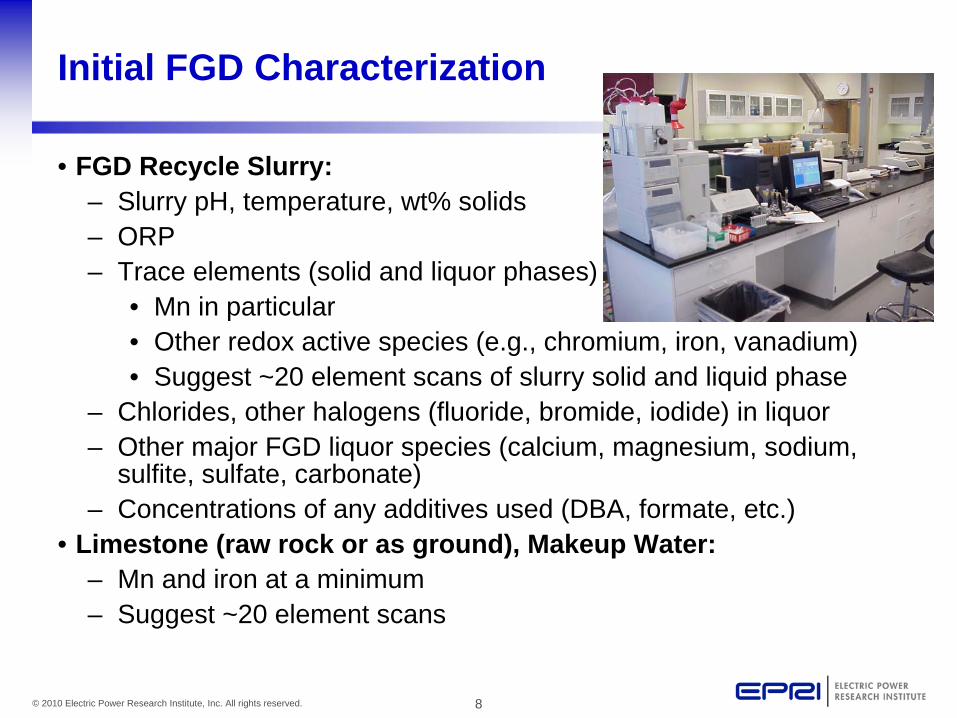
Initial FGD Characterization
• FGD Recycle Slurry:– Slurry pH, temperature, wt% solids – ORP– Trace elements (solid and liquor phases)
• Mn in particular• Other redox active species (e.g., chromium, iron, vanadium)• Suggest ~20 element scans of slurry solid and liquid phase
– Chlorides, other halogens (fluoride, bromide, iodide) in liquor – Other major FGD liquor species (calcium, magnesium, sodium,
sulfite, sulfate, carbonate)– Concentrations of any additives used (DBA, formate, etc.)
• Limestone (raw rock or as ground), Makeup Water:– Mn and iron at a minimum– Suggest ~20 element scans
9© 2010 Electric Power Research Institute, Inc. All rights reserved.
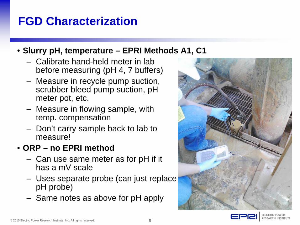
FGD Characterization
• Slurry pH, temperature – EPRI Methods A1, C1– Calibrate hand-held meter in lab
before measuring (pH 4, 7 buffers)– Measure in recycle pump suction,
scrubber bleed pump suction, pH meter pot, etc.
– Measure in flowing sample, with temp. compensation
– Don’t carry sample back to lab to measure!
• ORP – no EPRI method– Can use same meter as for pH if it
has a mV scale– Uses separate probe (can just replace
pH probe)– Same notes as above for pH apply

10© 2010 Electric Power Research Institute, Inc. All rights reserved.
Additional Notes about ORP Measurement
• URS has had good luck with Beckman (BKA57197 [silver/silver chloride reference]) probe
• Measurements are relative to the reference electrode, so be sure to note reference electrode type with data
• Most meters do not have a calibration adjustment, but ORP standards are available– Zobell solution – 231 mV with Ag/AgCl– Thermo Orion standard – 215 mV with Ag/AgCl– Check before and after reading
• Measure at the same time, place as pH• Do not take reading until temp. readout is steady, matches temp.
during pH measurement– ORP reading may not ever steady out – just read value when
temp. readout is steady– Measurement is not exact, ±10-20 mV is adequate

11© 2010 Electric Power Research Institute, Inc. All rights reserved.
Sampling for Trace Elements (including Mn)
• Sample at same location as pH, temperature, ORP measurements (and at the same time)
• Filter sample as soon as possible after collection to preserve partitioning (do not send whole slurry to off-site lab to analyze!)
– Recommend filtering through 0.45 µM pore size filter, dry at 60oC– Preserve liquor at plant lab to 1% HNO3 using Trace Metal Grade
acid (preserved sample requires HazMat shipping)– Collect slurry and ship acidified liquor sample in pre-cleaned EPA
sample bottles• 3rd party lab may provide bottles
– Collect and ship solid phase in clean, air-tight, sealed container

12© 2010 Electric Power Research Institute, Inc. All rights reserved.
Sampling/Analysis Methods for Balance of FGD Samples (EPRI FGD Chemistry and Analytical Methods Handbook, 1013347)
Method TypeMethod
No. Method Description
Gravimetric Percent Solids/Percent Moisture Methods
F1 Gravimetric Method for Weight Percent Solids in Wet Scrubber Slurries
F3 Cassia Flask Density Method for Weight Percent Solids
F6 Thermogravimetric Determination of Solid Concentration and Gypsum Purity
Atomic Absorption (AA) Methods
H1 Calcium, Magnesium, Sodium, Potassium, Iron, Manganese, and Aluminum Analyses by Flame AA
Ion Chromatograph (IC) Methods
I2 Analysis by IC of Fluoride, Chloride, Sulfite, Sulfate, Thiosulfate, and Total Sulfur in Scrubber Liquors and Total Sulfur in Scrubber Solids
Calcium/Magnesium Methods
J1 Calcium and Magnesium Analysis in Limestone and Scrubber Solids by EDTA Titration
J2 Calcium and Magnesium Analysis in Scrubber Liquor by EDTA Titration

13© 2010 Electric Power Research Institute, Inc. All rights reserved.
Sampling/Analysis Methods for Balance of FGD Samples (EPRI FGD Chemistry and Analytical Methods Handbook, 1013347)[continued]
Method TypeMethod No. Method Description
Sulfite Methods M2 Sulfite Analysis in Scrubber Liquors and Slurry Solids by Iodine-Thiosulfate Titration
Carbonate Methods N3 Alkalinity (Carbonate, Oxide, and Hydroxide) Measurement by Acid-Base Titration
N4 Coulometric Determination of Carbonate in Liquids and Solids
Chloride Methods O1 Chloride Analysis in FGD Liquors by Mercuric Nitrate Titration
O4 Chloride Analysis by Silver Nitrate Titration Using a Chloride Ion-Specific Electrode
O5 Extraction of Chloride from Gypsum, and pH and Percent Inerts Determination of Gypsum
Fluoride Methods P1 Fluoride Analysis in Solid and Liquid Samples by Ion Selective Electrode
Organic Acid Methods S1 Buffer Capacity Titration

14© 2010 Electric Power Research Institute, Inc. All rights reserved.
Ongoing FGD Characterization (straw man)
• ORP measurement at same frequency as routine FGD pH instrument calibration (1-2 times/week; get data at varied unit load, coal S)
• Routine tracking of Mn in limestone (weekly at first?)– Consider submitting NIST SRM 1c limestone for QC
• Trace metals concentrations, partitioning in FGD slurry (Mn weekly, balance of elements monthly?)
• Chloride – most plants routinely measure to adjust blow down rates anyway
• Liquor-phase sulfite – may need to track (daily?) if lowering ORP to avoid Mn scale formation

15© 2010 Electric Power Research Institute, Inc. All rights reserved.
Ongoing FGD Characterization (Table)
Analyte Frequency
ORP in FGD slurry 1-2/wk. (get data at varied load, coal S)
Mn in limestone 1/wk.
Mn in FGD slurry solids and liquor 1/wk.
Other trace elements in FGD slurry solids and liquor
1/mo.
Chloride in FGD liquor 2/wk.
Sulfite in FGD liquor 1-5/wk.

1st Supplemental Project Meeting
EPRI Root Cause Analysis
Brett Tossey (DNV)Gerry Koch (DNV)Arun Agrawal (DNV)
Corrosion in Wet Flue Gas Desulfurization (FGD) Systems
January 27th-28th, 2011

2© 2011 Electric Power Research Institute, Inc. All rights reserved.
Outline
• EPRI Root Cause Analysis Workscope
• Preliminary review of collected spreadsheets
• Preliminary literature review
• Structure of root cause analysis/feedback

3© 2011 Electric Power Research Institute, Inc. All rights reserved.
EPRI RCA Scope
• RCA: Alloy 2205 FGD corrosion (finish 2011)– Define expected outputs
• This will assist on choosing a RCA structure– Survey the industry (in progress by EPRI )
• Fabrication, operating conditions, and corrosion in 2205 absorber components
– Review state of the art• EPRI studies; public domain literature
– Report results of root cause analysis including: • Materials selection process• Corrosion observations and failure mechanisms• Operation variables• Fabrication variables• Knowledge gaps

4© 2011 Electric Power Research Institute, Inc. All rights reserved.
Preliminary Glimpse of Industry Survey
• How DNV will manage the data?
• What might we find?
• Filling gaps and obtaining clarification– Streamline communication; company rep.
• When will the results be available?

5© 2011 Electric Power Research Institute, Inc. All rights reserved.
Industry Data
• Managing data will require– Common language
• Both widely recognized amongst team members and software friendly
– Frequency plots
• Display large amounts of data that are difficult to interpret intabular form
• Shows the relative frequency of occurrence
• Quickly illustrates the data distribution
– Descriptive statistics
Scale color, surface prep, bulk solution parameter, feedstock,…
6© 2011 Electric Power Research Institute, Inc. All rights reserved.
• What might we find?
• Trigger(s) for localized corrosion that explain the rate of attack
• Key decisions that led to this place• “We are only as good as the information we have”
• Identify inputs for acceptable mitigation strategies• % of attack, threshold OPEX
Industry Data

7© 2011 Electric Power Research Institute, Inc. All rights reserved.
• Filling Gaps and Sharing Knowledge– Site visits, PC/phone interviews, then refining data– There will be a need to supplement the EPRI survey
data– Built in flexibility; expect the unexpected– Show the spreadsheet?
– EPRI has preliminary data on 54 scrubbers that employ 2205
– Detailed timelines for each absorber
Industry Data

8© 2011 Electric Power Research Institute, Inc. All rights reserved.
Industry Data
• Detailed information gathered by EPRI
• Design and construction– In-service date, 2205 location, weld filler, typical coal, bulk
slurry chemistry, and more
• Metallurgical and corrosion-related– Location, type, severity, and distribution of corrosion
• Construction and fabrication – Post-fabrication cleaning, mechanical tool type, chemical
used

9© 2011 Electric Power Research Institute, Inc. All rights reserved.
Review State of the Art
• Some important questions…that may already have answers– What analyses have been completed by utilities? Why?– What are the corrosion design criteria?– Is MIC a factor?– Is galvanic corrosion a factor near welds?– What conditions lead to corrosion rates > 250 mpy?– Should regular inspections be performed? On what interval?
• We will come back to this.
• State of the art– EPRI Report over the past 20+ years– Technical papers– Utility internal reports; lab data, field data, failure analysis

10© 2011 Electric Power Research Institute, Inc. All rights reserved.
Review State of the Art
11© 2011 Electric Power Research Institute, Inc. All rights reserved.
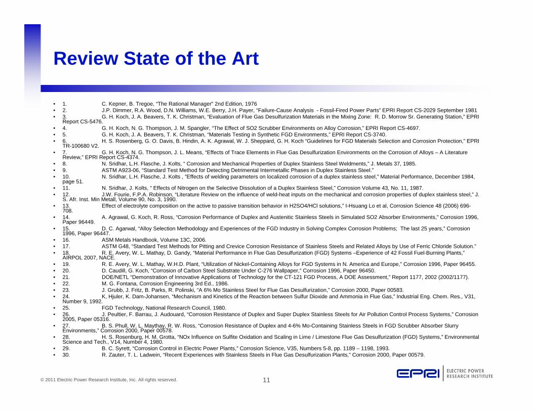
• 1. C. Kepner, B. Tregoe, “The Rational Manager” 2nd Edition, 1976• 2. J.P. Dimmer, R.A. Wood, D.N. Williams, W.E. Berry, J.H. Payer, “Failure-Cause Analysis - Fossil-Fired Power Parts” EPRI Report CS-2029 September 1981• 3. G. H. Koch, J. A. Beavers, T. K. Christman, “Evaluation of Flue Gas Desulfurization Materials in the Mixing Zone: R. D. Morrow Sr. Generating Station,” EPRI
Report CS-5476.• 4. G. H. Koch, N. G. Thompson, J. M. Spangler, “The Effect of SO2 Scrubber Environments on Alloy Corrosion,” EPRI Report CS-4697.• 5. G. H. Koch, J. A. Beavers, T. K. Christman, “Materials Testing in Synthetic FGD Environments,” EPRI Report CS-3740.• 6. H. S. Rosenberg, G. O. Davis, B. Hindin, A. K. Agrawal, W. J. Sheppard, G. H. Koch “Guidelines for FGD Materials Selection and Corrosion Protection,” EPRI
TR-100680 V2.• 7. G. H. Koch, N. G. Thompson, J. L. Means, “Effects of Trace Elements in Flue Gas Desulfurization Environments on the Corrosion of Alloys – A Literature
Review,” EPRI Report CS-4374.• 8. N. Sridhar, L.H. Flasche, J. Kolts, “ Corrosion and Mechanical Properties of Duplex Stainless Steel Weldments,” J. Metals 37, 1985.• 9. ASTM A923-06, “Standard Test Method for Detecting Detrimental Intermetallic Phases in Duplex Stainless Steel.”• 10. N. Sridhar, L.H. Flasche, J. Kolts , ”Effects of welding parameters on localized corrosion of a duplex stainless steel,” Material Performance, December 1984,
page 51.• 11. N. Sridhar, J. Kolts, “ Effects of Nitrogen on the Selective Dissolution of a Duplex Stainless Steel,” Corrosion Volume 43, No. 11, 1987.• 12. J.W. Fourie, F.P.A. Robinson, “Literature Review on the influence of weld-heat inputs on the mechanical and corrosion properties of duplex stainless steel,” J.
S. Afr. Inst. Min Metall, Volume 90, No. 3, 1990.• 13. Effect of electrolyte composition on the active to passive transition behavior in H2SO4/HCl solutions,” I-Hsuang Lo et al, Corrosion Science 48 (2006) 696-
708.• 14. A. Agrawal, G. Koch, R. Ross, “Corrosion Performance of Duplex and Austenitic Stainless Steels in Simulated SO2 Absorber Environments,” Corrosion 1996,
Paper 96449.• 15. D. C. Agarwal, “Alloy Selection Methodology and Experiences of the FGD Industry in Solving Complex Corrosion Problems; The last 25 years,” Corrosion
1996, Paper 96447.• 16. ASM Metals Handbook, Volume 13C, 2006.• 17. ASTM G48, “Standard Test Methods for Pitting and Crevice Corrosion Resistance of Stainless Steels and Related Alloys by Use of Ferric Chloride Solution.”• 18. R. E. Avery, W. L. Mathay, D. Gandy, “Material Performance in Flue Gas Desulfurization (FGD) Systems –Experience of 42 Fossil Fuel-Burning Plants,”
AIRPOL 2007, NACE.• 19. R. E. Avery, W. L. Mathay, W.H.D. Plant, “Utilization of Nickel-Containing Alloys for FGD Systems in N. America and Europe,” Corrosion 1996, Paper 96455.• 20. D. Caudill, G. Koch, “Corrosion of Carbon Steel Substrate Under C-276 Wallpaper,” Corrosion 1996, Paper 96450.• 21. DOE/NETL “Demonstration of Innovative Applications of Technology for the CT-121 FGD Process, A DOE Assessment,” Report 1177, 2002 (2002/1177).• 22. M. G. Fontana, Corrosion Engineering 3rd Ed., 1986.• 23. J. Grubb, J. Fritz, B. Parks, R. Polinski, “A 6% Mo Stainless Steel for Flue Gas Desulfurization,” Corrosion 2000, Paper 00583.• 24. K, Hjuler, K. Dam-Johansen, “Mechanism and Kinetics of the Reaction between Sulfur Dioxide and Ammonia in Flue Gas,” Industrial Eng. Chem. Res., V31,
Number 9, 1992.• 25. FGD Technology, National Research Council, 1980.• 26. J. Peultier, F. Barrau, J. Audouard, “Corrosion Resistance of Duplex and Super Duplex Stainless Steels for Air Pollution Control Process Systems,” Corrosion
2005, Paper 05316.• 27. B. S. Phull, W. L. Maythay, R. W. Ross, “Corrosion Resistance of Duplex and 4-6% Mo-Containing Stainless Steels in FGD Scrubber Absorber Slurry
Environments,” Corrosion 2000, Paper 00578.• 28. H. S. Rosenburg, H. M. Grotta, “NOx Influence on Sulfite Oxidation and Scaling in Lime / Limestone Flue Gas Desulfurization (FGD) Systems,” Environmental
Science and Tech., V14, Number 4, 1980.• 29. B. C. Syrett, “Corrosion Control in Electric Power Plants,” Corrosion Science, V35, Numbers 5-8, pp. 1189 – 1198, 1993.• 30. R. Zauter, T. L. Ladwein, “Recent Experiences with Stainless Steels in Flue Gas Desulfurization Plants,” Corrosion 2000, Paper 00579.
Review State of the Art

12© 2011 Electric Power Research Institute, Inc. All rights reserved.
Structure of RCA
• Show RCA slides

13© 2011 Electric Power Research Institute, Inc. All rights reserved.
RCA Outcome
• The RCA 2011 schedule is:– Literature review by the end of Q1 – Draft report by the end of Q2– Member comments incorporated by end of Q3– Final report and wrap up at the end of 2011
• The goal is to leverage experience to generate a complete, rapid response– Knowledge gaps need to be addressed quickly

14© 2011 Electric Power Research Institute, Inc. All rights reserved.
Together…Shaping the Future of Electricity

15© 2011 Electric Power Research Institute, Inc. All rights reserved.
Supplemental slides
• Modeling absorbers materials

16© 2011 Electric Power Research Institute, Inc. All rights reserved.
Supplemental slides

17© 2011 Electric Power Research Institute, Inc. All rights reserved.
Supplemental slides

Nondestructive Evaluation Possibilities
Stan M. Walker Sr. Project ManagerCorrosion in Wet Flue Gas Desulfurization (FGD) Systems January 27-28, 2011
2© 2011 Electric Power Research Institute, Inc. All rights reserved.
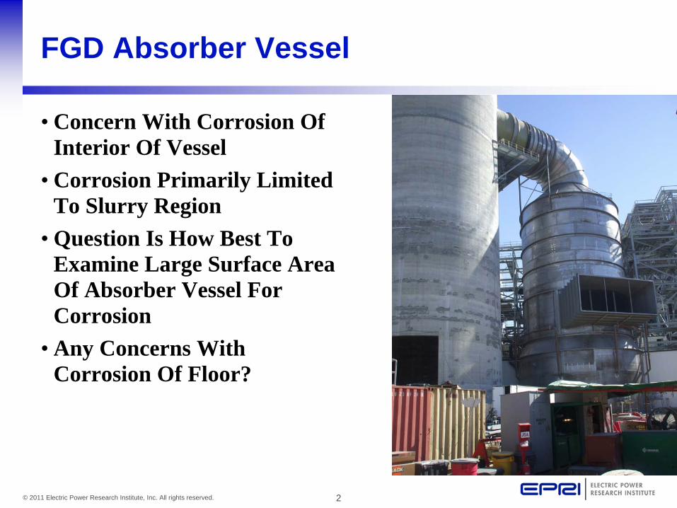
FGD Absorber Vessel
• Concern With Corrosion Of Interior Of Vessel
• Corrosion Primarily Limited To Slurry Region
• Question Is How Best To Examine Large Surface Area Of Absorber Vessel For Corrosion
• Any Concerns With Corrosion Of Floor?

3© 2011 Electric Power Research Institute, Inc. All rights reserved.
Interior Of Absorber Vessel
• Access To Interior Is Good After Cleaning
• Consider Real-Time Digital Radiography– Detector Inside– Source Outside– Synchronous Motion For Each
• Consider Ultrasonic Guided Waves

4© 2011 Electric Power Research Institute, Inc. All rights reserved.
Real-Time Radiography
• Detector Could Be Suspended From Above Similar To Boiler Waterwall System
• X-Ray Source Place On Motion Device On Outside
• Synchronous Motion Allows Scanning At ~5 Feet (1.5 Meter) Per Minute
5© 2011 Electric Power Research Institute, Inc. All rights reserved.
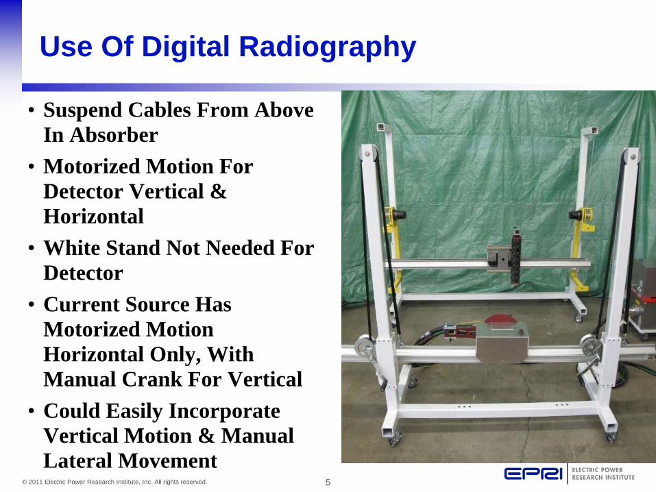
Use Of Digital Radiography
• Suspend Cables From Above In Absorber
• Motorized Motion For Detector Vertical & Horizontal
• White Stand Not Needed For Detector
• Current Source Has Motorized Motion Horizontal Only, With Manual Crank For Vertical
• Could Easily Incorporate Vertical Motion & Manual Lateral Movement

6© 2011 Electric Power Research Institute, Inc. All rights reserved.
Ultrasonic Guided Waves
• Place Guided Wave Sensors On Outside Of Vessel
• No Cleaning• Guided Waves Directed
Vertically Or Circumferentially• Detection Of Damage Exceeding
2-5% Cross Section• Would Also Detect Various
Geometrical Anomalies– Welds, Attachments, Openings
• Might Be Feasible To Use Monitoring Mode– Sensors In Place & Measure
Changes
7© 2011 Electric Power Research Institute, Inc. All rights reserved.
Potential Unknowns
• Radiography– Personnel Exclusion Zone Size– Mechanization Mods– May Only Detect Abrupt Changes
• Guided Waves– Affects Of Duplex Steel– Attaching Sensors– Determination Of Non-Damage Signals
• After Baseline Established, Very Easy– May Be Possible To Mount Sensors Vertically At 1 Location &
Examine 360° - 180° Each Direction