agilent 11713b/c attenuator/switch drivers · viking connector to 10-pin dip connector viking...
TRANSCRIPT

Agilent 11713B/C
Attenuator/Switch Drivers
Confi guration Guide
This confi guration guide will assist you through the process of
confi guring a switching system using the Agilent 11713B/C attenuator/switch drivers.

2
Key Features
The 11713B attenuator/switch driver is a GPIB compatible instrument that concurrently drives up to two four-section
programmable step attenuators and two microwave coaxial switches, or up to 10 SPDT switches2. The 11713B is fully
backward compatible with the 11713A in terms of functionality and fi t. Connectivity using USB and LAN are optional.
The 11713C attenuator/switch driver is a GPIB/USB/LAN compatible instrument that concurrently drives up to four
programmable step attenuators and four microwave coaxial switches, or up to 20 SPDT switches2. The 11713C comes
with tri-voltage selection of 5V, 15V and 24V and also permits user-defi ned voltage supply capability.
• Programming via GPIB/USB can be accomplished in simple one-line statements.
• Control the attenuator/switch drivers through LAN using a web-based interface.
• An integrated LCD display eases menu selection and instrument confi guration.
• Inclusion of solenoid arc suppression diodes with three pre-defi ned common terminal supplies allow the instrument
to be used with wide variety of attenuators and switches.
Key features 11713B 11713C
Manually-controlled using front panel push buttons Yes Yes
Automatically-control through:
• GPIB
• USB
• LAN
Yes
Optional
Optional
Yes
Yes
Yes
Integrated LCD display Yes Yes
Self-contained power supply with current limiting Yes Yes
Common terminal supplies of
• +5 Vdc
• +15 Vdc
• +24 Vdc
• User-defi ned
No
No
Yes
No
Yes
Yes
Yes
Yes
TTL control No Yes
Note 1: 11713B/C attenuator/switch drivers output continuous current and do not support pulse drive. Please ensure your switching devices can
withstand continuous current or have a built-in current interrupt feature.
Note 2: The amount of switches and attenuators that can be driven will depend on the type of switch confi guration and attenuator section confi guration.
The 11713C can drive twice as many devices as the 11713B; however, the total load current that can be consumed is still 1.7A.

3
Drive power supply specifi cations
Specifi cations below describe warranted performance over the temperature range of 0 to 50 ºC after one hour of continuous operation, unless
otherwise noted.
Voltage
+24 ± 8% Vdc
+5 ± 5% Vdc
+15 ± 12% Vdc
Current
1.7 A maximum continuous current
Contact pairs 1 through 8, 9 and 0, maximum current of 0.7 A per contact
Supplemental characteristics
Supplemental characteristics are intended to provide useful information and are typical but non-warranted performance parameters.
Power100 or 240 Vac, autommatic selection, 50/60 Hz
100 VA maximum
Response time 100 µs maximum for contact pairs 1 through 8
20 ms maximum for contact pairs 9 and 0
Driver life 2,000,000 switchings at 0.7 A for contact pairs 9 and 0
Maximum load inductance 500 mH
Maximum load capacitance < 0.01 µF for contact pairs 9 and 0
Physical specifi cations
Net weight 3.2 kg (7.1 lbs)
Dimensions (H x W x D) with handle and rubber
bumper
130 mm x 250 mm x 462 mm (5.1 inches x 9.8 inches x 18.2 inches)
Dimensions (H x W x D) without handle and
rubber bumper
88 mm x 212 mm x 348 mm (3.5 inches x 8.5 inches x 13.7 inches)
Specifi cations

4
Product Confi gurations
The 11713B/C attenuator/switch drivers can be confi gured easily. The connection between the driver and switching
devices is intuitive and direct. Simply select the appropriate interface cable and you can make point-to-point connection
from the driver to the attenuator(s) and/or switch(es). Details such as pin numbers and wires color are provided in the
tables found in Confi guration Information for Switches and Confi guration Information for Attenuators sections.
Note 1: The maximum quantity orderable for each cable option is 9.
11713BConnectivity options
Option STD Standard confi guration, full backward compatibility to 11713A
Option LXI LXI Class-C confi guration, additional USB/LAN connectivity, full backward compatibility to 11713A
Cable options
Option 001
Option 101
Option 201
Option 301
Option 401
Option 501
Option 601
Option 701
Option 801
Part number
11764-60004
8120-2703
5061-0969
11761-60001
11713-60042
11713-60043
11713-60044
5064-7848
11713-60047
Viking connector to 10-pin DIP connector
Viking connector to viking connector
Viking connector to 12-pin conductor cable, bare wire
Viking connector to 4 ribbon cables
Dual-viking connector to 16-pin DIP connector
Viking connector to (4) 9-pin Dsub connectors
Viking connector to 16-pin DIP connector
Viking connector to 14-pin DIP connector
Viking connector to (4) 10-pin DIP connectors
Rack mount kit
options (optional)
Option 908
Option 909
Part number
5063-9240
5061-9496
& 5063-9212
Rack mount kit for one instrument
Rack mount kit for two instruments
11713CCable options
Option 001
Option 101
Option 201
Option 301
Option 401
Option 501
Option 601
Option 701
Option 801
Part number
11764-60004
8120-2703
5061-0969
11761-60001
11713-60042
11713-60043
11713-60044
5064-7848
11713-60047
Viking connector to 10-pin DIP connector
Viking connector to viking connector
Viking connector to 12-pin conductor cable, bare wire
Viking connector to 4 ribbon cables
Dual-viking connector to 16-pin DIP connector
Viking connector to (4) 9-pin Dsub connectors
Viking connector to 16-pin DIP connector
Viking connector to 14-pin DIP connector
Viking connector to (4) 10-pin DIP connectors
Rack mount kit
options (optional)
Option 908
Option 909
Part number
5063-9240
5061-9496
& 5063-9212
Rack mount kit for one instrument
Rack mount kit for two instruments
Cable and rack mount kit can be ordered separately with the part numbers below.11713B-001/11713C-001 Viking connector to 10-pin DIP connector
11713B-101/11713C-101 Viking connector to viking connector
11713B-201/11713C-201 Viking connector to 12-pin conductor cable, bare wire
11713B-301/11713C-301 Viking connector to 4 ribbon cables
11713B-401/11713C-401 Dual-viking connector to 16-pin DIP connector
11713B-501/11713C-501 Viking connector to (4) 9-pin Dsub connectors
11713B-601/11713C-601 Viking connector to 16-pin DIP connector
11713B-701/11713C-701 Viking connector to 14-pin DIP connector
11713B-801/11713C-801 Viking connector to (4) 10-pin DIP connectors
11713B-908/11713C-908 Rack mount kit for one instrument
11713B-909/11713C-909 Rack mount kit for two instruments

5
Five Simple Steps to Confi gure your Switching System
1.. Determine the switching device’s model and option (DC connector).
Example Model: 87104A (SP4T switch)
Option: 100 (solder terminal)
2.. Determine the attenuator/switch driver’s model and option (interface cable).
Example Model: 11713B
Option: 201 (Viking connector to 12-pin conductor cable, bare wire)
3. Use the selection guide, Table A (page 11) for switches and Table B (page 12) for attenuators,
to determine which confi guration table to use for further reference.
Example Selection guide: Table A (for switches)
Confi guration table: Table F-1
4.. Confi gure your switching system using Table F-1 (page 16) as a reference.
5.. Operate your system.

Switch
familySwitch model number Switch option
11713B/C
Option 001 Option 101 Option 201 Option 301 Option 401 Option 501 Option 601 Option 701 Option 801
Bypass 8763A, 8763B, 8763C011/015/024 Table D-2
T15/T24 Table D-5
8764A, 8764B, 8764C011/015/024 Table D-3
T15/T24 Table D-6
N1811TL²
202/403 Table O-3201/403 Table O-4
202/401/403 Table O-7201/401/403 Table O-8
N1812UL²
202/403 Table O-1201/403 Table O-2
202/401/403 Table O-5201/401/403 Table O-6
SPDT 8761A, 8761B 1 No option Table C-18762A, 8762B, 8762C,
8762F
011/015/024 Table D-1T15/T24 Table D-4
8765A, 8765B, 8765C,
8765D, 8765F³
305/310/315/324 Table E-1
005/010/015/024 Table E-2
N1810UL²
202/403 Table O-1201/403 Table O-2
202/401/403 Table O-5201/401/403 Table O-6
N1810TL²
202/403 Table O-3201/403 Table O-4
202/401/403 Table O-7201/401/403 Table O-8
SP3T8766K
016 Table J-1
060 Table J-2
SP4T 87104A, 87104B,
87104C, 87104D
100 Table F-1
161 Table F-2
87204A, 87204B,
87204C
100 Table G-1
161 Table G-2
L7104A, L7104B,
L7104C
100 Table F-1
161 Table F-2
L7204A, L7204B,
L7204C
100 Table F-1
161 Table F-2
8767K016 Table J-1
060 Table J-2
8767M No option Table L
SP5T8768K
016 Table J-1
060 Table J-2
8768M No option Table L
SP6T 87106A, 87106B,
87106C, 87106D
100 Table H-1
161 Table H-2
87206A, 87206B,
87206C
100 Table I-1
161 Table I-2
L7106A, L7106B,
L7106C
100 Table H-1
161 Table H-2
L7206A, L7206B,
L7206C
100 Table H-1
161 Table H-2
8769K 060 Table K
8769M No option Table M
Matrix87406B
100 Table H-1
161 Table H-2
87606B100 Table I-1
161 Table I-2
Transfer 87222C, 87222D,
87222E
100 Table N-1
161 Table N-2
L7222C100 Table N-1
161 Table N-2
1. Refer to Table C-2 if a cable with banana jacks is used to make a connection between 8761A/B and 11713B/C.
2. N1810UL/TL, N1811TL and N1812UL cannot withstand continuous current. Option 403 (current interrupt) is required
to protect the switches from damage due to overheating.
3. 8765A/B/C/D/F require continuous current to latch. The number of switches for connection depends on option selection.
Table A: Selection guide for switches
6
7
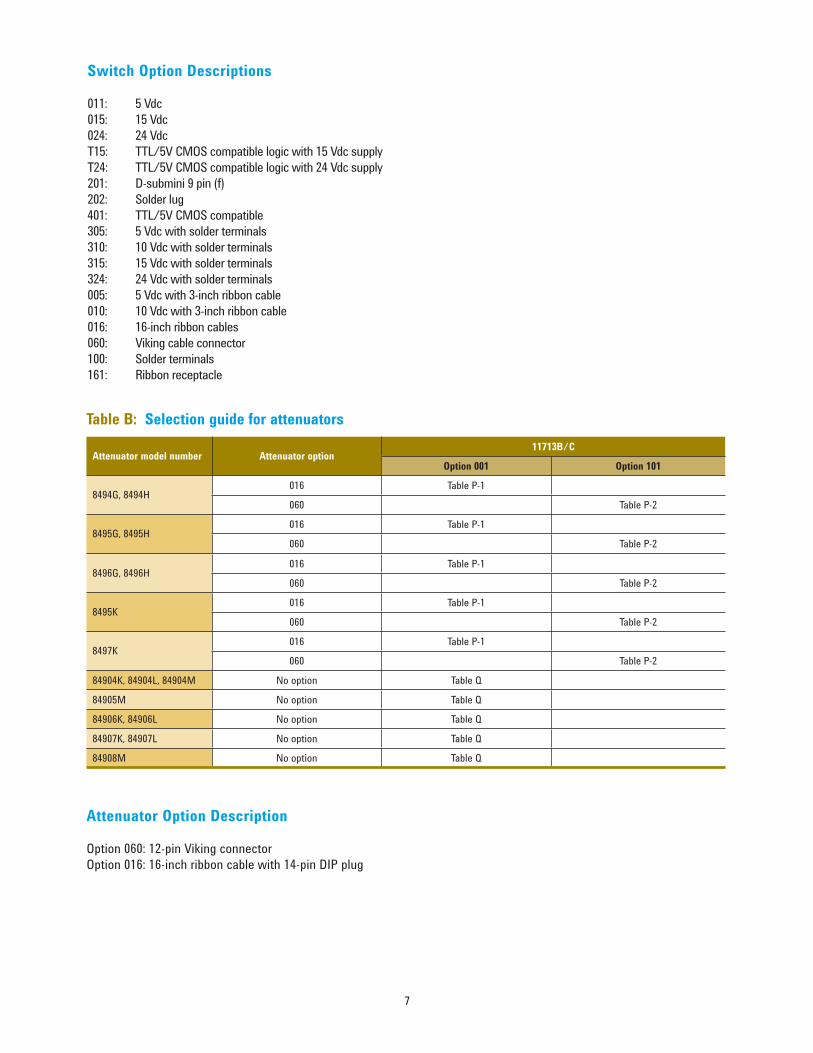
Attenuator model number Attenuator option11713B/C
Option 001 Option 101
8494G, 8494H016 Table P-1
060 Table P-2
8495G, 8495H016 Table P-1
060 Table P-2
8496G, 8496H016 Table P-1
060 Table P-2
8495K016 Table P-1
060 Table P-2
8497K016 Table P-1
060 Table P-2
84904K, 84904L, 84904M No option Table Q
84905M No option Table Q
84906K, 84906L No option Table Q
84907K, 84907L No option Table Q
84908M No option Table Q
Attenuator Option Description
Option 060: 12-pin Viking connector
Option 016: 16-inch ribbon cable with 14-pin DIP plug
Table B: Selection guide for attenuators
Switch Option Descriptions
011: 5 Vdc
015: 15 Vdc
024: 24 Vdc
T15: TTL/5V CMOS compatible logic with 15 Vdc supply
T24: TTL/5V CMOS compatible logic with 24 Vdc supply
201: D-submini 9 pin (f)
202: Solder lug
401: TTL/5V CMOS compatible
305: 5 Vdc with solder terminals
310: 10 Vdc with solder terminals
315: 15 Vdc with solder terminals
324: 24 Vdc with solder terminals
005: 5 Vdc with 3-inch ribbon cable
010: 10 Vdc with 3-inch ribbon cable
016: 16-inch ribbon cables
060: Viking cable connector
100: Solder terminals
161: Ribbon receptacle

8
From 11713B/C (Option 201)To 8761A/B
Front panel pushbutton Interface cable
Switches LEDViking connector
pin numberBare wire color
Solder terminal
numberRF path Device under test (DUT)
9
OFF Cable 1-3 Gray <+>2 to C closed
DUT 1Cable 1-4 White/Red <–>
ON Cable 1-3 Gray <+>1 to C closed
Cable 1-4 White/Red <–>
0
OFF Cable 2-3 Gray <+>2 to C closed
DUT 2Cable 2-4 White/Red <–>
ON Cable 2-3 Gray <+>1 to C closed
Cable 2-4 White/Red <–>
From 11713B/C (any option)To 8761A/B
Front panel pushbutton Banana jack (rear panel)
Switches LED Pin number VoltageSolder terminal
numberRF path Device under test (DUT)
9
OFFS9-A +V <+>
2 to C closed
DUT 1S9-B 0 <–>
ONS9-A 0 <+>
1 to C closedS9-B +V <–>
0
OFFS0-A +V <+>
2 to C closed
DUT 2S0-B 0 <–>
ONS0-A 0 <+>
1 to C closedS0-B +V <–>
Table C-1: Confi guration of 11713B/C (Option 201) to 8761A/B SPDT switches
Table C-2: Confi guration of 11713B/C (any option) to 8761A/B SPDT switches
Note 1: Each table below illustrates the confi guration of two switches to the 11713B/C.
Note 2: For 8761A, V = 15V.
Note 3: For 8761B, V = 24V.
Note 4: 2,000,000 switching cycles at 0.7 A for contact pairs 9 and 0. For more details, please refer to the “Supplemental characteristics” table on page 3.
Confi guration Information for Switches

9
From 11713B/C (Option 201)To 8762A/B/C/F (Option 005/011/024)
Front panel pushbutton Interface cable
Attenuator X LEDViking connector
pin numberBare wire color
Solder terminal
numberRF path
Device under test (DUT)
– – 1 (VCC) Red C – VCC for all 5 DUTs
1OFF 5 Violet 1 1 to C closed, 2 terminated
DUT 1ON 6 Yellow 2 2 to C closed, 1 terminated
2OFF 7 Black 1 1 to C closed, 2 terminated
DUT 2ON 8 Green 2 2 to C closed, 1 terminated
3OFF 9 Orange 1 1 to C closed, 2 terminated
DUT 3ON 10 Blue 2 2 to C closed, 1 terminated
4OFF 11 Brown 1 1 to C closed, 2 terminated
DUT 4ON 12 White 2 2 to C closed, 1 terminated
9OFF 4 Gray 1 1 to C closed, 2 terminated
DUT 5ON 3 White/Red 2 2 to C closed, 1 terminated
Table D-2: Confi guration of 11713B/C (Option 201) to 8763A/B/C bypass switches (Option 005/011/024)
From 11713B/C (Option 201)To 8763A/B/C (Option 005/011/024)
Front panel pushbutton Interface cable
Attenuator X LEDViking connector
pin numberBare wire color
Solder terminal
numberRF path
Device under test (DUT)
– – 1 (VCC) Red C – VCC for all 5 DUTs
1OFF 5 Violet 1 1 to 2 closed, 3 to 4 closed
DUT 1ON 6 Yellow 2 1 terminated, 2 to 3 closed, 4 open
2OFF 7 Black 1 1 to 2 closed, 3 to 4 closed
DUT 2ON 8 Green 2 1 terminated, 2 to 3 closed, 4 open
3OFF 9 Orange 1 1 to 2 closed, 3 to 4 closed
DUT 3ON 10 Blue 2 1 terminated, 2 to 3 closed, 4 open
4OFF 11 Brown 1 1 to 2 closed, 3 to 4 closed
DUT 4ON 12 White 2 1 terminated, 2 to 3 closed, 4 open
9OFF 4 Gray 1 1 to 2 closed, 3 to 4 closed
DUT 5ON 3 White/Red 2 1 terminated, 2 to 3 closed, 4 open
Table D-3: Confi guration of 11713B/C (Option 201) to 8764A/B/C bypass switches (Option 005/011/024)
From 11713B/C (Option 201)To 8764A/B/C (Option 005/011/024)
Front panel pushbutton Interface cable
Attenuator X LEDViking connector
pin numberBare wire color
Solder terminal
numberRF path
Device under test (DUT)
– – 1 (VCC) Red C – VCC for all 5 DUTs
1OFF 5 Violet 1 1 open, 2 to 3 closed, 4 to 5 closed
DUT 1ON 6 Yellow 2 1 to 2 closed, 3 to 4 closed, 5 open
2OFF 7 Black 1 1 open, 2 to 3 closed, 4 to 5 closed
DUT 2ON 8 Green 2 1 to 2 closed, 3 to 4 closed, 5 open
3OFF 9 Orange 1 1 open, 2 to 3 closed, 4 to 5 closed
DUT 3ON 10 Blue 2 1 to 2 closed, 3 to 4 closed, 5 open
4OFF 11 Brown 1 1 open, 2 to 3 closed, 4 to 5 closed
DUT 4ON 12 White 2 1 to 2 closed, 3 to 4 closed, 5 open
9OFF 4 Gray 1 1 open, 2 to 3 closed, 4 to 5 closed
DUT 5ON 3 White/Red 2 1 to 2 closed, 3 to 4 closed, 5 open
Table D-1: Confi guration of 11713B/C (Option 201) to 8762A/B/C/F SPDT switches (Option 005/011/024)
Note 1: Each table below illustrates the confi guration of fi ve switches to the 11713B/C.
Note 2: Five additional switches can be driven by Attenuator Y (front panel pushbuttons 5, 6, 7, 8 & 0) using the same confi guration as Attenuator X.
Note 3: 2,000,000 switching cycles at 0.7 A for contact pairs 9 and 0. For more details, please refer to the “Supplemental characteristics” table on page 3.

10
From 11713B/C (Option 201)To 8762A/B/C/F (Option T15/T24)
Front Panel Pushbutton Interface Cable
Attenuator X LEDViking Connector
Pin NumberBare Wire Color
Solder Terminal
NumberRF Path
Device Under Test
(DUT)
– – 1 (VCC) Red C – VCC for all 5 DUTs
– – 2 (GND) White/Brown 2 – GND for all 5 DUTs
1OFF
5 Violet 11 to C closed, 2 terminated
DUT 1ON 2 to C closed, 1 terminated
2OFF
7 Black 11 to C closed, 2 terminated
DUT 2ON 2 to C closed, 1 terminated
3OFF
9 Orange 11 to C closed, 2 terminated
DUT 3ON 2 to C closed, 1 terminated
4OFF
11 Brown 11 to C closed, 2 terminated
DUT 4ON 2 to C closed, 1 terminated
9OFF
4 Gray 11 to C closed, 2 terminated
DUT 5ON 2 to C closed, 1 terminated
Table D-5: Confi guration of 11713B/C (Option 201) to 8763A/B/C bypass switches (Option T15/T24)
From 11713B/C (Option 201)To 8763A/B/C (Option T15/T24)
Front Panel Pushbutton Interface Cable
Attenuator X LEDViking Connector
Pin NumberBare Wire Color
Solder Terminal
NumberRF Path
Device Under Test
(DUT)
– – 1 (VCC) Red C – VCC for all 5 DUTs
– – 2 (GND) White/Brown 2 – GND for all 5 DUTs
1OFF
5 Violet 11 to 2 closed, 3 to 4 closed
DUT 1ON 1 terminated, 2 to 3 closed, 4 open
2OFF
7 Black 11 to 2 closed, 3 to 4 closed
DUT 2ON 1 terminated, 2 to 3 closed, 4 open
3OFF
9 Orange 11 to 2 closed, 3 to 4 closed
DUT 3ON 1 terminated, 2 to 3 closed, 4 open
4OFF
11 Brown 11 to 2 closed, 3 to 4 closed
DUT 4ON 1 terminated, 2 to 3 closed, 4 open
9OFF
4 Gray 11 to 2 closed, 3 to 4 closed
DUT 5ON 1 terminated, 2 to 3 closed, 4 open
Table D-6: Confi guration of 11713B/C (Option 201) to 8764A/B/C bypass switches (Option T15/T24)
From 11713B/C (Option 201)To 8764A/B/C (Option T15/T24)
Front Panel Pushbutton Interface Cable
Attenuator X LEDViking Connector
Pin NumberBare Wire Color
Solder Terminal
NumberRF Path
Device Under Test
(DUT)
– – 1 (VCC) Red C – VCC for all 5 DUTs
– – 2 (GND) White/Brown 2 – GND for all 5 DUTs
1OFF
5 Violet 11 open, 2 to 3 closed, 4 to 5 closed
DUT 1ON 1 to 2 closed, 3 to 4 closed, 5 open
2OFF
7 Black 11 open, 2 to 3 closed, 4 to 5 closed
DUT 2ON 1 to 2 closed, 3 to 4 closed, 5 open
3OFF
9 Orange 11 open, 2 to 3 closed, 4 to 5 closed
DUT 3ON 1 to 2 closed, 3 to 4 closed, 5 open
4OFF
11 Brown 11 open, 2 to 3 closed, 4 to 5 closed
DUT 4ON 1 to 2 closed, 3 to 4 closed, 5 open
9OFF
4 Gray 11 open, 2 to 3 closed, 4 to 5 closed
DUT 5ON 1 to 2 closed, 3 to 4 closed, 5 open
Table D-4: Confi guration of 11713B/C (Option 201) to 8762A/B/C/F SPDT switches (Option T15/T24)
Note 1: Each table below illustrates the confi guration of fi ve switches to the 11713B/C.
Note 2: Five additional switches can be driven by Attenuator Y (front panel pushbuttons 5, 6, 7, 8 & 0) using the same confi guration as Attenuator X.
Note 3: 2,000,000 switching cycles at 0.7 A for contact pairs 9 and 0. For more details, please refer to the “Supplemental characteristics” table on page 3.

11
Table E-1: Confi guration of 11713B/C (Option 201)
to 8765A/B/C/D/F SPDT switches (Options 3xx)
From 11713B/C (Option 201)To 8765A/B/C/D/F (Option 305/310/315/324)
Front Panel Pushbutton Interface Cable
Attenuator X LEDViking connector
pin numberBare wire color
Solder terminal
numberRF path Device under test (DUT)
- - 1 (VCC) Red 2 and 3 - VCC for all 5 DUTs
1OFF 5 Violet 1 2 to C closed, 1 open
DUT 1ON 6 Yellow 4 1 to C closed, 2 open
2OFF 7 Black 1 2 to C closed, 1 open
DUT 2ON 8 Green 4 1 to C closed, 2 open
3OFF 9 Orange 1 2 to C closed, 1 open
DUT 3ON 10 Blue 4 1 to C closed, 2 open
4OFF 11 Brown 1 2 to C closed, 1 open
DUT 4ON 12 White 4 1 to C closed, 2 open
9OFF 4 Gray 1 2 to C closed, 1 open
DUT 5ON 3 White/Red 4 1 to C closed, 2 open
Table E-2: Confi guration of 11713B/C (Option 301)
to 8765A/B/C/D/F SPDT switches (Options 0xx)
From 11713B/C (Option 301)To 8765A/B/C/D/F (Option 005/010/015/024)
Front panel pushbutton Interface cable
Attenuator X LED
Viking connector
pin number/
banana jack
(rear panel)
5-pin receptacle
pin number
Ribbon cable
connector pin numberRF path Device under test (DUT)
– – 1 (VCC)/VDC COM 3 and 4 3 and 4 – VCC for all 5 DUTs
1OFF 5 1 1 2 to C closed, 1 open
DUT 1ON 6 5 5 1 to C closed, 2 open
2OFF 7 1 1 2 to C closed, 1 open
DUT 2ON 8 5 5 1 to C closed, 2 open
3OFF 9 1 1 2 to C closed, 1 open
DUT 3ON 10 5 5 1 to C closed, 2 open
4OFF 11 1 1 2 to C closed, 1 open
DUT 4ON 12 5 5 1 to C closed, 2 open
9OFF S9-A — 1 2 to C closed, 1 open
DUT 5ON S9-B — 5 1 to C closed, 2 open
Note 1: Each table below illustrates the confi guration of fi ve switches to the 11713B/C.
Note 2: Requires continuous current to latch. The number of switches available for connection depends on option selection.
Note 3: Five switches can be driven by Attenuator Y (front panel pushbuttons 5, 6, 7, 8 & 0) using the same confi guration as Attenuator X. Note 4: 2,000,000 switching cycles at 0.7 A for contact pairs 9 and 0. For more details, please refer to the “Supplemental characteristics” table on page

12
Table F-1: Confi guration of 11713B/C (Option 201)
to 87104A/B/C/D, L7104A/B/C & L7204A/B/C SP4T switches (Option 100)
From 11713B/C (Option 201)To 87104A/B/C/D, L7104A/B/C & L7204A/B/C (Option 100)
Front panel pushbutton Interface cable
Attenuator X LEDViking connector
pin numberBare wire color Solder terminal number RF path
– – 1 (VCC) Red 1 –
– – 2 (GND) White/Brown 15 –
1 OFF 5 Violet 5 2 to C closed
2 OFF 7 Black 7 3 to C closed
3 OFF 9 Orange 11 5 to C closed
4 OFF 11 Brown 13 6 to C closed
From 11713B/C (Option 601)To 87104A/B/C/D, L7104A/B/C & L7204A/B/C (Option 161)
Front panel pushbutton Interface cable
Attenuator X LEDViking connector
pin number
16-pin DIP
pin numberRF path
– – 1 (VCC) 1 –
– – 2 (GND) 15 –
1 OFF 5 5 2 to C closed
2 OFF 7 7 3 to C closed
3 OFF 9 11 5 to C closed
4 OFF 11 13 6 to C closed
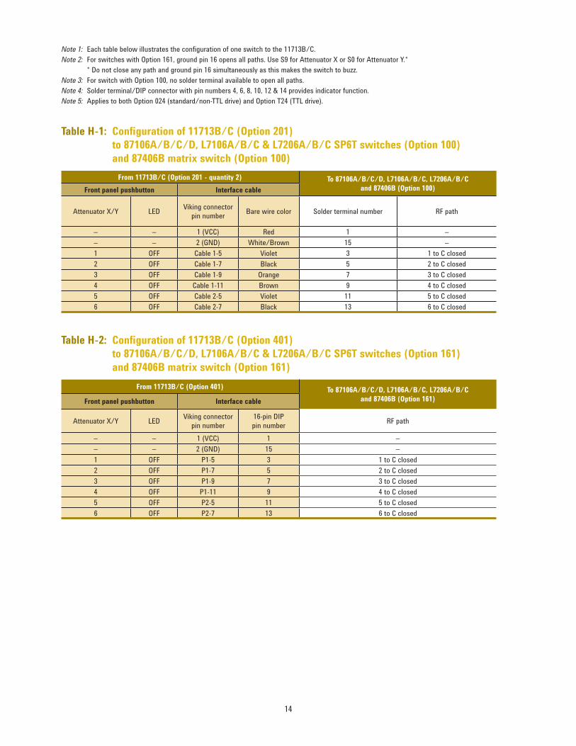
Note 1: Each table below illustrates the confi guration of one switch to the 11713B/C.
Note 2: For switches with Option 161, ground pin 16 opens all paths. Use S9 for Attenuator X or S0 for Attenuator Y.*
* Do not close any path and ground pin 16 simultaneously as this makes the switch buzz.
Note 3: For switches with Option 100, there are no solder terminals available to open all paths.
Note 4: Solder terminal/DIP connector with pin numbers 6, 8, 12 & 14 provides indicator function.
Note 5: Applies to both Option 024 (standard/non-TTL drive) and Option T24 (TTL drive).
Note 6: One additional switch can be driven by Attenuator Y (front panel pushbuttons 5, 6, 7 & 8) using the same confi guration as Attenuator X.
Table F-2: Confi guration of 11713B/C (Option 601)
to 87104A/B/C/D, L7104A/B/C & L7204A/B/C SP4T switches (Option 161)

13
From 11713B/C (Option 201)To 87204A/B/C (Option 100)
Front panel pushbutton Interface cable
Attenuator X LEDViking connector
pin numberBare wire color Solder terminal number RF path
– – 1 (VCC) Red 1 –
– – 2 (GND) White/Brown 15 –
1OFF 5 Violet 5 2 to C closed
ON 6 Yellow 6 2 to C opened
2OFF 7 Black 7 3 to C closed
ON 8 Green 8 3 to C opened
3OFF 9 Orange 11 5 to C closed
ON 10 Blue 12 5 to C opened
4OFF 11 Brown 13 6 to C closed
ON 12 White 14 6 to C opened
From 11713B/C (Option 601)To 87204A/B/C (Option 161)
Front panel pushbutton Interface cable
Attenuator X LEDViking connector
pin number
16-pin DIP
pin numberRF path
– – 1 (VCC) 1 –
– – 2 (GND) 15 –
1OFF 5 5 2 to C closed
ON 6 6 2 to C opened
2OFF 7 7 3 to C closed
ON 8 8 3 to C opened
3OFF 9 11 5 to C closed
ON 10 12 5 to C opened
4OFF 11 13 6 to C closed
ON 12 14 6 to C opened
Note 1: Each table below illustrates the confi guration of one switch to the 11713B/C.
Note 2: For switches with Option 161, ground pin 16 opens all paths. Use S9 for Attenuator X or S0 for Attenuator Y.*
* Do not close any path and ground pin 16 simultaneously as this makes the switch to buzz.
Note 3: For switch with Option 100, no solder terminal available to open all paths.
Note 4: Applies to both Option 024 (standard/non-TTL drive) and Option T24 (TTL drive).
Note 5: One additional switch can be driven by Attenuator Y (front panel pushbuttons 5, 6, 7 & 8) using the same confi guration as Attenuator X.
Table G-1: Confi guration of 11713B/C (Option 201) to 87204A/B/C SP4T switches (Option 100)
Table G-2: Confi guration of 11713B/C (Option 601) to 87204A/B/C SP4T switches (Option 161)
14
From 11713B/C (Option 201 - quantity 2) To 87106A/B/C/D, L7106A/B/C, L7206A/B/C
and 87406B (Option 100)Front panel pushbutton Interface cable
Attenuator X/Y LEDViking connector
pin numberBare wire color Solder terminal number RF path
– – 1 (VCC) Red 1 –
– – 2 (GND) White/Brown 15 –
1 OFF Cable 1-5 Violet 3 1 to C closed
2 OFF Cable 1-7 Black 5 2 to C closed
3 OFF Cable 1-9 Orange 7 3 to C closed
4 OFF Cable 1-11 Brown 9 4 to C closed
5 OFF Cable 2-5 Violet 11 5 to C closed
6 OFF Cable 2-7 Black 13 6 to C closed
From 11713B/C (Option 401) To 87106A/B/C/D, L7106A/B/C, L7206A/B/C
and 87406B (Option 161)Front panel pushbutton Interface cable
Attenuator X/Y LEDViking connector
pin number
16-pin DIP
pin numberRF path
– – 1 (VCC) 1 –
– – 2 (GND) 15 –
1 OFF P1-5 3 1 to C closed
2 OFF P1-7 5 2 to C closed
3 OFF P1-9 7 3 to C closed
4 OFF P1-11 9 4 to C closed
5 OFF P2-5 11 5 to C closed
6 OFF P2-7 13 6 to C closed
Note 1: Each table below illustrates the confi guration of one switch to the 11713B/C.
Note 2: For switches with Option 161, ground pin 16 opens all paths. Use S9 for Attenuator X or S0 for Attenuator Y.*
* Do not close any path and ground pin 16 simultaneously as this makes the switch to buzz.
Note 3: For switch with Option 100, no solder terminal available to open all paths.
Note 4: Solder terminal/DIP connector with pin numbers 4, 6, 8, 10, 12 & 14 provides indicator function.
Note 5: Applies to both Option 024 (standard/non-TTL drive) and Option T24 (TTL drive).
Table H-1: Confi guration of 11713B/C (Option 201)
to 87106A/B/C/D, L7106A/B/C & L7206A/B/C SP6T switches (Option 100)
and 87406B matrix switch (Option 100)
Table H-2: Confi guration of 11713B/C (Option 401)
to 87106A/B/C/D, L7106A/B/C & L7206A/B/C SP6T switches (Option 161)
and 87406B matrix switch (Option 161)

15
From 11713B/C (Option 201 - quantity 2)To 87206A/B/C & 87606B (Option 100)
Front panel pushbutton Interface cable
Attenuator X/Y LEDViking connector
pin numberBare wire color Solder terminal number RF path
– – 1 (VCC) Red 1 –
– – 2 (GND) White/Brown 15 –
1OFF Cable 1-5 Violet 3 1 to C closed
ON Cable 1-6 Yellow 4 1 to C opened
2OFF Cable 1-7 Black 5 2 to C closed
ON Cable 1-8 Green 6 2 to C opened
3OFF Cable 1-9 Orange 7 3 to C closed
ON Cable 1-10 Blue 8 3 to C opened
4OFF Cable 1-11 Brown 9 4 to C closed
ON Cable 1-12 White 10 5 to C opened
5OFF Cable 2-5 Violet 11 5 to C closed
ON Cable 2-6 Yellow 12 5 to C opened
6OFF Cable 2-7 Black 13 6 to C closed
ON Cable 2-8 Green 14 6 to C opened
From 11713B/C (Option 401)To 87206A/B/C & 87606B (Option 161)
Front panel pushbutton Interface cable
Attenuator X/Y LEDViking connector
pin number
16-pin DIP
pin numberRF path
– – 1 (VCC) 1 –
– – 2 (GND) 15 –
1OFF P1-5 3 1 to C closed
ON P1-6 4 1 to C opened
2OFF P1-7 5 2 to C closed
ON P1-8 6 2 to C opened
3OFF P1-9 7 3 to C closed
ON P1-10 8 3 to C opened
4OFF P1-11 9 4 to C closed
ON P1-12 10 4 to C opened
5OFF P2-5 11 5 to C closed
ON P2-6 12 5 to C opened
6OFF P2-7 13 6 to C closed
ON P2-8 14 6 to C opened
Note 1: Each table below illustrates the confi guration of one switch to the 11713B/C.
Note 2: For switches with Option 161, ground pin 16 opens all paths. Use S9 for Attenuator X or S0 for Attenuator Y.*
* Do not close any path and ground pin 16 simultaneously as this makes the switch to buzz.
Note 3: For switch with Option 100, no solder terminal available to open all paths.
Note 4: Applies to both Option 024 (standard/non-TTL drive) and Option T24 (TTL drive).
Table I-1: Confi guration of 11713B/C (Option 201)
to 87206A/B/C SP6T switches (Option 100) & 87606B matrix switch (Option 100)
Table I-2: Confi guration of 11713B/C (Option 401)
to 87206A/B/C SP6T switches (Option 161) & 87606B matrix switch (Option 161)

16
From 11713B/C (Option 001) To 8766K, 8767K & 8768K (Option 016)
Front panel pushbutton Interface cable 8766K 8767K 8768K
Attenuator X LEDViking connector
pin number
10-pin DIP
pin number RF path RF path RF path
– – 1 (VCC) 10 – – –
1OFF 5 1 Bypass 1 Bypass 3 Bypass 4
ON 6 2 1 to C closed 3 to C closed 4 to C closed
2OFF 7 5 Bypass 2 Bypass 1 Bypass 2
ON 8 8 2 to C closed 1 to C closed 2 to C closed
3OFF 9 4 – Bypass 2 Bypass 3
ON 10 9 – 2 to C closed 3 to C closed
4OFF 11 6 – – Bypass 1
ON 12 7 – – 1 to C closed
From 11713B/C (Option 101) To 8766K, 8767K & 8768K (Option 060)
Front panel pushbutton Interface cable 8766K 8767K 8768K
Attenuator X LEDViking connector
pin number
Viking connector
pin numberRF path RF path RF path
– – 1 (VCC) 1 – – –
1OFF 5 5 Bypass 1 Bypass 3 Bypass 4
ON 6 6 1 to C closed 3 to C closed 4 to C closed
2OFF 7 7 Bypass 2 Bypass 1 Bypass 2
ON 8 8 2 to C closed 1 to C closed 2 to C closed
3OFF 9 9 – Bypass 2 Bypass 3
ON 10 10 – 2 to C closed 3 to C closed
4OFF 11 11 – – Bypass 1
ON 12 12 – – 1 to C closed
Table J-1: Confi guration of 11713B/C (Option 001) to 8766K, 8767K & 8768K switches (Option 016)
Table J-2: Confi guration of 11713B/C (Option 101) to 8766K, 8767K & 8768K switches (Option 060)
Note 1: Each table below illustrates the confi guration of one switch to the 11713B/C.
Note 2: With assumption that the initial state of switch’s RF path is thru.
Note 3: One additional switch can be driven by Attenuator Y (front panel pushbuttons 5, 6, 7 & 8) using the same confi guration as Attenuator X.

17
From 11713B/C (Option 101)To 8769K (Option 060)
Front panel pushbutton Interface cable
Attenuator X LEDViking connector
pin number
Viking connector
pin numberRF path
– – 1 (VCC) 1 –
S9OFF 4 4 Bypass 5
ON 3 3 5 to C closed
1OFF 5 5 Bypass 4
ON 6 6 4 to C closed
2OFF 7 7 Bypass 2
ON 8 8 2 to C closed
3OFF 9 9 Bypass 3
ON 10 10 3 to C closed
4OFF 11 11 Bypass 1
ON 12 12 1 to C closed
From 11713B/C (Option 001)To 8767M and 8768M
Front panel pushbutton Interface cable
Attenuator X LEDViking connector
pin number
10-pin DIP
pin number RF path RF path
– – 1 (VCC) 10 – –
1OFF 5 1 Bypass 3 Bypass 4
ON 6 2 3 to C closed 4 to C closed
2OFF 7 5 Bypass 1 Bypass 2
ON 8 8 1 to C closed 2 to C closed
3OFF 9 4 Bypass 2 Bypass 3
ON 10 9 2 to C closed 3 to C closed
4OFF 11 6 – Bypass 1
ON 12 7 – 1 to C closed
Note 1: Each table below illustrates the confi guration of one switch to the 11713B/C.
Note 2: With assumption that initial state of switch’s RF path is thru.
Note 3: One additional switch can be driven by Attenuator Y (front panel pushbuttons 5, 6, 7 & 8) using the same confi guration as Attenuator X.
Use S0 for Attenuator Y and S9 for Attenuator X.
Table K: Confi guration of 11713B/C (Option 101) to 8769K SP6T switch (Option 060)
Table L: Confi guration of 11713B/C (Option 001) to 8767M & 8768M switches
From 11713B/C (Option 701)
To 8769MFront panel pushbutton Interface cable
Attenuator X LEDViking connector
pin number
14-pin DIP
pin number RF path
– – 1 (VCC) 12 –
S9OFF 4 14 Bypass 5
ON 3 13 5 to C closed
1OFF 5 3 Bypass 4
ON 6 4 4 to C closed
2OFF 7 7 Bypass 2
ON 8 10 2 to C closed
3OFF 9 6 Bypass 3
ON 10 11 3 to C closed
4OFF 11 8 Bypass 1
ON 12 9 1 to C closed
Table M: Confi guration of 11713B/C (Option 701) to 8769M SP6T switches

18
From 11713B/C (Option 201)To L7222C & 87222C/D/E (Option 100)
Front panel pushbutton Interface cable
Attenuator X LEDViking connector
pin numberBare wire color
Solder terminal
numberRF path
Device under test
(DUT)
– – 1 (VCC) Red 1 – VCC for all 4 DUTs
– – 2 (GND) White/Brown 9 – GND for all 4 DUTs
1OFF 5 Violet 3 1 to 2 closed, 3 to 4 closed
DUT 1ON 6 Yellow 5 1 to 4 closed, 2 to 3 closed
2OFF 7 Black 3 1 to 2 closed, 3 to 4 closed
DUT 2ON 8 Green 5 1 to 4 closed, 2 to 3 closed
3OFF 9 Orange 3 1 to 2 closed, 3 to 4 closed
DUT 3ON 10 Blue 5 1 to 4 closed, 2 to 3 closed
4OFF 11 Brown 3 1 to 2 closed, 3 to 4 closed
DUT 4ON 12 White 5 1 to 4 closed, 2 to 3 closed
From 11713B/C (Option 801)To L7222C & 87222C/D/E (Option 161)
Front panel pushbutton Interface cable
Attenuator X LEDViking connector
pin number
10-pin DIP
pin numberRF path Device under test (DUT)
– – 1 (VCC) 1 – VCC for all 4 DUTs
– – 2 (GND) 9 – GND for all 4 DUTs
1OFF 5 3 1 to 2 closed, 3 to 4 closed
DUT 1ON 6 5 1 to 4 closed, 2 to 3 closed
2OFF 7 3 1 to 2 closed, 3 to 4 closed
DUT 2ON 8 5 1 to 4 closed, 2 to 3 closed
3OFF 9 3 1 to 2 closed, 3 to 4 closed
DUT 3ON 10 5 1 to 4 closed, 2 to 3 closed
4OFF 11 3 1 to 2 closed, 3 to 4 closed
DUT 4ON 12 5 1 to 4 closed, 2 to 3 closed
Note 1: Each table below illustrates the confi guration of fi ve switches to the 11713B/C.
Note 2: For standard/non-TTL drive only.
Note 3: Four additional switches can be driven by Attenuator Y (front panel pushbuttons 5, 6, 7 & 8) using the same confi guration as Attenuator X.
Use S0 for Attenuator Y and S9 for Attenuator X.
Table N-1: Confi guration of 11713B/C (Option 201)
to L7222C & 87222C/D/E DPDT switches (Option 100)
Table N-2: Confi guration of 11713B/C (Option 801)
to L7222C & 87222C/D/E DPDT switches (Option 161)

19
Table O-1: Confi guration of 11713B/C (Option 201) to N1810UL SPDT switch (Option 202/403)
From 11713B/C (Option 201)To N1810UL (Option 202)
Front panel pushbutton Interface cable
Attenuator X LEDViking connector
pin numberBare wire color
Solder terminal
numberRF path Device under test (DUT)
– – 1 (VCC) Red +V – VCC for all 5 DUTs
– – 2 (GND) White/Brown GND – GND for all 5 DUTs
1OFF 5 Violet A 1 to C closed, 2 open
DUT 1ON 6 Yellow B 2 to C closed, 1 open
2OFF 7 Black A 1 to C closed, 2 open
DUT 2ON 8 Green B 2 to C closed, 1 open
3OFF 9 Orange A 1 to C closed, 2 open
DUT 3ON 10 Blue B 2 to C closed, 1 open
4OFF 11 Brown A 1 to C closed, 2 open
DUT 4ON 12 White B 2 to C closed, 1 open
9OFF 4 Gray A 1 to C closed, 2 open
DUT 5ON 3 White/Red B 2 to C closed, 1 open
Table O-2: Confi guration of 11713B/C (Option 501) to N1810UL SPDT switch (Option 201/403)
From 11713B/C (Option 501)To N1810UL (Option 201)
Front panel pushbutton Interface cable
Attenuator X LED
Viking connector pin
number/banana jack
(rear panel)
9-Pin Dsub
pin numberRF path Device under test (DUT)
– – 1 (VCC)/VDC COM 5 – VCC for all 5 DUTs
– – 2 (GND)/GND 1 – GND for all 5 DUTs
1OFF 5 4 1 to C closed, 2 open
DUT 1ON 6 3 2 to C closed, 1 open
2OFF 7 4 1 to C closed, 2 open
DUT 2ON 8 3 2 to C closed, 1 open
3OFF 9 4 1 to C closed, 2 open
DUT 3ON 10 3 2 to C closed, 1 open
4OFF 11 4 1 to C closed, 2 open
DUT 4ON 12 3 2 to C closed, 1 open
9OFF S9-A 4 1 to C closed, 2 open
DUT 5ON S9-B 3 2 to C closed, 1 open
Note 1: Each table below illustrates the confi guration of fi ve switches to the 11713B/C.
Note 2: For standard/non-TTL drive only.
Note 3: Option 403 (current interrupt) is required to ensure switch is not damaged by overheating.
Note 4: Five additional switches can be driven by Attenuator Y (front panel pushbuttons 5, 6, 7, 8 & 0) using the same confi guration as Attenuator X.
Note 5: 2,000,000 switching cycles at 0.7 A for contact pairs 9 and 0. For more details, please refer to the “Supplemental characteristics” table on page 3.

20
Table O-3: Confi guration of 11713B/C (Option 201) to N1810TL SPDT (Option 202/403)
From 11713A/B/C (Option 201)To N1810TL (Option 202)
Front panel pushbutton Interface cable
Attenuator X LEDViking connector
pin numberBare wire color
Solder terminal
numberRF path Device under test (DUT)
– – 1 (VCC) Red +V – VCC for all 5 DUTs
– – 2 (GND) White/Brown GND – GND for all 5 DUTs
1OFF 5 Violet A 1 to C closed, 2 terminated
DUT 1ON 6 Yellow B 2 to C closed, 1 terminated
2OFF 7 Black A 1 to C closed, 2 terminated
DUT 2ON 8 Green B 2 to C closed, 1 terminated
3OFF 9 Orange A 1 to C closed, 2 terminated
DUT 3ON 10 Blue B 2 to C closed, 1 terminated
4OFF 11 Brown A 1 to C closed, 2 terminated
DUT 4ON 12 White B 2 to C closed, 1 terminated
9OFF 4 Gray A 1 to C closed, 2 terminated
DUT 5ON 3 White/Red B 2 to C closed, 2 terminated
Table O-4: Confi guration of 11713B/C (Option 501) to N1810TL SPDT switch (Option 201/403)
From 11713A/B/C (Option 501)To N1810TL (Option 201)
Front panel pushbutton Interface cable
Attenuator X LED
Viking connector pin
number/banana jack
(rear panel)
9-pin Dsub
pin numberRF path Device under test (DUT)
– – 1 (VCC)/VDC COM 5 – VCC for all 5 DUTs
– – 2 (GND)/GND 1 – GND for all 5 DUTs
1OFF 5 4 1 to C closed, 2 terminated
DUT 1ON 6 3 2 to C closed, 1 terminated
2OFF 7 4 1 to C closed, 2 terminated
DUT 2ON 8 3 2 to C closed, 1 terminated
3OFF 9 4 1 to C closed, 2 terminated
DUT 3ON 10 3 2 to C closed, 1 terminated
4OFF 11 4 1 to C closed, 2 terminated
DUT 4ON 12 3 2 to C closed, 1 terminated
9OFF S9-A 4 1 to C closed, 2 terminated
DUT 5ON S9-B 3 2 to C closed, 2 terminated
Note 1: Each table below illustrates the confi guration of fi ve switches to the 11713B/C.
Note 2: For standard/non-TTL drive only.
Note 3: Option 403 (current interrupt) is required to ensure switch is not damaged by overheating.
Note 4: Five additional switches can be driven by Attenuator Y (front panel pushbuttons 5, 6, 7, 8 & 0) using the same confi guration as Attenuator X.
Note 5: 2,000,000 switching cycles at 0.7 A for contact pairs 9 and 0. For more details, please refer to the“Supplemental characteristics”table on page 3.

21
Table O-5: Confi guration of 11713B/C (Option 201) to N1810UL SPDT (Option 202/401/403)
From 11713B/C (Option 201)To N1810UL (Option 202/401)
Front panel pushbutton Interface Cable
Attenuator X LEDViking connector
pin numberBare wire color Solder terminal number RF path
Device under test
(DUT)
– – 1 (VCC) Red +V – VCC for all 3 DUTs
– – 2 (GND) White/Brown GND – GND for all 3 DUTs
1 OFF 5 Violet A1 to C closed, 2 open
DUT12 ON 7 Black B
1 ON 5 Violet A2 to C closed, 1 open
2 OFF 7 Black B
3 OFF 9 Orange A1 to C closed, 2 open
DUT24 ON 11 Brown B
3 ON 9 Orange A2 to C closed, 1 open
4 OFF 11 Brown B
9 OFF Cable 1-4 Gray A1 to C closed, 2 open
DUT 30 ON Cable 1-3 White/Red B
9 ON Cable 1-4 Gray A2 to C closed, 1 open
0 OFF Cable 1-3 White/Red B
Table O-6: Confi guration of 11713B/C (Option 501) to N1810UL SPDT switch (Option 201/401/403)
From 11713B/C (Option 501)To N1810UL (Option 201/401)
Front panel pushbutton Interface Cable
Attenuator X LED
Viking connector
pin number/
banana jack
(rear panel)
9-pin Dsub
pin numberRF path Device under test (DUT)
– – 1 (VCC)/VDC COM 5 – VCC for all 3 DUTs
– – 2 (GND)/GND 1 – GND for all 3 DUTs
1 OFF 5 41 to C closed, 2 open
DUT12 ON 7 3
1 ON 5 42 to C closed, 1 open
2 OFF 7 3
3 OFF 9 41 to C closed, 2 open
DUT24 ON 11 3
3 ON 9 42 to C closed, 1 open
4 OFF 11 3
9 OFF S9-A 41 to C closed, 2 open
DUT 30 ON S9-B 3
9 ON S9-A 42 to C closed, 1 open
0 OFF S9-B 3
Note 1: Each table below illustrates the confi guration of three switches to the 11713B/C.
Note 2: For Option 401 (TTL drive) only.
Note 3: Option 403 (current interrupt) is required to ensure switch is not damaged by overheating.
Note 4: Two additional switches can be driven by Attenuator Y (front panel pushbuttons 5, 6, 7 & 8) using the same confi guration as Attenuator X.
Note 5: 2,000,000 switching cycles at 0.7 A for contact pairs 9 and 0. For more details, please refer to the “Supplemental characteristics” table on page 3.

22
Table O-7: Confi guration of 11713B/C (Option 201) to N1810TL SPDT switch (Option 202/401/403)
From 11713A/B/C (Option 201)To N1810TL (Option 202/401)
Front panel pushbutton Interface cable
Attenuator X LEDViking connector
pin numberBare wire color Solder terminal number RF path Device under test (DUT)
– – 1 (VCC) Red +V – VCC for all 3 DUTs
– – 2 (GND) White/Brown GND – GND for all 3 DUTs
1 OFF 5 Violet A1 to C closed, 2 terminated
DUT12 ON 7 Black B
1 ON 5 Violet A2 to C closed, 1 terminated
2 OFF 7 Black B
3 OFF 9 Orange A1 to C closed, 2 terminated
DUT24 ON 11 Brown B
3 ON 9 Orange A2 to C closed, 1 terminated
4 OFF 11 Brown B
9 OFF Cable 1-4 Gray A1 to C closed, 2 terminated
DUT 30 ON Cable 1-3 White/Red B
9 ON Cable 1-4 Gray A2 to C closed, 1 terminated
0 OFF Cable 1-3 White/Red B
Table O-8: Confi guration of 11713B/C (Option 501) to N1810TL SPDT switch (Option 201/401/403)
From 11713A/B/C (Option 501)To N1810TL (Option 201/401)
Front Ppanel pushbutton Interface cable
Attenuator X LED
Viking connector
pin number/
banana jack
(rear panel)
9-pin Dsub
pin numberRF path Device under test (DUT)
– – 1 (VCC)/VDC COM 5 – VCC for all 3 DUTs
– – 2 (GND)/GND 1 – GND for all 3 DUTs
1 OFF 5 41 to C closed, 2 terminated
DUT12 ON 7 3
1 ON 5 42 to C closed, 1 terminated
2 OFF 7 3
3 OFF 9 41 to C closed, 2 terminated
DUT24 ON 11 3
3 ON 9 42 to C closed, 1 terminated
4 OFF 11 3
9 OFF S9-A 41 to C closed, 2 terminated
DUT 30 ON S9-B 3
9 ON S9-A 42 to C closed, 1 terminated
0 OFF S9-B 3
Note 1: Each table below illustrates the confi guration of three switches to the 11713B/C.
Note 2: For Option 401 (TTL drive) only.
Note 3: Option 403 (current interrupt) is required to ensure switch is not damaged by overheating.
Note 4: Two additional switches can be driven by Attenuator Y (front panel pushbuttons 5, 6, 7 & 8) using the same confi guration as Attenuator X.
Note 5: 2,000,000 switching cycles at 0.7 A for contact pairs 9 and 0. For more details, please refer to the “Supplemental characteristics” table on page 3.
23
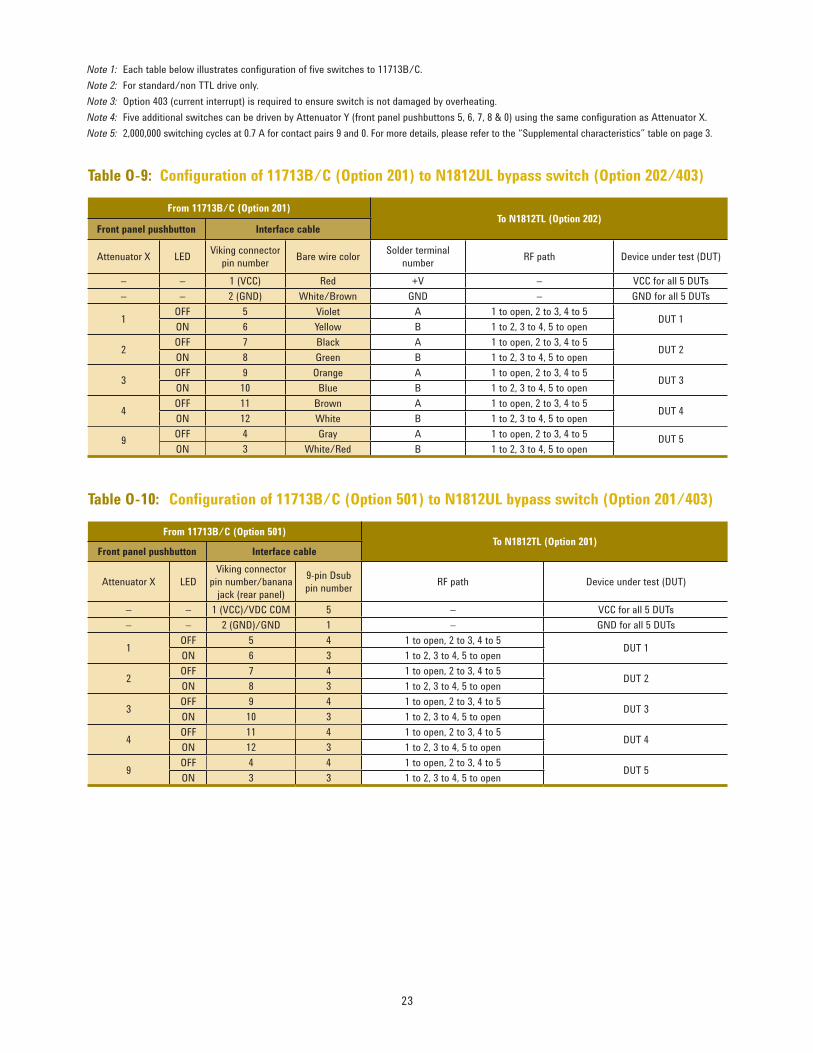
Table O-9: Confi guration of 11713B/C (Option 201) to N1812UL bypass switch (Option 202/403)
From 11713B/C (Option 201)To N1812TL (Option 202)
Front panel pushbutton Interface cable
Attenuator X LEDViking connector
pin numberBare wire color
Solder terminal
numberRF path Device under test (DUT)
– – 1 (VCC) Red +V – VCC for all 5 DUTs
– – 2 (GND) White/Brown GND – GND for all 5 DUTs
1OFF 5 Violet A 1 to open, 2 to 3, 4 to 5
DUT 1ON 6 Yellow B 1 to 2, 3 to 4, 5 to open
2OFF 7 Black A 1 to open, 2 to 3, 4 to 5
DUT 2ON 8 Green B 1 to 2, 3 to 4, 5 to open
3OFF 9 Orange A 1 to open, 2 to 3, 4 to 5
DUT 3ON 10 Blue B 1 to 2, 3 to 4, 5 to open
4OFF 11 Brown A 1 to open, 2 to 3, 4 to 5
DUT 4ON 12 White B 1 to 2, 3 to 4, 5 to open
9OFF 4 Gray A 1 to open, 2 to 3, 4 to 5
DUT 5ON 3 White/Red B 1 to 2, 3 to 4, 5 to open
Table O-10: Confi guration of 11713B/C (Option 501) to N1812UL bypass switch (Option 201/403)
From 11713B/C (Option 501)To N1812TL (Option 201)
Front panel pushbutton Interface cable
Attenuator X LED
Viking connector
pin number/banana
jack (rear panel)
9-pin Dsub
pin numberRF path Device under test (DUT)
– – 1 (VCC)/VDC COM 5 – VCC for all 5 DUTs
– – 2 (GND)/GND 1 – GND for all 5 DUTs
1OFF 5 4 1 to open, 2 to 3, 4 to 5
DUT 1ON 6 3 1 to 2, 3 to 4, 5 to open
2OFF 7 4 1 to open, 2 to 3, 4 to 5
DUT 2ON 8 3 1 to 2, 3 to 4, 5 to open
3OFF 9 4 1 to open, 2 to 3, 4 to 5
DUT 3ON 10 3 1 to 2, 3 to 4, 5 to open
4OFF 11 4 1 to open, 2 to 3, 4 to 5
DUT 4ON 12 3 1 to 2, 3 to 4, 5 to open
9OFF 4 4 1 to open, 2 to 3, 4 to 5
DUT 5ON 3 3 1 to 2, 3 to 4, 5 to open
Note 1: Each table below illustrates confi guration of fi ve switches to 11713B/C.
Note 2: For standard/non TTL drive only.
Note 3: Option 403 (current interrupt) is required to ensure switch is not damaged by overheating.
Note 4: Five additional switches can be driven by Attenuator Y (front panel pushbuttons 5, 6, 7, 8 & 0) using the same confi guration as Attenuator X.
Note 5: 2,000,000 switching cycles at 0.7 A for contact pairs 9 and 0. For more details, please refer to the “Supplemental characteristics” table on page 3.

24
Table O-11: Confi guration of 11713B/C (Option 201) to N1811TL bypass switch (Option 202/403)
From 11713B/C (Option 201)To N1812UL (Option 202)
Front panel pushbutton Interface cable
Attenuator X LEDViking connector
pin numberBare wire color
Solder terminal
numberRF path Device under test (DUT)
– – 1 (VCC) Red +V – VCC for all 5 DUTs
– – 2 (GND) White/Brown GND – GND for all 5 DUTs
1OFF 5 Violet A 1 to 2, 3 to 4
DUT 1ON 6 Yellow B 1 terminated, 2 to 3, 4 to open
2OFF 7 Black A 1 to 2, 3 to 4
DUT 2ON 8 Green B 1 terminated, 2 to 3, 4 to open
3OFF 9 Orange A 1 to 2, 3 to 4
DUT 3ON 10 Blue B 1 terminated, 2 to 3, 4 to open
4OFF 11 Brown A 1 to 2, 3 to 4
DUT 4ON 12 White B 1 terminated, 2 to 3, 4 to open
9OFF 4 Gray A 1 to 2, 3 to 4
DUT 5ON 3 White/Red B 1 terminated, 2 to 3, 4 to open
Table O-12: Confi guration of 11713B/C (Option 501) to N1811TL bypass switch (Option 201/403)
From 11713B/C (Option 501)To N1812UL (Option 201)
Front Panel Pushbutton Interface Cable
Attenuator X LED
Viking connector
pin number/banana
jack (rear panel)
9-pin Dsub
pin numberRF path Device under test (DUT)
– – 1 (VCC)/VDC COM 5 – VCC for all 5 DUTs
– – 2 (GND)/GND 1 – GND for all 5 DUTs
1OFF 5 4 1 to 2, 3 to 4
DUT 1ON 6 3 1 terminated, 2 to 3, 4 to open
2OFF 7 4 1 to 2, 3 to 4
DUT 2ON 8 3 1 terminated, 2 to 3, 4 to open
3OFF 9 4 1 to 2, 3 to 4
DUT 3ON 10 3 1 terminated, 2 to 3, 4 to open
4OFF 11 4 1 to 2, 3 to 4
DUT 4ON 12 3 1 terminated, 2 to 3, 4 to open
9OFF 4 4 1 to 2, 3 to 4
DUT 5ON 3 3 1 terminated, 2 to 3, 4 to open
Note 1: Each table below illustrates confi guration of fi ve switches to 11713B/C.
Note 2: For standard/non TTL drive only.
Note 3: Option 403 (current interrupt) is required to ensure switch is not damaged by overheating.
Note 4: Five additional switches can be driven by Attenuator Y (front panel pushbuttons 5, 6, 7, 8 & 0) using the same confi guration as Attenuator X.
Note 5: 2,000,000 switching cycles at 0.7 A for contact pairs 9 and 0. For more details, please refer to the “Supplemental characteristics” table on page 3.

25
Table O-13: Confi guration of 11713B/C (Option 201) to N1812UL bypass switch (Option 202/401/403)
From 11713B/C (Option 201)To N1812UL (Option 202)
Front panel pushbutton Interface cable
Attenuator X LEDViking connector
pin numberBare wire color Solder terminal number RF path Device under test (DUT)
– – 1 (VCC) Red +V – VCC for all 3 DUTs
– – 2 (GND) White/Brown GND – GND for all 3 DUTs
1 OFF 5 Violet A1 to open, 2 to 3, 4 to 5
DUT12 ON 7 Black B
1 ON 5 Violet A1 to 2, 3 to 4, 5 to open
2 OFF 7 Black B
3 OFF 9 Orange A1 to open, 2 to 3, 4 to 5
DUT24 ON 11 Brown B
3 ON 9 Orange A1 to 2, 3 to 4, 5 to open
4 OFF 11 Brown B
9 OFF 4 Gray A1 to open, 2 to 3, 4 to 5
DUT 30 ON 3 White/Red B
9 ON 4 Gray A1 to 2, 3 to 4, 5 to open
0 OFF 3 White/Red B
Table O-14: Confi guration of 11713B/C (Option 501) to N1812UL bypass switch (Option 201/401/403)
From 11713B/C (Option 501)To N1812UL (Option 201/401)
Front panel pushbutton Interface cable
Attenuator X LED
Viking connector
pin number/
banana jack
(rear panel)
9-pin Dsub
pin numberRF path Device under test (DUT)
– – 1 (VCC)/VDC COM 5 – VCC for all 3 DUTs
– – 2 (GND)/GND 1 – GND for all 3 DUTs
1 OFF 5 41 to open, 2 to 3, 4 to 5
DUT12 ON 7 3
1 ON 5 41 to 2, 3 to 4, 5 to open
2 OFF 7 3
3 OFF 9 41 to open, 2 to 3, 4 to 5
DUT24 ON 11 3
3 ON 9 41 to 2, 3 to 4, 5 to open
4 OFF 11 3
9 OFF 4 41 to open, 2 to 3, 4 to 5
DUT 30 ON 3 3
9 ON 4 41 to 2, 3 to 4, 5 to open
0 OFF 3 3
Note 1: Each table below illustrates confi guration of three switches to 11713B/C.
Note 2: For Option 401 (TTL drive) only.
Note 3: Option 403 (current interrupt) is required to ensure switch is not damaged by overheating.
Note 4: Two additional switches can be driven by Attenuator Y (front panel pushbuttons 5, 6, 7 & 8) using the same confi guration as Attenuator X.
Note 5: 2,000,000 switching cycles at 0.7 A for contact pairs 9 and 0. For more details, please refer to the “Supplemental characteristics” table on page 3.

26
Table O-15: Confi guration of 11713B/C (Option 201) to N1811TL bypass switch (Option 202/401/403)
From 11713B/C (Option 201)To N1812UL (Option 202)
Front panel pushbutton Interface cable
Attenuator X LEDViking connector
pin numberBare wire color Solder terminal number RF path Device under test (DUT)
– – 1 (VCC) Red +V – VCC for all 3 DUTs
– – 2 (GND) White/Brown GND – GND for all 3 DUTs
1 OFF 5 Violet A1 to 2, 3 to 4
DUT12 ON 7 Black B
1 ON 5 Violet A 1 terminated, 2 to 3, 4 to
open2 OFF 7 Black B
3 OFF 9 Orange A1 to 2, 3 to 4
DUT24 ON 11 Brown B
3 ON 9 Orange A 1 terminated, 2 to 3, 4 to
open4 OFF 11 Brown B
9 OFF 4 Gray A1 to 2, 3 to 4
DUT 30 ON 3 White/Red B
9 ON 4 Gray A 1 terminated, 2 to 3, 4 to
open0 OFF 3 White/Red B
Table O-16: Confi guration of 11713B/C (Option 501) to N1811TL bypass switch (Option 201/401/403)
From 11713B/C (Option 501)To N1812UL (Option 201/401)
Front panel pushbutton Interface cable
Attenuator X LED
Viking connector
pin number/
banana jack
(rear panel)
9-pin Dsub
pin numberRF path Device under test (DUT)
– – 1 (VCC)/VDC COM 5 – VCC for all 3 DUTs
– – 2 (GND)/GND 1 – GND for all 3 DUTs
1 OFF 5 41 to 2, 3 to 4
DUT12 ON 7 3
1 ON 5 41 terminated, 2 to 3, 4 to open
2 OFF 7 3
3 OFF 9 41 to 2, 3 to 4
DUT24 ON 11 3
3 ON 9 41 terminated, 2 to 3, 4 to open
4 OFF 11 3
9 OFF 4 41 to 2, 3 to 4
DUT 30 ON 3 3
9 ON 4 41 terminated, 2 to 3, 4 to open
0 OFF 3 3
Note 1: Each table below illustrates confi guration of three switches to 11713B/C.
Note 2: For Option 401 (TTL drive) only.
Note 3: Option 403 (current interrupt) is required to ensure switch is not damaged by overheating.
Note 4: Two additional switches can be driven by Attenuator Y (front panel pushbuttons 5, 6, 7 & 8) using the same confi guration as Attenuator X.
Note 5: 2,000,000 switching cycles at 0.7 A for contact pairs 9 and 0. For more details, please refer to the “Supplemental characteristics” table on page 3.

27
From 11713B/C (Option 001) To attenuators (Option 016)
Front panel pushbutton Interface cable 8494G/H 8495G/H 8496G/H 8495K 8497K
Attenuator X LEDViking connector
pin number
10-pin DIP
pin number Attenuation (dB)
– – 1 (VCC) 10 – – – – –
1OFF 5 1 0 0 0 0 0
ON 6 2 1 10 10 10 10
2OFF 7 5 0 0 0 0 0
ON 8 8 2 20 20 20 20
3OFF 9 4 0 0 0 0 0
ON 10 9 4 40 40 20 30
4OFF 11 6 0 – 0 0 0
ON 12 7 4 – 40 20 30
From 11713B/C (Option 101) To attenuators (Option 060)
Front panel pushbutton Interface cable 8494G/H 8495G/H 8496G/H 8495K 8497K
Attenuator X LEDViking connector
pin number
Viking
connector
pin number
Attenuation (dB)
– – 1 (VCC) 1 – – – – –
1OFF 5 5 0 0 0 0 0
ON 6 6 1 10 10 10 10
2OFF 7 7 0 0 0 0 0
ON 8 8 2 20 20 20 20
3OFF 9 9 0 0 0 0 0
ON 10 10 4 40 40 20 30
4OFF 11 11 0 – 0 0 0
ON 12 12 4 – 40 20 30
Note 1: Each table below illustrates the confi guration of one attenuator to the 11713B/C.
Note 2: One additional attenuator can be driven by Attenuator Y (front panel pushbuttons 5, 6, 7 & 8) using the same confi guration as Attenuator X.
Table P-1: Confi guration of 11713B/C (Option 001)
to 8494G/H, 8495G/H, 8496G/H, 8495K & 8497K programmable attenuators (Option 016)
Table P-2: Confi guration of 11713B/C (Option 101)
to 8494G/H, 8495G/H, 8496G/H, 8495K & 8497K programmable attenuators (Option 060)
From 11713B/C (Option 001) To attenuators
Front panel pushbutton Interface cable 84904K/L/M 84905M 84906K/L 84907K/L 84908M
Attenuator X LEDViking connector
pin number
10-pin DIP
pin number Attenuation (dB)
– – 1 (VCC) 10 – – – – –
1OFF 5 1 0 0 0 0 0
ON 6 2 1 10 10 10 5
2OFF 7 5 0 0 0 0 0
ON 8 8 2 20 20 20 10
3OFF 9 4 0 0 0 0 0
ON 10 9 4 30 30 40 20
4OFF 11 6 0 0 0
ON 12 7 4 30 30
Table Q: Confi guration of 11713B/C (Option 001)
to 84904K/L/M, 84905M, 84906K/L, 84907K/L & 84908M programmable attenuators
Confi guration Information for Attenuators

28
Figure 1. Option 001 viking connector to 10-pin DIP connector
Figure 2. Option 101 viking connector to viking connector
Measurement in millimeters
Measurement in inches
Interface Cable Drawings

29
Figure 3. Option 201 viking connector to 12-pin conductor cable, bare wire
Figure 4. Option 301 viking connector to 4 ribbon cables
Measurement in inches
Measurement in inches

30
Figure 5. Option 401 dual-viking connector to 16-pin DIP connector
Figure 6. Figure 6. Option 501 viking connector to (4) 9-pin Dsub connectors
Measurement in inches
Measurement in inches

31
Figure 7. Option 601 viking connector to 16-pin DIP connector
Measurement in inches

32
12
11 10
9
8
76
5
4
3
2
1
P1connectorfront view
Approx.(54)
(6)
3 wires
A+Aview
P1
531
SW 1
SW 1
SW 1
SW 1
P2
P3
P4
P5
A
A
Figure 8. Option 701 viking connector to 14-pin DIP connector
Figure 9. Option 801 viking connector to (4) 10-pin DIP connectors
Measurement in millimeters
Measurement in inches