agilent 81150a and 81160a pulse function arbitrary noise ... · pulse function arbitrary noise...
TRANSCRIPT

Agilent 81150A and 81160APulse Function Arbitrary NoiseGenerators
Accurate Pulse, Function Arbitrary and NoiseGeneration in a Single Box
Application Note, Version 1.3
• Noise and Jitter Tolerance Testing
• Noise Source for SATA
• Gigabit Ethernet
• Radar Communication Systems
• Nanotechnology
• Reactor Stability Testing
• IQ Modulation

2
Introduction
The Agilent 81150A and 81160A pulse function arbitrary noise generators focus on engineers in manufacturing, R&D and
education across the industry.
The new class of instrument combines four instruments in one:
• The high precision pulse generator is enhanced with a versatile signal generator, offering distortion capabilities to
stress your device to its limit.
• The function arbitrary generator provides versatile waveforms and modulation capabilities to adapt the signal to
devices requirements.
• The optional pattern generator allows analog, digital and mixed signal device tests with ideal and real-world pattern.
• The noise generator combines two required extremes: random noise and repeatable noise with very long repetition
rates for simple problem identification.
The versatile and precise instruments are a must have for every lab as many different devices under test can be stimu-
lated.
In addition, the 81150A and 81160A let you inject noise for testing serial bus standards.
Both of them provide accurate and accelerated insight into your device through ideal and real-world signals. Just generate
the signal you need—because just enough is not enough.
Device emulation, precise clock source,
noise immunity testing, simulation of custom-
er design, DC brushless motors, sonar testing,
modulator testing, component testing, mixed
signal devices, trigger…

3
Jitter and noise cause misalignment of edges and levels,
resulting in data errors. Noise is by its nature unpredictable
because it can have many different causes, from signal
interference caused by sudden voltage changes, to distor-
tions introduced during transmission.
It is important to be able to simulate noise-based malfunc-
tions, for example to identify the additive noise produced
by receiving systems—it is cheaper to lower the noise
figure than to increase the transmitter power. The 81150A
and 81160A let you control the quality of the noise and test
different cases according to various specifications.
Gaussian white noise is a good approximation of many
real-world situations and creates mathematically traceable
models, with statistically independent values.
The crest factor is an indicator of signal quality. The higher
the crest factor is, the more noise is used. The 81150A and
81160A provide four selectable crest factors using
Vp/RMS or Vpp/RMS. The Vp/RMS definition is used by
both instruments.
RX jitter tolerance tests conducted by a noise source with
a low crest factor might let you pass the test even if the
device is momentarily substandard.
Figure 1. Gaussian curve of crest factor 3 and 7
Different crest factors
BER and the different crest factors
Figure 2. Bath tub with different crest factors
The crest factor of seven corresponds to a BER 10–23 which
is required by the serial bus standards. The noise provided
by the instruments is triggerable, and the signal repetition
rate is 20 days for the 81160A and 26 days for the 81150A.
This guarantees randomness and repeatability. The 81150A
and 81160A let you defi ne any arbitrary distribution,
which is ideal if you need your noise with a non-Gaussian
distribution. Both instruments provide deterministic white
noise either with Gaussian or arbitrary distribution.
Noise and Jitter Tolerance Testing
CF=5
BER
BER and the different crest factors
10 -6
10 -12
CF=7
VppVpeak
Crest factor = Vpp/RMSIncidence
Voltage
δMean
CF 7
CF 3
RMS
Vpeak/RMS

4
Random jitter
The Agilent 81150A and 81160A pulse function arbitrary
noise generators provide deterministic Gaussian white
noise, with a signal repetition of 20 days for the 81160A
and 26 days for the 81150A. You can decide on any
arbitrary distribution and trigger the noise to start when
you need it.
You can select the required crest factor of seven—using
Vp/RMS. This crest factor corresponds to a BER 10 -12.
Figure 4. Noise probability function screen
Sinusoidal jitter
For the sinusoidal jitter select a sine wave and set the
required frequency. Calibrate the jitter by adjusting the
amplitude and observing the jitter on the jitter measure-
ment device.
The 81150A and 81160A are integrated in the Agilent test
automation software platform, N5990A Option 103. The
software provides compliance and interoperability testing
and fully controls the test setup including sinusoidal and
random noise.
Serial ATA (SATA) is the next generation personal com-
puter storage interface. SATA I operates at 1.5 Gb/s, SATA
II at 3 Gb/s and SATA III at 6 Gb/s.
In order to perform receiver jitter tolerance testing on
SATA transceivers, several pieces of equipment are
needed.
So far, an Agilent 33250A was needed for the sinusoidal jit-
ter and a noise source for the random/deterministic jitter.
The jitter is injected to the delay control in line of a pattern
generator, which generates the signal with the appropriate
frequency.
The 81150A and 81160A can generate both jitter types in
one instrument, thus providing a cost-effective solution
as two instruments with a power divider are no longer
required.
Figure 3. SATA receiver test set up
RJ source
C-H-S FER
counter
00B & “BIST L”
source
81134A pattern
generator
Noise33250A
SMA to SATA
fixture
DSO 80000
oscilloscope
SMA
cables
Power divider
S-ATA
cable
8/10bTX
Retiming
Scramble
Scramble
DUT
10/8b
00B detect
RX
Same equipment
used for 00B tests
TX
RX
RX
TX
Frame error rate counter
Framed COMP pattern
Turn on test mode
SJ source
Setup calibration
Noise Source for SATA

5
Stressing Gigabit Ethernet Receivers
Figure 5. PAM-5 signal with 0.1 VPP noise
Figure 6. Attenuation, distortion, noise and delays can be added to the signal to emulate real-world conditions
1000Base-T Ethernet is a proven and economic technology
and used in many devices. 5-level pulse amplitude modu-
lated (PAM-5) signals are transmitted over unshielded,
balanced, twisted-pair copper cable at data rates of 1 Gb/s.
Its great advantage—that it can reuse existing
10/100Base-T infrastructures—is also its greatest poten-
tial weakness.
Inadequate cabling can introduce distortions and threaten
signal integrity. It is crucial to be able to quantify phe-
nomena like noise, delays and distortions to characterize
receivers. At theses speeds, the traditional ways of
examining these, (e.g. using a 1000Base-T transmitter as
a source and a cable plant to degrade the signal) are not
suitable because they are expensive, time-consuming and
may even be unreliable.
The 81160A is an affordable way of characterizing Gigabit
Ethernet receivers quickly and reliably because it offers:
A unique combination of pulse pattern generator and
versatile arbitrary waveform generator at the needed speed
to generate PAM-5 signals for 1000Base-T. Full control
over the probing signal, to alter the parameters and explore
borderline conditions, or troubleshoot areas where a
device fails to meet the specifications. An integrated noise
generator with different crest factors, which generates
random and repeatable noise. Glitch-free change of timing
parameters, such as e.g. delay and frequency, for efficient
testing without reboots and resynchronizations.
The signal is set up as an arbitrary waveform. This can be
either done on the instrument, using the Agilent BenchLink
Waveform Builder Pro software, or with a Matlab script.
Stress can be easily achieved by adapting the rise time from
5.12 s to 4.61 ns.
T R
R T
Hybrid
DistortionAttenuationNoise Delay
TDX
Crosstalk
RDX
Hybrid

6
Radar Communication Systems in the Aviation and Military Industries
Agilent pulse generators are often used for testing radar
communication systems in the military industry and the
aviation industry. The application note, “Radar Distance
Test to Airborne Planes” (5968-5843E), describes the
usage of the 81110A.
To determine the distance of a target object e.g. an
airborne plane, a triggered pulse train is sent from the
control tower’s radar system to an airborne plane. The
plane responds with a standard signature which is sent
back to the control tower. The tower receives the signal,
recognizes the signature, and then analyzes the delay
to determine the distance between the tower and the
airborne plane.
Important functionality:
• Rise/fall times 2.5 ns
• Triggered pulse stream internally or via an external
signal
• Burst of pulse stream
• Small duty cycles
• Highest possible frequency accuracy
The 81150A and 81160A can be used to simulate the radar
signal. Varying the delay from the external trigger to the
start of the output signal can simulate various distances
from the control tower.
Figure 7. Radar distance test to airborne planes
Besides the precise signal with accurate rise and fall times
of 2.5 ns, a distortion of the signal is interesting.
Figure 8. Example settings channel 1
The crest factor is a sign of signal quality, the higher the
crest factor the more complete—real world—noise is
available. The channel add functionality can add the signal
of channel two to channel one. So any modulation or noise
with different crest factors can be added to the precise
signal.
Figure 9. Channel 2 with selected crest factor of 4.8

7
Control the Amount of Energy for Nanotechnology Devices
Nanotechnology starts to gain importance in the semi-
conductor technologies through denser memory, faster
processors and electronic devices that need less power.
Engineers need to fully characterize devices and materials,
which requires:
• Small voltage
• Accurate and repeatable measurements
The measurement techniques and instruments require
minimal noise and other sources of error that might inter-
fere with the signal.
It is very important to control the amount of energy during
the measurement, otherwise you damage the device under
test.
Short pulses and bursts of pulses are important to avoid
heat generation. Small duty ratio allows the device under
test to cool down and short pulse width avoids leakage
through gate oxide.
The Agilent 81150A provides:
• Pulse width 4.16 ns to (period – 4.16 ns)
• Transition times 2.5 ns to 1000 s (10/90)
• Variable rise and fall time
• Differential output
• Pulse width modulation for real stress test
The Agilent 81160A:
• Pulse width 1.50 ns (period – 1.50 ns)
• Transition times 1.0 ns to 1000 s (10/90)
• Variable rise and fall time
• Differential output
• Pulse width modulation for real stress test
The 81150A and 81160A are pulse generators, an instru-
ment typically used for this kind of measurements. They
guarantee accurate and repeatable measurements.
The combination of the pulse and function arbitrary
generator allows special stress tests like the pulse width
modulation. The modulation of the duty cycle allows for
control of the amount of power, which is critical for this
type of device.
The 81150A and 81160A include a noise generator as well.
Through channel add, noise can be added to the pulse or
pulse width modulated signal. By adding different amounts
of noise you can stress your device to its limit.
Figure 10. Setting up a pulse
Figure 11. Setting up a pulse width modulation
Figure 12. Setting up noise

8
Signal Emulation for Nuclear Power Stations
Simulation solutions for reactor stability testing are very
sensitive. It is extremely important that the monitoring
system is well tested and fault events generate an alarm.
When barium sticks are pulling out, pulse quantity
increases exponentially. The verification of the alarm and
monitoring system requires generators to simulate an
exponential increase of pulse frequency whereby the pulse
duration has to be consistent.
Required signal:
|____________|________|____|__|__|_||
T(0) T(1) T(2) T(3)T(4) ...
T(n) must vary in exponential law. The pulse duration
should be constant. The period between pulses is expo-
nential.
Previously, both a pulse generator and an arbitrary genera-
tor were needed for this application, however, the 81150A
and 81160A combine an Agilent proven pulse generator
and a function arbitrary generator, meaning only one
instrument is needed.
The first channel provides the pulses.
The second channel provides a frequency sweep and trig-
gers the first channel.
The 81150A and 81160A allow the reduction from two
to one instrument which corresponds with higher test
efficiency.
For this application the two channel version is needed. The
channels can work entirely independently as required with
this application, but the channels can be coupled with a
defined delay as well.
Figure 13. Pulse generator configuration screen
Figure 14. Frequency sweep configuration screen

9
Whether testing a wide bandwidth modulator, or using an
existing modulator to provide test signals for other compo-
nents in the transmission channel, you need differential,
in-phase and quadrature (IQ) baseband signals.
In cases where you need to test beyond the standards
and predefined protocols, you need more flexibility to
generate or control the amplitude, phase, and frequency
of your signals than a vector signal generator can typically
provide. The Agilent 81160A Pulse Function Arbitrary Noise
Generator has two, differential ports that let you inde-
pendently control signal levels, frequency (up to 500 MHz
in sine mode), offset voltages, and the phase difference
between the ports. In arbitrary mode, up to 330 MHz is
available separately for the I and Q channels, which means
up to 660 MHz IQ modulation bandwidth 1. This makes it
easy to set up and vary the parameters you need to stress
your DUT comprehensively.
Figure 15. Typical set-up to test an IQ Modulator
Testing Wide Bandwidth In-Phase and Quadrature Modulation in RF and Microwave Communications Channels
1. For test set-ups that do not need the full bandwidth of the
81160A, the 81150A Pulse Function Arbitrary Noise Generator
offers the same functionality with 330 MHz bandwidth in sine
mode, or 120 MHz in arbitrary mode for up to 240 MHz IQ
modulation bandwidth.
Testing IQ modulators
For example, when testing or characterizing an IQ modula-
tor, you may need to measure quadrature or DC offset
errors, or phase or gain imbalances, to be able to optimize
the Error Vector Magnitude.
• You can first use single tone baseband signals, adjusting
the amplitudes, frequencies, voltage and phase offsets
independently to stress the modulator.
• Later you can test the response to multilevel signals
(programmed, for example, in MatLab) to make the most
of the 14-bit vertical resolution of the function arbitrary
generator 2.
• You can introduce further stress by introducing a noise
component, using the built-in noise generator.
2. If this is an important part of the test, it may be worth con-
sidering the Agilent 81180B or M8190A Arbitrary Waveform
Generators.
OscilloscopeAgilent Infiniium Oscilloscope with VSA, or similar
Agilent 81160A Pulse Function Arbitrary Noise Generator
RF or microwave source as local oscillator (optional)Agilent N5183A MXG Microwave Analog Signal Generator
(up to 40 GHz), or similar
DUT
10
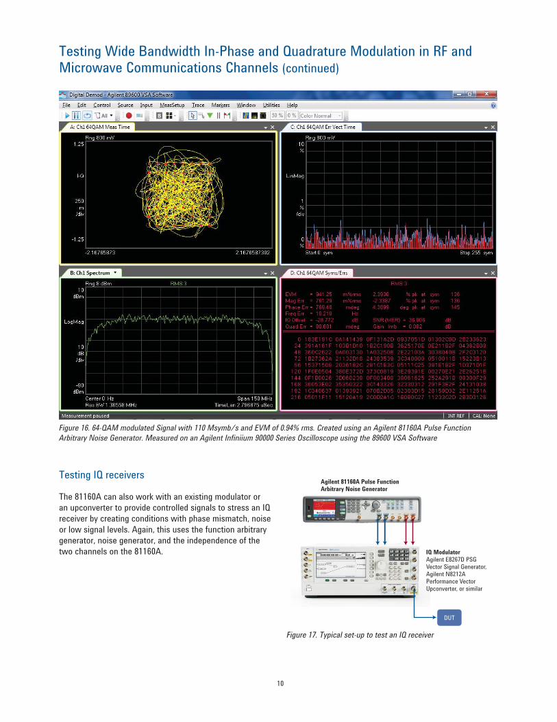
Figure 16. 64-QAM modulated Signal with 110 Msymb/s and EVM of 0.94% rms. Created using an Agilent 81160A Pulse Function
Arbitrary Noise Generator. Measured on an Agilent Infiniium 90000 Series Oscilloscope using the 89600 VSA Software
Testing Wide Bandwidth In-Phase and Quadrature Modulation in RF and Microwave Communications Channels (continued)
Testing IQ receivers
The 81160A can also work with an existing modulator or
an upconverter to provide controlled signals to stress an IQ
receiver by creating conditions with phase mismatch, noise
or low signal levels. Again, this uses the function arbitrary
generator, noise generator, and the independence of the
two channels on the 81160A.
Figure 17. Typical set-up to test an IQ receiver
Agilent 81160A Pulse Function Arbitrary Noise Generator
IQ ModulatorAgilent E8267D PSG Vector Signal Generator, Agilent N8212A Performance Vector Upconverter, or similar
DUT

11
Configuration Guide for 81150A
Part Description
#001 1-channel 120 MHz pulse function arbitrary noise generator
#002 2-channel 120 MHz pulse function arbitrary noise generator
#1A7 ISO17025 calibration and certificate
#Z54 Z540.3 calibration and certificate
#PAT License for 120 Mbit/s pattern generator
Accessories included
Certificate of calibration
Local power cord
USB cable
Product CD (User Guide, Getting Started Guide, IVI-COM driver, examples for remote access)
Optional accessories
#DOC Printed documentation. Includes printed Getting Started Guide and printed User Guide
#1CP Rack mount kit
#R1280A Additional 2-years warranty (3-years total)
Upgrades for 81150A
81150AU
#PAT License for pattern generator
#DOC Printed documentation
#EHD Fixture for 100 Mbit ethernet and HDMI 1.4
Part Description
#001 1-channel 330 MHz pulse function arbitrary noise generator
#002 2-channel 330 MHz pulse function arbitrary noise generator
#1A7 ISO17025 calibration and certificate
#Z54 Z540.3 calibration and certificate
#330 License for 330 Mbit/s pattern generator
#660 License for 660 Mbit/s pattern generator
Accessories included
Certificate of calibration
Local power cord
USB cable
Product CD (User Guide, Getting Started Guide, IVI-COM driver, examples for remote access)
Optional accessories
#DOC Printed documentation. Includes printed Getting Started Guide and printed User Guide
#1CP Rack mount kit
#R1280A Additional 2-years warranty (3-years total)
Upgrades for 81160A
81160AU
#330 License for 330 Mbit/s pattern generator
#660 License for 660 Mbit/s pattern generator
#326 License for upgrade from 330 Mbit/s to 660 Mbit/s pattern generator
#DOC Printed documentation
Configuration Guide for 81160A

Agilent Email Updates
www.agilent.com/find/emailupdates
Get the latest information on the
products and applications you select.
www.lxistandard.org
LAN extensions for Instruments puts
the power of Ethernet and the Web
inside your test systems. Agilent
is a founding member of the LXI
consortium.
Agilent Channel Partners
www.agilent.com/find/channelpartners
Get the best of both worlds: Agilent’s
measurement expertise and product
breadth, combined with channel
partner convenience.
For more information on Agilent Technologies’ products, applications or services, please contact your local Agilent
office. The complete list is available at:
www.agilent.com/find/contactus
AmericasCanada (877) 894 4414 Brazil (11) 4197 3600Mexico 01800 5064 800 United States (800) 829 4444
Asia PacificAustralia 1 800 629 485China 800 810 0189Hong Kong 800 938 693India 1 800 112 929Japan 0120 (421) 345Korea 080 769 0800Malaysia 1 800 888 848Singapore 1 800 375 8100Taiwan 0800 047 866Other AP Countries (65) 375 8100
Europe & Middle EastBelgium 32 (0) 2 404 93 40 Denmark 45 45 80 12 15Finland 358 (0) 10 855 2100France 0825 010 700* *0.125 €/minute
Germany 49 (0) 7031 464 6333 Ireland 1890 924 204Israel 972-3-9288-504/544Italy 39 02 92 60 8484Netherlands 31 (0) 20 547 2111Spain 34 (91) 631 3300Sweden 0200-88 22 55United Kingdom 44 (0) 118 927 6201
For other unlisted countries: www.agilent.com/find/contactusRevised: January 6, 2012
Product specifications and descriptions in this document subject to change without notice.
© Agilent Technologies, Inc. 2012Published in USA, August 13, 20125989-7860EN
www.agilent.comwww.agilent.com/find/81150www.agilent.com/find/81160
For the latest version of this document, please visit our website at www.agilent.com/find/81150 or www.agilent.com/find/81160 and go to the product library.
Related literature Publication
number
Agilent 81150A and 81160A Pulse Function Arbitrary Noise Generators Data Sheet
5989-6433EN
Agilent 81150A and 81160A Pulse Function Arbitrary Noise Generators Demo Guide
5989-7718EN
Agilent 81150A Pulse Function Arbitrary Noise Generator Flyer
5989-7720EN
Agilent 81150A Pulse Function Arbitrary Noise Generator Quick Fact Sheet
5990 4565EN
Agilent 81160A Pulse Function Arbitrary Noise Generator Quick Fact Sheet
5990-6984EN
Pulse Pattern and Function Arbitrary Generators Brochure
5980-0489E
81150A and 81160A Arbitrary Bit-Shape Pattern Generator Application Note
5990-8822EN
Stressing 1GbE Receivers on the Physical Layer Application Note
5990 9346EN
Agilent Advantage Services is committed
to your success throughout your equip-
ment’s lifetime. To keep you competitive,
we continually invest in tools and
processes that speed up calibration and
repair and reduce your cost of ownership.
You can also use Infoline Web Services
to manage equipment and services more
effectively. By sharing our measurement
and service expertise, we help you create
the products that change our world.
www.agilent.com/quality
www.agilent.com/find/advantageservices
Quality Management SystemQuality Management SysISO 9001:2008
Agilent Electronic Measurement Group
DEKRA Certified