agom seismic isolation · consequence the isolated structures can be designed or by a simple single...
TRANSCRIPT

0008ENG Rev.07 25/01/2018
SEIS
MIC
IS
OLA
TIO
N
AGOM INTERNATIONAL SRL Via Mesero, 12 – 20010 Ossona (MI) – Italy - www.agom.it
PH.: +39 02 9029111 – FAX: +39 02 9010201 – [email protected]

Pag 2
Seismic isolation strategy
The usual anti seismic design is based on the structural ductility that is the ability to undertake extensive plastic deformations which dissipate energy by hysteresis. In this kind of design large structural damages are allowed. Consequently, even if the structure collapse is prevented, expensive repairs are necessary after major earthquakes. No protection is guaranteed to the goods inside the structures.
However, for strategic structures, such as hospitals, power plants, control rooms, and primary bridges, the functionality after catastrophic events is a primary goal to be guaranteed in addition to the structural integrity.
The operating requirements after an earthquake event can be a task even more severe than the structure collapse prevention: for example, in a hospital, the large acceleration occurring during an earthquake
could damage the electronic instruments and the service networks (gas pipes, etc) even if the structure integrity is not largely affected.
On the contrary, the seismic isolation design, based on the concept of reducing the seismic energy transferred to
structures, has proved to be the most effective design technology for protection against earthquakes; indeed not only the structure’s integrity is guaranteed but also that of the goods inside.
The whole isolation of a structure is obtained by placing adequate elastic supports in suitable positions in order to disentangle the ground from the structure allowing relative displacements.
The isolation principle is very simple: the idea is to shift the structure vibration period from low values (typically ranging from 0.3 to 1 seconds for a fixed base structure) where the ground acceleration is pronounced to longer periods (2-3 seconds) where the acceleration is highly reduced as shown in the figure below, where the ground acceleration spectra are plotted versus the vibration
period.
Additional acceleration reduction can be obtained by adding damping capacity to the isolators (energy dissipation).
Since larger displacements are due to longer periods and acceleration reductions, the goals of seismic isolation system design are mainly two:
• reducing acceleration to a target value so as to avoid structural damages and to ensure the functionality even under catastrophic earthquakes, using a simple and cheaper design of the
structure
• keeping the relative displacement between the ground and the structure to acceptable values so as to allow a cost-effective design of isolators, joints and flexible pipe connections.
With "seismic isolation design" it is possible to isolate not only new but also existing constructions through the insertion of special devices between the base of the structure and its foundations.
This concept is the key-point of the base isolation systems designed and manufactured by AGOM, based on rubber bearings made of high damping compounds (E-safe HDRB) and/or with a damping lead core (E-safe LRB).
All the movements and displacements due to the earthquake are concentrated at the base of the structure avoiding strengthening the whole structure itself with different type of device; in this way any widespread damages are prevented.
The isolators are usually installed at the base of each pier or, in general, under each vertical bearing
Displacement design spectrum
0
0.002
0.004
0.006
0.008
0.01
0.012
0.014
0.016
0.018
0.02
0.00 0.50 1.00 1.50 2.00 2.50 3.00 3.50 4.00
Period (sec)
Dis
pla
cem
en
t
5%
10%
16%
30%
Increasing period
Increasing damping
Acceleration design spectrum
0.0000
0.1000
0.2000
0.3000
0.4000
0.5000
0.6000
0.00 0.50 1.00 1.50 2.00 2.50 3.00 3.50 4.00
Period (sec)
Accele
rati
on 5%
10%
16%
30%
Increasing period
Increasing damping
Pag 3
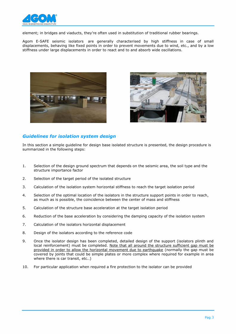
element; in bridges and viaducts, they’re often used in substitution of traditional rubber bearings.
Agom E-SAFE seismic isolators are generally characterised by high stiffness in case of small displacements, behaving like fixed points in order to prevent movements due to wind, etc., and by a low stiffness under large displacements in order to react and to and absorb wide oscillations.
Guidelines for isolation system design
In this section a simple guideline for design base isolated structure is presented, the design procedure is summarized in the following steps:
1. Selection of the design ground spectrum that depends on the seismic area, the soil type and the structure importance factor
2. Selection of the target period of the isolated structure
3. Calculation of the isolation system horizontal stiffness to reach the target isolation period
4. Selection of the optimal location of the isolators in the structure support points in order to reach, as much as is possible, the coincidence between the center of mass and stiffness
5. Calculation of the structure base acceleration at the target isolation period
6. Reduction of the base acceleration by considering the damping capacity of the isolation system
7. Calculation of the isolators horizontal displacement
8. Design of the isolators according to the reference code
9. Once the isolator design has been completed, detailed design of the support (isolators plinth and local reinforcement) must be completed. Note that all around the structure sufficient gap must be
provided in order to allow the horizontal movement due to earthquake (normally the gap must be covered by joints that could be simple plates or more complex where required for example in area where there is car transit, etc..)
10. For particular application when required a fire protection to the isolator can be provided

Pag 4
ISOLATION SYSTEM DESIGN
SELECTION OF THE DESIGN GROUND SPECTRUM THAT DEPENDS ON THE
SEISMIC AREA, THE SOIL TYPE AND THE STRUCTURE IMPORTANCE FACTOR
SELECTION OF THE TARGET PERIOD OF THE ISOLATED STRUCTURE
CALCULATION OF THE ISOLATION SYSTEM HORIZONTAL STIFFNESS
TO REACH THE TARGET ISOLATION PERIOD
CALCULATION OF THE STRUCTURE BASE
ACCELERATION AT THE TARGET ISOLATION PERIOD
CALCULATION OF THE ISOLATORS HORIZONTAL
DISPLACEMENT
REDUCTION OF THE BASE ACCELERATION BY CONSIDERING THE DAMPING CAPACITY OF
THE ISOLATION SYSTEM
DESIGN OF THE ISOLATORS ACCORDING TO THE REFERENCE
CODE
SELECTION OF THE OPTIMAL LOCATION OF THE ISOLATORS IN THE STRUCTURE
SUPPORT POINTS IN ORDER TO REACH, AS MUCH AS IS POSSIBLE, THE COINCIDENCE
BETWEEN THE CENTER OF MASS AND STIFFNESS

Pag 5
Lead core rubber bearings – E-safe LRB
Lead core rubber bearings are so named due to the insertion of one or more lead cylinders into the rubber bearing. The lead cylinder provides very effective damping during extreme movements. The Agom E-SAFE lead core rubber bearings consist of multiple elastomer layers separated by reinforcing
steel plates moulded to the rubber, and can be manufactured in a rectangular or circular shape according to customer requirements. The lead insert in the core of the bearing dissipates the energy of the earthquake while the rubber, reinforced with steel plates, provides stability, supports the structure and isolates vibrations.
This type of seismic isolator is able to support live vertical loads and low displacement horizontal loads (e.g. wind effects), while protecting and isolating the structure by absorbing the impact of earthquake tremors and by reducing oscillations.
After an earthquake the restorative properties of the rubber layers return the building to its original position.
During the design and engineering phase the type of rubber compound with the appropriate G modulus value is selected according to the installation’s technical requirements and project specifications.
The damping factor of lead core rubber bearings can be higher then 30%.
High damping rubber bearings –E safe HDRB
The Agom E-SAFE high damping rubber bearings HDRB consist of multiple elastomer layers made of special dissipative rubber compounds, separated by reinforcing steel plates moulded to the rubber layer, and can be manufactured in a rectangular or circular shape according to customer requirements.
In the E-SAFE HDRB isolator, the energy is dissipated by hysteresis by the special rubber compound during the cycles of horizontal deformation of the insulator.
After an earthquake the excellent restorative properties of the rubber layers return the building to its original position.
The damping factor of HDRB can reach 10-16%.
E-SAFE high damping rubber bearings HDRB and its response cycles, horizontal load - displacement
E-SAFE lead core rubber bearing LRB (full scale device)
E-SAFE lead core rubber bearing LRB (section of a scaled sample)

Pag 6
Comparison of seismic isolators performances
LRB lead core rubber bearing
HDRB high damping rubber
bearing
MLRB multi layer low damping
rubber bearings
Damping ratio 25-30% 10-16% 4%
Horizontal stiffness High Low-Medium Low-Medium
Vertical load High High High
Horizontal displacement Medium-High High Medium
Recentering capacity Medium High High
Advantages of using Agom E-Safe isolators
The Agom E-SAFE HDRB and LRB seismic isolators fulfil the following requirements:
a. Transmit the vertical loads due to permanent and accidental effects in seismic condition; it is possible to cover a wide range of loads about up to 40000 kN
b. Very wide range of plan diameters (from 300 to 1500 mm)
c. Support the horizontal loads due to service load conditions with low displacements
d. Energy dissipation capacity up to 30%1 (16% for HDRB) equivalent viscous damping value to reduce the horizontal displacement of the isolated structure respect to the ground
e. Guarantee the stability at the maximum horizontal displacement due to
seismic excitation; it is possible to guarantee a wide range of displacements function of the applied vertical load and horizontal stiffness
Advantages of using Agom E-SAFE HDRB and LRB seismic isolators:
a. Under the same seismic excitation, Agom base isolated structures are less affected or even free from damages: this avoids closures or repairing of the constructions thereby protecting structures, installations, strategic equipments and, above all, human lives.
b. Very well known technology with 20-30 years of experience in many application both for buildings and for bridges all around the world
c. Very simple maintenance mainly limited to a periodic visual inspection for all the design life
d. High capacity of reducing the seismic forces on the structure; this implies simplification of the structure design and reduction of the structure construction
costs
e. Very easy simulation of the device response by linear modelling; as a consequence the isolated structures can be designed or by a simple single degree of freedom approach for regular structures (according to international design codes) or by a linear dynamic analysis (response spectrum or time
history) by modelling the structure using a finite element code including also the isolators by proper elements in the simulation.
1 normally 30% of equivalent viscous damping value is the maximum damping allowed to model the device as linear according to the international design
standards; if an higher value is required a dynamic non linear time history analysis should be performed in order to simulate the structural system response
during earthquakes
FREE FROM
DAMAGES
VERY SIMPLE
MAINTENANCE
SEISMIC
FORCES
REDUCTION
LINEAR
MODELLING
N ed, max
UP TO
40000 kN
WIDE RANGE
Ø1500 MM
HIGH
STABILITY
DAMPING
FACTOR
UP TO 30%
Pag 7
International standards
The behaviour of the Agom E-SAFE isolator and the technical and mechanical features of the materials used to manufacture them, comply to the requirements of international standards as Italian OPCM 3274 and following amendments in addition to CNR 10018 standard, European codes on construction EN1998-1 and EN 1998-2, European code on anti seismic devices prEN15129.
Agom can also design and manufacture seismic isolators complying with different design requirements prescribed by other international rules and standard.
Fixing types
Usually all the E-SAFE isolators are equipped with suitable anchor bars for anchoring purpose to lower and upper structure.
To improve the E-SAFE isolators replacement with minimal up-lift of the structure, suitable Agom interconnecting quick devices QD are provided, as shown in the following pictures.
Seismic isolators with bolts can be supplied for connection with steel structures.
Manufacturing and Quality
Agom designs and manufactures entirely in house all the E-SAFE isolators LRB and HDRB, with a controlled vertically integrated process. Every single component is moulded, mechanically worked and assembled by fully qualified and trained workers at the Agom factory with regular external inspections according to international standards and under strict ISO 9001:2008 quality
control standards. All the E-SAFE isolators are manufactured using only high-quality materials.
The working in team, of designers, engineers and workers assure the best achievements in quality, performance and competitiveness.
Comprehensive Labelling
All E-SAFE isolators with external steel plates are provided with a metal label detailing the properties of the bearing:
- isolator type - maximum vertical and horizontal loads - damping factor - order number - date of manufacturing
Corrosion protection
Steel components exposed to the elements are protected against corrosion. Agom adapts the corrosion protection in accordance to the aggressiveness of the environment in which the bearings are to be installed and to each customer’s requirements.
The standard corrosion protection according EN 1337-9 is as follows:
- sandblasting SA2.5 grade - two components high thickness epoxy zinc paint: 250 µm The high resistant corrosion protection (metallization) is as follow:
- sandblasting SA 2.5 grade - metal spraying to 85 µm with Zn/Al 85/15 - sealing: Epoxy sealer 20-25 µm - top coat: Polyurethane paint 100 µm

Pag 8
Rubber compound properties
The energy dissipation capacity depends on the high damping property of the elastomeric compound. Normally the special rubber compounds used for the production of the Agom E-SAFE HDRB isolators has an equivalent dynamic shear modulus G variable from 0.4 to
1.4 Mpa and a damping factor from 10 to 16%. The nominal G values for the isolators design is:
- G =0.4 Mpa, damping 10% for soft compound
- G =0.8 Mpa, damping 10% for normal compound
- G =1.4 Mpa, damping 16% for hard
compound
The special rubber compound used for the manufacturing of the Agom E-SAFE HDRB isolators have suitable additives to ensure the durability and the stability of the device performances in time, as experimentally tested in laboratory by accelerated artificial ageing tests
according to common standards (European code prEN15129, Italian O.P.C.M. n. 3431).
The high damping rubber compounds shows an important variation of the dynamic shear modulus G as a function of the shear deformation (an example of the measured G modulus is shown in the fig. 1). The shear modulus G values becomes quite stable for shear deformation
between 1 and 2 that is the normal range of
functioning in case of earthquake in order to guarantee a stable horizontal stiffness to isolate the structure; for small shear deformation (typically smaller than 0.5) the increased value of G allows to limit the horizontal displacement due to service loads (wind, etc..).
The damping factor changes with the shear deformation (see figure 2).
0.00
0.50
1.00
1.50
2.00
2.50
3.00
3.50
4.00
4.50
0 0.2 0.4 0.6 0.8 1 1.2 1.4 1.6 1.8 2
g
G (
g)
/ G
( g =
1)
0.80
0.85
0.90
0.95
1.00
1.05
1.10
1.15
1.20
1.25
0 0.2 0.4 0.6 0.8 1 1.2 1.4 1.6 1.8 2
g
x(g)
/ x( g
=1
)
Fig.1 variation of the dynamic rubber shear modulus G as a function of the shear strain
Fig 2. variation of the damping factor ξ as a function of the shear
strain

Pag 9
Qualification, approval tests and certifications
All the qualification and approval tests are performed by independent and worldwide recognized laboratories to assure that the E-SAFE isolators’ performances comply with the project and with international standard requirements.
Isolator subjected to a very severe vertical load
test with applied load 3 times the design value
Isolators dynamic shear-compression tests
at independent test laboratory
TYPE TESTS
ACCEPTANCE TESTS
DYNAMIC TESTS

Pag 10
Installation
The installation procedure of isolators generally depends on the structure type. The main steps are: 1. Check before installation.
In order to avoid placements mistakes of the bearings, all the technical and description data, printed on the label, shall be checked and compared with the ones showed in the shop drawings.
2. Casting of the substructures.
Substructures shall reach a level about 30 mm lower then the final level. In order to install the isolators suitable voids spaces must be provided to insert the isolator lower anchor bars. An easy way to leave the voids is to use corrugated steel
pipes grouted into the concrete with a diameter at least
double compared with the diameter of the anchor bars. 3. Bearing positioning and substructure casting. The isolators are placed at the final exact level supporting
it by temporary wedge spacers; the maximum deviation from the horizontal plan does not exceed 0.001 radians. In order to fix the isolators and anchor bars a formwork around the lower base plate must be provided (normally a wood or steel formwork is used).
To grout the isolator a high strength non-shrink, quick setting cement mortar with compression strength > 45 Mpa has to be used; if the thickness of the mortar exceeds 40 mm a suitable reinforcement shall be
provided.
The temporary wedges used to keep the isolator in right position shall be removed after mortar hardening and remaining voids shall be filled by the same mortar.
The level of the cement mortar shall not exceed bottom level of the isolators steel lower plate to avoid bearings embedding compromising the eventual future isolator replacement.
Substructure casting
Wedge spacers
Bearing positioning

Pag 11
4. Casting of the superstructure – cast-in-situ
superstructure
Superstructure formwork must be arranged around the isolator upper steel plate and sealed with adhesive tape or foam to avoid concrete leakage during casting. The formwork must be arranged in a suitable way to avoid embedding of the isolator upper plate into
concrete to avoid bearing embedding compromising the eventual future replacement. The formwork must be supported at the design level during concrete pouring. When the concrete has reached adequate resistance
the supports and formwork have to be removed. At the
end of the construction the isolators must be cleaned and the painting of the steel plates repaired if some damages occurred during construction.
5. Casting of the superstructure - prefabricated superstructure
The isolators normally have upper anchorages that must be inserted into the suitable voids of the
prefabricated structure. After the prefabricated beam has been placed in the final position (the beam must be supported on temporary supports), the isolator upper plate must be
surrounded by a seal (normally rubber seal with suitable injection and leakage pipes). The gap and anchorages voids between plate and beam have to be filled by high strength mortar.
When the mortar has achieved sufficient strength to transmit the weight of the bearings; the temporary supports shall then be removed.
At the end of the construction the isolators must be cleaned and the painting of the steel plates repaired if some damages occurred during construction.
Formwork placing and concrete pouring
Formwork removal
Holes for mortar injection
Prefabricated beam positioning and isolator fixing
Temporarily support removal

Ideas, engineering and manufacture
12
Isolators general application range
In the following figures some examples of the isolators performances in term of vertical loads, horizontal stiffness, horizontal force and damping are plotted. The curves are only illustrative of the general range of application of the isolators but the detailed parameters have to be checked for the specific projects (for example the same isolator can carry an increased vertical load if the horizontal displacement is reduced). Furthermore different design rules and country codes allow obtaining different performances.
The detailed isolators parameters for a wide range of applications are shown in the E-Safe HDRB standard range section.
Example of Horizontal load vs horizontal displacement ranges covered by HDRB/LRB isolators
0
500
1000
1500
2000
2500
3000
3500
4000
4500
5000
50 100 150 200 250 300 350 400 450 500 550 600 650 700 750
Displacement (mm)
H (
kN
)
Soft Compound, d=10%
Medium Compound, d=10%
Hard Compound, d=16%
Rubber Copound + Lead, d=25%
Example of Vertical load vs horizontal stiffness ranges covered by HDRB/LRB isolators
0
2000
4000
6000
8000
10000
12000
14000
16000
18000
20000
22000
24000
0 1 2 3 4 5 6 7Horizontal stiffness (kN/mm)
H (
kN
)
Soft Compound, d=10%
Medium Compound, d=10%
Hard Compound, d=16%
Rubber compound + lead, d=25%
Example of Vertical load vs horizontal displacement ranges covered by HDRB/LRB isolators
0
2000
4000
6000
8000
10000
12000
14000
16000
18000
20000
22000
24000
50 150 250 350 450 550 650 750Displacement (mm)
H (
kN
) Soft Compound, d=10%
Medium Compound, d=10%
Hard Compound, d=16%
Rubber compound + lead, d=25%"
Pag 13
Agom E-SAFE full service
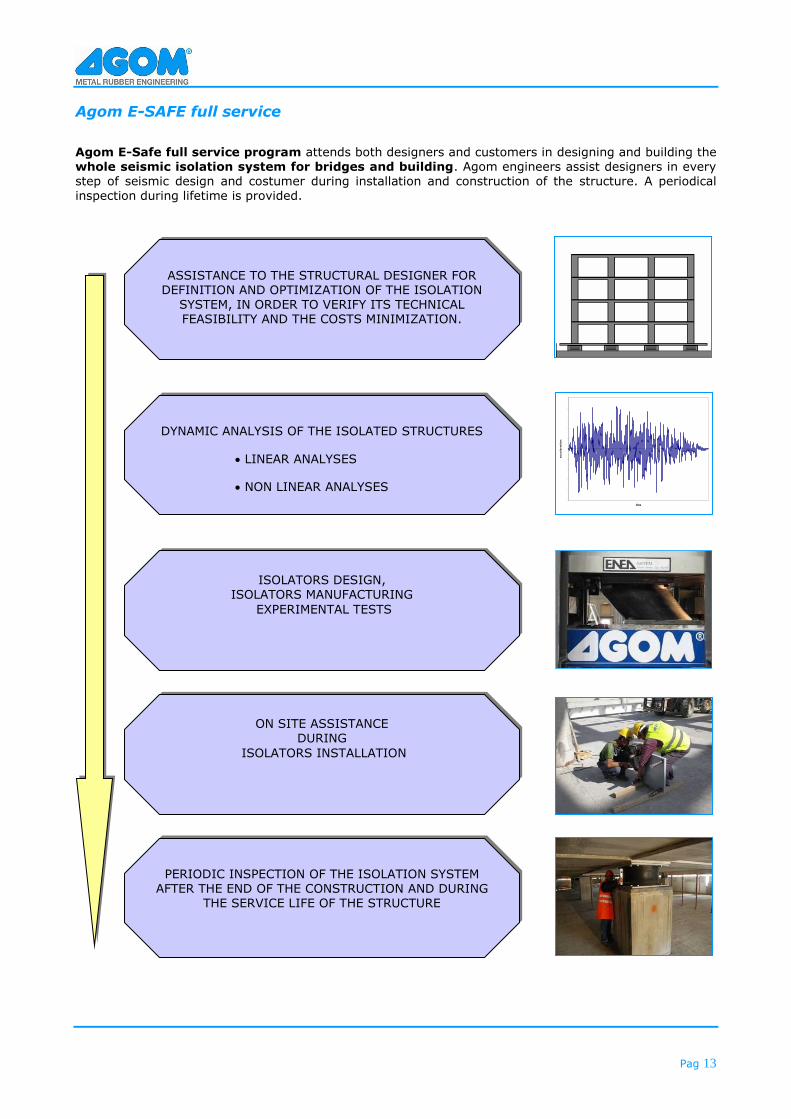
Agom E-Safe full service program attends both designers and customers in designing and building the whole seismic isolation system for bridges and building. Agom engineers assist designers in every step of seismic design and costumer during installation and construction of the structure. A periodical inspection during lifetime is provided.
ASSISTANCE TO THE STRUCTURAL DESIGNER FOR DEFINITION AND OPTIMIZATION OF THE ISOLATION
SYSTEM, IN ORDER TO VERIFY ITS TECHNICAL FEASIBILITY AND THE COSTS MINIMIZATION.
DYNAMIC ANALYSIS OF THE ISOLATED STRUCTURES
• LINEAR ANALYSES
• NON LINEAR ANALYSES
ISOLATORS DESIGN, ISOLATORS MANUFACTURING
EXPERIMENTAL TESTS
ON SITE ASSISTANCE DURING
ISOLATORS INSTALLATION
PERIODIC INSPECTION OF THE ISOLATION SYSTEM AFTER THE END OF THE CONSTRUCTION AND DURING
THE SERVICE LIFE OF THE STRUCTURE
-2.5
-2
-1.5
-1
-0.5
0
0.5
1
1.5
2
2.5
0 5 10 15 20 25
time
ac
ce
lera
tio
n

Pag 14
Agom E-Safe isolators design parameters
Normally the required input parameters that the structural designer has to provide to Agom engineers for device design and constructions are:
Fzd
Maximum vertical load in seismic condition
Minimum vertical load in seismic condition
Ned,max
Ned,min
Kb
DEd
Device equivalent viscous damping
x
Maximum vertical load in static condition
Device horizontal stiffness
Device design displacement (seismic, thermal, irreversible movements)

Pag 15
E-SAFE HDRB standard range
The Agom E-SAFE HDRB isolators are suitable for the seismic isolation of different structures (residential buildings, hospitals, power plant and bridges) and a very wide range of isolators can be manufactured to
reach the target stiffness, displacement, damping according to the structural engineer requirements. In the following pages standard isolators classified at different displacement values are shown, in any case for the seismic isolation system design, Agom can adjust the isolators design parameters to satisfy the specific requirements and assist the structural designer in selection and optimization of the isolation system in order to verify the technical feasibility and the costs minimization.
In the tables of next pages the general design of the E-SAFE HDRB isolators with rubber compounds with different G and damping values (from 10 to 16%) are shown. Adding the lead core, the E-SAFE LRB isolators can be designed in order to reach increased level of
damping of to 30% with a large range of horizontal displacement and vertical load capacity. The isolators listed in the following tables have been designed according to European codes:
- prEN 15129 (for seismic load condition) - EN 1337-3 (for non seismic load condition when the isolators act as normal rubber bearings)
and according to the following criteria:
- The horizontal seismic displacement range is from 100 to 400 mm. The reference displacement has to be considered as the maximum ULS (ultimate limit state) already increased by the safety factors required from the different codes (prNE15129, EN1998.1, EN1998.2)
- The horizontal non seismic displacement used for the static checks is taken as 0.5 times the total rubber thickness
- The stated vertical loads are the maximum that each isolator can support applying the horizontal displacement given by each load condition (seismic or static). The loads have to be considered as the maximum ULS already increased by the safety factors of the different codes (prNE15129, EN1998.1, EN1998.2)
- The considered rotation value is normally 0.005 rad
Since the isolators checks depends on the combination of multiple inputs (load, displacement and rotation) the Agom engineers can assist the structural designer for design optimisation.
For the purposes of this document, the following symbols apply
- HDRB = High damping rubber bearing,
- Dg= rubber diameter
- Tq= total rubber thickness
- Htot= total bearing thickness
- Kb= bearing effective horizontal stiffness (code
prEN15129)
- KV= bearing vertical stiffness (code prEN15129)
- Ned,max= bearing vertical force under the design
seismic action (code prEN15129)
- Fzd = bearing vertical design force (code EN1337-
3)
- L = bearing anchor plate size
- W = bearing weight

Pag 16
MORE THAN 50 YEARS EXPERIENCE DESIGNING AND MANIFACTURING DEVICES FOR CONSTRUCTION, OFFSHORE AND INDUSTRIAL MARKETS
Bridge bearings • Elastomeric Bridge bearings • Pot bearings
• Spherical bearings • Incremental Launching bearings • Horizontal load bearings • Special bearings
Seismic Isolators • High damping rubber bearings • Lead core rubber
bearings • Multilayer rubber bearings • Shock transmitters • Shock absorber • Rubber dampers
Expansion joints • Elastomeric joints • Joints for high movements
• Finger joints • Buried joints • Railway joints
Services • Design • Consulting • On site assistance
• Installations • Tests • Inspection
AGOM INTERNATIONAL SRL Via Mesero, 12 – 20010 Ossona (MI) - Italy
PH.:+39 02 9029111 – FAX:+39 02 9010201 www.agom.it - e-mail: [email protected]
BRIDGES
VIADUCTS
OFFSHORE
INDUSTRY