agrément certificate product sheet-5477ps1i1 · page 6 of 14 figure 4 protective sleeve •...
TRANSCRIPT
Page 1 of 14
Techno Pieux Inc. 1700 Setlakwe Street Thetford Mines Quebec G6G 8B2 Canada Tel: 001 418 332 2139 Fax: 001 877 332 2139 Agrément Certificate e-mail: [email protected] 18/5477 website: www.technometalpost.com Product Sheet 1
TECHNO PIEUX PILING SYSTEM TECHNO METAL POST
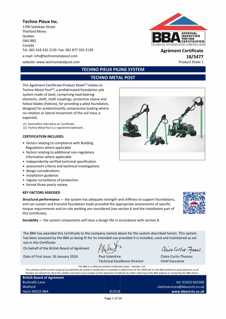
This Agrément Certificate Product Sheet(1) relates to Techno Metal Post(2), a prefabricated foundation pile system made of steel, comprising load bearing elements, shaft, shaft couplings, protective sleeve and helical blades (helices), for providing a piled foundation, designed for predominantly compressive loading where no rotation or lateral movement of the soil mass is expected.
(1) Hereinafter referred to as ‘Certificate’. (2) Techno Metal Post is a registered trademark.
CERTIFICATION INCLUDES:
• factors relating to compliance with Building Regulations where applicable
• factors relating to additional non-regulatory information where applicable
• independently verified technical specification • assessment criteria and technical investigations • design considerations • installation guidance • regular surveillance of production • formal three-yearly review.
KEY FACTORS ASSESSED
Structural performance — the system has adequate strength and stiffness to support foundations, and can sustain and transmit foundation loads provided the appropriate assessments of specific torque requirements and on-site welding are considered (see section 6 and the Installation part of this Certificate).
Durability — the system components will have a design life in accordance with section 8.
The BBA has awarded this Certificate to the company named above for the system described herein. This system has been assessed by the BBA as being fit for its intended use provided it is installed, used and maintained as set out in this Certificate
On behalf of the British Board of Agrément
Date of First issue: 26 January 2018
Paul Valentine Technical Excellence Director
Claire Curtis-Thomas Chief Executive
The BBA is a UKAS accredited certification body – Number 113. The schedule of the current scope of accreditation for product certification is available in pdf format via the UKAS link on the BBA website at www.bbacerts.co.uk Readers are advised to check the validity and latest issue number of this Agrément Certificate by either referring to the BBA website or contacting the BBA direct.
British Board of Agrément Bucknalls Lane Watford Herts WD25 9BA
©2018
tel: 01923 665300
[email protected] www.bbacerts.co.uk

Page 2 of 14
Regulations In the opinion of the BBA, Techno Metal Post, if installed, used and maintained in accordance with this Certificate, can satisfy or contribute to satisfying the relevant requirements of the following Building Regulations (the presence of a UK map indicates that the subject is related to the Building Regulations in the region or regions of the UK depicted):
The Building Regulations 2010 (England and Wales) (as amended)
Requirement: A1 Loading Requirement: A2 Ground movement Requirement: A3 Disproportionate collapse Comment: The system can contribute to providing foundations of adequate strength. See sections
6.1 to 6.3 of this Certificate. Regulation: 7 Materials and workmanship Comment: The system is acceptable. See section 8.2 and the Installation part of this Certificate.
The Building (Scotland) Regulations 2004 (as amended)
Regulation: 8(1) Durability, workmanship and fitness of materials Comment: The system can contribute to a structure satisfying this Regulation. See section 8.2 and
the Installation part of this Certificate. Regulation: 9 Building standards applicable to construction Standard: 1.1(a)(b)(c) Structure Standard: 1.2 Disproportionate collapse Comment: The system can contribute to a structure satisfying this Standard, with reference to
clauses 1.1.1(1)(2) and 1.2.1(1)(2). See sections 6.1 to 6.3 of this Certificate.
(1) Technical Handbook (Domestic). (2) Technical Handbook (Non-Domestic).
The Building Regulations (Northern Ireland) 2012 (as amended)
Regulation: 23 Fitness of materials and workmanship Comment: The system is acceptable. See section 8.2 and the Installation part of this Certificate. Regulation: 30 Stability Regulation: 31 Disproportionate collapse Comment: The system, when incorporated into a suitable structure, can contribute to satisfying
these Regulations. See sections 6.1 to 6.3 of this Certificate.
Construction (Design and Management) Regulations 2015 Construction (Design and Management) Regulations (Northern Ireland) 2016 Information in this Certificate may assist the client, designer (including Principal Designer) and contractor (including Principal Contractor) to address their obligations under these Regulations. See section: 1 Description (1.3) and 3 Delivery and site handling (3.3) of this Certificate.

Page 3 of 14
Additional Information
CE marking The Certificate holder has taken the responsibility of CE marking the system, in accordance with harmonised European Standards BS EN 1090-1 : 2009 and BS EN 1090-2 : 2008.
Technical Specification
1 Description 1.1 Techno Metal Post is a prefabricated foundation system, comprising load bearing elements, shaft, shaft couplings, protective sleeve and helices, designed and made of steel, in accordance with BS EN 1993-5 : 2007, and screwed into the ground, for use to support and transmit foundation loads (see Figure 1). The piles are installed by screwing under the combined action of rotational forces and vertical load using specified machinery (see section 1.3).
Figure 1 Elements of Techno Metal Post
1.2 The system comprises:
• load bearing elements — made of structural steel grade S275 in accordance with BS EN 10025-3 : 2004 for connecting the structure to the supporting shaft. Different load bearing elements are used with different shaft types. These elements can be adjustable or fixed height. For shaft types P1 and P2, described in the next bullet point of this section and shown in Figure 2, the fixed load bearing elements CP, UF or CF can be connected to the shaft and the structure by welding on site. Adjustable load bearing elements CA or UA can also be welded on site to the shaft and the structure. For the other shaft types, bespoke load bearing elements can be welded or bolted on site to the shaft and the structure. The load bearing elements must be designed by an appropriately qualified design engineer in accordance with Eurocode 3 (BS EN 1993-1-1 : 2005, and BS EN 1993-1-8 : 2005 and its UK National Annex)

Page 4 of 14
Figure 2 Load bearing element types
• shaft — consisting of a steel tube of hollow circular cross-section made of steel grade S355NH in accordance with EN 10219-1 : 2006. The diameter and thickness of the shaft vary depending on the loads to be supported. The dimensional details of the shaft types are presented in Table 1. The holes in the top of each shaft are for attachment to the installation rig

Page 5 of 14
Table 1 Shaft cross-section dimensions (1) Shaft type Outside
diameter (mm) Inside diameter
(mm) Wall thickness
(mm)
P1 48.26 40.89 3.68
P2 60.33 52.50 3.91
P3 88.90 77.93 5.49
P3-HD(2) 88.90 73.66 7.62
P4 101.60 90.12 5.74
P4-HD(2) 101.60 85.70 7.95
P5 141.29 128.18 6.55
P6 168.28 154.05 7.11
(1) The standard lengths of the shafts are 1500 mm, 2130 mm and 3200 mm. (2) Heavy Duty.
• shaft couplings — A cylindrical coupler, 76 mm or 89 mm long, made from steel grade S355NH, used to extend the shafts by connecting them together and transferring the actions. The shaft couplings are welded to one end of the shaft at the manufacturing site. The next shaft is welded to the shaft coupling on site. There are two types of shaft couplings: UE for exterior coupling (the shaft is embedded inside the coupling) and UI for interior coupling (the coupling is embedded inside the shaft) (see Figure 3). Couplings are welded to the top of the shaft at the factory. During installation on site the next shaft is positioned on top of the shaft already installed with the help of the coupling, to make location easier. With exterior couplings, the next shaft is embedded inside the coupling and welded at the top. With interior couplers, a central collar on the coupling helps to locate and weld it in the installed shaft. The next shaft is then fitted onto the coupling and welded to it. The welds, in accordance with EN 1090-1 : 2009, have a 6 mm throat dimension and can transfer torsional, compressive, tensile and bending actions between the shafts. They are used where the bearing layer below ground requires the use of extensions, or for above ground level extensions.
Figure 3 Shaft coupling types
• Techno Protective Sleeve — a polyethylene protective sleeve (see Figure 4), used to ensure the shaft is not in contact with the soil. It is generally installed on the shaft located in the superficial (e.g. 0 to 2 m) layers of soil that may be affected by ground movements, due to, for example, freeze/thaw groundwater movements, clay swelling and shrinking, or any negative friction conduction

Page 6 of 14
Figure 4 Protective sleeve
• helices — helical blades of steel grade S275, manufactured in accordance with BS EN 10025-3 : 2004. They are factory-welded to the shaft in accordance with BS EN ISO 3834-3 : 2005. The diameter of the helices can be 152 mm, 203 mm, 254 mm, 305 mm, 356 mm, 406 mm, 457 mm, 508 mm or 610 mm, with 9 mm thick blades for shaft types P1 and P2, and 12.5 mm thick blades for other larger shafts (see Table 1). The pitch of the helix is 76 mm. A Techno Metal Post is generally supplied with one helix at the base of the shaft. For specific ground conditions or applications (see Section 6.4), the system can be supplied with two or more helices, distributed along the shaft (see Figure 5). The number and diameter of the helices are determined depending on the design load and nature of the soil in which the helix is embedded.
Figure 5 Various helices configurations for Techno Metal Post
1.3 The characteristics of the machinery developed by Techno Pieux Inc., which must be used to install the piles (outside the scope of this Certificate), are provided in Table 2. The track pressure for the machinery should be checked in accordance with BRE BR 470, Working platforms for tracked plants: good practice design to the design, installation, maintenance and repair of ground supported working platforms, prior to commencing the installation.

Page 7 of 14
Table 2 Installation equipment developed by Techno Pieux Inc Characteristic Machinery
R2D EM-1 ET-1
Dimensions (all in mm) 2500*760*1500 2362*1219*1676 4267*1727*2133
Mass (kg) 750 2025 4037
Maximum mast height (mm) 3400 3683 4572
Minimum required lateral clearance for installation (mm) 178 203 229
Maximum service bearing capacity under compression per pile installed (kN)
115 150 225
Ultimate bearing capacity under compression per pile installed (kN)
161 210 315
1.4 R2D, EM-1 and ET-1 installation equipment, described in Figure 6, are CE marked in accordance with Machinery Directive 2006-42-EC. The method used for calibration of the torque measurement devices has been evaluated by the BBA. The calibration procedure involves installing a certified torque monitor on the driving head of the installation equipment and inserting it onto a dynamic brake anchored to a rigid support. The screwing function is simply activated and the braking force is adjusted on the dynamic brake in order to obtain a specific pressure on the manometer. At each of the specified pressures, the screwing torque is measured.
Figure 6 Machines for the installation of the Techno Metal Post (outside the scope of this Certificate)

Page 8 of 14
2 Manufacture 2.1 Raw materials used in the manufacture of the system are obtained from the Certificate holder’s approved suppliers, to an agreed specification and in accordance with the company’s documented quality control procedures. 2.2 The shaft and helices are assembled by welding at the factory. When requested, the shafts, helices and couplers are hot dip galvanized with a minimum coating of 530g/m². 2.3 As part of the assessment and ongoing surveillance of product quality, the BBA has:
• agreed with the manufacturer the quality control procedures and product testing to be undertaken
• assessed and agreed the quality control operated over batches of incoming materials
• monitored the production process and verified that it is in accordance with the documented process
• evaluated the process for management of nonconformities
• checked that equipment has been properly tested and calibrated
• undertaken to carry out the above measures on a regular basis through a surveillance process, to verify that the specifications and quality control operated by the manufacturer are being maintained.
2.4 The management system of the manufacturer, has been assessed and registered as meeting the requirements of EN ISO 9001 : 2015 by National Quality Assurance (Certificate 17081).
3 Delivery and site handling 3.1 The system components are delivered to site by the Certificate holder’s operatives and/or by fully-trained transport sub-contractors in accordance with the Certificate holder’s instructions. 3.2 The shafts are crated in steel racking systems. 3.3 The weight of the shafts may be in excess of 180 kg. Due care must be taken while handling the system.
Assessment and Technical Investigations The following is a summary of the assessment and technical investigations carried out on Techno Metal Post.
Design Considerations
4 Use 4.1 Techno Metal Post is satisfactory for use as a piled foundation, by screwing the system to the desired depth, provided that the design for each project is verified by the Certificate holder and the system is installed by qualified installers. The system is designed to resist static or dynamic axial (compressive and/or tensile) and shear actions. 4.2 The system components are for use as a complete foundation system or part of a foundation system, incorporating pile caps or ground beams, the design of which is outside the scope of this Certificate. 4.3 The system, when correctly installed and designed, is capable of transmitting structural loading safely to the loadbearing soil. 4.4 The system is installed to the required depth or a design torque using specific installation equipment developed by Techno Pieux Inc. Assessment of the suitability of the system for use in any particular ground conditions should be based on the results of an adequate site investigation, following the recommendations of BS 5930 : 2015. Full consideration must be given to various factors which can affect the assumed performance. The limitations for use of the piles are set out within this Certificate and the user should be aware of these limitations.

Page 9 of 14
4.5 The overall length of pile is dependent on soil conditions, applied working load, working conditions, design factor of safety and limiting criteria specified by the overall design. 4.6 Information provided in respect of ground conditions can vary on a project-specific basis and the system must be designed by an appropriately qualified pile design engineer on behalf of Techno Pieux Inc. with reference to BS EN 1997-1 : 2004 and its UK National Annex. 4.7 The pile layout and design should be in accordance with the requirements of Eurocode7 (BS EN 1997-1 : 2004 and its UK National Annex), using the safe working loads provided by the Certificate holder. The Certificate holder’s Installation Manual gives further guidance on the extent of site investigation required and the pile testing regime to be adopted. Site investigations should follow the recommendations given in BS 5930 : 2015. Information about structural design and geotechnical performance of the system is provided in Sections 6.10 to 6.14. Site investigations must:
• confirm the depth to each soil stratum, water table and their variation;
• indicate the presence of caves, buried works, boulders, rocks and stones larger than 50 mm;
• characterise homogeneity or heterogeneity and the mechanical properties of the soil to and beyond the stratum with adequate bearing capacity;
• Identify any layers of soil with shrinkage, heave or liquefaction potential, hardened sediments, aggressiveness. 4.8 Full consideration must be given to the requirements of pile design defined in BS EN 1993-1-1 : 2005, BS EN 1993-5 : 2007 and BS EN 1997-1 : 2004 and their UK National Annexes. 4.9 The general principles recommended in BS EN 12699 : 2015 must be considered for the execution of screw piles. 4.10 Full consideration must be given to the particular ground conditions when assessing the suitability of the system. The following factors apply:
• made-ground containing obstructions — where made-ground containing large or hard obstructions is encountered they should either be removed prior to piling or alternative pile positions determined.
• where large boulders or artificial hard obstructions (eg concrete) are present that may cause lateral displacement of the lower part of the pile during installation, they should either be removed prior to piling or alternative pile positions must be identified. Where this is not possible, an alternative pile system should be considered by a suitably qualified and experienced individual
• where steeply sloping hard strata exist that may cause lateral displacement of the lower part of the pile resulting in pile failure, an alternative pile system should be considered by a suitably qualified and experienced individual
• ground containing voids — where voids are encountered, the pile should be relocated if possible, or an alternative pile system adopted
4.11 The minimum spacing between the piles should be three times the diameter of the largest helix.
5 Practicability of installation Techno Metal Post is designed to be installed by competent and certified trained installers, experienced and qualified with this type of system, using the specific installation equipment designed by Techno Pieux Inc. The Certificate holder provides a specific training course for installers.
6 Structural performance General
6.1 Techno Metal Post has adequate strength and stiffness to sustain the loads to which it is subjected during normal handling, transportation and installation. The BBA have analysed a range of typical designs and confirmed that the design methodology is appropriate, the section properties and resistance are accurately determined in accordance with BS EN 1993-1-1 : 2005, BS EN 1993-5 : 2007, BS EN 1997-1 : 2004, BS EN 1998-1 : 2004 and BS EN 1998-5 : 2004 and their UK National Annexes, and that an adequate range of loading cases, together with relevant load and material factors, are considered.

Page 10 of 14
6.2 The system can withstand the dynamic loadings likely to occur during installation. 6.3 The piles must be designed by a chartered civil or structural engineer on behalf of Techno Pieux Inc. When installed to the required depth and designed screwing torque, the pile itself is capable of carrying the working loads specified by the design engineer. In the event that the agreed installation torque is achieved before the design depth, the design must be reviewed by the pile design engineer to establish acceptability of the installation depth.
6.4 The system can be considered as an end bearing element and the skin friction of the shaft is negligible. The load bearing capacity of the system is principally provided by the helix, both in reaction to compressive and tensile loads. Under tensile loads the helix anchors the pile in the overburden soil stratum. To increase the load bearing capacity with low bearing resistance soil conditions, to enable the use of comparatively smaller helices or to reduce the settlement of the system, it is possible to use multiple helices on one shaft. This will distribute the loads transferred to the soil at multiple depths. The distance between the helices must be at least 3 times the largest diameter helix in order to allow the bearing load distribution with minimum stress overlap. However, the overall capacity cannot exceed the structural strength of the pile to pure compressive or tensile loads as given in Table 1, taking in to consideration the reduction of the cross-section due to corrosion to BS EN 1993-5 : 2007 and its UK National Annex. 6.5 The installation equipment continuously records the installation torque required for screwing the piles. This depends on the soil type and strength at the helix depth, and the geometrical specifications of the helix. The torque is directly proportional to the axial load bearing capacity of the pile. The correlation factor for axial load bearing capacity of the pile to the screwing torque is empirically developed by tests performed by Techno Pieux Inc. and formulas based on test reports publicly available via the Certificate holder’s website. In case the soil condition doesn’t comply with the range of soils tested previously or for sensitive installations requiring determination of precise load bearing capacity, a site-specific correlation factor between the installation torque and the load bearing capacity must be developed through testing. 6.6 When required, static load testing using anchoring piles must be used to validate the bearing capacity of the piles. The responsibility for the number of piles to be tested, correlation factors and the factor of safety to be applied remains with the qualified pile design engineer on behalf of Techno Pieux Inc. with reference to the Tables A.NA.9, A.NA.10, A.NA.11 and A.NA.6 of the UK National Annex to BS EN 1997-1 : 2004, and the NHBC Design Guide NF 21, Efficient Design of Piled Foundations for Low Rise Housing. 6.7 There is no established relation between the lateral load capacity of the piles and the screwing torque. If lateral load bearing capacity is a design requirement, a site-specific test must be carried out to establish that the pile can resist the design loads. 6.8 If the structure and foundation are to be designed for seismic actions, the piles must be designed to BS EN 1998-1 : 2004 and BS EN 1998-5 : 2004, and their UK National Annexes. 6.9 Techno Metal Post, when correctly installed, will withstand the effects of design actions without undue deterioration in strength or stiffness for the life of a structure, when designed in accordance with BS EN 1993-1-1 : 2005, BS EN 1993-5 : 2007 and their UK National Annexes. Structural design 6.10 Based on the aggressiveness of the soil and the corrosion protection method used, a thickness reduction of the shaft wall due to corrosion during the life time of the pile is calculated. The cross sectional properties of the shaft are calculated based on the reduced cross section (considering the reduced thickness of the shaft). The classification of cross section based on section 5.5 of BS EN 1993-1-1 : 2005 and the partial factors based on section 5.1.1 of BS EN 1993-5 : 2007 are calculated. 6.11 Structural resistance of the system to axial actions, shear and bending moments and their combined effects are calculated based on section 6.2 of BS EN 1993-1-1 : 2005. 6.12 Checking against buckling is essential for “slender piles passing through water or thick deposit of extremely low strength fine soil”, based on Note (4) in section 7.8 of BS EN 1997-1: 2005. Note (5) in the same section explains that “normally a check for buckling is not required when the piles are contained with a characteristic shear strength, Cu, that exceeds 10 kPa”. Therefore, if required, a stability check under ultimate limit state must be done in accordance with

Page 11 of 14
section 6.3 of BS EN 1993-1-1 : 2005. The buckling length is determined in accordance with section 5.3.3 of BS EN 1993-5 : 2007 for the zone of the pile not laterally supported by soil with characteristic shear strength, Cu, that exceeds 10 kPa. 6.13 To check the serviceability limit state the three criteria, vertical deflection, horizontal deflection and dynamic performance in accordance with section 7.2 of BS EN 1993-1-1 : 2005 must be considered. The acceptance criteria must be determined based on the serviceability limitations of the supported structure. 6.14 To validate if the design load capacity is developed when the design installation depth is reached, the driving torque is measured and based on the correlation factor explained in Section 6.5, the developed axial load bearing capacity is calculated. If this capacity exceeds the design load the installation is satisfactory.
7 Maintenance Once the system is installed, maintenance is not required. However, it is important that the piles are checked for suitability prior to installation.
8 Durability 8.1 Resistance to the effects of corrosion is achieved through the specification of appropriate steel section to ensure that the wall thickness remains adequate for the life of the structure. If additional protection is required the steel may be hot dip galvanized or provided with cathodic protection.
8.2 For durability greater than or equal to 50 years, the Certificate holder systematically uses an electrochemical technique (Techno Protection) which is a cathodic protection principle adapted for Techno Metal Posts that may protect simple or more complex installations.
Installation
9 General 9.1 Following delivery, and prior to installation, the piles should be checked by the pile installers for damage, in accordance with the Certificate holder’s instructions. 9.2 Provided the ground conditions are suitable and as predicted from the site investigation, and the method of installation is as detailed in this Certificate, piles can be installed without undue difficulty. 9.3 The pile elements are supplied for installation by trained and approved installers using specific installation equipment designed by Techno Pieux Inc. in strict accordance with the Certificate holder’s Installation Manual, BS EN 1997-1 : 2004 and its UK National Annex, and this Certificate.
10 Procedure Installation 10.1 The installation equipment is located where the pile is being installed. 10.2 The shaft with the helix is mounted on the installation equipment. The pile toe is located accurately by the certified installer and the pile head into the driving head of the equipment. The installation equipment is precisely located such that the pile toe points to the correct installation location. 10.3 Torsion is applied to the pile to screw it into the ground. Once the first pile is screwed, the screwed shaft is dislodged from the driving head of the installation equipment. When the sleeve is required, it is installed on the shaft before it is lodged on the driving head and screwed.

Page 12 of 14
Jointing 10.4 If the design length of the pile requires installation of multi shafts, a shaft coupling is embedded into the first shaft and welded. Another shaft element is connected to the driving head and lifted and carefully guided onto the UE or UI shaft coupling and welded. 10.5 If the pile is to be extended above ground level, the shaft elements are connected by UE or UI shaft couplings with or without welding. 10.6 Screwing of the shafts continues until the design installation depth is reached or the applied torque proves the design load capacity is reached. 10.7 The load bearing element (connection with the supported structure) is welded to the top end of the pile.
Technical Investigations
11 Investigations 11.1 The manufacturing process was evaluated, including the methods adopted for quality control, and the quality and composition of the materials used. 11.2 An examination was made of technical data relating to:
• effect of corrosion of the steel sections
• existing data relating to the durability when used within the scope of this Certificate. 11.3 A site visit was carried out to assess the practicability of installation. 11.4 An examination was made of the Certificate holder’s Installation Manual. 11.5 An examination was made of pile penetration log data relating to sites where piles have been successfully installed and tested by static or dynamic pile testing techniques. 11.6 The assessment of the system was made in relation to BS EN 1997-1 : 2004 and BS EN 1993-1-1 : 2004. 11.7 An assessment of axial load test reports was carried out on the system as follows: • test piles installed in different types of soil were tested and subject to working loads. Deflections were measured
and the correlation between deflection and load bearing capacity were approved • test piles installed in different types of soil were tested and subject to ultimate loads. Deflections were measured
and the correlation between deflection and load bearing capacity were approved • helix capacity tests were performed on 9 helices of 3 different diameters and the mode of failure was either weld
shear or local buckling of the shaft. No failure of the helix was recorded.

Page 13 of 14
Bibliography BRE Report BR 470 : 2004 Working platforms for tracked plant — good practice guide to the design, installation, maintenance and repair of ground-supported working platforms BS 5930 : 2015 Code of practice for ground investigations BS EN 1090-1 : 2009 + A1 : 2011 Execution of steel structures and aluminium structures. — Requirements for conformity assessment of structural components BS EN 1090-2 : 2008 + A1 : 2011 Execution of steel structures and aluminium structures — Technical requirements for steel structures BS EN 1993-1-1 : 2004 + A1 : 2014 Eurocode 3 — Design of steel structures — General rules and rules for buildings NA + A1 : 2014 to BS EN 1993-1-1 : 2004 + A1 : 2014 UK National Annex to Eurocode 3 — Design of steel structures — General rules and rules for buildings BS EN 1993-1-8 : 2005 Eurocode 3 — Design of steel structures — Design of joints NA to BS EN 1993-1-8 : 2005 UK National Annex to Eurocode 3 — Design of steel structures — Design of joints BS EN 1993-5 : 2007 Eurocode 3 — Design of steel structures — Piling NA + A1 : 2012 to BS EN 1993-5 : 2007 UK National Annex to Eurocode 3 — Design of steel structures — Piling BS EN 1997-1 : 2004 + A1 : 2013 Eurocode 7 : Geotechnical design — General rules NA + A1 : 2014 to BS EN 1997-1 : 2004 + A1 : 2013 UK National Annex to Eurocode 7 : Geotechnical design — General rules BS EN 1998-1 : 2004 + A1 : 2013 Eurocode 8 — Design of structures for earthquake resistance — General rules, seismic actions and rules for buildings NA to BS EN 1998-1 : 2004 UK National Annex to Eurocode 8 — Design of structures for earthquake resistance — General rules, seismic actions and rules for buildings BS EN 1998-5 : 2004 Eurocode 8 — Design of structures for earthquake resistance — Foundations, retaining structures and geotechnical aspects NA to BS EN 1998-5 : 2004 UK National Annex to Eurocode 8 — Design of structures for earthquake resistance — Foundations, retaining structures and geotechnical aspects BS EN 10025-3 : 2004 Hot rolled products of structural steels — Technical delivery conditions for normalized/normalized rolled weldable fine grain structural steels BS EN 12699 : 2015 Execution of special geotechnical work — Displacement piles BS EN ISO 3834-3 : 2005 Quality requirements for fusion welding of metallic materials — Documents with which it is necessary to conform to claim conformity to the quality requirements of ISO 3834-2, ISO 3834-32 or ISO 3834-4 EN 10219-1 : 2006 Cold formed welded structural hollow sections of non-alloy and fine grain steels — Technical delivery requirements EN ISO 9001 : 2015 Quality management systems — Requirements

Page 14 of 14
Conditions of Certification
12 Conditions 12.1 This Certificate:
• relates only to the product/system that is named and described on the front page
• is issued only to the company, firm, organisation or person named on the front page – no other company, firm, organisation or person may hold claim that this Certificate has been issued to them
• is valid only within the UK
• has to be read, considered and used as a whole document – it may be misleading and will be incomplete to be selective
• is copyright of the BBA
• is subject to English Law. 12.2 Publications, documents, specifications, legislation, regulations, standards and the like referenced in this Certificate are those that were current and/or deemed relevant by the BBA at the date of issue or reissue of this Certificate. 12.3 This Certificate will remain valid for an unlimited period provided that the product/system and its manufacture and/or fabrication, including all related and relevant parts and processes thereof:
• are maintained at or above the levels which have been assessed and found to be satisfactory by the BBA
• continue to be checked as and when deemed appropriate by the BBA under arrangements that it will determine
• are reviewed by the BBA as and when it considers appropriate. 12.4 The BBA has used due skill, care and diligence in preparing this Certificate, but no warranty is provided. 12.5 In issuing this Certificate the BBA is not responsible and is excluded from any liability to any company, firm, organisation or person, for any matters arising directly or indirectly from:
• the presence or absence of any patent, intellectual property or similar rights subsisting in the product/system or any other product/system
• the right of the Certificate holder to manufacture, supply, install, maintain or market the product/system
• actual installations of the product/system, including their nature, design, methods, performance, workmanship and maintenance
• any works and constructions in which the product/system is installed, including their nature, design, methods, performance, workmanship and maintenance
• any loss or damage, including personal injury, howsoever caused by the product/system, including its manufacture, supply, installation, use, maintenance and removal
• any claims by the manufacturer relating to CE marking. 12.6 Any information relating to the manufacture, supply, installation, use, maintenance and removal of this product/system which is contained or referred to in this Certificate is the minimum required to be met when the product/system is manufactured, supplied, installed, used, maintained and removed. It does not purport in any way to restate the requirements of the Health and Safety at Work etc. Act 1974, or of any other statutory, common law or other duty which may exist at the date of issue or reissue of this Certificate; nor is conformity with such information to be taken as satisfying the requirements of the 1974 Act or of any statutory, common law or other duty of care.
British Board of Agrément Bucknalls Lane Watford Herts WD25 9BA
©2018
tel: 01923 665300
[email protected] www.bbacerts.co.uk