agri-inject, inc. apcagri-inject.com/wp-content/uploads/2012/12/microtube_surefireapc...agri-inject,...
TRANSCRIPT

Agri-Inject, Inc.
APC Automatic Pump Control
for DC Pumps
Agri-Inject, Inc.
5500 E. Hwy 34 P.O. Box 437
Yuma, Colorado 80759 Phone: 970-848-5336 800-446-5328
Fax: 970-848-5338 888-846-5328 E-mail: [email protected]
Web Site: http://www.agri-inject.com

APC AUTOMATIC PUMP CONTROL
Reference Manual
The Automatic Pump Control system controls the application rates of liquid chemicals or fertilizer by varying the RPM of 12 VDC pump (s). No servo valve is required with this system. The APC can control either a single pump system or, if additional flow range or capacity is needed, it will control a dual pump system. If a dual control pump system is used, the pumps must be plumbed in parallel, with appropriate check valves to prevent flow back or bypass. The APC is programmed to turn on the secondary pump only when the application when the application rate requires more flow than the primary pump can deliver. NOTE: The APC is factory-programmed for dual-pump operation; to use with a single pump, follow the instructions on page 16 of this manual. The APC has been designed for easy installation and operation. However, since each installation will vary depending on your equipment, please take the time to familiarize yourself with this manual and the actual components before beginning. Following the procedures described in this manual will ensure proper performance and help avoid problems or questions once you are in the field. This manual is written for the Automatic Control System. Please read this manual carefully and follow the instructions as they apply to your usage. If you do encounter a problem that cannot be corrected by reviewing this manual, consult your dealer or distributor, or contact an Agri-Inject, Inc. technician for assistance.
Agri-Inject, Inc.
5500 E. Hwy 34 P.O. Box 437
Yuma, Colorado 80759
Phone: 970-848-5336 800-446-5328
Fax: 970-848-5338 888-846-5328
E-mail: [email protected]
Web Site: http://www.agri-inject.com
2

Table of Contents
3
table of Contents .......................................................................................................................................................................3-4Component Parts and Assembly Hardware .........................................................................................................................5DC Pump Control overview Diagram.....................................................................................................................................6DC Pump Control Wiring Diagram ..........................................................................................................................................7Installation ................................................................................................................................................................................. 8-12 required tools ..............................................................................................................................................................................................8 mounting the display console ...............................................................................................................................................................8 Electrical installation .................................................................................................................................................................................8 Connecting Power and Ground ....................................................................................................................................................8 Pump Connections ............................................................................................................................................................................8 other Connections ............................................................................................................................................................................8 mounting and Plumbing Flowmeter ..................................................................................................................................................9 Installing Flow Sensor Cable ..................................................................................................................................................................9 Speed Sensor Instalation ................................................................................................................................................................10-12 magnets ........................................................................................................................................................................................10-11 Attaching the Speed Sensor .......................................................................................................................................................11 Connecting the Speed Sensor Cable .......................................................................................................................................12 Speed Sensor options ..................................................................................................................................................................12 DC Pump Control Console Functions .................................................................................................................................. 13Calibration ...............................................................................................................................................................................14-18 English or metric ......................................................................................................................................................................................14 Entering Calibration Values ..................................................................................................................................................................14 Flow Cal, tank Volume, Adjust rate, target rate, Width Cal, 1 Pump/2 Pump, Speed Cal .............................15-16 test Speed ..................................................................................................................................................................................................16 Exiting Calibration ...................................................................................................................................................................................16 Factory-loaded Calibration Values ...................................................................................................................................................16 radar or GPS Speed Sensor Calibration table ..............................................................................................................................17 "Special" Calibration .........................................................................................................................................................................17-18 tank Alarm Set Point, Auto Delay time, units, Valve response Speed .......................................................................18
operation....... ..........................................................................................................................................................................19-21 operation Console Power/System on/off, Display, run/Hold Switch, Auto/man Button, "+" and "-" Buttons, on-the-Go "Delta" rate Adjustments (Adjust rate), Boom Switches, Warning Device, rotary Switch ...........................................................................................................................................19-20 Data Description rate, tank, Volume/minute, Volume, Area, Distance, Area/Hour, Speed ......................................................................20 resetting System Counters ..................................................................................................................................................................21 Pre-Field System Checkout ..................................................................................................................................................................22

Table of Contents, continued
4
troubleshooting ....................................................................................................................................................................23-26 messages/Warnings ................................................................................................................................................................................24 Console appears dead ...........................................................................................................................................................................24 Speed is always zero or erratic ...........................................................................................................................................................24 Area count is inaccurate........................................................................................................................................................................24 Distance count is inaccurate ...............................................................................................................................................................24 no readout of gallons (liters) or gallons per minute (liters per minute) .............................................................................24 total liquid used is inaccurate ............................................................................................................................................................24 6553.5 message ........................................................................................................................................................................................24 Console is erratic in operation ............................................................................................................................................................24 Displayed measurements do not make sense ..............................................................................................................................24 Display reads “oFl” ..................................................................................................................................................................................24 Checking individual components ...............................................................................................................................................25-26 Console ...............................................................................................................................................................................................25 Harness ...............................................................................................................................................................................................25 Electrical Interference ...................................................................................................................................................................25 Power ...................................................................................................................................................................................................25 Accessory Power .............................................................................................................................................................................25 magnetic Hall-Effect Speed and Flow Sensors ....................................................................................................................25 Vansco radar Speed Sensor ........................................................................................................................................................25 Console Inputs .................................................................................................................................................................................25 Speed Input ...............................................................................................................................................................................25 Flow Input ..................................................................................................................................................................................25 Flowmeter ..................................................................................................................................................................................25 Electric Boom Values ..............................................................................................................................................................25 Plumbing ....................................................................................................................................................................................25
Plumbing Guidelines ................................................................................................................................................................. 26 General ........................................................................................................................................................................................................26 Pump inlet ..................................................................................................................................................................................................26 Flowmeter ..................................................................................................................................................................................................26 Pump ............................................................................................................................................................................................................26 Valve Purpose and Adjustments ........................................................................................................................................................26 Appendices ..............................................................................................................................................................................27-36 Appendix A: optional Speed Sensor mounting Installation ............................................................................................28-29 Appendix B: Calibrating if using a magnetic Speed Sensor ...................................................................................................30 Appendix C: Fine tuning Speed/Distance Calibration Value .................................................................................................31 Appendix D: Fine tuning Flowmeter Calibration Value ...........................................................................................................32 Appendix E: Flowmeter Assembly ...................................................................................................................................................33 Appendix F: radar "Y" Adapter Cables ...........................................................................................................................................34 Appendix G: Conversion Chart ..........................................................................................................................................................35 Appendix H: replacement Parts list ...............................................................................................................................................36
Warranty

Component Parts and Assembly HardwareBefore beginning installation, check the carton contents for the following items:
5
Instructions terminal KitP/n 13270
reference manualP/n 17487
E D C B A A
B
C
D
E
20' Power/Boom HarnessP/n 14600
motor CablesP/n 14586 (10') or
P/n 14587 (30')
Speed/Flow/run-Hold CableP/n 14582 (10') or
P/n 14583 (30')
14" nylon Cable ties P/n 12910
Console mount KitP/n 13774
Fm750GFn Flowmeter
Kit P/n 01501
Fm500 Flowmeter
Kit P/n 01500
DC Pump ControlP/n 17485
DC P umP Control
Automatic rate Control
for DC Pumps
rEFErEnCE mAn uAl
15' motor Extension Cable (2)
P/n 14589
OR
15' 10-Pin m/P Cable with local Speed Access P/n 14607
20' 5-Pin m/P ExtensionCable P/n 14588
A B C
5' Hall-effect Flow Sensor Cable with threaded sensor
P/n 13096

DC Pum
p Control Diagram
6
(optional)
(optional)
+12 VDC Aux. Pow
er
+12 VDC (red)
run
/Ho
lD

P/n14607
YEllo
WtIE
P/n14588
180"ext.
P/n14584
,120"P/n
14585,360"
P/n14582,
120"P/n
14583,360"
P/n14586,
120"P/n
14587,360"
P/n14589
180"ext.
DC Pump Control Diagram
P/n 14600
optional
optional
7
DC Pump Control+12 VD
C
Gn
D

8
InstallationMounting the Display ConsoleSelect a mounting location which seems most workable, and that best fits your needs. It should be con ve nient to reach and high ly vis i ble to the op er a tor. DO NOT IN STALL IN A PO SI TION THAT OB STRUCTS THE VIEW OF THE ROAD OR WORK AREA. Whenever pos si ble, avoid lo ca tions that expose the con sole to direct sun light, high tem per a ture, strong chemicals or rain.
Place the mounting bracket in the selected lo ca tion, mark holes, drill 1/4" (7mm) holes and mount bracket with bolts, lock wash ers and nuts pro vid ed. (If bolts are not practical, use self-tapping screws.) See illustration 1.
Insert the console in the “u” bracket and install the console knobs through the bracket, placing a rubber washer over the threaded stud. Position console to proper viewing angle and tighten the knobs securely.
Illustration 1
Connecting Power and Groundthe DC Pump Control must be connected to a 12-volt DC elec tri cal system. Power is connected directly to the battery. the DC Pump Control has an on/oFF switch on the console to turn the power off when the system is not being used.
locate the power cable harness and connect to the mating connector on the console. route the power cable from the console to the battery. Cut off excess length. In routing cable to battery, avoid ar eas where the ca ble may be subjected to abra sion or ex ces sive heat. Install the in-line fuse provided with the kit on the red wire, as illustrated, to protect the circuit. Connect the orAnGE wire (hot) to the positive battery terminal. At tach the BlACK wire (ground) to a screw or bolt on the equipment frame. See il lus tra tion 2. Be sure there is good metal-to-metal con tact.
Your DC Pump Control is equipped with an ad vanced elec-tronic mem o ry which does not re quire a con stant supply of pow er to re tain daily totals or calibration val ues. the advantage with this type of memory is that it conserves battery power and will not dis charge the vehicle’s battery when equipment is not in use.
NOTE: If connecting to two six-volt batteries in series, the connections must be made per illustration 3, to supply 12 volts to the control system.
Pump ConnectionsSeparate cables are provided to connect pump 1 and pump 2 (refer to overview Diagram, page 6). notE: if only one pump is used, it muSt be connected to the pump cable with rED cable tie, identified as "m1" on the diagram.
Other Connectionsto connect to speed, flow and run/hold sensors, or optional boom valves, refer to the overview Diagram.
Electrical Installation
Ground
orange
red
20-amp in-line fuse required.Hot
(orange)
Illustration 2
Tools Needed to Install DC Pump` Control:
Screwdrivers PliersSet of Wrenches Wire CutterElectric Drill and Bits Center Punch12-Volt test light Hammer
Ground(black)
Hot (WHItE)
20-amp in-line fuse required.
Ground (BlACK)
NOTE: For negative ground systems only.Ground
Illustration 3
NOTE: For negative ground systems only.
Power/GroundP/n 14600

C B
A A B
C
9
Mounting and Plumbing Flowmeter
the Flowmeter must be installed in the boom supply line after any strainers, return lines, or valves, but before the boom shut-off valves. Se cure ly mount flow-me ter (hardware not supplied) in a vertical position in an area away from in tense vibration. Do not install flowmeter closer than 12" to the boom shut-off valves. (the flow me ter may need periodic cleaning, so it should be easy to remove.) the flow meter is a bi-directional meter (exception: Polmac’s 1 1/2"–3"). Liquid can flow in either direction, but the flow should be from bottom to top, particularly where flow rates are low. This prevents air in the meter and partial flow which would cause errors. make con nec tions us ing 1/2" fit tings without the use of reducers, elbows or sharp bends for a minimum of six inches (15 cm) either side of meter. See illustration 4.
Save plastic plugs to protect flowmeter during storage.
Hose clamps*
“l” bracket*
Flow
*not supplied
Illustration 4
1/2" nPt male fitting*
Sprayer line*to booms Hose clamp*
Hose clamp*
With the flowmeter in place, install the flow sensor cable (GrEEn body).
Screw all the way in finger tight; back off 1/3 turn. tight en 3/8" jam nut to lock sen sor in place.
uncoil flow sensor cable and carefully route it to meet the main harness flow connector marked with GrEEn tie. Align connectors and press firmly together until locking tab clicks into place. Secure cable with ties provided. See illustration 5a.
IMPORTANT: See pages 6 & 7 for complete wiring diagrams.
Installing Flow Sensor Cable
Connect flow sensor cable to green-tie console cable.
Flow sensorcable connector
main harness flow connector
Illustration 5
GrEEn tie
Sensor
locknut
A B C Green body
5' Hall-effect Flow Sensor Cable with threaded sensor
and male connector (P/n 13096)
Illustration 5a
NOTE: If you purchased the low-Flow version of the DC Pump Control System, refer to Appendix F for flowmeter installation.

10
Please read the following information about magnet spacing and polarity.
the number of magnets that must be used depends on the size of your tire and where you mount the sensor. on tractor or implement wheels the general rule of thumb is one magnet for each wheel bolt (minimum of two, and always an even number). For drive shafts or small wheels (AtV’s), two magnets are usually adequate.
Some installations may require that more than two magnets be installed. to determine the number of magnets required, measure the distance traveled of one revolution of the sensor equipped wheel in inches (centimeters).
See the following tables to find the minimum number of magnets required (always an even number) -
the magnets provided by micro-trak are marked with a punched dashed line on the SoutH pole side of the magnet. See illustration 6a.
Always use an even number of magnets, and always alternate the polarities of the magnets as you go around the wheel hub or drive shaft.
to install, mount the first magnet with the SoutH pole side (dashed line) facing toward the hub or shaft. mount the second magnet with the nortH pole side facing toward the hub or shaft. See illustration 6B.
For proper operation, the magnets must be evenly spaced around the wheel or drive shaft. the magnets must be at least 1” apart. See illustration 6c.
Magnets
Illustration 6A
Please Note: If you have purchased an Astro GPS Speed Sensor, a Vansco radar or other radar or GPS speed sensor, disregard the following section on magnetic speed sensors and install the Astro, the Vansco or other radar as described in the instructions included with the unit. You may need an adapter cable to connect to radar or GPS Speed Sensor, see Appendix G.
Speed Sensor Installation
locations where the sensor may be installed:
1. non-driven wheel on tractor, vehicle or implement. this is less susceptible to errors resulting from wheel slip.
Installation Note: the harness (P/n 14607) provides either local or remote connection for the speed sensor. For speed sensor installations on implements, add 3-pin extension cables as required.
locate the following parts:
Speed sensor cable (Green body)mounting “l” bracketmagnetsCable ties
Illustration 6B
north South
north
north
South
South
1
2
34
5
6
test magnet should al ter nate ly attract and repel.
S
n
English or Turf (inches)
Wheel Circumference: 40 80 120 160 200
number of magnets: 2 4 6 8 10
Metric (cm)
Wheel Circumference: 100 200 300 400 500
number of magnets: 2 4 6 8 10
2. tractor, vehicle or planter drive shaft. this type of mounting is recommended for trucks, four-wheel drive tractors or other equipment that has poor or no access to a non-driven wheel. See Appendix A for magnetic speed sensor installation details for various types of wheels or drive shaft.

Attaching the Speed Sensorthe magnets are attached to a wheel hub or drive shaft and the speed sensor is mounted directly over the magnet. When the wheel or drive shaft begins turning, a speed impulse is sent to the DC Pump Control console every time a magnet passes by the tip of the speed sensor. For the speed sensor to operate properly, the spacing between the magnets and the tip of the sensor must always remain constant. Before permanently mounting any parts, be sure that the location you have selected will meet the requirements shown in Illustration 7.
notE: observe magnet polarities (see previous section).
Illustration 7
magnet
Sensor(Green body)
1/4” to 1/2” air gap
3/8” nuts45˚ max.
Bracket must be rigidly mounted.
Sensor assembly must not be mounted more than 45˚
from per pen dic u lar
notE: magnets may be attached mechanically or adhered with epoxy or other high quality adhesive. When using adhesive, thoroughly clean the area of dirt and oil.
1” minimum
Illustration 6CSpeed Sensor Installation cont. :
11

12
Radar Interfacethe DC Pump Control may also be interfaced with most popular radar ground speed sensors. An adapter cable is re quired for proper interface.
SEE APPENDIX F FOR LIST OF ADAPTER CABLES FOR RADAR.
Vansco Radar Speed Sensor
Contact a SureFire Ag Systems sales representative for de tails on any of these products at 1-785-626-3670.
Sensor Sensor Body Color main Harness tie ColorSpeed Green YellowFlow Green Greenrun/Hold Black Grey
SEnSor IDEntIFICAtIon CHArt
Connecting the Speed Sensor Cable
the speed sensor cable has a GrEEn sensor body and mates with the 3-pin connector which is marked with a yellow cable tie. the speed sensor and the flow sensor are identical, but must be connected to the proper harness connector. the speed sensor always connects to the 3-pin m/P connector with the YElloW tie and flow sensor always connects to the 3-pin m/P connector with the GrEEn tie. See Dc Pump control Wiring Diagram on page 7.
the optional run/hold sensor, also uses the same type of connector as the speed and flow sensors. However, the run/hold sensor has a GrAY tie near the 3-pin connector, the sensor body is BlACK, and it always connects to the main harness lead with the GrAY tie. See Dc Pump control Wiring Diagram on page 7.
Astro series or other GPS Speed Sensor Interfacesthe DC Pump Control may also be used with most GPS speed sensors that output a pulsed signal, such as the micro-trak Astro II and 5, Skytrak or Dickey-John GPS speed sensors. An adapter cable may be required. Astro II GPS Speed Sensor
Speed Sensor OptionsIn addition to the standard Hall-effect magnetic speed sensor, the DC Pump Control may be interfaced with a va ri ety of other speed sensing equipment. Several options are listed below.
Vansco™ Radar Speed Sensorthe Vansco radar speed sensor uses a microwave (radar) signal to deliver a reliable, accurate speed signal for electronic equipment. It features state-of-the-art electronic design/manufacturing, rugged aluminum housing and complete testing and certification.

DC Pump Control Console Func tions
13
The DC Pump Control features a large, easy-to-read liquid crystal display, rotary dial and lighted panel for night use.
DISTANCE: Displays distance traveled in feet (meters). may be reset.
Press the On/Off button to turn console on or off.
VOLUME (1) (2) (3): Displays total gallons (liters) ) of liquid applied. may be reset. (note: VolumE and ArEA counters work in pairs, if VolumE counter 1 is reset, it also resets ArEA counter 1).
VOLUME/MINUTE: Displays total gallons (liters) of liquid applied per minute.
TANK: Displays gallons (liters) of liquid remaining.
AREA (1) (2) (3): Keeps a running count of the total acres (hectares) worked. may be reset. (note: VolumE and ArEA counters work in pairs, if ArEA counter 1 is reset, it also resets VolumE counter 1).
AREA/HOUR: Displays current work rate in acres per hour (hectares per hour).
SPEED: Displays ground speed in miles per hour (kilometers per hour).
RATE: Displays application rate GPA(lPH).
ADjUST RATE: used in calibration mode to enter an amount of change for on-the-go adjustments to the target rate (GPA/lPH).
TARGET RATE: used in calibration mode to enter the target application rate (GPA/lPH).
SPEED CAL: used in calibration mode to enter the speed calibration number in inches (cm) per pulse.
TANK VOLUME: used in calibration to set the tank size (filled volume).
FLOW CAL: used in calibration mode to enter the calibration value assigned to your flowmeter (see flowmeter tag.)
AUTO/MAN:Key which changes operation from automatic control to manual.
CAL: this key is used to enter & exit the calibration mode.
ON/OFF: Press to turn the console on or oFF. left-hand display shows hours of operation for 1 second, then software version for 1 second, 1P or 2P (one or two pump selection), then begins normal operation.
Key Functions:
PROGRAM KEYS: used to increment and decrement the different calibration values.
• rESEt when not in CAl, clears the selected counter when held for two sec ond.
• When in CAl, the “+” key increases and the “-” decreases the value displayed.
TEST SPEED: used in calibration mode to simulate ground speed for pre-field checkout.
WArnInG lIGHt: Indicates over or under application of plus or minus 10% from the target rate or if the
tank is low. Also lit when in CAl.
Calibration Positions Calibration Positions
1PUMP / 2 PUMPS: used in calibration to select single or dual pump operation.
WIDTH CAL: used in calibration mode to enter the working width of your sprayer booms or other equipment
ON/OFF

Illustration 9
Calibration
NOTE: In metric, the width will have a decimal point, in English there is no decimal point. Also, changing from En glish to Met ric mode may change or alter any previously en tered cal i bra tion values. After switch ing mea sure ment modes, con firm that all cal i bra tion val ues are correct.
Illustration 8
the DC Pump Control is capable of displaying in for ma tion in Amer i can En glish or standard metric measurement. the DC Pump Control is shipped from the factory programmed for English. Note that the following procedures will also load factory default calibration values. to simply change units without loading defaults, see the "Special Calibration" section.
METRIC• You must be in HOLD or have all booms OFF to enter Cal. to activate the metric mode, turn power oFF and
place the ro ta ry switch at “AREA.” Hold down both the “CAL” and “-” keys and turn power on. See il lus tra tion 8. the con sole will display loAd. once loAd is displayed, release the two keys. to “lock-in” metric mode you must enter and exit cal i bra tion. Press and hold the CAl key until “CAl” icon appears on the display. the con sole is now in cal i bra tion and metric mode is selected. Exit CAl by pressing and holding the “CAl” key until CAl disappears from the display (ap prox i mate ly 1 second). NOTE: you must exit CAL to lock in Metric units.
ENGLISH• YoumustbeinHOLDorhaveallboomsOFFtoenterCal. to activate the English mode, turn power oFF and place
the ro ta ry switch in the VOLUME position. Hold down both the “CAL” and “-” keys and turn power on. the con sole will display loAd. once loAd is displayed, release the two keys. to “lock-in” English mode you must enter and exit cal i bra tion. Press and hold the CAl key until “CAl” lights on the display. the console is now in cal i bra tion and English mode is selected. Exit CAl by pressing and holding the “CAl” key until CAl disappears from the display (approximately 1 second). NOTE: you must exit CAL to lock in English units.
once in calibration mode, you may change any one, all, or none of the values, in any order.* to select a calibration position, simply turn the rotary selector to the desired po si tion. Calibration positions are identified by the WHItE labeling on each side of the rotary selector. All values are entered and adjusted using the “+” and “-” but tons on the front panel.
*test speed must be last.
Hold the "CAl" key again for 1 second to exit calibration. "CAl" will disappear from the display. NOTE: you must exit CAL to save changes.
WIDtHCAl
Flo WCAl
tA nKVolum E
ADJuStrA tE
tArGEtrA tE
SPEEDCAl
1 Pum P2 PumPS
tEStSPEED
VolumE /mInut E DISt AnCE
ArE A /Hour
VolumE(1) (2) (3 )
rA tE SPEED
ArEA(1) (2) (3 )
1 2 3
B o o m S
run
Hol D
CAlAut omAn rESEt
on / oFF
____
tAnK
WIDtHCAl
Flo WCAl
tA nKVolum E
ADJuStrA tE
tArGEtrA tE
SPEEDCAl
1 Pum P2 PumPS
tEStSPEED
VolumE /mInut E DISt AnCE
ArE A /Hour
VolumE(1) (2) (3 )
rA tE SPEED
ArEA(1) (2) (3 )
1 2 3
B o o m S
run
Hol D
CAlAut omAn rESEt
on / oFF
____
tAnK
mAnAu toCAl HolD
Press to enter or exit calibration
mode.Press to increase
or decrease values.
red warning light will be lit when in CAl.
14
Loading Default Calibration Values -English or Metric?
Entering Calibration Values:to enter or change any of the system’s calibration values, you must enter calibration mode. to enter calibration mode, StoP the vehicle, turn all booms oFF or put the console in HolD and press and hold the CAl button until the "CAl" icon appears (approximately one second). (notE: Calibration may be entered while moving, but it is not rec-om mend ed to attempt calibration while the vehicle is mov-ing.) the console will remain in calibration mode, with the rED warning light illuminated until you exit calibration or turn power oFF.
must press both CAL and RESET at the same time (left hand). use right hand to push ON/OFF.

Flo W VolumE
15
FLOW CAL: this po si tion is used to cal i brate the flow me ter for ac cu rate liquid mea sure ment.
WIDTHCAL
WIDTH CAL: Enter the effec tive working width, in inch es (meters) for the boom section currently shown on the dis play. It is simplest to start art with all booms on and then turn each boom oFF, from left to right, after calibrating the width. note that the system must be in run (not HolD) to display boom numbers. repeat this procedure for each boom sec tion. Enter a value of "0" (.000) for any unused boom sec tions. Your "working” width per boom section will
be the number of nozzles on the boom section times the nozzle spacing in inches (meters). For example, if you have 7 nozzles spaced at 20 inches, the working width of the
FLOWCAL
Your micro-trak flowmeter has been tested at the factory and assigned a “FloW CAl” value to make it operate properly with the DC Pump Control console. this number is stamped on the metal tag attached to the flowmeter. See illustration 10. this is a starting point only. If your spray solution has a specific gravity or viscosity that is different than water, flowmeter calibration should be done for the specific solution (please refer to Fine-tuning Flow me ter Calibration in Appendix D on page 32.)
Illustration 10
CAUTION: If spraylines are pressurized, nozzles may spray during WIDTH calibration (below).
Fm500
TANKVOLUME
ADjUST RATE: Enter the desired amount of change in gallons per acre (liters per hectare) to be used for makingon-the-go rate adjustmentswhen operating in Auto. For example, if a value “1.0” is entered, you will be able to increase or decrease your application rate in one-gallon (liter) increments during operation in Auto. to disable this feature, simply enter “0” for a val ue.
ADjUSTRATE
TARGET RATE: Enter the value for the desired target application rate in gallons per acre (liters per hectare). this is the application rate that the console will lock onto when operatingin Auto. TARGET
RATE
TANK VOLUME: If using the tank feature, this setting can be used to enter the volume of the tank. use the “+”and “-” buttons to choose oFF or any value from 1-65,535. then when the tank is filled, the tank counter can be reset to full by simply turning the rotary switch to the tAnKposition and pressing the “+” button. Depending on the “unItS” setting, the tAnK SIZE units will be either gallons or liters.
Important: If you purchased thelow-Flow version of the DC Pump Control System, refer to Appendix F for Flow Cal instructions.

SPEEDCAL
Entering Calibration Values cont.:
1 PUMP2 PUMP
16
Exiting Calibration: upon completion of the cal i bra tion process, exit calibration by pressing and holding the CAl button until the rED warning light turns off (ap prox i mate-ly one sec ond). Basic cal i bra tion is now com plete. BEFORE beginning application, confirm that the system is set up to do the job that you want it to. Please refer to Pre-Field System Checkout on page 22 to confirm cal i bra tion settings, nozzle selec tion and overall system per for mance.
Test Speedtest speed is a built-in ground speed simulator that is used in performing pre-field checks. When a typical operating speed is entered, the DC Pump Control will respond as if you were actually driving that speed. It allows you to simulate your spraying application with plain water, while remaining stationary, to make certain that all of the equipment is operating properly and that your sprayer can actually perform the intended application.test speed is cancelled by exiting CAl. test speed will not accumulate Distance or Area measurements. Please refer to Pre-Field System checkout.
Illustration 11
1 2 3
B o o m S
run
Hol D
on / oFF
WIDtHCAl
Flo WCAl
tA nKVolum E
ADJuStrA tE
tArGEtrA tE
SPEEDCAl
1 Pum P2 PumPS
tEStSPEED
VolumE /mInut E DISt AnCE
ArE A /Hour
VolumE(1) (2) (3 )
rA tE SPEED
ArEA(1) (2) (3 )
CAlAut omAn rESEt
____
tAnK
mAnAu toCAl HolD
English MetricSpeed Cal .189 .48Flow Cal (Edges/Gal) 1550.0 1550.0Boom 1 Width 120 in. 3.000 mBoom 2 Width 0 in. 0.00 mBoom 3 Width 0 in. 0.00 mtarget rate 10.00 GPA 100.0 lPHAdjust rate 1.00 GPA 10.0 lPHtank Volume 300 Gallons 1000 liters1 Pump/2 Pump 2 P 2P
Factory-Loaded Calibration Values
1 PUMP/2 PUMP: the display will show "1 P" or "2 P" to indicate whether the console is in "one pump" or two pump" mode.
use the +/- buttons select. In "two
pump" mode, the console will automatically turn on the second pump to extend the operating flow range.
SPEED CAL: this position is used to calibrate the speed sensor for ac cu rate speed and dis tance measurement. When this position is
selected, the display will show the SPEED CAl value along with "CAl" on the display. See illustration 11. In English units, the SPEED CAl number is displayed in inches, in metric it is displayed in centimeters. the SPEED CAl is factory-calibrated for use with an Astro GPS Speed Sensor. See the table on the following page for SPEED CAl numbers for other types of GPS speed sensor or radars. See Appendix B for procedure to calibrate if using a magnetic Speed Sensor. See Appendix C for Fine-tuning Speed Calibration.

17
“Special” Calibrationthe “Special” calibration mode is used to set up system parameters that rarely need to be changed or adjusted. to enter Special Cal, put the system in HolD, turn the console oFF, press and hold both the Auto/mAn button and CAl button while turning console on. the console will display SPEC for 2 seconds to show that the console is in the Special Calibration mode. release the Auto/mAn and CAl buttons. the CAl icon and Warn lED will turn on. the desired Special Calibration parameter(s) can then be accessed with the rotary switch. to exit Special Calibration, press and hold the CAl button for 2 seconds. the console will store any changes and revert to normal operation. NOTE: you must exit Special Calibration to save changes.
the following table describes the special cal parameters and shows the factory settings. more detailed descriptions follow the table.
Special Cal Special Cal
not used units
not used
not used
Valve response Speed
tank Set Point
not used
Auto Delay time
Parameter Description Factory Settingunits System of units: EnG (English / mEt (metric) / turF (turf ) EnG (English)
Value response Speed Set Valve response (-4 to 3) -1
tank (low) Set Point Sets alarm if using tank function (off or 1-65,535) off
Auto Delay time Delay servo response when go from Hold to run (off to 4 sec.) 1allows slow boom shutoff valves enough time to open before adjusting pump drive.
WIDtHCAl
Flo WCAl
tA nKVolum E
ADJuStrA tE
tArGEtrA tE
SPEEDCAl
1 Pum P2 PumPS
tEStSPEED
VolumE /mInut E DISt AnCE
ArE A /Hour
VolumE(1) (2) (3 )
rA tE SPEED
ArEA(1) (2) (3 )
CAlAut omAn rESEt
____
tAnK
CAl HolD
Illustration 12
Radar or GPS Speed Sensor Calibration
Radars
GPS Speed
Hz/MPHEnglish Cal # in. Metric Cal # cm.Vansco .150 .38 58.90raven .148 .38 59.80magnavox .154 .39 57.40
Dickey-john .149 .38 58.94 (radar Velocity Sensor II)
Astro II & 5 .189 .48 46.56Skytrak .150 .38 58.94Dickey-john .210 .53 42.00John Deere .197 .50 44.70 (In-Cab Speed Signal)
44.21.199 .5027.64.319 .8117.034.518 1.32
(NOTE: Dickey-john radars may be factory calibrated for any of these four settings)

18
“Special” Calibration cont.
Tank Alarm Set Point: use the “+” and “-" buttons to set the desired value. this value sets the the level at which the Warning lED starts flashing and the word “FIll” flashes on the display. range isoFF or 1-65,535. When the tank value drops below the setpoint, the alarm will notify the user that the tank level is low.
Auto Delay Time: typically used when using relatively slow ball valves for boom shut-off, this feature delays adjustment of the pump drive until the boom valves areopen. use “+” and “-” buttons to set from zero (oFF) to 4 seconds. TARGET
RATE
WIDTHCAL
to exit Special Calibration, press and hold the CAl button for 2 seconds. the console will store any changes and revert to normal operation. NOTE: you must exit Special Calibration to save changes.
Units: Choose the system of units desired. turf units are the same as English units except Area is in thousands of square feet. use the “+” and “-” buttons to choose between EnG (American English units), mEt (metric) andturF (turf units).
Valve Response Speed: Allows adjustment of response to “tune” the system. For example, if the system responds sluggishly, use the “+” button to adjust the valve response number to 1, 2, or 3. the range of adjustment is -4 to 3, factory settingis -1. NOTE: Exercise caution when increasing the valve response speed. the system may become unstable with higher valve response speed numbers entered.
TANKVOLUME
TESTSPEED

19
WIDtHCAl
Flo WCAl
tA nKVolum E
ADJuStrA tE
tArGEtrA tE
SPEEDCAl
1 Pum P2 PumPS
tEStSPEED
VolumE /mInut E DISt AnCE
ArE A /Hour
VolumE(1) (2) (3 )
rA tE SPEED
ArEA(1) (2) (3 )
1 2 3
B o o m S
run
Hol D
CAlAut omAn rESEt
on / oFF
____
tAnK
mAnAu toCAl HolD
turn rotary dial to display desired readout.
Operation
make sure your system is properly calibrated before beginning to apply product. We also recommend completion of Pre-Field System Checkout described on page 22 prior to beginning any field operations.
the DC Pump Control system can be operated in either manual or Automatic mode. In manual mode, the application rate (GPA or lPH) is set using the “+” and “-” buttons; the application rate will vary depending on the vehicle speed. the manual mode is useful for system set up, spot spraying, etc.
to turn on the Auto mode, press Auto/mAn button so the Auto icon appears in upper right portion of display. In automatic mode, the system will control the flow rate to maintain the calibrated application rate (GPA/lPH) when the vehicle speed changes, or booms are turned on or off. to operate the system in automatic mode, simply turn on the desired number of booms, place the run/HolD switch (if used) in the run position and drive. NOTE: In AUTO mode, the system will not turn the booms on until it has a speed signal. use either the run/HolD switch or remote run/HolD sensor to turn the system off and on when turning around or to stop spraying at any time. See the following sections for operation details.
CONSOLE POWER/SYSTEM ON/OFF: the system can be turned on and oFF by pressing the on/oFF button. When the console is turned on, it will display the number of hours of operation for 1 second, then it will display the software version for 1 second, then either 1P or 2P (Pump mode) before it begins normal operation.
DISPLAY: During normal operation, the console will display information selected by the rotary switch position. typically the rotary switch will be set on rAtE, as shown in Illustration 13. With rAtE selected, the console will display the Application rate in units of gallons per acre (liters per hectare). See DAtA DESCrIPtIon on next page for additional information about data displayed.
RUN/HOLD SWITCH: the run/HolD is the master switch for turning all (active) booms on and off. this function can be done either manually with the included run/HolD switch, or automatically, using the optional run/HolD sensor kit.
AUTO/MAN BUTTON: this button will switch the control status of the system from fully automatic to manual control. Each press of the button will change the status. the display will show the Auto icon when automatic control mode is active and the mAn icon when manual control mode is active. NOTE: IF IN “AUTO” MODE AND NO SPEED SIGNAL IS PRESENT, SYSTEM WILL SHUT OFF THE BOOMS AUTOMATICALLY.
“+” AND “-” BUTTONS: During normal operation, when automatic “Auto” control mode is active and the rotary dial is set to rAtE, each press of the “+” or “-” buttons will increase or decrease the target application rate by the amount of the calibrated adjust rate (Delta). See on-the-Go Delta rate Adjustment section for more information. During normal operation, when manual “mAn” control mode is active and the run/Hold switch is in the run position, pressing the “+” or “-” buttons will increase or decrease the application rate by adjusting the pump rPm.
During normal operation, when either automatic or manual mode is active, the run/HolD switch is in the HolD position and the rotary switch is turned to VolumE/mInutE, pressing the “+” or “-” button will increase or decrease the flow rate without having the boom valves turned on. this can be useful for system pressure checking.
ON-THE-GO “DELTA” RATE ADjUSTMENTS (ADjUST RATE): the calibrated target rate in gallons (liters) per acre represents the amount of solution that you typically want to apply. However, under certain conditions, you may want to increase or decrease this rate. this “DEltA” feature allows you to easily make on-the-go rate adjustments by simply using the “+” or “-” buttons. Each press of a button changes the calibrated target rate by the amount of calibrated adjust rate.
to use the “DEltA” feature, the console must have automatic “Auto” mode active and the rotary switch must be set to the rAtE position.
Example: Adjust rate = 1.0 and target rate = 10.0
With Auto selected and the rotary selector turned to rAtE, pressing the “+” key once will increase the target rate from 10.0 to 11.0. the display will momentarily show the new target rate of 11.0 and then show the actual application rate. Pressing the “-” key once will decrease the target from 11.0 to 10.0. notE: When you “DEltA” the target rate, the display will momentarily show you the new target rate (approximately two seconds) and then resume showing the actual application rate. the new target rate is maintained until further adjustments are made using the “DEltA” feature or calibration changes occur, or if the unit is turned off.
Illustration 13

20
BOOM SWITCHES: the system monitors the status of the boom switches to determine whether they are on or oFF. the console accumulates area based on the calibrated boom widths. When an individual boom is turned oFF, the respective width is subtracted from the total width to accumulate area based on the new active application width. If the rotary switch is in the rAtE or ArEA/Hour position, the numbers 1, 2, and 3 on the display will light when their respective boom is on.
WARNING DEVICE: the console is equipped with a rED warning light. the light will automatically turn on and flash when the actual application is plus or minus 10 percent of the calibrated target rate, or if the tAnK alarm feature is activated and the tank is below the set point (display will also flash “FIll” message). If the light stays on while in Auto, refer to the troubleshooting section of this manual. the rED warning light will also be illuminated when calibration mode is active on the console.
ROTARY SWITCH: During normal operation, you can view any one of eight monitored functions by turning the rotary switch to the appropriate position. the functions that are active during normal operation are the BluE boxes. Calibration positions are identified by the WHItE labeling on each side of the rotary selector (please refer to Calibration section for details).
DATA DESCRIPTION:
RATE: Displays the actual number of gallons per acre (liters per hectare) being applied.
TANK: Displays amount remaining in the tank. When the tank is refilled, and the tank volume has been entered in Calibration, the tAnK amount can be reset to a full tank by simply pressing the “+” button for 1 second while the rotary switch is in the tAnK position. the amount in the tank can be decreased by using the “-” button.
Operation (continued)VOLUME/MINUTE: Displays the actual gallons (liters) per minute being applied.
VOLUME: Displays the total gallons (liters) applied since the active counter was last reset to zero. to select a pair of ArEA and VolumE counters, use the “+” button to select set 1, 2 or 3, indicated by the small numbers in the lower right on the display. Do NOT use the “-” button to select counters because the button will clear them. (See resetting System Counters on page 21). this active pair of counters may be reset to zero independent of other system counters.
AREA: Displays the acres (hectares) covered since the counter was last reset to zero. the area counters do not accumulate area when the console is in HolD or if all booms are turned oFF. to select a pair of ArEA and VolumE counters, use the “+” button to select set 1, 2 or 3, indicated by the small numbers in the lower right on the display. Do not use the “-” button to select counters because the button will clear them. (See resetting System Counters on page 21). the selected pair of counters may be reset to zero independent of other system counters.
DISTANCE: Displays the feet (meters) driven since the counter was last reset to zero. this counter does not accumulate when the console is in HolD. this counter may be reset to zero independent of other system counters.
AREA/HOUR: Displays acres per hour (hectare per hour) (thousands of square feet per hour) being covered.
SPEED: Displays the ground speed in miles (kilometers) per hour. IMPORTANT: All booms automatically shut off if system is in “hold” or if in Auto with no SPEED.

21
the ArEA, DIStAnCE and VolumE counters maintain a running count during operation regardless of the position of the rotary switch. When any of these counters reach their maximum capacity, or when you want to start a new count, the value may be reset to zero by performing the following routine. Counters may be reset independently of each other.
1. turn the booms oFF or put the system in HolD.
2. turn the rotary switch to the counter to be reset.
3. to reset distance turn the rotary switch to DIStAnCE and simply press and hold the rESEt button until the display reads zero. the display will show the word “ClEAr” during this process, and will show 0.0 when reset to zero is complete.
4. to reset the volume and area counters; there are three independent ArEA counters, paired with three VolumE counters. the active pair of counters is indicated by the small numbers in the lower right area of the display (1, 2, or 3) when the rotary switch is in the ArEA or VolumE position. Select the pair of counters you want to use by pressing the “+” button. the small number will increment each time the “+” button is pressed (from 1 to 3, then rolls back to 1). Do not attempt to select the counter number by using the “-” button, because that will clear the active pair of counters if held for 2 seconds. If the “-” button is accidentally pressed, the console will display “ClEAr” to alert the user that the counters will be cleared. If the user continues to hold the “-” button for 2 seconds “ClEAr” will disappear and be replaced by 0.0, indicating that the selected pair of counters has been cleared.
to select a pair of ArEA and VolumE counters: Verify that the desired counter pair is selected, or use the “+” button to select.
Resetting System Counters
WIDtHCAl
Flo WCAl
tA nKVolum E
ADJuStrA tE
tArGEtrA tE
SPEEDCAl
1 Pum P2 PumPS
tEStSPEED
VolumE /mInut E DISt AnCE
ArE A /Hour
VolumE(1) (2) (3 )
rA tE SPEED
ArEA(1) (2) (3 )
1 2 3
B o o m S
run
Hol D
CAlAut omAn rESEt
on / oFF
____
tAnK
mAnAu toHolD
WIDtHCAl
Flo WCAl
tA nKVolum E
ADJuStrA tE
tArGEtrA tE
SPEEDCAl
1 Pum P2 PumPS
tEStSPEED
VolumE /mInut E DISt AnCE
ArE A /Hour
VolumE(1) (2) (3 )
rA tE SPEED
ArEA(1) (2) (3 )
1 2 3
B o o m S
run
Hol D
CAlAut omAn rESEt
on / oFF
____
tAnK
mAnAu toHolD
WIDtHCAl
Flo WCAl
tA nKVolum E
ADJuStrA tE
tArGEtrA tE
SPEEDCAl
1 Pum P2 PumPS
tEStSPEED
VolumE /mInut E DISt AnCE
ArE A /Hour
VolumE(1) (2) (3 )
rA tE SPEED
ArEA(1) (2) (3 )
1 2 3
B o o m S
run
Hol D
CAlAut omAn rESEt
on / oFF
____
tAnK
mAnAu toHolD
Display indicates that counter pair #2 is selected
Display indicates that counter pair #3 is selected
Display indicates that counter pair #1 is selected
3
2
WIDtHCAl
Flo WCAl
tA nKVolum E
ADJuStrA tE
tArGEtrA tE
SPEEDCAl
1 Pum P2 PumPS
tEStSPEED
VolumE /mInut E DISt AnCE
ArE A /Hour
VolumE(1) (2) (3 )
rA tE SPEED
ArEA(1) (2) (3 )
1 2 3
B o o m S
run
Hol D
CAlAut omAn rESEt
on / oFF
____
tAnK
mAnAu toHolD
1
When the desired counter number is displayed, press the “-” (rESEt) button and “ClEAr” will be displayed. NOTE: holding the “-” (RESET) button for 2 seconds will clear both the #3 AREA counter and the #3 VOLUME counter whether the rotary switch is in the AREA or the VOLUME position. If the “-” button is released before 2 seconds have elapsed, the counters will not be cleared and the “ClEAr” message will be replaced with the previous total.
To clear counters:

Pre-Field Sys tem CheckoutBefore beginning actual spraying, perform the following “pre-field” procedure to ensure that your valve settings, nozzle selection and desired speed range will allow the DC Pump Control to provide the required application control. By performing all of the steps listed below, you set up your system to allow the DC Pump Control to perform at optimum level. Fill your sprayer tank with clean water. Do not use chemicals until the entire sys tem is completely checked out and operating properly.
ImPortAnt notE: most nozzles will maintain a good pattern over a maximum speed range of two to one. (For example, if your maximum speed is 12, your minimum speed shouldn’t go below 6.)
notE: Pre-field System Checkout is a procedure performed while the console is in the CAl mode. the red WArnInG light will be lit during the procedure and “CAl” on the display will be flashing.
Start vehicle and bring the engine up to normal operating rPm.
Enter mAXImum application tESt SPEED into con-sole. With console in HolD, enter calibration mode. Push and hold (CAl) button. CAl will appear on display and red light will be on. turn rotary switch to tESt SPEED position. use “+” or “-” button to enter maximum application speed. Do not exit cal i-bra tion mode. CAl will flash indicating tESt SPEED mode.
Select manual “mAn” control mode, turn all active boom switches to on position and put run/Hold switch in run position. notE: even if no boom valves are being used, the #1 boom should have the proper width entered, and it is used to turn the system on.
turn rotary switch to rAtE position and hold “+”
CAN’T GET THERE? If you can’t get to the desired ap pli-ca tion rate, you may need a different pump, or mod i fi-ca tions to your plumbing configuration. Please refer to trou ble shoot ing Plumbing.
now is a good time to confirm that GPA, GPm, mPH, WIDtH and PSI all coincide with the nozzle man u fac tur-er’s charts. PSI may be slightly higher than indicated by the charts due to pressure drop across the boom valves, nozzle diaphragm check valves, nozzle screens, etc.
Enter mInImum application tESt SPEED into con sole. turn rotary switch to tESt SPEED position. use the “+” or “-” button to enter minimum application speed. Do not exit calibration mode. (remember, the minimum application speed is not normally less than half of the maximum application speed.)
Put run/Hold switch in run position (make certain system is in manual mode), turn rotary switch to rAtE position and hold “-” button to slow pump rPm to minimum. the display should now read less than the minimum application rate.
CAN’T GET THERE? If holding the “-” button does not get the application rate to go below the minimum desired ap pli ca tion rate, please refer to troubleshooting Plumbing.
Illustration 14
22
WIDtHCAl
Flo WCAl
tA nKVolum E
ADJuStrA tE
tArGEtrA tE
SPEEDCAl
1 Pum P2 PumPS
tEStSPEED
VolumE /mInut E DISt AnCE
ArE A /Hour
VolumE(1) (2) (3 )
rA tE SPEED
ArEA(1) (2) (3 )
1 2 3
B o o m S
run
Hol D
CAlAut omAn rESEt
on / oFF
____
tAnK
mAnAu toCAl HolD

23
TroubleshootingMessages / Warnings
M CALtypically indicates that defaults were entered by powering up with the CAl and “-” buttons held, but calibration mode was not entered and exited. Cycling power will not clear the bad CAl message, it can only cleared by entering and exiting calibration mode.
low Power. Check all power and ground connections.
Has loaded Default Cal factors (appears when default calibration factors are loaded by holding CAl and “-” buttons while turning the console on).
Will flash in display if rotary switch is in rAtE position and there is no Speed signal regardless of all other conditions. Check speed sensor and connections per troubleshooting section.
Will flash in display if rotary switch is in rAtE position and should have flow (In run, some booms on, speed greater than 0) but no flow is detected. Check flowmeter and flow harness connections per troubleshooting section.
Will flash in display if rotary switch is in Width position, system is in Cal mode and no booms are turned on. make sure system is in run and a boom switch is turned on, also check run/Hold switch or sensor and connections.
rotary switch in any position, FILL will flash if tank level is equal to or less than tank set point. Fill tank and reset tAnK counter by setting the rotary switch at the tAnK position and pressing the “+” button for one second. Check to make sure tAnK AlArm SEt PoInt is properly calibrated.
Warn lED flashes when the rate error is over 10% or Volume/minute is below the minimum, or tank is less than tank Set Point. It is on steady when in CAl mode or SPECIAl CAl mode or test Speed.
"Special" Calibration mode is active. Appears when entering Special Calibration mode (hold Auto/mAn and CAl buttons while turning console on). Will also appear when in "Special" Calibration mode and an unused position on the rotary switch is selected.
the message alerts the user that the currently selected counter will be cleared if the reset button is held for 2 seconds. Also serves as a reminder to use “+” button to select counters.
Counters (DIStAnCE or ArEA or VolumE) have overflowed their maximum. rESEt (see pages 21) to clear counters and resume counting.

24
Total liquid used is inaccuratethis may result from an incorrectly-entered “FloW CAl” value. Check the number stamped on the flowmeter tag, and be sure this is entered in the console’s “FloW CAl” position. If the meter has been used for some time, wear may have changed the Flow Cal value. Check the mounting position of the flowmeter. With lower flow rates, the meter should be mounted vertically. Also check to see that the flow sensor is screwed all the way into the flowmeter.
other causes may be inaccurate sprayer tank markings, a flow rate too low to register, or foreign material lodged in the flowmeter.
6553.5 message displayed in rate modeIf this number appears when your equipment is standing still, it indicates that the boom valves are open or not completely closed and liquid is passing through the system. NOTE: 6553.5 may also temporarily appear when valves are closed if liquid is sloshing back and forth through the flowmeter, or if a portion of the line drains out. In this case, no corrective action is required. If this message appears when you are in motion with the sprayer on, it indicates that speed sensor impulses have been lost.
Console is erratic in operationIf you have a two-way radio, it may be mounted too close to the console. Keep all DC PumP Control cables away from the radio, its antenna and power cable.
Ignition wires may be causing the console to malfunction. Keep Autotrol cables away from ignition wires, or install ignition suppressor.
reroute all cables away from electric solenoids, air conditioning clutches and similar equipment.
Displayed measurements do not make sensethe console may be in the incorrect measurement mode (English or metric). See page 14 for instructions.
Display reads “OFL”DIStAnCE, totAl ArEA, and totAl FloW will read oFl when they have exceeded their maximum count. reset to
TroubleshootingAll DC Pump Control consoles, flowmeters and harnesses are tested prior to packaging, so unless there has been damage in shipment you can be confident that everything will be operational when you receive it.
However, if you do encounter a problem that appears to be related to equipment failure, PLEASE DO NOT OPEN THE CONSOLE. Your system is protected by a warranty, and SureFire Ag Systems will gladly correct any defect.
many problems are the result of mistakes in installation or operation. Before returning any parts for service, carefully check your installation and review the operating instructions. For easy-to-follow guidelines, refer to the troubleshooting section which follows.
Console appears deadusing your test light, check for 12 volts at the power source. Also check for damaged power cable, blown fuses or reversed terminals. (Console requires 12 volts for proper operation).
Speed is always zero or erraticCheck for properly calibrated wheel circumference.
review speed sensor installation. Check for proper mounting, alignment and spacing of speed sensor in relationship to magnet assembly. make sure magnet polarities are alternated. Also check cable for breaks or incomplete connection.For more suggestions on solutions to speed problems, see Hall-effect inputs and console inputs on page 25.
Area count is inaccurateImplement width or wheel circumference was measured incorrectly or programmed incorrectly. Go back through the original procedures, make changes, and test for acre (hectare) count again. Verify accuracy with formula:
Acres = Distance x Width in feet/43560Hectares = Distance x Width in meters/10,000
Distance count is inaccurateWheel circumference was incorrectly measured or entered. review calibration, readjust and test. See Appendix C.
No readout of gallons (liters), or gallons (liters) per minuteCheck to see that the sprayer pump and equipment are operating properly. If liquid is moving through the line, check the flow sensor to be sure it is screwed all
the way into the flowmeter. Check to see that a FloW CAl number has been entered. Also check cable for breaks or incomplete connection.
If the flowmeter is new or has not been used for a long period of time, the turbine may be sticky. Flushing the system out with water should make the turbine spin freely.
Flow rate may be too low to register a reading, or foreign material may be lodged in the flowmeter.

25
MAGNETIC HALL-EFFECT SPEED AND FLOW SENSORS:
Caution: Improper connection or voltage could damage the Hall-effect sensor. the Hall-effect sen-sor works similar to a reed switch, but re quires pow er in order to func tion. Also, this par tic ular type of Hall-effect sen sor re quires al ter nat ing magnetic po lar i ties in or der to switch. this means that the north pole of a mag net will “open” the Hall effect and the south pole of a magnet will “close” the Hall effect.
Ground pin C (black) and connect clean 12 volts to pin B (white) of the Hall-effect sensor cable. Con nect the positive lead (red) of an ohmmeter or con ti nu ity tester to pin A (red) and the negative lead (black) of the ohmmeter or continuity tester to pin C of the Hall-effect sensor cable.
Holding the tip of the sensor up to the north pole of a magnet should result in a very high re sis tance (in fi nite), while holding the tip of the sensor up to the south pole of a magnet should result in a very low resistance (near zero).
VANSCO RADAR SPEED SENSOR:Carefully check your installation and operating instructions. the following are tips for troubleshooting;1. Disconnect the radar adapter cable from the console harness2. Check for 12 VDC between pins B and C of the main harness connector (yellow tie). If not present, console or harness may be defective.3. using a jumper wire (paper clip bent into a “u”), rapidly short together positions A and C of the main harness speed connector (yellow tie) several times. the console should respond with some mPH reading. If not, the console or harness may be defective.4. reconnect the radar adapter cable to the main harness speed connection (yellow tie).5. Disconnect the radar from the radar adapter cable.6. Check for 12 VDC between pins 1 and 3 of the radar adapter connector. If it is not present but was present in step 2, the radar adapter cable may be defective.7. using a jumper wire (paper clip bent into a “u”), rapidly short together positions 2 and 3 of the radar connector (round 4-pin) several times. the console should respond with some mPH reading. If not but had a reading in step 3, the radar adapter cable may be defective.8. If system passes all above tests, the radar may be defective.
CONSOLE INPUTS:If there is no response from any of the following tests, refer to the main wiring diagram on the pre vi ous page to locate the next connector in line to ward the con sole and repeat the test at that con nec tor. If there is a response at that connector, the problem may be in the cable between the two connectors (or the con nec tors themselves).
SPEED INPUT: turn rotary switch to speed po si tion and dis con nect the speed sensor (yel low tie) from the main harness. Check for 12 volts between pins B (white) and C (black) of the main harness speed cable (yellow tie). using a clip lead or other jumper wire (such as a paper clip bent in a “u”), several times rap id ly short to geth er pins A (red) and C (black) of the 3-pin connector (See illustration 14). the console should respond with some speed read ing.
Troubleshooting (Continued)
CONSOLE:the only way to field test a console is to con nect it to a harness on a vehicle with a known working console or install it on an E-PoP (Elec tron ic Point of Purchase) dis play stand.
HARNESS:the harness can be checked using an ohm me ter or continuity tester. the main wiring diagram shows the pin-out of all connectors. See page 6 for wiring diagram.
ELECTRICAL INTERFERENCE:Erratic operation of the system may be the result of electrical interference from ignition wires or inductive loads (electrical clutch, fan, solenoid, etc.).
Always try to route wires as far away from suspect areas as possible. If problems occur, you may need to relocate the console and/or wiring harness, or install a noise suppressor and/or spark plugs.
POWER:If there is no pow er at the console, trace cable toward battery look ing for breaks. Also check any fuses or circuit break ers that supply pow er to the console.
ACCESSORY POWER:the speed, flow and run/hold cables all have an ac ces-so ry power wire. Check for 12 volts between B (usu al-ly white) and C (usually black) of these con nec tors. If power is not present, make sure the ac ces so ry pow er wire is not open or shorted to ground or to another wire. If this wire has a prob lem, the con sole may ex hib it erratic behavior or not function at all.
Checking Individual Components

Plumbing GuidelinesGENERALIn order for your sprayer to function properly, it must be correctly plumbed.
A word about pressure drops: All hose, valves and fittings (especially elbows) cause undesirable pressure losses. Keep hoses as large as practical. Don’t use longer hoses than necessary. Avoid bends whenever possible. use as few fittings as possible. use full port valves or the next larger size valve. long hoses should be supported to avoid sagging and kinking. many spray tip manufacturers have charts showing pressure drop for various fittings and hose sizes.
now let’s break the system into three sections and cover each one separately. the three sections are the pump inlet line, the flowmeter (boom) line, and the pump itself.
PUMP INLETthe hose connecting the tank to the pump should be at least as large as the pump inlet port. the valve in this line is for complete tank shut-off only and should always be fully open during operation. If this hose is too small or the valve is partially closed, you may not be able to reach your high end goals and pump damage could occur.
FLOWMETERthe line feeding the flowmeter and the boom shut-off valves should be at least as large as the flowmeter. the size of lines going from the shut-off valves to each boom section depends on the flow rate of each boom.
PUMPthe pump must have enough capacity to satisfy the flowmeter sections of the plumbing. to determine if your pump is large enough you must add up the gallons per minute of all active sections.
VALVE PURPOSE AND ADjUSTMENTS
tAnK SHut-oFF VAlVEthe tank shut-off valve is for convenience only. It allows you to work on the plumbing without draining the tank. It should always be fully open during operation.
26
FLOW INPUT: turn rotary switch to flow rate (not spray rate) and disconnect the flow sen sor (green tie) from the main harness. Check for 12 volts be tween pins B (white) and C (black) of the main harness flow cable (green tie). using a clip lead or other jumper wire (pa per clip bent in a “u”), several times rapidly short together pins A (red) and C (black) of the 3-pin connector (See il lus tra tion 13). the con sole should re spond with some flow rate reading.
Troubleshooting (Continued)
three-Pin Connector
Illustration 13
FLOWMETER:Shaking the Flowmeter end to end should pro duce a “rattling” sound (shaft end play). Blowing in the meter from either end should spin the turbine freely. If the turbine spins freely but the meter will not register flow with a known working sensor, the turbine may be defective. See Flow me ter Assembly and Clean ing; Appendix B, for details.
ELECTRIC BOOM VALVES:If 12 volts and signal are present, but valves will not activate, consult valve manufacturer’s troubleshooting instructions.
PLUMBING:Proper plumbing is a very important factor in obtaining optimal performance from your Autotrol system. In addition, make certain that you have selected and installed the correct spray tips for the application, speed and spray rate that you intend to maintain. Don’t forget the obvious such as leaky fittings and hoses, pinched hoses and plugged or worn nozzles.
C B A

Appendices
27

28
Implement Wheels
1. Secure magnets mechanically or with epoxy.
2. rigidly mount sensor mounting bracket to the wheel assembly. Cut or bend “l” bracket as required for proper positioning of sensor.
3. Install sensor, adjust to correct spacing (1/4" to 1/2 " or 6 to 13 mm is recommended), and secure with 3/8" locking nuts. See illustration at right. Cable tie
Speed Sensor
1/4" bolts, lockwashers
and nuts
Front Tractor Wheel
1. magnets may also be secured with a cable tie and an adhesive such as epoxy.
2. mount the speed sensor bracket to a part of the wheel assembly that does not change position to the hub when the wheels are turned. If the “l” bracket provided cannot be bent and mounted to properly position the sensor, make a bracket similar to the one shown at right.
3. Install sensor, adjust to correct spacing (1/4" to 1/2 " or 6 to 13 mm is recommended), and secure with 3/8" locking nuts.
tap thread for bolts, or weld
Fabricated Bracket
Sensor
3/8" nut
top view
Speed Sensor
Cable tie
Hub
optional section of hose to protect cable.
3/8" nut3/8" hole
for Sensor
Appendix A:Optional Speed Sensor Mounting Installation
Bracket

Transmission/ Transfer Case Drive Shaft
NOTE: This is an optional method generally used on pickups or custom vehicles. It may also be nec es sary on any other vehicles where ac cess to the wheels is lim it ed. This in stal la tion requires a spe cial calibration procedure, see page 10.
Determine the best location for the magnets on drive shaft according to which is the most practical spot to attach sensor mounting bracket. this position should be no more than 12” (.30 meters) behind the front u-joint. For best results, mount “l” bracket to transmission and mount magnets on drive shaft as close to transmission as pos si ble. this will en sure prop er alignment if drive train shifts under heavy loading.
two magnets are required for proper Hall-effect speed sensor operation. Position them exactly opposite each other (180 de grees apart). the polarity (north and south poles) detect ed by the Hall-effect speed sen sor must alternate as the shaft is turned. the magnets provided by micro-trak are marked with a punched dashed line on the SoutH pole side of the magnet.
• Attachmagnetsontodriveshaft,oneNORTHpolesideout and the other SoutH (dashed) pole side out, by
Drive Shaft Speed Sensor CalibrationBecause of the difference in wheel-to-drive shaft ra tios, it is difficult to determine a calibration value for installation on a drive shaft by measuring a wheel. You must start with an estimated calibration value (10-15) and then fine-tune the cal i bra tion.
Go to Appendix C for Fine-Tuning Instructions.
Appendix A cont.Optional Speed Sensor Mounting on Drive Shaft
Fasten sensor bracket with existing transmission bolts, or
rigidly attach with clamps.
1/4" (7mm) minimum extension
1/4" to 1/2" (6mm to 3mm)
spacing
magnets positioned 180º apart
Sensor body (GrEEn)
wrapping ca ble tie around shaft and magnets. Position each mag net so that its longest dimension moves in the di rec tion of rotation. Pull cable tie tight and trim off excess. An adjust able, non-magnetic (stain less steel) band clamp may also be substituted.
• Attach sensor bracket to vehicle transmission with bolts, lockwashers and nuts provided. See illustration below. (use self-tapping screws if bolts are not prac ti cal.) use either the short or long end of the brack et as a base. (Allow enough room be tween the bracket and the magnets so that when prop erly spaced, the tip of the sensor will extend 1/4” [7mm] or more be yond the lock ing nut.)
• Turnone lockingnutontothreadedsensorand insertsensor into large hole selected on mount ing brack et. turn on remaining locking nut. Set sensor to proper distance from magnets (1/4” to 1/2”, or 6mm to 13mm). When distance is set, tight en nuts to lock sensor in place.
• Securesensorcabletoframewithcableties.Placefirsttie as close to sensor assembly as possible.
29

30
Appendix B:Calibrating if Using a Magnetic Speed Sensor
Illustration 14
Determining the SPEED CAL (Skip this section if using radar or GPS speed sensor)
to determine SPEED CAl, measure the distance of one complete wheel revolution and divide by the
number of magnets installed.
For the console to calculate the correct speed and measure distance accurately, the circumference of the sensor-equipped wheel must be entered. Determine the circumference of the sensor-mounted wheel to the nearest tenth of an inch (tenth of a centimeter) with the fol low ing method:
METHOD: mark the tire with a piece of chalk and mea sure the distance traveled on the ground for one com plete rev o lu tion. See illustration 14. For improved accuracy, it is recommended that you perform this function in field conditions, measure several revolutions, and take the average.
Divide the measured revolution by the number of magnets installed to get your starting SPEED CAl calibration value. once calibration of the system is complete, this number should be fine-tuned for optimum accuracy.
For fine-tuning the SPEED CAl value, see Appendix C on page 31.

WIDtHCAl
Flo WCAl
tA nKVolum E
ADJuStrA tE
tArGEtrA tE
SPEEDCAl
1 Pum P2 PumPS
tEStSPEED
VolumE /mInut E DISt AnCE
ArE A /Hour
VolumE(1) (2) (3 )
rA tE SPEED
ArEA(1) (2) (3 )
1 2 3
B o o m S
run
Hol D
CAlAut omAn rESEt
on / oFF
____
tAnK
mAnAu toCAl HolD
Appendix C:
this procedure is used to verify the Speed/Distance calibration. In order to achieve accurate measurements, each step in this fine tuning procedure should be performed as precisely as possible.
note: If your system does not have a run/hold switch kit or remote run/Hold sensor installed, refer to next page for instructions.
Preparation:
• Oncethesystemisfullyinstalledandcalibrated,selectastraight tract of ground that is similar to your ac tu al field conditions and as level as pos si ble.
NOTE: Us ing a course with a different ground sur face, such as a hard-surface road, will re sult in dif fer ent read ings than exact field con di tions.
• Measureadistanceof1000feet(500meters).Clearlymarkthe beginning and end points with flags or some thing highly visible to the operator.
Procedure:1. With the console turned on, place the run/Hold switch
in the HolD position. the HolD icon will be displayed. turn the rotary dial to the “DIStAnCE” position. Be sure the display shows 0. If not, reset the distance counter by pressing and holding “rESEt” until the display returns to 0 (approximately one second). the word ClEAr will be displayed when reset is pressed.
2. You are now ready to drive the measured course. Pick a location on the vehicle to use as a marker for starting and stopping the distance counting function (door handle, mirror, step, etc.). You should begin driving the course well ahead of the starting flag and drive past the ending flag, using the run/Hold switch to start and stop the counting function. It is not recommended to start from a dead stop at the starting flag and stop at the ending flag.
3. Place the run/Hold switch in run when the marker on the vehicle passes the starting flag to activate the distance counting function. the console display numbers will increase, adding to the distance total as you drive. Drive the pre-measured course and place the run/Hold switch in HolD, when the marker on the vehicle passes the ending flag, to stop the distance counting function. the console display should read “HolD”. Stop the vehicle in a level and safe area and continue with this procedure.
Fine Tuning Speed/Distance Calibration Val ue 4. With the rotary dial still at DIStAnCE (SPEED CAl), press
and hold the “CAl” key for one second. once the con sole is in“CAl,” CAl and the speed calibration value will be displayed. momentarily press CAl and the word CAl will begin to flash and the distance travelled will be displayed. See illustration below.
5. When the display shows distance (“CAl” is flashing), ver i fy wheth er the number displayed is the ex act dis tance you drove (with in +/- 1 - 2 %). If not, press the “+” or “-” key to ad just the fig ure to match the dis tance you ac tu al ly drove. If the display reads too high, use the “-” key to lower the dis played value. If the display reads too low, use the “+” key to raise the displayed value.
6. When the number shown on the display match es (as close ly as possible) the ac tu al dis tance driv en, you have ar rived at the cor rect cal i bra tion val ue. If you can not adjust the displayed distance to exactly match the actual dis-tance driven, adjust the figure as close as possible to the actual distance. You may check the calibration number by momentarily pressing CAl. the word CAl and the SPEED CAl number will appear. Exit “CAl” by pressing “CAl” for one second.
the speed sen sor is now calibrated. to verify proper calibration, repeat the procedure a sec ond time. Write down the new speed calibration number and keep it in a safe place. If the cal i bra tion values are ever accidentally changed, you can simply re-en ter this num ber.
31

32
Fine Tuning Flowmeter Calibration Valuethis procedure is used to verify and fine-tune the flowmeter calibration. Every flowmeter is calibrated with water at the factory and stamped with a calibration val ue. Enter that value as a starting point and use this pro ce dure to fine-tune that value for your specific in stal la tion and spray ing application. this procedure should be re peat ed each time a new solution is being applied (differ ing so lu tions will have a different spe cif ic gravities and different flow char ac ter is tics) or when the flowmeter in stal la tion has been altered.
Procedure:
1. Put enough water in the sprayer tank to perform this test. (Preferably 100 gallons or more. the larg er the volume of water used, the more accurate will be the calibration.)
2. Start sprayer pump and turn on booms. run enough water to purge all air from lines. turn off booms but leave pump running.
3. turn console rotary selector to the VolumE po si tion. Select the counter (1-3) that you want to use. Press and hold the rESEt button until the dis play reads 0 (about 2 seconds).
4. turn on all booms, and run a known amount of water (preferably 100 gallons or more). *
5. turn off all booms. Compare the console’s VolumE reading with the known amount of water run. If the two amounts are within one or two per cent, no fine tuning is required. If the two amounts are more than two or three percent dif fer ent, con tin ue with the next step.
6. With the console still in the VolumE position, enter calibration (boom switches oFF, hold the CAl button until red warning light comes on; about one second). the dis play will show the flowmeter calibration value and the CAl icon.
7. momentarily press the CAl button. the CAl icon will begin to flash and the total volume will be displayed. See illustration.
8. When the totAl FloW value is displayed, use the “+” or “-” button to adjust the value to match the amount of water run.
9. momentarily press the CAl button. the word CAl and the flowmeter calibration number will be displayed. You will notice that the flowmeter calibration value has changed. Write down the new flowmeter calibration value. this is your “fine tuned” calibration value, keep it for future reference.
10. Exit calibration by holding the “CAl” button until the red warning light goes out (about one second).
*the most accurate method to measure the volume of water run is to place a container under EVErY nozzle and add together the amount from each nozzle. this assures that 100 percent of the water is collected and that all nozzles are spraying equally. It is important to perform this pro ce dure at a flow rate similar to that which will be used in the field. It is also possible to disconnect the main boom line and run it to a large measuring container but a valve must be installed and properly adjusted to simulate actual field conditions.
Appendix D:
WIDtHCAl
Flo WCAl
tA nKVolum E
ADJuStrA tE
tArGEtrA tE
SPEEDCAl
1 Pum P2 PumPS
tEStSPEED
VolumE /mInut E DISt AnCE
ArE A /Hour
VolumE(1) (2) (3 )
rA tE SPEED
ArEA(1) (2) (3 )
1 2 3
B o o m S
run
Hol D
CAlAut omAn rESEt
on / oFF
____
tAnK
mAnAu toCAl HolD

33
IMPORTANT: opening the flowmeter will void the Flowmeter Calibration value assigned to your unit. However, you may need to take the flowmeter apart for periodic cleaning or to remove an obstruction.
If you can shake the flowmeter from end-to-end to produce a “rattling” sound (shaft-end play), or if you can blow into the meter from either end and cause the turbine to spin freely, your flowmeter does not need cleaning. If you cannot hear the “rattling” sound or get the turbine to spin freely, your flowmeter needs to be cleaned. See illustrations below for reassembly instructions.
OPENING THE FLOWMETER:Cut the calibration tag retaining wire. remove the screws and disassemble the flowmeter. Do not attempt to remove the sleeve bearings from the flowmeter housing.
use warm water and if necessary, a mild detergent and a soft bristle brush to clean all parts. Do not use solvents or diesel fuel to clean the flowmeter. A magnet works well for removing fine metallic particles from the turbine.
Inspect all parts. Check for excessive bearing or shaft wear. the shaft will wear shorter until the turbine drags on the housing. When the shaft is worn to the point of drag, the turbine must be replaced.
Quad-ringP/n 13783
Housing Fm750 GFn
Housing Fm750 GFn(non sensor)
turbineP/n 14836
on a flat surface, place each housing half on end. Set and spin the turbine in each half. It should spin freely. If it does not spin freely, remove the turbine, wipe the shaft and try again. If is still does not spin freely, the shaft or bearings may have excessive wear. (Service may be necessary.)
ASSEMBLING THE FLOWMETER:Stainless steel meters use a teflon gasket. Sealants are normally not required. Plastic meters use an o-ring (Quad-ring). Apply a small amount of silicon grease for lubrication. Gaskets and o-rings may be reused several times but eventually may need replacement.
Place the turbine in the non-sensor housing. Position gasket/o-ring; carefully place sensor housing over turbine. Drop all screws into holes. Hold nuts (and lock washers on stainless meters) in place and finger-tighten screws. Ensure proper placement of gasket/o-ring and evenly tighten all screws. Attach tag.
After assembly, shaking flowmeter end-to-end should produce a “rattling” sound (shaft end play). Blowing into the meter from either end should cause the turbine to spin freely. If the turbine only spins from one direction, install the flowmeter so that the liquid flows in that direction (service may be required).
For maximum accuracy the flowmeter should be mounted in a vertical position. recalibration is required before field operation.
Complete assemblyFM750 GFN Flowmeter
GasketP/n 10137
Housing Fm750 SS
Housing Fm750 SS(non sensor)turbine
P/n 14836
Complete assemblyFM750 SS Flowmeter
Flowmeter AssemblyAppendix E:

34
Appendix F: Low Rate (Dual Flowmeter) System Setup & Calibrationthe low rate System will measure flow as low as 0.05 GPm using two Fm500 flowmeters (nominal flow range 0.5 to 5.0 GPm). the key to measuring low rates is the Flow Combiner module. the Flow Combiner compares the flow through a supply flowmeter and a return flowmeter and outputs a flow signal which is equivalent to the DIFFErEnCE between those two measured flows. the resulting signal is an accurate measure of the flow delivered to the nozzles (see attached plumbing diagram). the return flow arrangement allows the use of inexpensive flowmeters to measure very low flow rates because the minimum flow rate of 0.5 GPm is maintained while measuring only the difference in flow.
Installation is the same as the standard DC Pump Control system except for the flowmeter. the low rate system uses one “Supply” flowmeter which measures all of the flow from the pump, and a “return” flowmeter which measures the flow returning to the tank. the Flowmeter Combiner module should be mounted near the two flowmeters. Connect the Supply flowmeter sensor cable to the connector with the rED tie and connect the return flowmeter sensor cable to the connector with the BluE tie, as shown in the attached wiring diagram. Connect the flow cable from the console (GrEEn tie) to the remaining connector on the Flow Combiner.
Calibrate the console per the operator’s manual, except for the FloW CAl number. IMPORTANT: the FloW CAl number should be the value stamped on the supply flowmeter tag multiplied by four (example: if the number stamped on the flowmeter tag is 1600, enter 6400 for FloW CAl.
the Flow Combiner must be calibrated with equal flow through both flowmeters. First, close the “boom” line valve and fully open the return line valve. turn the console on and put in mAnuAl mode. Press the InC button until the pump just reaches maximum rPm. now turn the calibration switch on the back of the console on. the console will alternately flash CAl and 0 for 32 seconds while Flow Combiner calibration is taking place. When calibration is complete, the CAl and 0 will stop flashing. At that point, turn the switch on the rear of the console oFF and the console will return to normal operating mode.
next, the system needs to be properly “balanced” such that the system can provide the required maximum flow to the nozzles. Although the system diagram shows a single three-way valve used as a throttle valve, it is much easier to balance the system properly using two throttle valves, one in the return line and the other in the line to the delivery nozzles. Enter calibration, turn the rotary switch to the tESt SPEED position, and enter the maximum desired application speed. With the system in mAnuAl mode, use the “+” button to increase the pump rPm to maximum. turn the rotary dial to rAtE. open the valve to the boom and observe the rAtE displayed; it will probably be lower than the maximum desired because there is very little back pressure with the return valve wide open. Close the return valve until the rAtE is approximately 10% greater than the maximum desired rate. Depending on the orifices/tubes/nozzles being used, it may be necessary to adjust the boom valve also.
turn the rotary dial to tESt SPEED and adjust the speed to the minimum desired application speed. turn the rotary switch back to the rAtE position and use the “-”button to reduce the pump rPm to minimum. observe the rAtE; it should be lower than the minimum application rate desired. If the rAtE goes to zero, the flow through the return Flowmeter has probably dropped to less than the minimum (0.5 GPm) and the return valve will need to be opened slightly until the rAtE displays a value again. the boom valve will also need to be opened slightly or the maximum rAtE will not be attainable.
once the valves are set, fine tune FloW CAl per the instructions in the DC Pump Control manual, and the system is ready to go.

35
Appendix F: Low Rate (Dual Flowmeter) System Setup & Calibration cont.

36
Appendix F: Low Rate (Dual Flowmeter) System Setup & Calibration cont.
DC Pum
p Control Low Rate W
iring

37
DICKEY-john Radar Packard Connector
In-Cab john Deere “Y” Cable
DICKEY-john Radar Ford Connector
Vansco Radar Amp Connector
DICKEY-john Radar Amp Connector
DICKEY-john Radar Deutsch Connector
1. Ground2. Signal3. +12 Volts4. n/C
1. +12 Volts2. Ground3. Signal4. Enable
A. GroundB. SignalC. 12 VoltsD. 12 Volts
A. 12 VoltsB. 12 VoltsC. SignalD. Ground
1. 12 Volts2. +12 Volts3. Signal4. Ground
1. Ground2. Signal3. +12 Volts4. Enable
SignalGround
Common
1. Ground2. 12 Volts3. Signal
DICKEY-john Radar Cannon Connector
Magnavox & Phillips Radar Packard Connector
Raven Radar Conxall Connector
RADAR CONNECTOR SIGNAL PIN DICKEY-john Amp 2
DICKEY-john Cannon 3
DICKEY-john Deutsch 3
DICKEY-john Ford 2
DICKEY-john Packard B
In-Cab JD (8000 & 9000’s) metri-Pak A
magnavox & Phillips Packard C
raven Conxall 3
Vansco Amp 2
P/n 14926
Appendix G: Radar “Y” Adapter CablesIn-Cab john Deere Metri-Pak Connector 8000/9000 Series
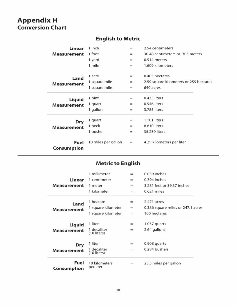
38
Appendix HConversion Chart
English to Metric
Linear Measurement
Land Measurement
Liquid Measurement
Dry Measurement
Fuel Consumption
1 inch = 2.54 centimeters1 foot = 30.48 centimeters or .305 meters1 yard = 0.914 meters1 mile = 1.609 kilometers
1 acre = 0.405 hectares1 square mile = 2.59 square kilometers or 259 hect ares1 square mile = 640 acres
1 pint = 0.473 liters1 quart = 0.946 liters1 gallon = 3.785 liters
1 quart = 1.101 liters1 peck = 8.810 liters1 bushel = 35.239 liters
10 miles per gallon = 4.25 kilometers per liter
Metric to English
Linear Measurement
Land Measurement
Liquid Measurement
Dry Measurement
Fuel Consumption
1 millimeter = 0.039 inches1 centimeter = 0.394 inches1 meter = 3.281 feet or 39.37 inches 1 kilometer = 0.621 miles
1 hectare = 2.471 acres1 square kilometer = 0.386 square miles or 247.1 acres1 square kilometer = 100 hectares
1 liter = 1.057 quarts1 decaliter = 2.64 gallons(10 liters)
1 liter = 0.908 quarts1 decaliter = 0.284 bushels(10 liters)
10 kilometers = 23.5 miles per gallonper liter

Dc Pump Control System Components with Part Numbers
Part number Description 17487 DC Pump Control manual 01500 optional Fm500 Flowmeter Kit 01501 optional Fm750GFn Flowmeter Kit 01504 optional Fm750SS Flowmeter Kit 17485 DC Pump Control Console, Standard 13774 DC Pump Control Console mount Kit 14600 Power/Boom Harness 13222 10 Pin Extension, 180” 14607 10 Pin Extension, 180", with local speed access 14588 optional 5-pin Extension, 180” 14584 optional Boom Harness, 120” 14585 optional Boom Harness, 360” 14582 optional Speed/Flow run-Hold Harness, 120” 14583 optional Speed/Flow run-Hold Harness, 360” 14589 2-pin motor Extension, 180” 14586 optional 2-pin motor Harness, 120” 14587 optional 2-pin motor Harness, 360”
39
Appendix I Replacement Parts List
System WiringPart numbers noted
P/n 14607
YEll oW tIE
P/n 14588180" ext.
P/n 14584 , 1 20"P/n 1 4585 , 3 60"
P/n 14582, 120"P/n 14583, 360"
P/n 14586, 120"P/n 14587, 360"
P/n 14589180" ext.
P/n 14600
optional optional
DC
Pum
p Co
ntro
l

Micro-Trak® Warrantymicro-trak (herein “Seller”) warrants to the original purchaser (herein “Buyer”) that, if any product or part of the product (herein “part”) proves to be defective in material or workmanship, upon inspection and examination by Seller, within one (1) year from the original date-of-purchase, and is returned to Seller with dated proof-of-purchase, transportation prepaid, within thirty (30) days after such defect is discovered, Seller will, at their option and sole discretion, either repair or replace said part, except that the warranty for expendable parts, including but not limited to, light bulbs and batteries shall be thirty (30) days from the original date-of-purchase. Said warranty is valid only when the part has been installed, operated and maintained in strict accordance with the procedures outlined in the manual. Any damage or failure to said part resulting from abuse, misuse, neglect, accidental or improper installation or maintenance, unauthorized modification, use with other products or attributable to acts of God, as determined solely by the Seller, will invalidate the warranty. Said part will not be considered defective if it substantially fulfills the performance specification. Buyer shall be responsible for all maintenance services, if any, all in strict accordance with the procedures outlined in the manual. the warranty does not include labor, installation, replacement parts or repairs, delivery of replacement parts or repairs or time and travel. Said warranty is non-transferrable.
tHE ForEGoInG WArrAntY IS EXCluSIVE AnD In lIEu oF All otHEr WArrAntIES oF mErCHAntABIlItY, FItnESS For PurPoSE AnD oF AnY otHEr tYPE, WHEtHEr EXPrESS or ImPlIED. the Seller’s liability, whether in contract, in tort, under any warranty, in negligence or otherwise, shall not exceed the return of the amount of the purchase price paid by the Buyer, and under no circumstance shall the Seller be liable for special, indirect or consequential damages. Seller neither assumes nor authorizes anyone to assume for it any other obligation or liability in connection with said part. no action, regardless of form, arising out of the transactions under this agreement may be brought by the Buyer more than one (1) year after the cause of action has occurred.
Seller agrees to extend the term of the foregoing warranty period should the Buyer return completed warranty registration information, with dated proof-of-purchase, to the Seller within one (1) year from the original date-of-purchase. All conditions and limitations of said foregoing warranty, except the term of said foregoing warranty, shall apply. Said term shall be extended to a total of three (3) years from the original date-of purchase on display consoles and network communication modules, as defined by Seller, and said term shall be extended to a total of two (2) years from the original date-of-purchase on all other parts, except that the warranty for expendable parts, including but not limited to, light bulbs and batteries shall be thirty (30) days from the original date-of-purchase, and except that the warranty for parts manufactured by someone other than the Seller, including but not limited to, shut-off and control valves, DGPS receivers, memory cards and drives, mapping software, flowmeters and pressure sensors shall be one (1) year from the original date-of-purchase.
Buyer accepts these terms and warranty limitations unless the product is returned to Seller, via proper distribution channels and approved return authorization, with dated proof-of-purchase, transportation prepaid, within fifteen (15) days from the date-of-purchase for refund of the purchase price.
units under warranty should be sent prepaid, with dated proof-of-purchase, within 30 days of discovering defect, to the address below:
MAIL AND UPS:
Micro-Trak Systems, Inc. Attn: Service Department
111 East LeRay Avenue Eagle Lake, MN 56024-0099
At micro-trak Systems, we believe a product that delivers quality and performance at a low cost is what is needed to help today’s operator and the operator of the future compete in the world mar ket.
It is our goal to provide operators with a line of electronic equipment that will help build and maintain an efficient and profitable operation that can be passed on to future generations.
We thank you for your purchase and hope that we can be of service to you in the future.
micro-trak Systems, Inc.
Extended Warranty OptionIt’s simple! Just complete the enclosed registration card(s) for this
product and mail it in and we’ll extend your warranty for up to three years*, at no additional charge.
MAIL IN YOUR REGISTRATION CARD(S) TODAY!
registration Card information is for internal use only.* Some limitations apply. See warranty statement for details.


Agri-Inject, Inc.
5500 E. Hwy 34 P.O. Box 437
Yuma, Colorado 80759 Phone: 970-848-5336 800-446-5328
Fax: 970-848-5338 888-846-5328 E-mail: [email protected]
Web Site: http://www.agri-inject.com