agtron, inc m-series process analyzer owners manual ver… · m-series process analyzer owners...
TRANSCRIPT

1
AGTRON, INC M-SERIES PROCESS ANALYZER
OWNERS MANUAL Ver. 204
Special Applications
Abridged Spectrophotometer Made in the USA
AGTRON INC. 9395 Double R Blvd.
RENO, NV 89521 PHONE:1-775-850-4600 FAX:1-775-850-4611

2
AGTRON M-SERIES OPERATION MANUAL
Version 1.06 / 02/15/05 INTRODUCTION The new M-SERIES is the result of Agtron’s 50 years of experience supplying analytical equipment to the food industry. It is an all solid-state replacement for the previous Agtron M-35 general applications analyzer. Agtron analyzers have become the quality control standard for a variety of products worldwide. These products include, but are not limited to cereal, grain, nuts, tomatoes, potatoes, produce, fruit, baked goods, chips, and snack foods. The AGTRON M-SERIES is a large area (26sq.in.) reflectance abridged spectrophotometer designed to deal with the challenge of measuring color and process related change associated with food. The large viewing area permits analysis of the irregular geometry of such foods as cereal, potato chips, nuts, produce, and baked goods in their natural form without special sample preparation. More importantly, for most applications, the M-SERIES views the product in the same manner as the consumer. M-SERIES FEATURES � Continuous Sample Reading (Updates Reading every two seconds) � Self Contained Micro-Processor Control � Excellent Linearity & Resolution � Ultimate Stability � Long Life Solid State Illumination � Fully Automated Calibration � Easily adapted to analyze many product types � Durable Synthetic Calibration Standards � Calibration Flexibility � High Contrast Backlit LCD Display � Super-Regulated & Isolated Power Supply � Production Environment Construction � Access to Agtron’s 50 years of food analysis application experience MODES OF OPERATION The M-SERIES features eight analytical modes:
3
ALL COLOR MODE- Displays all (four) color bands simultaneously, each as a single number score RED MODE- Displays the analysis result as a single number score for the red color band (640nm) YELLOW MODE- Displays the analysis result as a single number score for the yellow color band (580nm) GREEN MODE- Displays the analysis result as a single number score for the green color band (520nm) BLUE MODE- Displays the analysis result as a single number score for the blue color band (460nm) GREEN/RED RATIO MODE- Special mode for determining the maturity (ripeness) of fresh tomato juice and/or the degree of process (cook) for tomato sauce, paste, and other tomato based products. A lower score signifies a more mature or more processed sample. (Requires optional calibration disk, Petri dish, and Petri dish adapter ring). APPEARANCE MODE- Single number score that relates to consumer perceived differences in the appearance of like-products. This mode mimics the way human vision senses a relative change of chromaticity and saturation for the entire visible spectrum. It is the difference in score from one like-product to another that is significant, and not the actual score. BRIGHTNESS MODE- Single number score based on all-four color bands, where each band has equal significance. It is similar to lightness/darkness or gray scale analysis. A lighter product will have a higher score. For a further description of the analyzer modes, refer to section IV, SELECTING THE OPERATING MODE. INTRODUCTION SUMMARY
4
Simple calibration, non-critical sample preparation, easy to understand single number scores, and robust construction make the M-SERIES the ideal choice for both product development and production quality control. PLEASE TAKE THE TIME TO READ THIS OPERATOR MANUAL BEFORE ATTEMPTING TO USE YOUR AGTRON M-SERIES ANALYZER. CONTACT AGTRON To discuss your specific application, for a more detailed explanation of how the Agtron M-SERIES can solve your product development or production needs, or if you are having problems operating or calibrating the analyzer, please contact us directly: Agtron Incorporated 9395 Double R Blvd. Reno, Nevada 89521 Phone: (775)-850-4600 Fax: (775)-850-4611 E-mail: [email protected] I. INITIAL SETUP

5
Remove the analyzer from the shipping box and carefully inspect for any sign of shipping damage. Contact Agtron immediately if any sign of damage is apparent. A claim for shipping damage needs to be filed immediately with the carrier. IMPORTANT: Keep the box and all packing material. Any equipment returned to Agtron for service must be shipped in the original packaging or Agtron will not accept delivery. The Carton Contains - One M-SERIES Analyzer
- One power Cord with Surge Protector Attached - One Two-Sided Calibration Disk - One Glass Bottomed Sample Dish - One Glass Bottomed Calibration Dish - This Operation Manual
Place the Agtron on a clean and level surface. Keep the cooling fan vent on the back of the unit free of obstruction. Avoid placing the analyzer where it will be directly under overhead light or in direct sunlight. WARNING: Before connecting the analyzer to mains power, check the serial number tag to confirm that the unit is correctly configured for both your Mains Voltage and Frequency. Contact Agtron immediately if a power incompatibility exists. Do not attempt to connect to either an incorrect Voltage or Frequency line. Use only a 3-prong earth grounded connection. Do not bypass the power cord grounding pin or serious electrical shock to the operator and damage to the unit may occur. NOTE: There is no on-off power switch. The unit will power-up as soon as it is connected to mains power. The analyzer is designed for continuous operation and should be left on at all times. The unit uses only about 30 watts of power. Connect the AC power cord to its mating socket on the back of the analyzer. Make certain that the plug is firmly seated. Connect the other end of the power cord to mains power. The display will activate and the unit will begin timing a 45-minute warm-up period. During this 45-minute interval, the screen will display the unit serial number and other information.
6
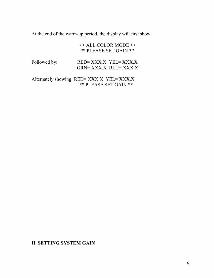
At the end of the warm-up period, the display will first show: << ALL COLOR MODE >> ** PLEASE SET GAIN ** Followed by: RED= XXX.X YEL= XXX.X GRN= XXX.X BLU= XXX.X Alternately showing: RED= XXX.X YEL= XXX.X ** PLEASE SET GAIN ** II. SETTING SYSTEM GAIN

7
System gain must be set anytime the analyzer is restarted after being disconnected from power. It must also be reset whenever the display prompts the operator to do so. System gain may be set as frequently as desired but setting gain once per month is usually sufficient. NOTE: Recalibration of the analyzer is required whenever gain is set. WARNING: Use the sample dish marked “USE ONLY FOR CALIBRATION” for setting gain and normal calibration. Never use this dish for product measurement as residue from samples may damage the calibration disk.
Place the two-sided Calibration Disk into the “Calibrate Only” sample dish, white side down and put the dish in position over the sample window. Depress the SET GAIN Key on the function keypad. The display will ask if the high reference disk is in place. Depress the YES key on the function keypad to confirm the disk is in place. The analyzer will automatically adjust the system gain. This may take several minutes. Do not move the dish or disk during this procedure. When the gain adjustment is finished, the display will first show: << ALL COLOR MODE >> GRN= XXX.X BLU= XXX.X Followed by: RED= XXX.X YEL= XXX.X GRN= XXX.X BLU= XXX.X Alternately showing: RED= XXX.X YEL= XXX.X ** PLEASE CALIBRATE ** This completes the SETTING SYSTEM GAIN procedure. III. CALIBRATION
8
The Agtron M-SERIES has four options for calibration. They are: A) Factory Default Calibration B) Manual Calibration A) Quick Calibration D) Calibrating with Product / Matching the M-35 IMPORTANT: The M-Series uses illumination that is incident to the viewing window. The center frequencies for yellow, green and blue are also slightly different than the M35D. For this reason, even if the unit is calibrated with the same disks and values used for the M35D, product readings will be different. Refer to the PRODUCT CALIBRATION section for the technique necessary to emulate older Agtron analyzers.
A) FACTORY DEFAULT CALIBRATION
This mode resets the calibration references to the factory default values. The default values for the supplied two-sided calibration disk are stored in the analyzers memory and cannot be edited by the operator. The values are obtained from a reference spectrophotometer for each of the four frequencies used by the M-Series analyzer and apply only to the two-sided disk supplied with the unit. These calibration values are traceable and are the “Agtron Standard Values” for calibration. NOTE: The default values are only relative to the two-sided calibration disk supplied with the analyzer. If it becomes necessary to replace the calibration disk, please consult Agtron for assistance. Place the two-sided Calibration Disk into the sample dish, white side down and put the dish in position over the sample window. NOTE: Do not move the dish or disk during this procedure. Depress the DEFAULT CAL key on the function keypad. The display will ask if the high reference disk is on the viewing window. Depress the YES key. The top line of the display will show:

9
== HIGH REFERENCE == The bottom line of the display will quickly display each of the four colors and the relative factory default high reference scores in sequence, stored in the default memory, followed by a confirmation that they have been accepted. When the High Reference default calibration is finished, the display will show: == HIGH REFERENCE == === COMPLETE === Followed by: -- LOW REFERENCE -- The display will also provide additional information and ask if the low disk is on the sample window. Turn the two-sided calibration disk over so that the black side is facing down in the sample dish. NOTE: Do not move the dish or disk during this procedure. Depress the YES key to confirm that the low reference disk is in place. The top line of the Display will show: -- LOW REFERENCE -- The bottom line of the display will quickly display each of the four colors and the relative factory default low scores stored in the default memory, followed by a confirmation that they have been accepted. When the FACTORY DEFAULT CALIBRATE procedure is completed, the display will first show: << ALL COLOR MODE >> GRN= XXX.X BLU= XXX.X Followed by: RED= XXX.X YEL= XXX.X GRN= XXX.X BLU= XXX.X This completes the FACTORY DEFAULT CALIBRATE procedure.
B) MANUAL CALIBRATION

10
This calibration procedure is used when the operator wishes to edit the high and/or low calibration references. Values entered during this procedure will be stored for use in the QUICK CALIBRATE mode. A new analyzer will have initial factory settings that are rounded to 100.0 for the high reference and 05.0 for the low reference until edited by the user. The Factory Default settings can be restored anytime by calibrating using the DEFAULT CAL key. (See “FACTORY DEFAULT CALIBRATION”, III A) NOTE: MANUAL CALIBRATE is the only mode that allows the operator to edit calibration values. NOTE: Analytical resolution can be expanded or compressed by changing the high and low values. Consult Agtron for assistance. Place the “Calibrate Only” sample dish onto the viewing window. Place the two-sided calibration disk, white side down, into the sample dish. NOTE: Do not move the dish or disk during this procedure. Depress the CAL key on the function keypad. The display will ask if the high calibration reference is in place. Depress the YES key to confirm the high reference is in place. The display will show: == HIGH REFERENCE == RED SCORE : 100.0 Enter the desired value using the numeric keypad and depress the E key, or depress the E key to enter the value already displayed. The display will first show: == HIGH REFERENCE == ACCEPTED : 100.0 Followed by: == HIGH REFERENCE == YELOW SCORE : 100.0 Enter the desired value using the numeric keypad and depress the E key, or depress the E key to enter the value already displayed.

11
The display will first show: == HIGH REFERENCE == ACCEPTED : 100.0 Followed by: == HIGH REFERENCE == GREEN SCORE : 100.0 Enter the desired value using the numeric keypad and depress the E key, or depress the E key to enter the value already displayed. The display will first show: == HIGH REFERENCE == ACCEPTED : 100.0 Followed by: == HIGH REFERENCE == BLUE SCORE : 100.0 Enter the desired value using the numeric keypad and depress the E key, or depress the E key to enter the value already displayed. The display will first show: == HIGH REFERENCE == ACCEPTED : 100.0 Followed by: == HIGH REFERENCE == COMPLETE Followed by: -- LOW REFERENCE -- The display will also ask if the low calibration reference is in place. Turn the two-sided calibration disk over in the dish so that the black side is facing down. NOTE: Do not move the dish or disk during this procedure. Depress the YES key on the function keypad to confirm that the low reference is in place. NOTE: To change the sign from plus (+) to minus (-), Depress the (+/-) key. The display will show: -- LOW REFERENCE -- RED SCORE : +05.0
12
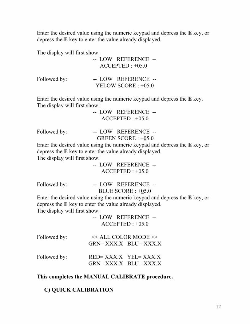
Enter the desired value using the numeric keypad and depress the E key, or depress the E key to enter the value already displayed. The display will first show: -- LOW REFERENCE -- ACCEPTED : +05.0 Followed by: -- LOW REFERENCE -- YELOW SCORE : +05.0 Enter the desired value using the numeric keypad and depress the E key. The display will first show: -- LOW REFERENCE -- ACCEPTED : +05.0 Followed by: -- LOW REFERENCE -- GREEN SCORE : +05.0 Enter the desired value using the numeric keypad and depress the E key, or depress the E key to enter the value already displayed. The display will first show: -- LOW REFERENCE -- ACCEPTED : +05.0 Followed by: -- LOW REFERENCE -- BLUE SCORE : +05.0 Enter the desired value using the numeric keypad and depress the E key, or depress the E key to enter the value already displayed. The display will first show: -- LOW REFERENCE -- ACCEPTED : +05.0 Followed by: << ALL COLOR MODE >> GRN= XXX.X BLU= XXX.X Followed by: RED= XXX.X YEL= XXX.X GRN= XXX.X BLU= XXX.X This completes the MANUAL CALIBRATE procedure.
C) QUICK CALIBRATION
13
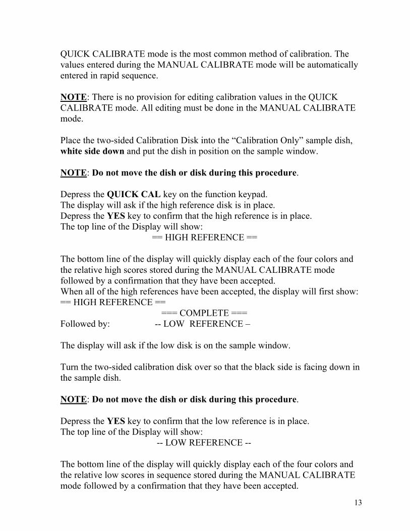
QUICK CALIBRATE mode is the most common method of calibration. The values entered during the MANUAL CALIBRATE mode will be automatically entered in rapid sequence. NOTE: There is no provision for editing calibration values in the QUICK CALIBRATE mode. All editing must be done in the MANUAL CALIBRATE mode. Place the two-sided Calibration Disk into the “Calibration Only” sample dish, white side down and put the dish in position on the sample window. NOTE: Do not move the dish or disk during this procedure. Depress the QUICK CAL key on the function keypad. The display will ask if the high reference disk is in place. Depress the YES key to confirm that the high reference is in place. The top line of the Display will show: == HIGH REFERENCE == The bottom line of the display will quickly display each of the four colors and the relative high scores stored during the MANUAL CALIBRATE mode followed by a confirmation that they have been accepted. When all of the high references have been accepted, the display will first show: == HIGH REFERENCE == === COMPLETE === Followed by: -- LOW REFERENCE – The display will ask if the low disk is on the sample window. Turn the two-sided calibration disk over so that the black side is facing down in the sample dish. NOTE: Do not move the dish or disk during this procedure. Depress the YES key to confirm that the low reference is in place. The top line of the Display will show: -- LOW REFERENCE -- The bottom line of the display will quickly display each of the four colors and the relative low scores in sequence stored during the MANUAL CALIBRATE mode followed by a confirmation that they have been accepted.

14
When the QUICK CALIBRATE procedure is completed, the display will first show: << ALL COLOR MODE >> GRN= XXX.X BLU= XXX.X Followed by: RED= XXX.X YEL= XXX.X GRN= XXX.X BLU= XXX.X This completes the QUICK CALIBRATE procedure.
D) CALIBRATING WITH PRODUCT TO A DESIRED SCORE
This mode is used to achieve customer-desired scores or to emulate M35D product scores. Two samples of the product to be referenced are required. These samples should have a difference of at least 20 points measured on the M-SERIES or the M-35D using Agtron standard calibration. 1 Select the desired color mode on the M35D 2 Calibrate the M35D using the normal method that you use for the product to be measured 3 Read the two samples and record the scores. 4 Without disturbing the samples, transfer them to the M-Series analyzer to be calibrated 5 Select the desired color mode (or the matching color mode that was used on the M35D) to establish the reference scores 6 Depress the CAL key 7 When the display asks if the high reference is on the viewing window, place the product sample with the higher score on the window and depress the YES key 8 Enter the score desired or the score obtained from the M35D and depress the E key 9 When the display asks if the low reference is on the viewing window, place the product sample with the lower score on the window and depress the YES key Enter the score desired or the score obtained from the M35D and depress the E key Place the two-sided calibration disk supplied with the M-Series, white side down, into its calibration dish and place it onto the viewing window.
15
Record the score for future High Calibration Reference for this product Turn the disk over so that the black side faces down Record the score for future Low Calibration Reference for this product Use the two-sided Calibration Disk, the QUICK CAL procedure, and the scores recorded above for future production calibration when calibrating for that product category.
IV. SELECTING THE OPERATING MODE
16
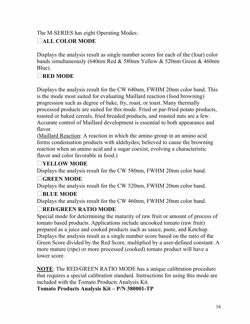
The M-SERIES has eight Operating Modes: � ALL COLOR MODE Displays the analysis result as single number scores for each of the (four) color bands simultaneously (640nm Red & 580nm Yellow & 520nm Green & 460nm Blue). � RED MODE Displays the analysis result for the CW 640nm, FWHM 20nm color band. This is the mode most suited for evaluating Maillard reaction (food browning) progression such as degree of bake, fry, roast, or toast. Many thermally processed products are suited for this mode. Fried or par-fried potato products, toasted or baked cereals, fried breaded products, and roasted nuts are a few. Accurate control of Maillard development is essential to both appearance and flavor. (Maillard Reaction: A reaction in which the amino group in an amino acid forms condensation products with aldehydes; believed to cause the browning reaction when an amino acid and a sugar coexist, evolving a characteristic flavor and color favorable in food.) � YELLOW MODE Displays the analysis result for the CW 580nm, FWHM 20nm color band. � GREEN MODE Displays the analysis result for the CW 520nm, FWHM 20nm color band. � BLUE MODE Displays the analysis result for the CW 460nm, FWHM 20nm color band. � RED/GREEN RATIO MODE Special mode for determining the maturity of raw fruit or amount of process of tomato based products. Applications include uncooked tomato (raw fruit) prepared as a juice and cooked products such as sauce, paste, and Ketchup. Displays the analysis result as a single number score based on the ratio of the Green Score divided by the Red Score, multiplied by a user-defined constant. A more mature (ripe) or more processed (cooked) tomato product will have a lower score. NOTE: The RED/GREEN RATIO MODE has a unique calibration procedure that requires a special calibration standard. Instructions for using this mode are included with the Tomato Products Analysis Kit. Tomato Products Analysis Kit – P/N 380001-TP

17
(Agtron P/N 380001-TP kit includes a special two-sided tomato calibration disk, two glass sample dishes, and a viewing window adapter ring) � APPEARANCE MODE Displays the analysis result as a single number score based on all four colors, with each color biased to emulate the human eye’s sensitivity to that color band. This score relates to how differences in the complex color of like-products will appear to the consumer. It is the difference in score from one like-product to another that is significant and not the actual score. With Factory Default Calibration, a change of one point is perceivable. � BRIGHTNESS MODE Displays the analysis result as a single number score based on all (four) color bands where each color has equal significance. It is similar to lightness/darkness or gray scale analysis. A lighter product will have a higher score. With Factory Default Calibration, a change of two points is considered perceivable. In most instances, each time a new mode is selected, the analyzer will prompt a recalibration. TO SELECT A MODE Depress the MODE key on the function keypad The display will show: � KEY SCROLLS MODES
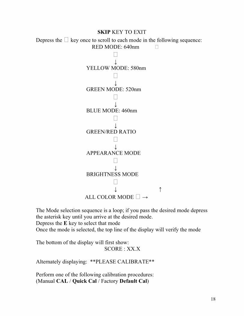
18
SKIP KEY TO EXIT Depress the � key once to scroll to each mode in the following sequence: RED MODE: 640nm � � ↓ YELLOW MODE: 580nm � ↓ GREEN MODE: 520nm � ↓ BLUE MODE: 460nm � ↓ GREEN/RED RATIO � ↓ APPEARANCE MODE � ↓ BRIGHTNESS MODE � ↓ ↑ ALL COLOR MODE � → The Mode selection sequence is a loop; if you pass the desired mode depress the asterisk key until you arrive at the desired mode. Depress the E key to select that mode Once the mode is selected, the top line of the display will verify the mode The bottom of the display will first show: SCORE : XX.X Alternately displaying: **PLEASE CALIBRATE** Perform one of the following calibration procedures: (Manual CAL / Quick Cal / Factory Default Cal)

19
The analyzer may be returned from any mode to the ALL COLOR MODE at any time by depressing the AGTRON NUMBER key If you experience difficulty during the calibration procedure, or you make a mistake, return to the ALL COLOR MODE by depressing the AGTRON NUMBER key and start over. NOTE: It may be necessary to depress the SKIP key first to exit from certain steps in a calibration routine before depressing the AGTRON NUMBER key. NOTE: When returning to the ALL COLOR MODE with the AGTRON NUMBER key, depending on the mode you are leaving and the calibration configuration of that mode, the analyzer may not prompt recalibration. If recalibration is not prompted, the analyzer will use the previous calibration. Recalibrate if this is not the calibration desired. V. SAMPLE PREPARATION Agtron has over 50 years of experience analytically assessing food products. Please feel free to contact us for M-SERIES application assistance In most cases, it is best to evaluate food samples without altering their natural geometry There are four main geometry categories for dry product:

20
Powders Small Particle Medium Particle Large Particle Very Large Particle Each of the four main geometry categories has two sub-categories: Uniform Geometry- All particles are of the same shape and size Irregular Geometry- Particles vary in shape and size For all main and sub-categories of geometry there are two color classifications: Color Homogenous- Uniform color throughout the sample Color Non-homogenous- Variation in color throughout the sample The M-SERIES Analyzer’s large viewing area allows products of all categories, sub-categories, and color classifications to be evaluated. POWDERS Any product similar to flour in consistency can be considered a powder. If the product to be evaluated is not color homogenous to the eye, it should be well stirred before preparing the sample for testing. To prepare the sample for evaluation: Pour the sample into the sample dish covering the entire bottom of the dish. Spread the sample evenly and use a product depth of about ½ inch of product. Be careful not to compress/compact the powder as this will alter results. SMALL PARTICLE Granular products similar to table salt, coarse grain, coffee, and bread- crumbs would be considered small particle products. If the product to be evaluated is not color homogenous to the eye, it should be well stirred before preparing the sample for testing. To prepare the sample for evaluation: Pour the sample into the sample dish covering the entire bottom of the dish. Spread the sample evenly and use a product depth of about ¾ inch of product. As with powders, be careful not to compress/compact the powder as this will alter results. MEDIUM PARTICLE Products like rice, peppercorns, capers, and caviar are typical of medium particle products. If the product to be evaluated is not color homogenous to the eye, it should be well stirred before preparing the sample for testing.

21
To prepare the sample for evaluation: Pour the sample into the sample dish covering the entire bottom of the dish. Spread the sample evenly and use a product depth of about one inch of product. LARGE PARTICLE Products like nuts, cereal, candies, and dried beans are typical of the large particle classification. Many of these types of products are both color non-homogenous and have irregular geometry. To prepare a sample for evaluation: Cover the entire surface of the bottom of the sample dish. Distribute the various colors and geometric shapes randomly. Layer the sample to cover any geometric voids. Use a 1½-inch depth of product. VERY LARGE PARTICLE Potato chips, pretzels, snack mix, and tortilla chips are products typical of the very large particle classification. To prepare a sample for evaluation: Cover the entire surface of the bottom of the sample dish. Distribute the various colors and geometric shapes randomly. Layer the sample to cover any geometric voids. Continue to layer product until the sample dish is full. Do not compress the sample. IMPORTANT: It may be advantageous to cover the sample dish during sample testing to prevent ambient light from affecting results. To determine if it is necessary, cover a prepared sample with a dark opaque material such as black craft paper while it sits on the viewing window to see if the score is changed appreciably (more than 0.2). VI. PRODUCT APPLICATION NOTES General sample preparation techniques may not suit every product. The objective of good sample preparation is to provide accurate and repeatable data. To accomplish satisfactory results, some products may require milling, chopping, sieving, compression, special sample dishes or masks.
22
For most common food products, Agtron can recommend the analytical mode and calibration method. Selecting the correct analytical mode for special products may require experimentation. Consult Agtron for special application assistance M-SERIES SPECIFICATIONS GENERAL: Self Contained Visible-Spectrum Abridged Spectrophotometer VIEWING AREA: Circular, Approximately 26 Inches-Square MEASUREMENT GEOMETRY: Diffused Illuminate
23
Collimated Field-Coincident Detection MEASUREMENT BAND SPECIFICATIONS: Red Band – CW 640nm (+/- 2.5nm), FWHM 20nm (+/- 2.5nm) Yellow Band – CW 580nm (+/- 2.5nm), FWHM 20nm (+/- 2.5nm) Green Band – CW 520nm (+/- 2.5nm), FWHM 20nm (+/- 2.5nm) Blue Band – CW 460nm (+/- 2.5nm), FWHM 20nm (+/- 2.5nm) ANALYTICAL RESOLUTION: +/- 0.10% LINEARITY: +/- 0.20% INTER INSTRUMENT AGREEMENT: +/- 0.30% REFLECTANCE SCALE: 00.0 to 100.0% Absolute ILLUMINATE: Broad Spectrum Solid-State ILLUMINATE MTBF: 10 Years Continuous Duty CONTROL & LOGIC: Dual Microprocessor DISPLAY: Dual line 42 Character Back Illuminated Alpha/Numeric LCD ANALYZER DUTY RATING: Continuous POWER SUPPLY: Super Regulated Solid-State, 1% Line / Load regulation High-Q EMI filtered / 60db Line Isolation POWER REQUIREMENT: 30 watts Factory configured for one of the following mains connections- Ο100volt, 120volt, 220volt, 240voltΝ 50/60hz
WARRANTY and
Return for Repair Procedures

24
Agtron Inc. warrants this product to be free of defects in material and workmanship for a period of One Year from date of purchase (date of invoice). This warranty is valid only to the original customer. This warranty does not extend to Agtron equipment used for any than its intended application, to external appearance or damage resulting from improper installation, line voltage, alteration, misuse, neglect, or abuse. Agtron equipment requiring warranty repair should be returned under a Return For Repair authorization number (RFR) provided by Agtron and repackaged in the original shipping container and packing materials. Warranty repairs must be accompanied by a copy of the original sales invoice as proof of date of purchase. The customer must pay return freight to Agtron and insure the unit for full value, Agtron will not assume the responsibility for any shipping damage. Agtron will pay the return freight to customer. Unit returned for service should not include additional hardware, instruction manual, or other inclusions.
25
AGTRON, INC._______________ Reno, Nevada USA CE MARKING DECLARATION OF COMPLIANCE This declaration certifies that this product is in total compliance with CE - Marking and CE Legislation. _______________________ Certified Agtron, Incorporated