ahu eurovent iskid part 1
TRANSCRIPT

1
European Standards
Eurovent Certification AHU
Istanbul – 13 November 2009
Ankara – 14 November 2009
Kees van Haperen
chairman
Eurovent WG6C
2
Abstract training course
Part 1
• European Standard EN 1886
• European Standard EN 13053
Break
Part 2
• Eurovent certification procedure for AHUs
• Eurovent Energy Labelling System for AHUs
• Advantages of Eurovent Certification
2
Part 1
European Standards
Kees van Haperen
chairman
Eurovent WG6C
4
CEN
One European Standard = 30 National Standards
• National Standard Bodies adopt European Standard
• All national Standards identical
Heating, cooling, ventilation
• CEN Technical Committee 156
• CEN Working Group 5
3
5
EN 1886
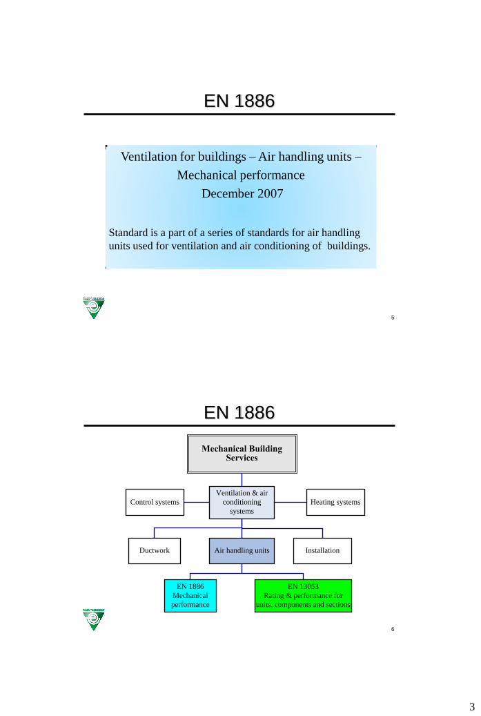
Ventilation for buildings – Air handling units –
Mechanical performance
December 2007
Standard is a part of a series of standards for air handling
units used for ventilation and air conditioning of buildings.
6
EN 1886
Control systems
Ventilation & air
conditioning
systems
Heating systems
Mechanical Building Services
Ductwork
Air handling units
Installation
EN 1886
Mechanical
performance
EN 13053
Rating & performance for
units, components and sections
4
7
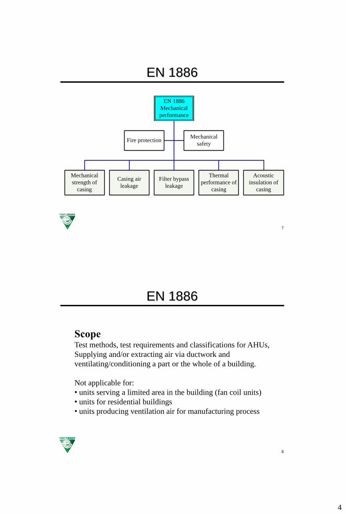
EN 1886
Mechanical
strength of
casing
Casing air
leakage
Filter bypass
leakage
Fire protection
Acoustic
insulation of
casing
Thermal
performance of
casing
Mechanical
safety
EN 1886
Mechanical
performance
8
EN 1886
ScopeTest methods, test requirements and classifications for AHUs,
Supplying and/or extracting air via ductwork and
ventilating/conditioning a part or the whole of a building.
Not applicable for:
• units serving a limited area in the building (fan coil units)
• units for residential buildings
• units producing ventilation air for manufacturing process

5
9
EN 1886
TEST CRITERIA CASINGMODEL
BOX*
REAL
UNIT**
Mechanical strength X X
Air leakage X X
Filter bypass leakage X X
Thermal transmittance X –
Thermal bridging X –
Acoustic insulation X –
* General classification; marked (M)
** Particular classification; marked (R)
10
EN 1886
Model box• empty enclosure with standard casing construction features
• internal height and width between 0,9 and 1,4 m
• total external surface between 10 and 30 m2
• assembly of at least 2 sections
• each section shall have (at least) one access door
• filter frame installed without filter medium
• assembly in accordance with normal production procedures
Real unit• factory made assembly comprising air handling functions
6
11
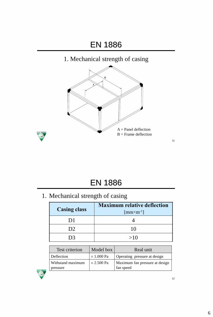
EN 1886
A = Panel deflection
B = Frame deflection
1. Mechanical strength of casing
12
EN 1886
Casing classMaximum relative deflection
[mm×m-1]
D1 4
D2 10
D3 >10
Test criterion Model box Real unit
Deflection ± 1.000 Pa Operating pressure at design
Withstand maximum
pressure
± 2.500 Pa Maximum fan pressure at design
fan speed
1. Mechanical strength of casing
7
13
EN 1886
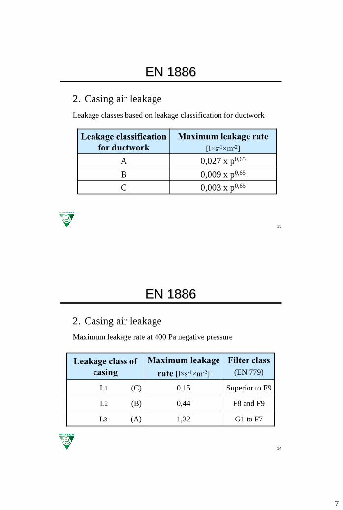
2. Casing air leakage
Leakage classes based on leakage classification for ductwork
Leakage classification
for ductwork
Maximum leakage rate
[l×s-1×m-2]
A 0,027 x p0,65
B 0,009 x p0,65
C 0,003 x p0,65
14
EN 1886
2. Casing air leakage
Maximum leakage rate at 400 Pa negative pressure
Leakage class of
casing
Maximum leakage
rate [l×s-1×m-2]
Filter class
(EN 779)
L1 (C) 0,15 Superior to F9
L2 (B) 0,44 F8 and F9
L3 (A) 1,32 G1 to F7
8
15
EN 1886
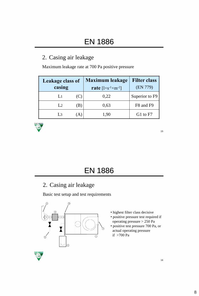
2. Casing air leakage
Maximum leakage rate at 700 Pa positive pressure
Leakage class of
casing
Maximum leakage
rate [l×s-1×m-2]
Filter class
(EN 779)
L1 (C) 0,22 Superior to F9
L2 (B) 0,63 F8 and F9
L3 (A) 1,90 G1 to F7
16
EN 1886
2. Casing air leakage
Basic test setup and test requirements
• highest filter class decisive
• positive pressure test required if
operating pressure > 250 Pa
• positive test pressure 700 Pa, or
actual operating pressure
if >700 Pa
9
17
EN 1886
3. Filter bypass leakage
• Filter bypass leakage is related to filter class
• Test pressure differential 400 Pa
• Leakage rate is a percentage of nominal air flow rate
• For model box nominal flow is 0,93 m3/s for full filter (=2,5 m/s
face velocity on 610 x 610 mm square)
• Bypass leakage is the total amount of unfiltered air supplied to
the building; hence:- for upstream filters, bypass around filter cells + casing leakage
between filter and fan
- for downstream filters, only bypass around filter cells
18
EN 1886
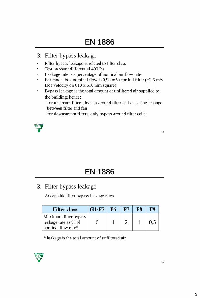
3. Filter bypass leakage
Acceptable filter bypass leakage rates
Filter class G1-F5 F6 F7 F8 F9
Maximum filter bypass
leakage rate as % of
nominal flow rate*
6 4 2 1 0,5
* leakage is the total amount of unfiltered air

10
19
EN 1886
3. Filter bypass leakage
Test setup for upstream bypass leakage test
qLtot = qL + qLf Bypass lekkage: qLto
20
EN 1886
4. Thermal transmittance
Mean heat loss coefficient (thermal transmittance “U”) is only
measured on model box and is calculated as:
air
el
tA
PU
U = thermal transmittance [W×m-2×K-1]Pel = electrical power input for heater(s) and circulating fans [W]A = external surface area [m2]Δtair = air to air differential temperature (ti-ta) [K]ti = mean internal air temperature [°C]ta = mean external air temperature [°C]
11
21
EN 1886
4. Thermal transmittance
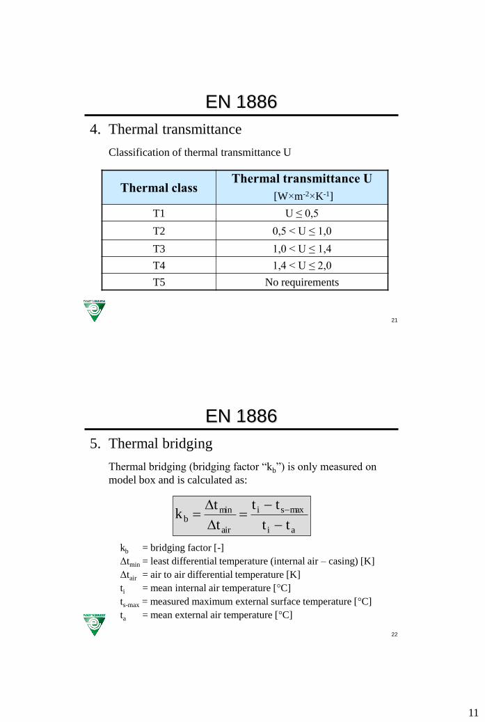
Classification of thermal transmittance U
Thermal classThermal transmittance U
[W×m-2×K-1]
T1 U ≤ 0,5
T2 0,5 < U ≤ 1,0
T3 1,0 < U ≤ 1,4
T4 1,4 < U ≤ 2,0
T5 No requirements
22
EN 1886
5. Thermal bridging
Thermal bridging (bridging factor “kb”) is only measured on
model box and is calculated as:
ai
maxsi
air
minb
tt
tt
t
tk
kb = bridging factor [-]
Δtmin = least differential temperature (internal air – casing) [K]
Δtair = air to air differential temperature [K]
ti = mean internal air temperature [°C]
ts-max = measured maximum external surface temperature [°C]
ta = mean external air temperature [°C]

12
23
EN 1886
5. Thermal bridging
Classification of thermal bridging factor kb
Thermal class Thermal bridging factor kb
TB1 0,75 ≤ kb < 1,00
TB2 0,60 ≤ kb < 0,75
TB3 0,45 ≤ kb < 0,60
TB4 0,30 ≤ kb < 0,45
TB5 No requirements
In class TB3 and TB4, 1% of the external surface may have lower bridging class
24
EN 1886
5. Thermal bridging
Practical application of bridging factor kb
ti=10°
ta=30
°
tmin
Risk of external condensation if internal temperature
is lower than external temperature!
After conversion of formula the minimum external
surface temperature is calculated with equation below
iabiminiminiab
ia
iminb ttkttttttk
tt
ttk
Example: Result:Bridging factor = 0,6 tmin = 10° + 0,6×(30° - 10°) = 22°C
Internal air temperature 10°C no condensation if dewpoint ta < 22°
External air temperature 30°C maximum relative humidity 62%

13
25
EN 1886
6. Acoustic insulation of casing
Measurement of sound insertion loss value Dp
Dp is the difference of the measured sound pressure level in a
sound source-enveloping surface without and with model box
around the source.
Values measured in octave bands 125 – 8000 Hz.
26
EN 1886
6. Acoustic insulation of casing
Sound source on reflecting floor

14
27
EN 1886
Measurement of LP-SOURCE
in enveloping surface,
averaged per octave band
6. Acoustic insulation of casing
Enveloping surface around sound source
28
EN 1886
Measurement of LP-ENCLOSURE
in enveloping surface,
averaged per octave band
Dp = LP-SOURCE – LP-ENCLOSURE
6. Acoustic insulation of casing
Enveloping surface around model box; sound source in
model box
15
29
EN 1886
7. Fire protection
Design and construction requirements; not relevant for
Eurovent Certification
8. Mechanical safety
Design and construction requirements; not relevant for
Eurovent Certification
30
EN 13053
Ventilation for buildings – Air handling units –
Rating and performance for units, components and
sections
August 2006
Revision prEN 13053rev – 2009®
Standard is a part of a series of standards for air handling
units used for ventilation and air conditioning of buildings.

16
31
EN 13053
Damper section
Mixing section
Fan section
Air handling unit
as a whole
Humidifiers
Filter section
Heat recovery
systems
EN 13053
Rating & performance for units,
components and sections
Coils
32
EN 13053
ScopeTest methods and requirements for ratings and performance
of AHUs as a whole. Requirements, recommendations,
classification and testing of specific components and sections
of AHUs.
Applicable to standardised designs in a range of sizes and to
custom-designed units.
Not applicable for:
• units serving a limited area in the building (fan coil units)
• units for residential buildings
• units producing ventilation air for manufacturing process

17
33
EN 13053
Ratings and performance of the entire AHU
1. Testing of aerodynamic performanceAir volume flow rate versus external total pressure
- Ptotal = Ptotal-outlet – Ptotal-inlet
- average filter pressure drop is simulated by increasing the external
total pressure with a value (design – initial)
- if final filter pressure drop is design pressure drop the correction
value on external pressure shall be (final – initial)
- testing is performed with dry cooling coils
- air volume flow rate measured in accordance with ISO 5801
- testing of a unit with heat recovery shall be performed taking the
leakage into consideration
- characteristics shall be converted to standard air density 1,2 kg/m3
34
EN 13053
Ratings and performance of the entire AHU
1. Testing of aerodynamic performance
Air volume flow rate versus absorbed motor power
- if fan speed control (e.g. frequency inverter) is required, the
absorbed power shall include the losses in the speed control device
- characteristics shall be converted to standard air density 1,2 kg/m3
- multiple measurements shall be presented for a stated nominal fan
speed, but without corrections for inherent speed deviations caused
by variable motor loads
18
35
EN 13053
Ratings and performance of the entire AHU
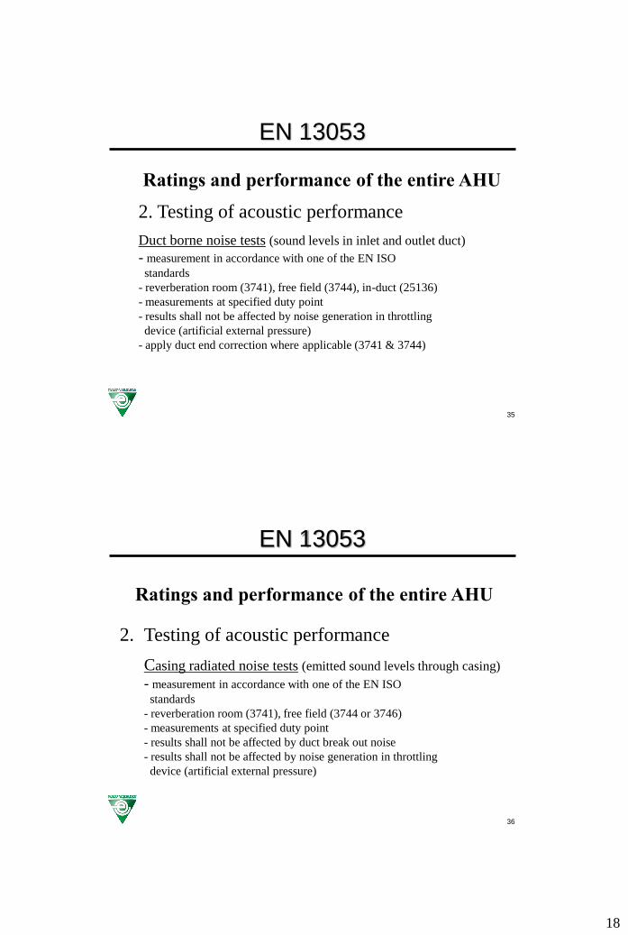
2. Testing of acoustic performance
Duct borne noise tests (sound levels in inlet and outlet duct)
- measurement in accordance with one of the EN ISO
standards
- reverberation room (3741), free field (3744), in-duct (25136)
- measurements at specified duty point
- results shall not be affected by noise generation in throttling
device (artificial external pressure)
- apply duct end correction where applicable (3741 & 3744)
36
EN 13053
Ratings and performance of the entire AHU
2. Testing of acoustic performance
Casing radiated noise tests (emitted sound levels through casing)
- measurement in accordance with one of the EN ISO
standards
- reverberation room (3741), free field (3744 or 3746)
- measurements at specified duty point
- results shall not be affected by duct break out noise
- results shall not be affected by noise generation in throttling
device (artificial external pressure)
19
37
EN 13053
Ratings and performance of the entire AHU
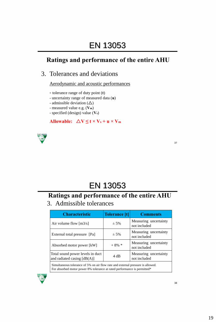
3. Tolerances and deviations
Aerodynamic and acoustic performances
- tolerance range of duty point (t)
- uncertainty range of measured data (u)
- admissible deviation ()
- measured value e.g. (Vm)
- specified (design) value (Vs)
Allowable: V ≤ t × Vs + u × Vm
38
EN 13053Ratings and performance of the entire AHU
3. Admissible tolerances
Characteristic Tolerance [t] Comments
Air volume flow [m3/s] ± 5%Measuring uncertainty
not included
External total pressure [Pa] ± 5%Measuring uncertainty
not included
Absorbed motor power [kW] + 8% *Measuring uncertainty
not included
Total sound power levels in duct
and radiated casing [dB(A)]4 dB
Measuring uncertainty
not included
Simultaneous tolerance of 5% on air flow rate and external pressure is allowed.
For absorbed motor power 8% tolerance at rated performance is permitted*
20
39
EN 13053
Ratings and performance of the entire AHU
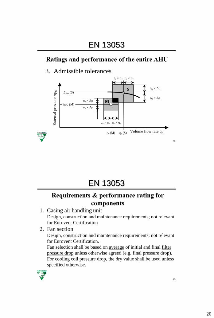
3. Admissible tolerances
tv qv
tp p
ptu (S)
ptu (M)
Exte
rnal
pre
ssure
p
tu
Volume flow rate qv
S
uv qv
tp p up p
up p
tv qv
uv qv
qv (M) qv (S)
M
40
EN 13053
Requirements & performance rating for
components1. Casing air handling unit
Design, construction and maintenance requirements; not relevant
for Eurovent Certification
2. Fan sectionDesign, construction and maintenance requirements; not relevant
for Eurovent Certification.
Fan selection shall be based on average of initial and final filter
pressure drop unless otherwise agreed (e.g. final pressure drop).
For cooling coil pressure drop, the dry value shall be used unless
specified otherwise.

21
41
EN 13053
Requirements & performance rating for components
2. Fan section: classes of average velocity®Velocities based on internal filter -or fan cross section!
Class Air velocity [m/s]
V1 ≤ 1,6
V2 1,6 < v ≤ 1,8
V3 1,8 < v ≤ 2,0
V4 2,0 < v ≤ 2,2
V5 2,2 < v ≤ 2,5
V6 2,5 < v ≤ 2,8
V7 2,8 < v ≤ 3,2
V8 3,2 < v ≤ 3,6
V9 v > 3,6
Proportional steps ISO 3: R20 series
42
EN 13053
Requirements & performance rating for
components
2. Fan section: absorbed motor power®
Reference value for absorbed motor power fan + drive
Pmref = reference value absorbed power [kW]
pstat = available static pressure (pinternal + pexternal) [Pa]
qv = air flow rate of the fan [m3/s]
22
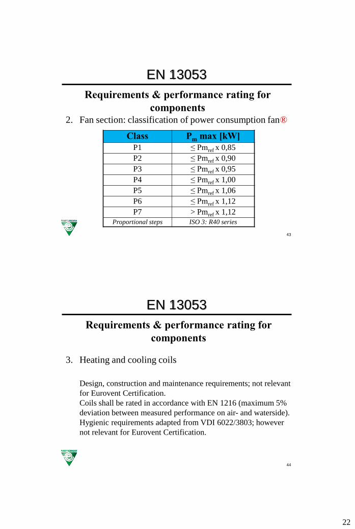
43
EN 13053
Requirements & performance rating for
components2. Fan section: classification of power consumption fan®
Class Pm max [kW]
P1 ≤ Pmref x 0,85
P2 ≤ Pmref x 0,90
P3 ≤ Pmref x 0,95
P4 ≤ Pmref x 1,00
P5 ≤ Pmref x 1,06
P6 ≤ Pmref x 1,12
P7 > Pmref x 1,12
Proportional steps ISO 3: R40 series
44
EN 13053
Requirements & performance rating for
components
3. Heating and cooling coils
Design, construction and maintenance requirements; not relevant
for Eurovent Certification.
Coils shall be rated in accordance with EN 1216 (maximum 5%
deviation between measured performance on air- and waterside).
Hygienic requirements adapted from VDI 6022/3803; however
not relevant for Eurovent Certification.
23
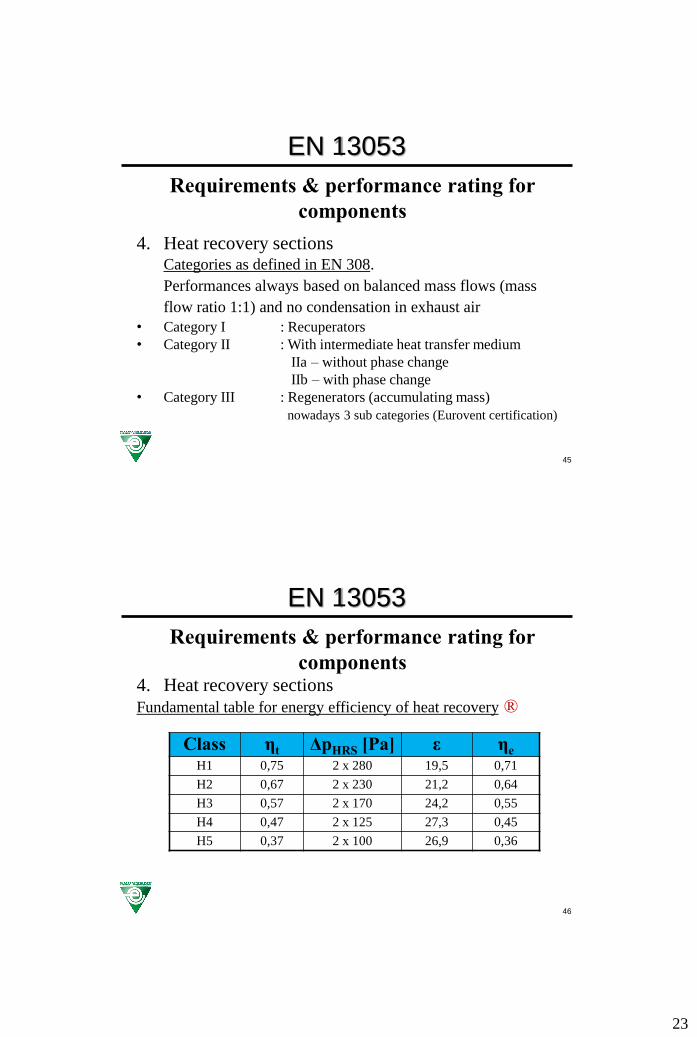
45
EN 13053
Requirements & performance rating for
components
4. Heat recovery sectionsCategories as defined in EN 308.
Performances always based on balanced mass flows (mass
flow ratio 1:1) and no condensation in exhaust air
• Category I : Recuperators
• Category II : With intermediate heat transfer medium
IIa – without phase change
IIb – with phase change
• Category III : Regenerators (accumulating mass)
nowadays 3 sub categories (Eurovent certification)
46
EN 13053
Requirements & performance rating for
components4. Heat recovery sections
Fundamental table for energy efficiency of heat recovery ®
Class ηt ΔpHRS [Pa] ε ηe
H1 0,75 2 x 280 19,5 0,71
H2 0,67 2 x 230 21,2 0,64
H3 0,57 2 x 170 24,2 0,55
H4 0,47 2 x 125 27,3 0,45
H5 0,37 2 x 100 26,9 0,36
24
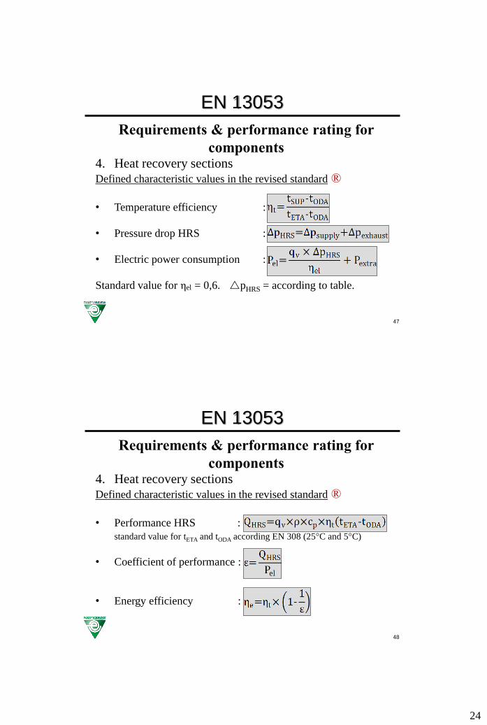
47
EN 13053
Requirements & performance rating for
components4. Heat recovery sections
Defined characteristic values in the revised standard ®
• Temperature efficiency :
• Pressure drop HRS :
• Electric power consumption :
Standard value for ηel = 0,6. pHRS = according to table.
48
EN 13053
Requirements & performance rating for
components4. Heat recovery sections
Defined characteristic values in the revised standard ®
• Performance HRS :
standard value for tETA and tODA according EN 308 (25°C and 5°C)
• Coefficient of performance :
• Energy efficiency :
25
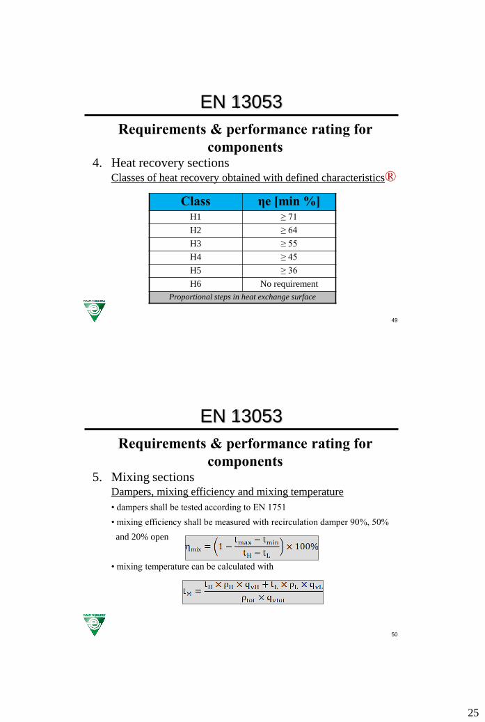
49
EN 13053
Requirements & performance rating for
components4. Heat recovery sections
Classes of heat recovery obtained with defined characteristics®
Class ηe [min %]H1 ≥ 71
H2 ≥ 64
H3 ≥ 55
H4 ≥ 45
H5 ≥ 36
H6 No requirement
Proportional steps in heat exchange surface
50
EN 13053
Requirements & performance rating for
components5. Mixing sections
Dampers, mixing efficiency and mixing temperature
• dampers shall be tested according to EN 1751
• mixing efficiency shall be measured with recirculation damper 90%, 50%
and 20% open
• mixing temperature can be calculated with

26
51
EN 13053
Requirements & performance rating for
components5. Mixing sections
Classification mixing temperature efficiency
Class Mixing efficiency [%]
M1 ≥ 95
M2 85 ≤ ηmix < 95
M3 70 ≤ ηmix < 85
M4 50 ≤ ηmix < 70
M5 < 50
52
EN 13053
Requirements & performance rating for
components6. Humidifiers
Design, construction and maintenance requirements; not
relevant for Eurovent Certification.
Hygienic requirements adapted from VDI 6022/3803; however
not relevant for Eurovent Certification.
7. Filter sectionsDesign, construction and maintenance requirements; not
relevant for Eurovent Certification.
Hygienic requirements adapted from VDI 6022/3803; however
not relevant for Eurovent Certification.

27
53
EN 13053
Requirements & performance rating for
components7. Filter sections
Maximum final pressure drop for filters
Filter class Final pressure drop
G1 – G4 150 Pa
F5 – F7 200 Pa
F8 – F9 300 Pa
54
European Standards