aiga 028_06 unmanned air gas plant _design operation
TRANSCRIPT

UNMANNED AIR GAS PLANT: DESIGN & OPERATION AIGA 028/06
GLOBALLY HARMONISED DOCUMENT
Asia Industrial Gases Association
0
298 Tiong Bahru Road, #20-01 Central Plaza, Singapore 168730
Tel : +65 6276 0160 • Fax : +65 6274 9379 Internet : http://www.asiaiga.org

AIGA 028/06
UNMANNED AIR GAS PLANT: DESIGN & OPERATION
Document prepared by the Working Group AWG 3.7:
Harald Bekmann (Air Liquide) Richard Freeman (Air Products)
Brian Golightly (BOC) Juan Pardo (Praxair)
Herman Puype (EIGA) Horst Reipen (Messer)
Inaki Uriarte (Praxair) Lars Wallsten (Linde)
Disclaimer All publications of AIGA or bearing AIGA’s name contain information, including Codes of Practice, safety procedures and other technical information that were obtained from sources believed by AIGA to be reliable and/ or based on technical information and experience currently available from members of AIGA and others at the date of the publication. As such, we do not make any representation or warranty nor accept any liability as to the accuracy, completeness or correctness of the information contained in these publications. While AIGA recommends that its members refer to or use its publications, such reference to or use thereof by its members or third parties is purely voluntary and not binding. AIGA or its members make no guarantee of the results and assume no liability or responsibility in connection with the reference to or use of information or suggestions contained in AIGA’s publications. AIGA has no control whatsoever as regards, performance or non performance, misinterpretation, proper or improper use of any information or suggestions contained in AIGA’s publications by any person or entity (including AIGA members) and AIGA expressly disclaims any liability in connection thereto. AIGA’s publications are subject to periodic review and users are cautioned to obtain the latest edition.
© AIGA 2006 - AIGA grants permission to reproduce this publication provided the Association is acknowledged as the source
ASIA INDUSTRIAL GASES ASSOCIATION 298 Tiong Bahru Road #20-01 Central Plaza Singapore 168730
Tel: +65 62760160 Fax: +65 62749379 Internet: http://www.asiaiga.org

AIGA 028/06
Acknowledgement
This document is adopted from the European Industrial Gases Association document IGC 132/05 ‘Unmanned airgas plant: design and operation.’ Acknowledgement and thanks are hereby given to EIGA for permission granted for the use of their document.

AIGA 028/06
Table of Contents
1 Introduction.......................................................................................................................................1
2 Scope and purpose ..........................................................................................................................1
3 Definitions.........................................................................................................................................1 3.1 Verbal Forms.............................................................................................................................1 3.2 Unmanned Plant .......................................................................................................................1 3.3 Unmanned Operation................................................................................................................1 3.4 Remote Operation.....................................................................................................................2 3.5 Remote Control/Remote Monitoring .........................................................................................2 3.6 Remote Operating Centre (ROC) .............................................................................................2 3.7 Personnel Roles........................................................................................................................2
3.7.1 Plant Owner / Person Responsible for the Plant ...............................................................2 3.7.2 Remote Operator ...............................................................................................................2 3.7.3 Local Operator ...................................................................................................................2 3.7.4 First Responder .................................................................................................................2
4 Safety Aspects of Plant Design ........................................................................................................2 4.1 General Considerations ............................................................................................................2 4.2 Recommendations for Unmanned air gas plants......................................................................3 4.3 Plant location risk ......................................................................................................................4 4.4 Management of Change (MOC) Review...................................................................................4
5 Plant design and retrofit considerations ...........................................................................................4 5.1 Compliance with permits and regulations .................................................................................4 5.2 Shutdown systems ....................................................................................................................4 5.3 Fire & Gas Alarm System..........................................................................................................5 5.4 Remote Detection of Liquid Spillage.........................................................................................5 5.5 Process Equipment Guidelines.................................................................................................6 5.6 Truck Filling Systems ................................................................................................................6 5.7 Distribution Pipeline & Vaporiser Systems................................................................................6
5.7.1 Distribution Pipeline Systems ............................................................................................6 5.7.2 Back-up Vaporiser Systems ..............................................................................................6 5.7.3 Liquid Disposal Systems....................................................................................................7 5.7.4 Fogging Hazards................................................................................................................7
5.8 Control System Guidelines........................................................................................................7 5.9 Design Aspects of Plant Maintenance ......................................................................................9
6 Plant Operation.................................................................................................................................9 6.1 Plant safety requirement ...........................................................................................................9 6.2 Plant Responsibility.................................................................................................................10 6.3 Training and skills ...................................................................................................................10
6.3.1 Plant Operator Training....................................................................................................10 6.3.2 Cooperation between Local & Remote Operators...........................................................10
6.4 Documentation ........................................................................................................................10 6.5 Transfer of plant control ..........................................................................................................11 6.6 Alarm Handling Procedures ....................................................................................................11 6.7 Remote Restart Considerations..............................................................................................11 6.8 Activity communication follow-up ............................................................................................11 6.9 Work Permits...........................................................................................................................12 6.10 Driver – truck filling activities ...............................................................................................12 6.11 Atmospheric monitoring / Man down systems.....................................................................12 6.12 Plant / site security ..............................................................................................................12
6.12.1 Entry / Exit Procedures ....................................................................................................13 7 Routine Maintenance and Conservation ........................................................................................13
7.1 Planned Maintenance and Record Keeping ...........................................................................13 7.2 Lone Worker Tasks .................................................................................................................13

AIGA 028/06
7.3 Training and Skills...................................................................................................................13 7.4 Interface between Operations & Maintenance........................................................................14 7.5 Lock-out Tag-out .....................................................................................................................14
8 Emergency plans and External Notification ...................................................................................14 8.1 First Responder functions .......................................................................................................14 8.2 Remote Operator functions during an emergency..................................................................15 8.3 External Emergency Services.................................................................................................15 8.4 Emergency drills......................................................................................................................15
9 References .....................................................................................................................................15 9.1 AIGA Documents ....................................................................................................................15 9.2 EIGA/IGC Documents .............................................................................................................15 9.3 CGA Documents .....................................................................................................................15 9.4 Other Documents ....................................................................................................................16
10 Appendix A: Process Equipment Guidelines ..............................................................................17
AIGA 028/06
1 Introduction
This document has been written to address issues relating to the increasing number of air gas production facilities that are run unmanned. There are many similarities in the operation of manned & unmanned plants, however there are some differences. These differences are not only in how the plant is operated and maintained, but also how the plant is designed. In particular, designing new unmanned plants or converting existing plants from manned to unmanned operation requires special precautions to maintain an adequate level of safety.
2 Scope and purpose
Unmanned plant functionality can range from a plant with full remote functionality i.e. satellite plant controlled by a Remote Operating Centre (ROC) to a simple plant with a local monitoring system and a dial-out function to alert a local technician. The installations that are included in this document are:
• Air separation plants (with backup systems and site storage as appropriate) • Nitrogen generators • Non cryogenic plants (Pressure swing absorption, Vacuum pressure swing absorption,
Membrane, etc) for oxygen and nitrogen • Pipeline compression stations (including compressed dry air facilities), that are partially or
totally operated from a remote location and that have unmanned operations. Specifically excluded are product supply tanks installed at a customer’s premises, home care units (e.g. concentrators) and non-cryo generators with a capacity of 5 000 kg per day or less. For non-cryo generators from 5 000 – 20 000 kg per day, a proper risk assessment should be made as to which provisions apply. Consideration shall be given to process complexity, location etc when making this assessment. The purpose of this document is to provide guidelines for the design, operation, and maintenance of a plant that will have unmanned operations.
3 Definitions
3.1 Verbal Forms
“Shall” indicates a very strong concern or instruction. “Should” indicates a recommendation. “May“ and “need not” are used when the application is optional. “Will” is used to indicate the future only, not a degree of requirement.
3.2 Unmanned Plant
The unmanned plant includes the Air Separation Units (ASU) or gas generator, storage, filling and back-up systems.
3.3 Unmanned Operation
The condition where a plant operates without the physical presence of a site operator.
1
AIGA 028/06
3.4 Remote Operation
The condition where operational control of a plant is at a location other than the plant site. Such a condition may exist whether or not there are personnel (e.g. performing filling or maintenance tasks) at the plant site.
Remote Operation does not necessarily imply continuous communication with the plant.
3.5 Remote Control/Remote Monitoring
Remote Control of a plant implies two way communication from the plant to/from the ROC (e.g. receiving plant alarm/trip signals & the ability to remotely start/stop machinery etc). Remote Monitoring implies one way communication from the plant to the ROC (e.g. receive only plant alarm/trip signals, plant data etc).
3.6 Remote Operating Centre (ROC)
This is a Centre that remotely monitors and operates a plant or multiple plants. It could be a dedicated centre, be located at a plant site or any other remote location. The ROC may also provide specialist operations support (maintenance, engineering, control systems etc).
3.7 Personnel Roles
3.7.1 Plant Owner / Person Responsible for the Plant
Single point of contact who is responsible for plant operation, maintenance, etc.
3.7.2 Remote Operator
Person remotely located that has control of the plant. The remote operator does not need to be located at the ROC.
3.7.3 Local Operator
Person who is on site and has control of the plant. Personnel who are working at the plant but are not in control of the plant are not considered to be Local Operators.
3.7.4 First Responder
The First Responder is the person that is first to arrive at the physical site of an emergency. This could be the Operator, Customer, Fire Dept., etc.
4 Safety Aspects of Plant Design
4.1 General Considerations
This section briefly introduces the complex subject of safety in plant design and the reader is referred to various documents in section 9.4 for more detailed information. The starting point for evaluation of safety systems is always a review that is focused on safety. This can typically be a “HazOp” for new plant designs or a “What If” analysis for retrofits. Either type of
2
AIGA 028/06
analysis will lead to Hazard Identification and Risk Assessment. The objective of these assessments is to identify the safety features necessary to reduce the risk to the “As Low As Reasonably Practicable” (ALARP) threshold – the necessary safety target set by each country/company. Safety related features may prevent, contain or mitigate the hazard and comprise the following categories:
• Passive Engineering Systems e.g. selection of pipeline materials to eliminate the hazard, tank
bunds to contain the leak etc. • Active Engineering Systems – a device e.g. safety valve, non return valve or instrumentation
(alarms & trips) • Procedural Controls / Human Actions e.g. Operating Instructions, Emergency Response –
plant shutdown, isolation etc.
Ideally plants should have been designed to incorporate controls in the first category (which eliminate or reduce the risk) as these are inherently more reliable than those in the other two categories. Certain safety related features that rely on instrumentation are called Safety Instrumented Systems (SIS) and the following design standards give a systematic approach that is internationally recognised as best practice:
• IEC 61508: Functional Safety of electrical/electronic/programmable electronic safety related
systems. This standard is focused towards manufacturers and suppliers of devices.
• IEC 61511: Functional Safety – Safety instrumented systems for the process industry sector. This standard is focused towards system designers, integrators and users.
Both standards give guidance on how to achieve suitable reliability for these Safety Instrumented Systems (Risk Graph, Layer of Protection etc). This reliability is called the Safety Integrity Level (SIL numbered 1 to 4) and such systems are usually considered to be “safety critical”. A high SIL rating means a more demanding safety function requiring more sophistication in the equipment (e.g. SIL 4 is usually only used in the nuclear industry) and would require duplication/redundancy/diversity in the instrumentation so that no single component could cause the overall system to fail. Typically air separation plants have only a few Safety Instrumented Systems. Most are passive systems (material selection, location, etc) or physical engineering system (Safety valves, etc) The instrumentation elements of the SIS may be specified with Safety Integrity Levels (SIL). Where applied, these are usually specified to SIL 1 or SIL 2 (i.e. 1 dangerous failure every 100,000 to 1 million hours for SIL 1 and 1 dangerous failure every 1 million to 10 million hours for SIL 2). See section 5.8.4 high priority items for typical examples. Having established the required design reliability there is then guidance on how to establish suitable hardware reliability. The key message here is an overall life cycle requirement for Safety Instrumented Systems so that the control function operates with the correct reliability over the whole life of the plant.
4.2 Recommendations for Unmanned air gas plants
A Risk Assessment paying particular attention to the consequences of unmanned & remote operation shall be made for all unmanned plants. For new projects the authorities normally require a Risk Assessment as part of the operating licence. If the general risk assessment has not been done before, it shall be done prior to implementing unmanned operation.
3
AIGA 028/06
For retrofits, the existing Risk Assessment shall be reviewed in detail and updated where necessary. The Risk Assessment for an operating plant shall be reviewed whenever a significant change is made to the process –see section 4.4. The objective of the review should be to ensure that changes in operating conditions, connected supplier & customer processes and surrounding communities have not created an unacceptable risk or altered safety features that were originally built into the design. Whenever a process is acquired from a third party, the Risk Assessment documentation for that process shall be reviewed and revalidated. If there is no existing Risk Assessment documentation, a new formal Risk Assessment shall be conducted.
4.3 Plant location risk
For unmanned plants, detection and mitigation of off-site risks becomes more important since human intervention can not be assumed. Typical questions that shall be considered are: • How could the installation and the total stored volume of products affect the neighbourhood? • How could the neighbourhood affect the safety of the plant? • Can planned future developments in the neighbourhood or within the plant area have a
negative influence on safety? • Can the local fire-fighting organisation handle a major release of products from the plant? See EIGA document 75/01 (Determination of Safety Distances) and Chapter 6 of EIGA document 127/04 (Bulk oxygen, nitrogen and argon storage systems at production plants)
4.4 Management of Change (MOC) Review
Modifications to an existing process shall be managed by following Management of Change (MOC) procedures (see AIGA 010/04). The safety of small changes may be confirmed through a properly documented process design review. More complex changes require a formal Process Hazard Analysis (PHA) or formal Design Review based on the criteria stated above. Key operating documents (e.g. P&ID, PFD, electrical drawings etc) shall be updated to reflect the changes made.
5 Plant design and retrofit considerations
5.1 Compliance with permits and regulations
All applicable regulations shall be followed and appropriate permits acquired. Delegation of responsibility for compliance with permits and regulations shall be defined in the company management system for each unmanned plant.
5.2 Shutdown systems
5.2.1 Emergency Shutdown System
All unmanned plants shall be provided with an emergency shutdown system that, when activated, will put the plant into a safe condition. Typical items that might activate the shutdown system include: • Manually operated hardwired stop buttons strategically located around the plant. At least
one of the stop buttons shall be accessible by the first responder – see section 8.1
4
AIGA 028/06
• Trip signals from the plant control system or external trip signals (e.g. from customer’s control room) may also activate the emergency shutdown system as long as the appropriate Safety Integrity Level is maintained throughout.
It is recommended that only two types of emergency button be specified -one for the production unit and one for the storage & truck filling area. The Storage & Truck Filling emergency shutdown system shall isolate all storage tank liquid valves and cease filling operations. If the main storage tank is used to directly feed the back-up vaporisation system to a pipeline customer, a risk evaluation shall be made covering the case for isolating the liquid outlet valve. Remote reset of the emergency shutdown system shall not be possible.
5.2.2 Plant Tripping System
The plant tripping system will normally be activated by various trip signals e.g. • Critical safety devices identified during the risk assessment phase e.g. liquid leak
detectors, hydrocarbon detectors etc. • Process safety devices e.g. pressure switch • Quality control devices e.g. analyzers • Machine protection devices e.g. vibration, low oil pressure • Local or remote manual inputs Remote reset of the plant tripping system could be possible in accordance with documented procedures.
5.2.3 Remote Tripping System
The ability to trip the plant from a remote location (e.g. ROC) is desirable but does not form part of the emergency shutdown system or the plant tripping system (the communication link usually does not have the appropriate reliability level).
5.3 Fire & Gas Alarm System
Subject to a risk assessment, unmanned plants may be provided with an automatic fire detection system. Examples of areas that may require protection are the control room and electrical switchgear room. It is recommended that the fire detection system be monitored and form part of the emergency response plan. Gas (e.g. hydrocarbons, ammonia, hydrogen, oxygen deficiency etc) detectors and alarm systems shall be located according to the risk assessment evaluation.
5.4 Remote Detection of Liquid Spillage
The spillage of cryogenic liquid due to leakage or malfunctioning valves is a risk to be controlled closely. Process related drain valves should be connected to the liquid disposal system. A specific risk assessment shall be made to identify any additional protective measures that may be required e.g. ground temperature measurement, video camera surveillance etc. Typically risk areas include: • Liquid disposal systems • Large liquid storage capacity
5

AIGA 028/06
• Truck filling stations
5.5 Process Equipment Guidelines
See Appendix A for detailed list of considerations.
5.6 Truck Filling Systems
All merchant liquid plants include a filling & analysis system for transferring liquid to trucks. Larger production plants are likely to have a fully automated weighbridge filling and analysis system and this is the preferred solution. However it is recognised that smaller plants may involve varying degrees of manual operation. For filling systems at unmanned plants, the following items shall be considered: • Only authorised & properly trained drivers will have access to the site. • All personnel operating the loading system shall be positively identified as being authorised to access the site & equipment e.g. password access, ID card, key entry etc. • Analysis certification can be provided by a properly documented manual system or by an automatic system. • Leak detection devices shall be considered for areas around cryogenic liquid pumps and storage tanks. • Both manual and automatic systems should ensure that trailers do not leave the site overloaded in accordance with local regulations. • A “man down” or “driver push-button timer alarm” system shall be considered. • Anti tow-away devices shall be considered – refer to IGC Doc 63/99. • If the storage tank is to be filled from a road tanker, it shall be confirmed that the venting capacity of the tank is adequately sized – refer to IGC Doc 59/98.
5.7 Distribution Pipeline & Vaporiser Systems
5.7.1 Distribution Pipeline Systems
Consideration should be given to maximum pipeline flow regulation, shutdown on low pipeline pressure and customer emergency shutdown. Refer to AIGA 021/05 Oxygen Pipeline Systems.
5.7.2 Back-up Vaporiser Systems
Back-up vaporiser systems should share the following features: • In order to protect the system against low process temperatures and to ensure reliability of
a critical supply, the control system should rely on secure sources of power and instrument gas. This may require the use of a UPS to supply an electronic control system or a completely pneumatic control system (including pneumatic low temperature trip).
• Sizing of storage tanks & vaporisers should be reviewed for unmanned operation and response time for service and product delivery. Remote monitoring of tank levels may be considered. Special consideration should be given to the sizing of ambient air vaporisers in regard to severe ambient conditions.
• Back-up systems should be tested on a regular basis to ensure that they will operate properly when required.
Refer to AIGA 027/06 Cryogenic vaporisation systems: Prevention of brittle fracture in equipment and piping.
6

AIGA 028/06
5.7.3 Liquid Disposal Systems
Liquid disposal systems are needed to safely dispose of plant liquids. Ambient air, water-bath, steam heated or other vaporisers may be used. The disposal system should be designed to prevent uncontrolled liquid from being discharged. This may include low ground temperature detection, loss of utility, adequate sizing for all eventualities etc. When converting from manned to unmanned operation, careful consideration should be given to safe disposal of liquid from automated drains that may freeze in the open position.
5.7.4 Fogging Hazards
The operation of some vaporisers may cause fogging within the plant area and adjacent roadways and care should be taken in locating these equipment items. Consideration should be given to installing equipment to disperse fog away from the affected area e.g. ground mounted fans. Plant signage covering fog hazards shall be installed as appropriate.
5.8 Control System Guidelines
Different levels of automation and alarm monitoring are possible. In any case, automation systems contain both a monitoring - control function and a safety function.
5.8.1 Monitoring-Control Function
The monitoring - control system automatically controls the unit to set values. This may include:
• Start-up of the unit in standard operating mode • Controlling process variables close to set-point • Ensuring product quality and/or adapting to customer requirements • Transmission of alarms • Process and machinery trip & interlock signals • Management functions e.g. reports, alarm logs, etc. • Enabling access to information locally or remotely • Normal controlled shut down
5.8.2 Safety function
The control system processes safety functions based on control system internal functions or external detectors:
The safety system’s process alarms and alert detectors perform several functions:
• Shut down the unit in a safe mode, should a process value reach a critical limit • Rotating machinery imminent start warning – e.g. horn/flashing light. • Send any abnormal values to the alarm management station • Send safety critical information to the ROC and/or customer’s monitoring-control system
when necessary. These safety critical alarms may include fire detection, hazardous atmosphere, “man down”, site intrusion etc
When the plant is installed on the customer’s site, these requirements will generally be co-ordinated with the customer, in accordance with local regulations, and will be specified in the customer's Safety and Emergency Response Plan.
7

AIGA 028/06
5.8.3 Plant Network & Communication System Integrity & Security
The Emergency Shutdown system shall always be independent of any external communication system. The Plant Control System operates the plant safely and will, when needed, shut down the plant without any remote action. Communication systems associated with unmanned plants should be designed in a reliable way. Consideration may be given to the installation of a redundant network or modem back-up. Remote access to the plant system shall be made by secure methods e.g. password protection, firewalls, defined IP addresses etc. Depending on the complexity of the plant, different access security levels may be identified for different classes of user (e.g. operator access, controls engineer access etc). An Emergency Plan should be prepared to cover the failure of the ROC. The plan may involve deploying ROC operators to the plant sites, moving the network connections to another location etc.
5.8.4 Alarm Prioritisation
Each alarm shall be reviewed against potential consequences should corrective action not be promptly initiated. The following shall be considered:
Safety Reacting to the alarm could prevent/mitigate a
plant incident with potential injury or loss of life Environment Reacting to the alarm could prevent/mitigate
potential breach of environmental permit limits or contamination
Equipment /Production
Reacting to the alarm could limit financial consequences e.g. by preventing damage to equipment, lost production, loss in efficiency, output loss during plant outage
Alarms shall be categorised. Detailed information on alarm prioritisation is available from several publications e.g. EEMUA- 191. A typical categorisation could be:
High Priority: Any abnormal condition which plant supervision shall immediately address so emergency response procedures or customer outages can be initiated. For reliability requirements refer to section 4. Special consideration shall be given to the design of high priority alarm systems with respect to loss of the primary communication system. Typical examples of high priority alarms/trips include: • "Man down" alarm • Fire alarm (building alarms, oxygen compressor fire etc) • Main condenser high/low level • High hydrocarbon concentration in reboiler/condensers • High storage tank level • Cryogenic liquid spillage detection
8

AIGA 028/06
• Critical safety alarms defined with the customer (e.g. low pipeline pressure, backup system failure, loss of safety N2 purity etc)
Medium Priority: Any abnormal condition which plant supervision must address to maintain or restore facility production. Typical examples of medium priority alarms include: • Loss of product purity. • Machine trip. • Loss of remote control capability (e.g. switched to local control or communication failure) • Process alarms which indicate an imminent failure (e.g. cycle timer failure on the
molecular sieve adsorbers). • Machine alarm which indicates a possible problem (high oil temperature, vibration alarm
etc) • Supervisory control system failure (e.g. watchdog timer alarm, PLC failure etc)
Low Priority: Is any abnormal condition not classified as High or Medium that plant supervision wishes to be advised of. Attempt should be made to minimise the number of low priority alarms.
5.8.5 Management of Plant Alarms
A system should be designed so that high priority safety alarms are processed without delay. The local plant alarm system should transmit at least all high priority alarms to the remote operator, to the ROC, or to any other designated point of contact. These can be transmitted as grouped common alarms if the system functionality is limited.
5.9 Design Aspects of Plant Maintenance
In order to minimise safety issues associated with lone working, attempts should be made to “design out” as many routine high maintenance tasks as possible at the design phase. Examples of this include; • Work performed at elevated heights that is routine in nature should be modified for ground or
platform access. • Routine maintenance tasks involving heavy lifting by one person should be automated (e.g.
by providing lifting beams etc).
6 Plant Operation
6.1 Plant safety requirement
Operating procedures for unmanned plants shall be clear and detailed. They may typically include: • Emergency response planning and routines • Access procedures • Specific customer safety rules e.g. sign-in procedures, personal protective equipment • Use of work permit systems • Detailed work instructions • Maintenance of machinery, process control equipment and calibration of instruments
and safety devices • Regular testing of high priority loops (alarms/trips) and critical safety systems
9
AIGA 028/06
• Training of new personnel, contractors and other persons visiting the plant • Safety procedures agreed with the customer
6.2 Plant Responsibility
For each unmanned plant one person (the Plant Owner) shall be designated to assume operational management responsibility. This includes safety, regular training of local personnel, maintenance, adapting of operating procedures etc. Such a person could also be responsible for more than one plant. Local regulations and operating permits must be respected for assignment and delegation of responsibility.
6.3 Training and skills
6.3.1 Plant Operator Training
All plant operators (local & remote) shall be trained in safety, emergency procedures and plant operation. They shall also be trained in the operation of the type of plants they are controlling. Periodic re-training is recommended to ensure the operator’s skill level remains current. Satisfactory completion of training/retraining shall be documented.
6.3.2 Cooperation between Local & Remote Operators
Local and Remote operators need to work in close co-operation. Clear responsibility and communication procedures need to be established. Communication regarding plant activities shall be documented in the logbook (may be electronic or logbooks at both sites).
6.4 Documentation
Typical examples of documentation that should be available to the remote operator are: Up to date copies of relevant plant drawings & documentation (same as used by local operator) e.g.
• Emergency Plan (including contact names & phone numbers) • Process & Instrumentation Diagrams & Electrical One Line diagrams • Operating Manual • Log book • Management of Change (MOC) documents when applicable
Use of standardised documents for standard plants instead of site specific documents may also be considered. Internal ROC procedures e.g.:
• Operating Procedures • “Issue Escalation” process
10
AIGA 028/06
6.5 Transfer of plant control
Clear written procedures shall be established to transfer operational control from: • Remote operation to Local operation • Local operation to Remote operation • Remote operation to another Remote operation (e.g. ROC to control system
engineering).
These procedures shall comply with all applicable rules & local permits. The transfer shall be properly recorded in a traceable way (e.g. log book entries, work permits, historical record in the control system etc). It is technically possible for multiple locations to operate the plant at the same time. However it is recommended that only one Operator have overall operating responsibility. Note: These procedures do not replace the need for on-site technicians to protect themselves from accidental equipment starts caused by the control system or through possible remote operation of a plant. Always use Lock Out/Tag Out and other safety measures (Circle of Safety, Work Permit, etc.) when working on equipment. The non-observance of these procedures may endanger personnel working on site and affect the plant operation.
6.6 Alarm Handling Procedures
Procedures for calling out on duty personnel shall be available. In case of automated call out systems (local installations), escalation steps have to be foreseen in case the called out support does not respond. In case of a major incident a large number of alarms of the same priority may occur simultaneously. In such cases it is very important to support the operator with a plant prioritisation and an alarm prioritisation system which helps to determine the most important plant/alarm and deal with it first. It is preferred that a “first-out” system (which allows the operator to identify the initial alarm) be implemented. In all cases, the person called out should be informed about current conditions so that he is aware of any expected hazards on arrival.
6.7 Remote Restart Considerations
Procedures for remote restart shall be documented. See section 5.8.2 for safety requirements for remote restart of machinery. There are certain circumstances where remote restart is not recommended unless a detailed analysis has been carried out. Typical examples include:
• Oxygen compressor safety related trip • Any machinery vibration trip • Any high priority alarm that caused a plant trip • Any instance where the 3 previous shutdowns had the same “first out” indication
6.8 Activity communication follow-up
Activities on an unmanned plant shall be recorded in a logbook (electronic or paper at both the ROC and the unmanned plant). Procedures need to be established in order to inform people entering the unmanned plant about the current operating situation.
11

AIGA 028/06
Activities on the unmanned plant should not be started without permission from the operator in control of the plant. Notification of technical changes shall be available at both locations.
6.9 Work Permits
Work permit systems shall be established. (See AIGA 011/04 ) The work permit system does not apply to routine activities with written procedures. Even when someone is alone on the site, a work permit in accordance with the work permit system needs to be prepared. Lock out procedures also need to be applied in all cases.
6.10 Driver – truck filling activities
Drivers performing truck filling activities should either follow the sign-in procedure or have authorised means to access the truck filling area. Security systems & procedures should be in place to limit free access to plant controls other than those strictly related to the truck filling operation. Truck drivers are often the most frequent personnel at the site. Measures should be taken so that they are aware of situations that may endanger their health and safety. Systems should be in place such that they can escalate problems that they encounter at the site. They shall be trained in emergency procedures. The training shall be refreshed periodically and after technical changes on the filling station. The training & authorisation shall be documented.
6.11 Atmospheric monitoring / Man down systems
All accessible areas of the plant shall be reviewed for potential oxygen deficiency or enrichment. Atmospheric monitoring systems (fixed or portable) shall be used for these areas and appropriate labelling & marking installed. A man-down procedure shall be considered to minimise the risk for workers under “working alone” conditions. Factors affecting the design & complexity of the man-down system include the frequency & duration of the visit, the process risk, the tasks to be performed and any environmental factors.
6.12 Plant / site security
Plant security is needed to protect an intruder from hurting himself as well as to protect the installation from damage caused by an intruder. All unmanned plants shall be provided with adequate security systems to prevent intrusion by unauthorised persons. The level of security installed at the site depends on the process risk and on the local environment. Unmanned plants located inside a customer’s property may not need additional security systems. Typical security systems used inside the plant may include: • Signage/labelling • Locked valves (e.g. manual valves with risk of cryogenic exposure) • Self locking doors • Burglar Alarms
12
AIGA 028/06
6.12.1 Entry / Exit Procedures
On both arrival to and departure from an unmanned plant that is Remotely Controlled, persons working in the plant area shall register with the operator who has current plant control (usually the ROC) e.g. by phone, electronic device etc. This is necessary in order to maintain good communications & co-ordination between the ROC & local persons. Drivers performing routine duties and personnel located close to the plant egg sales office etc are excluded from this requirement - see section 6.10 This requirement may not apply to plants that are only Remotely Monitored.
7 Routine Maintenance and Conservation
In order to ensure safe operation of unmanned plants, maintenance activities should always be performed in a consistent manner. The additional operational issues presented by unmanned operation require a more detailed approach to planning, record keeping, failure analysis etc.
7.1 Planned Maintenance and Record Keeping
Maintenance of unmanned plant is typically performed by different groups of contractors and/or technicians. This carries the danger that personnel are unaware of each other’s actions. Therefore it is essential that the record keeping and communication systems be rigorously followed. A detailed description of the work to be carried out shall be documented in work instructions. Written procedures shall be available for each major item of equipment and the site should be inspected regularly to ensure it is maintained in a proper and safe condition.
7.2 Lone Worker Tasks
Tasks prohibited for lone workers shall be defined in detail in local work instructions and may include any task that involves e.g. • Confined space entry • High & medium voltage electrical work • Elevated work etc Other major maintenance activities should be reviewed to ensure that a single person can safely perform the task. Procedures to assure appropriate surveillance during lone worker operations shall be considered based on the specificity and duration of the activity. Systems used to assist with surveillance of lone workers may include entry/exit procedures, routine telephone calls, dead man timer, “man down” monitor etc.
7.3 Training and Skills
All personnel performing maintenance tasks shall be trained in safety, emergency procedures and tasks for the specific unmanned plant. Periodic re-training is recommended to ensure the technician’s skill level remains current. Satisfactory completion of training/retraining shall be documented. This also applies to personnel performing maintenance tasks from a remote location (e.g. control engineers) and contractors.
13

AIGA 028/06
7.4 Interface between Operations & Maintenance
The interface between Operations and Maintenance is especially important in remotely operated plants. As a minimum, there should be a written procedure which co-ordinates the following areas:
• Control of personnel presence at site • Control of maintenance jobs at site (e.g. Lock-out Tag-out procedure) • Continuity of supply to the customer (e.g. Schedule the maintenance task when adequate
product inventories are available)
7.5 Lock-out Tag-out
Most automated equipment in ASU plants is designed to remotely start or stop. In this case the equipment may appear shutdown when it actually is not. In such installations, it is possible for the system to be in stand-by (idle but ready to restart remotely). It is especially important that these systems be Locked Out prior to the commencement of maintenance. This will prevent any unintentional restart during maintenance. Signs that warn of the potential of automatic restart of the unit should be clearly posted around the equipment. Before working on machinery or electrical systems, attempt to start the equipment locally to ensure proper lockout. Make sure all permissives are satisfied before attempting.
8 Emergency plans and External Notification
Procedures shall be developed to cover the response to emergency conditions that the plant operator may have to contend with. Typical examples of emergency conditions that shall be considered include:
• Fire • Major product release, pipeline rupture or energy release • Civil disturbance e.g. threat, riot or other civil disobedience. • Severe weather conditions • Adjacent industry incidents such as explosions, toxic chemical or gas releases etc. • Personal injury (e.g. man down alarm) • Site intrusion/security breach • Major perlite release
Maximum anticipated response times for emergency services should be considered as part of the Emergency Planning process. If the plant is located inside a customer facility (e.g. Chemical plant or refinery), close liaison with the customers emergency services organisation will be necessary. The emergency plan shall include procedures for warning and evacuation of on-site personnel or contractors (e.g. assembly point, audible warning etc). Emergency procedures and related fail-safe shutdown systems are an integral part of the plant design. Therefore technician response time in case of a plant emergency should not be critical. Emergency Services shall be updated with the latest site Emergency Plan. Also refer to EIGA document 60/98 – Prevention of Major Accidents. Guidance on compliance with Seveso II directive.
8.1 First Responder functions
The functions of the First Responder, as defined in the Emergency Plan, are to secure the site and to organise the response.
14
AIGA 028/06
8.2 Remote Operator functions during an emergency
The emergency plan shall give clear instructions about how a Remote Operator may interact with Emergency Services during a major incident. The remote operator may be the initiator of the Emergency Plan. He may also participate in the plan (e.g. as mobilisation co-ordinator).
8.3 External Emergency Services
Emergency Services are often the first responder to an incident at an unmanned plant. In some instances, they require additional training so they can take appropriate action without company personnel being present. External Emergency Services can be provided by the Customer, Fire brigade, Police or Security Service – as defined in the Emergency Plan. Emergency Services shall be updated with the latest site emergency plan as soon as possible.
8.4 Emergency drills
Emergency drills and training requirements shall be defined in the Emergency Plan and shall be based on the complexity of the installation. Wherever possible, all the services that are named in the emergency plan should participate in the drills (fire brigade, ambulance, police, security service, customer, ROC, authorised personal, etc).
9 References
9.1 AIGA Documents
008/04 Hazards of inert gases 009/04 Safety training for employees 010/04 Management of change 011/04 Work permit system
013/05 Incident/accident investigation and analysis 014/05 Safety audit guidelines
021/05 Oxygen pipelines systems 027/06 Cryogenic vaporisation systems – prevention of brittle fracture in equipment & piping
9.2 EIGA/IGC Documents
Doc 10/81 Reciprocating compressors for oxygen service -Code of practice. Doc 11/82 Code of practice for the design and operation of centrifugal oxygen pumps Doc 27/01 Centrifugal compressor for oxygen services -Code of practice. Doc 60/04 Prevention of major accidents. Guidance on compliance with the Seveso II Directive Doc 59/98 Prevention of excessive pressure in cryogenic tanks during filling Doc 63/99 Prevention of tow-away accidents Doc 65/99 Safe operations of reboilers/condensers in air separation units
Doc 75/01 Determination of safe distances. Doc 127/04 Bulk oxygen, nitrogen and argon storage systems at production sites
9.3 CGA Documents
P-8 Safe practices guide for air separation plants P-8.1 Safe installation and operation of PSA and membrane oxygen and nitrogen generators P-31 Tanker loading system guide
15

AIGA 028/06
G 5.5 Hydrogen Vent Systems P 12 Safe Handling of Cryogenic Liquids P 16 Recommended Procedures for Nitrogen Purging of Tank Cars P 17 Procedures for Pneumatic Retesting of Cargo and Portable Tanks SB 15 Avoiding Hazards in Confined Work Spaces During Maintenance, Construction and Similar Activities G 4.8 Safe Use of Aluminium-Structured Packing for Oxygen Distillation P 8.2 Air Separation Unit and Trailer Filling Validation Guideline for Oxygen USP and Nitrogen NF P 8.3 Perlite Management P 8.4 Safe Operation of Reboilers/Condensers in Air Separation Units (EIGA DOC 65/99/E) P 25 Guide for Flat-Bottomed LOX/LIN/LAR Storage Tank Systems
9.4 Other Documents
IEC 61.511-1 Functional safety. Safety instrumented systems for the process industry sector Framework, definitions, system, hardware and software requirements IEC 61.511-2 Functional safety. Safety instrumented systems for the process industry sector Guidelines for the application of IEC 61511-1 IEC 61.511-3 Functional safety. Safety instrumented systems for the process industry sector Guidance for the determination of the required safety integrity levels EEMUA 178 a Design Guide for the Electrical Safety of Instruments, Instrument / Control Panels and Control Systems. EEMUA 191 Alarm Systems - A Guide to Design, Management and Procurement Note: IEC - The International Electro technical Commission EEMUA - The Engineering Equipment and Material Users Association
16

AIGA 028/06
10 Appendix A: Process Equipment Guidelines
Purpose of the Check List The purpose of the check list is to assist in determining the automation level required for operating an unmanned plant. The list is not complete and should only be used as support for a detail risk assessment. The normal questions to be answered on each point are: What manual interaction should be automated: - During normal operation - Following a trip - At start-up and shutdown - During a process upset The automation level needed should be adapted to each plant depending on local circumstances.
CHECK LIST No Item Considerations Comments 1 Ambient 1. Air temp
2. Humidity 3. Wind direction and speed 4. Vents or emissions from nearby
sources
1. Alert ROC on extreme weather conditions
2. Where risk of fog is an issue 3. For fan ejector running when
certain direction is restricted 4. Perimeter or feed air
hydrocarbon detection 2 Air Filter 1. dP filter monitoring (alarm)
2. Heaters 3. Roll filter 4. Filter room
1. In dusty areas, consider self cleaning designs
2. For cold countries where snow and ice can plug the filter inlet
3. Automate, restrict roll advance
4. Restricted entry to filter room – confined space
3 Centrifugal Compressor and turbine (Air, N2, O2)
1. Add Surge information to the control system
2. Local trips/start-up interlock and alarms to be connected to the control system
3. Vibration signals connected to the control system
4. Remote start/stop 5. “first out” alarm 6. Implement Auto load/ Auto start 7. Imminent start warning (Local flashing
light or horn) 8. Major oil spill 9. Oil demister running indication 10. Automated cooler drain valves 11. TV camera surveillance 12. Mixing of cooling water and oil 13. Mixing of water and gas (for oxygen
and nitrogen)
1. Improved visibility at the ROC
2. Improved visibility at the ROC
3. Improved visibility at the ROC
4. Consider the aspects when not being able to remote stop
5. Easier troubleshooting 6. Easier handling 7. Personal safety see section
7.2 , 6.11 8. Environmental – oil level
switch, oil trap switch, locked wells etc.
9. Environmental – oil leakage in the machine hall
10. Reduced energy consumption
11. Improved visibility at the ROC
12. -
17

AIGA 028/06
13. - 4 Oxygen
compressor - Special considerations
Minimum instrument level for Oxygen Compressors - see EIGA 10/81 for reciprocating and EIGA 27/01 for centrifugal
-
5 Pre-cooling
(Direct Cooler, Vap Cooler, Chiller)
1. Level indication and alarm/trip on water separator pots and dp over the DCAC demister
2. Ability to open separator pot drains 3. Ability to remote start secondary
pumps 4. Combining any chiller PLC control to
the overall plant control system
1. Improved reliability, visibility at the ROC
2. Improved, reliability controllability at the ROC
3. Improved controllability at the ROC
4. -
6 Pre Purification (Revex, PPU/MSA, adsorbers, regen system)
1. Air inlet temperature to purification unit to control system
2. Ability for remote step advance 3. Regeneration flow, temperature and
humidity (steam heater) 4. Regeneration gas outlet temperature
to the control system 5. Air temperature, moisture and CO2 to
control system 6. Automate mid point temp control on
revex
1. To avoid excess moisture 2. Improved capability at the
ROC 3. Guarantee regeneration of
the PPU’s. 4. Guarantee regeneration of
the PPU’s. 5. To avoid contamination of the
plant 6. To avoid contamination of the
plant & improve efficiency 7 Cold Box 1. Leaks into cold box shell
2. Column dP indications 3. Automate any manual valves needed
for liquid drainage 4. Need for automating process liquid
pumps (including seal gas system) 5. Areas with potential for LOX boiling to
dryness
1. Consider pressure indicators and purge flow meters
2. Used for start-up and major process upset
3. At plant trip and major process upset when liquid levels are too high or product quality excursions
4. To avoid long production outages
5. To avoid hydrocarbon build-up in reboiler, LOX vaporiser etc. Examples include hydrocarbon analysers, DP indicators etc.
8 Storage & Back up Vaporisers (liq pumps, HP buffer storage, pipelines)
1. Double block and bleed systems for all liquid flows to storage
2. Detection of liquid leaks. - Low temperature detection in the ground surrounding tanks and fill areas connected to control system - Low temperature detection on any liquid drain to atmosphere with alarm
3. Upgrade of Storage tank protection systems
4. Automation level required of the back-up pump and vaporiser system
5. Assess dependency on electricity, steam and instrument air with special reference to common modes of failure (e.g. same source of power for back-up system & plant)
6. Risk of fog during atmospheric vaporisation.
1. To ensure product quality in the storage tanks
2. See section 5.4 Remote Detection of liquid spillage
3. See AIGA xxx/06 4 Storage at Production Sites
4. Depending on the response time required by the customer
5. Depending on the required availability by customer
6. See section 5.7.4 7. To avoid cold embrittlement 8. To guarantee the customer
supply
18

AIGA 028/06
7. Adequacy of low temperature protection after vaporiser.
8. Adequacy of pipeline purity protection (double block & bleed)
9 Argon Purification (cryogenic & conventional)
1. Need of automating process liquid pumps (including seal gas system)
2. Double block & bleed for H2 to the warm argon system
3. Ammonia and hydrogen leak detection 4. Automation level of the argon
compressor(s)
1. To avoid long production outages
2. The block and bleed is for shut-down situations
3. See section 5.3 Fire and gas alarm system
4. To avoid long production outages or process upsets
10 Electrical System (HV, MV, LV & motors)
1. How voltage disturbances or other power supply issues can be eliminated or minimised for auxiliary equipment shutdowns.
2. Switch gear alarms needed to the control system
3. Fire alarm system 4. Redundant power supply for critical
equipment e.g. back-up system, control system ups, oil pumps, lights etc
1. To avoid long production outages and the need for local reset
2. Improved visibility at the ROC
3. See section 5.3 Fire and gas alarm system
4. Improved reliability
11 Auxiliary equipment (boilers, diesel generators)
1. Automation level required 1. -
12 Cooling System (inc water treatment)
1. CW temp and flow to control system 2. Automation level required e.g.
- fan control - cooling water pump(s) auto start - water treatment including blow-down and chemicals - tower bypass valve - side stream filter(s)
3. TV camera surveillance to monitor ice build up on tower
1. Improved visibility at the ROC
2. Improved reliability, visibility at the ROC
3. Improved reliability, visibility at the ROC
13 Control System (incl. instruments/ analysers)
1. Back-up redundancy plan for loss of communications (dial in over telephone, local operators, backup network, etc)
2. Alarm Prioritisation 3. Need of full or limited remote control
functionality at the ROC 4. Need for remote reboot of Control
System 5. Integration of local control into control
system. 6. A “first out” feature for the plant
tripping system 7. Need of UPS capacity 8. Back-up instrument air/gas. Ensure
that any additional hazards are covered when using instrument N2.
9. Analysis system e.g. replacement of manual analysis, auto-calibration, calibration switch status, auto-range, range feedback, procedures for when and how often to calibrate etc.
1. See section 5.8.3 2. See section 5.8.4 3. Improved reliability, visibility
at the ROC 4. Improved reliability at the
ROC 5. Improved controllability at the
ROC 6. Improved troubleshooting 7. Improved reliability at the
ROC. Ensure event logging after power failure.
8. Improved plant reliability 9. Improved reliability, visibility
at the ROC. Also see section 6.11
14 Liquid 1. Automation level of the waste disposal 1. See section 5.7.3
19
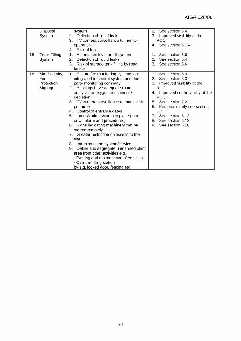
AIGA 028/06
Disposal System
system 2. Detection of liquid leaks 3. TV camera surveillance to monitor
operation 4. Risk of fog
2. See section 5.4 3. Improved visibility at the
ROC 4. See section 5.7.4
15 Truck Filling System
1. Automation level on fill system 2. Detection of liquid leaks 3. Risk of storage tank filling by road
tanker
1. See section 5.6 2. See section 5.4 3. See section 5.6
16 Site Security, Fire Protection, Signage
1. Ensure fire monitoring systems are integrated to control system and third party monitoring company
2. Buildings have adequate room analysis for oxygen enrichment / depletion
3. TV camera surveillance to monitor site perimeter
4. Control of entrance gates 5. Lone Worker system in place (man-
down alarm and procedures) 6. Signs indicating machinery can be
started remotely 7. Greater restriction on access to the
site 8. Intrusion alarm system/service 9. Define and segregate unmanned plant
area from other activities e.g. - Parking and maintenance of vehicles - Cylinder filling station by e.g. locked door, fencing etc
1. See section 5.3 2. See section 5.3 3. Improved visibility at the
ROC 4. Improved controllability at the
ROC 5. See section 7.2 6. Personal safety see section
6.7 7. See section 6.12 8. See section 6.12 9. See section 6.10
20