aii 42479 interior illumination - college hills honda
TRANSCRIPT
© 2009 American Honda Motor Co., Inc. - All Rights Reserved. AII 42479 (0908) 1 of 1308E10-SNA-1000-91
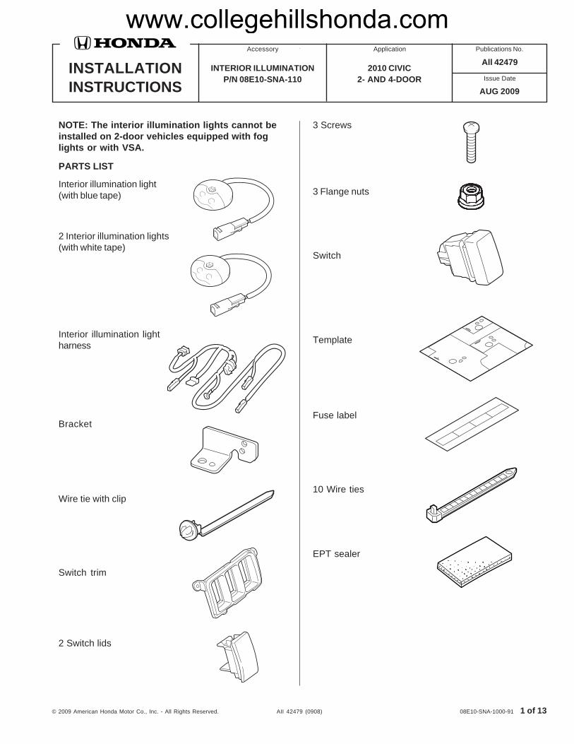
NOTE: The interior illumination lights cannot beinstalled on 2-door vehicles equipped with foglights or with VSA.
PARTS LIST
Interior illumination light(with blue tape)
2 Interior illumination lights(with white tape)
INSTALLATIONINSTRUCTIONS
Accessory Application Publications No.
Issue Date
AUG 2009
2010 CIVIC2- AND 4-DOOR
INTERIOR ILLUMINATIONP/N 08E10-SNA-110
All 42479
Interior illumination lightharness
Wire tie with clip
Bracket
Switch trim
2 Switch lids
3 Screws
3 Flange nuts
Switch
Template
Fuse label
10 Wire ties
EPT sealer
www.collegehillshonda.com

2 of 13 AII 42479 (0908) © 2009 American Honda Motor Co., Inc. - All Rights Reserved.
Illustration of the Interior Illumination LightsInstalled on the Vehicle
TOOLS AND SUPPLIES REQUIREDPhillips screwdriverFlat-tip screwdriverRatchet10 mm SocketDrillDrill bits (3 mm, 5 mm, and 10 mm)FilePushpinUtility knifeScissorsPiece of steel wireElectrical tapeAdhesive tapeEye protection (face shield, safety goggles, etc.)ScaleShop towel
INSTALLATION
Customer Information: The information in thisinstallation instruction is intended for use only byskilled technicians who have the proper tools,equipment, and training to correctly and safely addequipment to your vehicle. These proceduresshould not be attempted by “do-it-yourselfers.”
1. Make sure you have the anti-theft code for theradio, then write down the radio station presets.
2. Disconnect the negative cable from the battery.
4. Remove the driver’s dashboard lower cover (eightclips).
5202121T
DRIVER’SDASHBOARDLOWER COVER
8 CLIPS
3. If equipped, remove the driver’s dashboard undercover (turn the knob counterclockwise, and releasetwo clips and pin).
5202112T
KNOB
DRIVER’SDASHBOARDUNDER COVER
2 CLIPS
PIN
5306010T
FUSE CASE (2A)
INTERIORILLUMINATIONLIGHT(With white tape.)
SWITCH
INTERIORILLUMINATIONLIGHT
(With blue tape.)
INTERIORILLUMINATIONLIGHT(With white tape.)
INTERIOR ILLUMINATIONLIGHT HARNESS
www.collegehillshonda.com
© 2009 American Honda Motor Co., Inc. - All Rights Reserved. AII 42479 (0908) 3 of 13
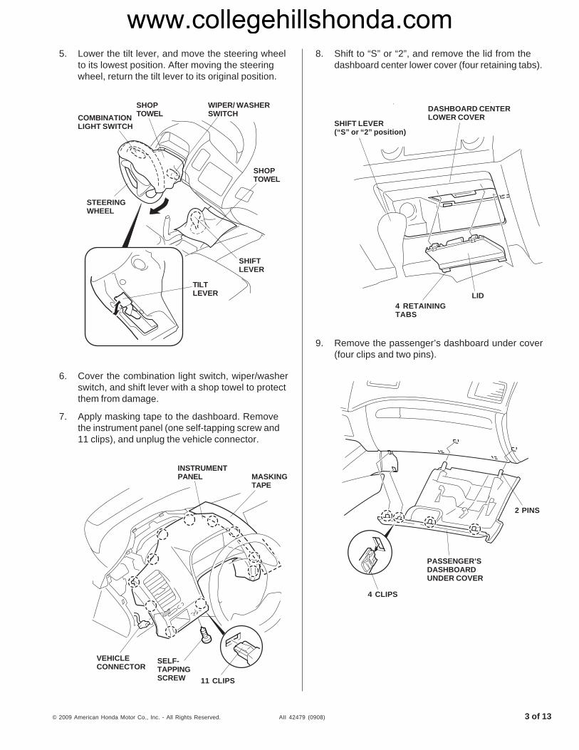
5. Lower the tilt lever, and move the steering wheelto its lowest position. After moving the steeringwheel, return the tilt lever to its original position.
6. Cover the combination light switch, wiper/washerswitch, and shift lever with a shop towel to protectthem from damage.
7. Apply masking tape to the dashboard. Removethe instrument panel (one self-tapping screw and11 clips), and unplug the vehicle connector.
8. Shift to “S” or “2”, and remove the lid from thedashboard center lower cover (four retaining tabs).
9. Remove the passenger’s dashboard under cover(four clips and two pins).
5306360T
4 CLIPS
PASSENGER’SDASHBOARDUNDER COVER
2 PINS
5624100B
INSTRUMENTPANEL
11 CLIPS
SELF-TAPPINGSCREW
VEHICLECONNECTOR
MASKINGTAPE
5202130T
DASHBOARD CENTERLOWER COVER
LID4 RETAININGTABS
SHIFT LEVER(“S” or “2” position)
5306371T
COMBINATIONLIGHT SWITCH
SHOPTOWEL
WIPER/ WASHERSWITCH
STEERINGWHEEL
TILTLEVER
SHOPTOWEL
SHIFTLEVER
www.collegehillshonda.com
4 of 13 AII 42479 (0908) © 2009 American Honda Motor Co., Inc. - All Rights Reserved.
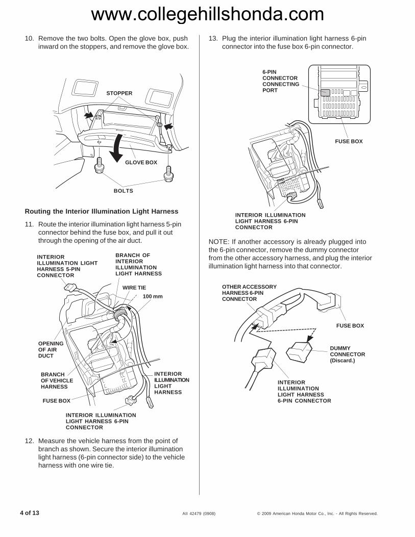
Routing the Interior Illumination Light Harness
11. Route the interior illumination light harness 5-pinconnector behind the fuse box, and pull it outthrough the opening of the air duct.
13. Plug the interior illumination light harness 6-pinconnector into the fuse box 6-pin connector.
5213100T
FUSE BOX
DUMMYCONNECTOR(Discard.)
OTHER ACCESSORYHARNESS 6-PINCONNECTOR
INTERIORILLUMINATIONLIGHT HARNESS6-PIN CONNECTOR
NOTE: If another accessory is already plugged intothe 6-pin connector, remove the dummy connectorfrom the other accessory harness, and plug the interiorillumination light harness into that connector.
10. Remove the two bolts. Open the glove box, pushinward on the stoppers, and remove the glove box.
5306033T
6-PINCONNECTORCONNECTINGPORT
FUSE BOX
INTERIOR ILLUMINATIONLIGHT HARNESS 6-PINCONNECTOR
5306025T
INTERIORILLUMINATION LIGHTHARNESS 5-PINCONNECTOR
WIRE TIE100 mm
INTERIORILLUMINATIONLIGHTHARNESS
INTERIOR ILLUMINATIONLIGHT HARNESS 6-PINCONNECTOR
FUSE BOX
BRANCHOF VEHICLEHARNESS
OPENINGOF AIRDUCT
BRANCH OFINTERIORILLUMINATIONLIGHT HARNESS
12. Measure the vehicle harness from the point ofbranch as shown. Secure the interior illuminationlight harness (6-pin connector side) to the vehicleharness with one wire tie.
5202260T
STOPPER
BOLTS
GLOVE BOX
www.collegehillshonda.com

© 2009 American Honda Motor Co., Inc. - All Rights Reserved. AII 42479 (0908) 5 of 13
14. Route the two interior illumination light harness2-pin connectors onto the right side of thevehicle along the vehicle harness.
15. Attach the 2A fuse label to the interiorillumination light harness fuse case.
16. Remove the ground bolt from the vehicle. Securethe interior illumination light harness groundterminal with the ground bolt you just removed.
5306043T
FUSE LABEL(INTERIORILLUMINATION
LIGHT 2A)
INTERIORILLUMINATIONLIGHT HARNESS2-PINCONNECTORS
GROUNDTERMINAL
INTERIORILLUMINATIONLIGHT HARNESS
FUSE CASE
GROUNDBOLT(Reuse.)
FRONT
17. Route the wire through the opening for the lid ofthe dashboard center lower cover, and wind it ontothe interior illumination light harness 2-pinconnector (long harness side).
5306050T
ELECTRICALTAPE
INTERIOR ILLUMINATIONLIGHT HARNESS 2-PINCONNECTOR
ELECTRICALTAPE
STEEL WIRE
18. Secure the other 2-pin connector to the interiorillumination light harness with electrical tape.
19. Pull the interior illumination light harness out ofthe lid opening of the dashboard center lowercover by pulling the wire.
20. Remove the wire and electrical tape from theinterior illumination light harness.
5306060T
STEEL WIRE
ELECTRICALTAPE
INTERIORILLUMINATIONLIGHT HARNESS
www.collegehillshonda.com

6 of 13 AII 42479 (0908) © 2009 American Honda Motor Co., Inc. - All Rights Reserved.
23. Secure the interior illumination light harness tothe vehicle harness with three wire ties.
24. Secure the interior illumination light harness tothe vehicle harness using four wire ties if thevehicle is equipped with the driver’s dashboardunder cover. Use three wire ties if the vehicle iswithout the driver’s dashboard under cover.
5306090T
VEHICLEHARNESS
WIRE TIES
INTERIORILLUMINATIONLIGHT HARNESS
5306100TWIRETIES
WIRE TIE(Vehicle withdriver’s dashboardunder cover only)
VEHICLEHARNESS
INTERIORILLUMINATIONLIGHT HARNESS
21. Route the interior illumination light harness 2-pinconnector to the passenger’s side along thevehicle harness.
22. Secure the interior illumination light harness to thevehicle harness with two wire ties.
5306070T
OPENING INGLOVE BOX
5306082T
VEHICLEHARNESS WIRE TIE
INTERIORILLUMINATIONLIGHTHARNESS
FUSE BOX
WIRE TIE
INTERIORILLUMINATIONLIGHT HARNESS2-PIN CONNECTOR
www.collegehillshonda.com
© 2009 American Honda Motor Co., Inc. - All Rights Reserved. AII 42479 (0908) 7 of 13
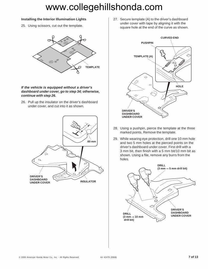
Installing the Interior Illumination Lights
25. Using scissors, cut out the template.
If the vehicle is equipped without a driver’sdashboard under cover, go to step 34; otherwise,continue with step 26.
26. Pull up the insulator on the driver’s dashboardunder cover, and cut into it as shown.
5306120T
DRIVER’SDASHBOARDUNDER COVER INSULATOR
60 mm
5604340T
TEMPLATE
27. Secure template (A) to the driver’s dashboardunder cover with tape by aligning it with thesquare hole at the end of the curve as shown.
28. Using a pushpin, pierce the template at the threemarked points. Remove the template.
29. While wearing eye protection, drill one 10 mm holeand two 5 mm holes at the pierced points on thedriver’s dashboard under cover. First drill with a3 mm bit, then finish with a 5 mm bit/10 mm bit asshown. Using a file, remove any burrs from theholes.
5306140T
DRILL(3 mm 5 mm drill bit)
DRILL(3 mm 10 mmdrill bit)
DRIVER’SDASHBOARDUNDER COVER
5306130T
TEMPLATE (A)
PUSHPIN
CURVED END
DRIVER’SDASHBOARDUNDER COVER
HOLE
www.collegehillshonda.com

8 of 13 AII 42479 (0908) © 2009 American Honda Motor Co., Inc. - All Rights Reserved.
32. Bundle the interior light harness and secure theconnector to the bracket using a wire tie with clip.
33. Reinstall the insulator to the driver’s dashboardunder cover, and pass the interior illumination lightconnector through the slit.
5306171T
INTERIORILLUMINATIONLIGHTCONNECTOR
BRACKET
WIRE TIEWITH CLIP
DRIVER’S DASHBOARDUNDER COVER
5306350T
INSULATOR INTERIORILLUMINATIONLIGHTCONNECTOR
SLITDRIVER’SDASHBOARDUNDER COVER
30. Cut the rib of the driver’s dashboard under coveras shown. Using a file, remove any burrs from theedge.
31. Route one interior illumination light (with whitetape) connector through the 10 mm hole. Installthe interior light and bracket on the driver’sdashboard under cover with a screw and flangenut.
5306160T
FLANGENUT
BRACKET
INTERIORILLUMINATIONLIGHTCONNECTOR
DRIVER’SDASHBOARDUNDERCOVER
SCREWINTERIORILLUMINATIONLIGHT(with white tape)
5306150T
RIB
DRIVER’SDASHBOARDUNDER COVER
www.collegehillshonda.com

© 2009 American Honda Motor Co., Inc. - All Rights Reserved. AII 42479 (0908) 9 of 13
35. Using a pushpin, pierce the template at the threemarked points. Remove the template.
36. While wearing eye protection, drill one 10 mmhole and two 5 mm holes at the pierced points onthe lid. First drill with a 3 mm bit, then finish witha 5 mm bit/10 mm bit as shown. Using a file,remove any burrs from the holes.
5306180T
PUSHPIN
TEMPLATE(B)
LID OFDASHBOARDCENTERLOWER COVER
5306190T
DRILL(3 mm 5 mm drill bit)
DRILL(3 mm 10 mmdrill bit)
LID
34. Position template (B) on the lid of the dashboardcenter lower cover.
37. Route the interior illumination light (with blue tape)connector through the 10 mm hole. Install thecourtesy light on the lid with the screw and flangenut.
40. Using a pushpin, pierce the template at the threemarked points. Remove the template.
5306220T
PUSHPIN CURVEDEND
HOLE
PASSENGER’SDASHBOARDUNDER COVER
TEMPLATE(C)
39. Secure template (C) to the passenger’s dashboardunder cover with tape by aligning it with the squarehole and the end of the curve as shown. Do notuse the marks on the inside of the passenger’sdashboard under cover.
38. Using scissors, cut one EPT sealer into threeequal pieces and use one of the pieces to wraparound the interior illumination light connector.
5306200T
INTERIORLIGHTCONNECTOR
FLANGENUT
LID
INTERIORLIGHT(with bluetape)
SCREW
EPTSEALER(1/3)
www.collegehillshonda.com
10 of 13 AII 42479 (0908) © 2009 American Honda Motor Co., Inc. - All Rights Reserved.
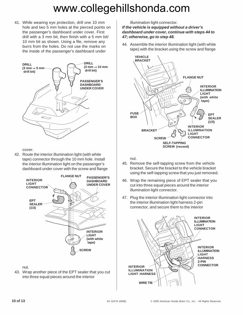
illumination light connector.If the vehicle is equipped without a driver’sdashboard under cover, continue with steps 44 to47; otherwise, go to step 48.
44. Assemble the interior illumination light (with whitetape) with the bracket using the screw and flange
nut.45. Remove the self-tapping screw from the vehicle
bracket. Secure the bracket to the vehicle bracketusing the self-tapping screw that you just removed.
46. Wrap the remaining piece of EPT sealer that youcut into three equal pieces around the interiorillumination light connector.
47. Plug the interior illumination light connector intothe interior illumination light harness 2-pinconnector, and secure them to the interior
41. While wearing eye protection, drill one 10 mmhole and two 5 mm holes at the pierced points onthe passenger’s dashboard under cover. Firstdrill with a 3 mm bit, then finish with a 5 mm bit/10 mm bit as shown. Using a file, remove anyburrs from the holes. Do not use the marks onthe inside of the passenger’s dashboard under
5306230T
PASSENGER’SDASHBOARDUNDER COVER
DRILL(3 mm 5 mmdrill bit)
DRILL(3 mm 10 mmdrill bit)
cover.42. Route the interior illumination light (with white
tape) connector through the 10 mm hole. Installthe interior illumination light on the passenger’sdashboard under cover with the screw and flange
nut.43. Wrap another piece of the EPT sealer that you cut
into three equal pieces around the interior
5306241T
PASSENGER’SDASHBOARDUNDER COVER
FLANGE NUTINTERIORLIGHTCONNECTOR
EPTSEALER(1/3)
INTERIORLIGHT(with whitetape)
SCREW
5306303T
INTERIORILLUMINATIONLIGHTHARNESS2-PINCONNECTORINTERIOR
ILLUMINATIONLIGHT HARNESS
WIRE TIE
INTERIORILLUMINATIONLIGHTCONNECTOR
5306252T
VEHICLEBRACKET
FUSEBOX
BRACKET
SCREWSELF-TAPPINGSCREW (reused)
INTERIORILLUMINATIONLIGHTCONNECTOR
EPTSEALER(1/3)
FLANGE NUT
INTERIORILLUMINATIONLIGHT(with whitetape)
www.collegehillshonda.com

© 2009 American Honda Motor Co., Inc. - All Rights Reserved. AII 42479 (0908) 11 of 13
illumination light harness using a wire tie.If the vehicle is equipped with a instrument panelpocket, continue with step 48; otherwise, go tostep 51.
48. Remove the pocket from the instrument panel
(three self-tapping screws).49. Install the switch trim to the instrument panel
5306271T
SELF-TAPPINGSCREWS(reused) INSTRUMENT
PANEL
SWITCH
SWITCHLID
SWITCHTRIM
5306260T
SELF-TAPPINGSCREWS
POCKET(Discard.)
INSTRUMENTPANEL
with the three self-tapping screws.50. Install the switch and two switch lids to the
51. Remove the switch lid from the instrument panel.52. Install the switch in the instrument panel.
53. Plug the interior illumination light harness 5-pinconnector to the switch, and reinstall the
5306330T
INSTRUMENTPANEL
SWITCH
SWITCH LID(Discard.)
5306281T
INTERIORILLUMINATIONLIGHT HARNESS5-PINCONNECTOR
SWITCH
INSTRUMENTPANEL
instrument panel.54. Reinstall the driver’s dashboard lower cover and
switch trim. Go to step 53.
www.collegehillshonda.com

12 of 13 AII 42479 (0908) © 2009 American Honda Motor Co., Inc. - All Rights Reserved.
cover, and reinstall the lid.57. Plug the interior illumination light harness 2-pin
connector to the interior illumination light connectoron the passenger’s dashboard under cover, and
5306291T
INTERIORILLUMINATIONLIGHTHARNESS2-PINCONNECTOR
INTERIORILLUMINATIONLIGHTCONNECTOR
DRIVER’SDASHBOARDUNDER COVER
5306310TLID
DASHBOARD CENTERLOWER COVER
INTERIORILLUMINATIONLIGHTCONNECTOR
INTERIORILLUMINATIONLIGHT HARNESS2-PINCONNECTOR
and reinstall the under cover.56. Plug the interior illumination light harness 2-pin
connector to the interior illumination lightconnector on the lid of the dashboard center lower
glove box.55. If equipped with the driver’s dashboard under
cover, plug the interior illumination light harness 2-pin connector to the interior illumination lightconnector on the driver’s dashboard under cover,
5306321TPASSENGER’S DASHBOARDUNDER COVER
INTERIORILLUMINATIONLIGHTCONNECTOR
INTERIOR ILLUMINATIONLIGHT HARNESS 2-PINCONNECTOR
www.collegehillshonda.com

© 2009 American Honda Motor Co., Inc. - All Rights Reserved. AII 42479 (0908) 13 of 13
reinstall the under cover.58. Check that all wire harnesses are routed
properly and all connectors are plugged in.
59. Reinstall all removed parts. Check that all clipsand other fasteners are installed securely.
60. Reconnect the negative cable to the battery.
61. Enter the customer’s radio anti-theft code, andreset the radio station presets.
62. Reset the clock.
NOTE: When the battery is disconnected, the driver’swindow auto up/down function is disabled.
• Start the engine. Push down on the driver’swindow switch until the window is fully open.
• Pull up on the driver’s window switch to closethe window completely, then hold the switch fortwo seconds or more.
• Lower and raise the driver’s window to check theoperation of the driver’s window auto up/downfunction.
5306340T
HEADLIGHT SWITCH
-CO
UR
TES
YLI
GH
TS
WIT
CH ON - ON ON
- -OFF
OFF
HOW TO OPERATE
• Turn the headlight switch to the “ ” and “ ”position (headlights on low beam).
• Press the courtesy light switch.
www.collegehillshonda.com