air accident investigation sector - general civil aviation ... · manufacturer) and turbomeca...
TRANSCRIPT

Air Accident Investigation Sector
Accident
- Final Report -
AAI Case No: AIFN/0002/2014
Loss of Control Inflight (LOC-I)
Operator Helidubai
Make and Model Airbus EC-130B4
Nationality and Registration United Arab Emirates, A6-DYR
Place of Occurrence Dubai, UAE
State of Occurrence United Arab Emirates
Date of Occurrence 22 January 2014

Accident Investigation Final Report No AIFN/0002/2014, issued on 28 December 2016 i
Air Accident Investigation Sector General Civil Aviation Authority
The United Arab Emirates
Occurrence Brief
Investigation Objective This Investigation is performed pursuant to the UAE Federal Act No. 20 of 1991,
promulgating the Civil Aviation Law, Chapter VII- Aircraft Accidents, Article 4. It is in compliance with the UAE Civil Aviation Regulations, Part VI, Chapter 3, in conformity with Annex 13 to the Convention on International Civil Aviation, and in adherence to the Air Accidents and Incidents Investigation Manual.
The sole objective of this Investigation is to prevent aircraft accidents and incidents. It is NOT the purpose of this activity to apportion blame or liability.
Investigation Process The Accident was notified to the Duty Investigator (DI) of the Air Accident
Investigation Sector (AAIS) of the United Arab Emirates (UAE) on 22 January 2014 at about 1145UTC. An Investigation Team was immediately deployed to the Accident site.
The Team coordinated with all authorities on site by initiating the Accident investigation process according to prepared and previously exercised plans.
In accordance with Annex 13, the Bureau d'Enquêtes et d'Analyses pour la sécurité de l'aviation civile (BEA) was notified and appointed an Accredited Representative to the investigation and appointed Technical Advisers from Airbus Helicopters (airframe manufacturer) and Turbomeca (engine manufacturer).
The AAIS led the investigation, as the UAE was the State of Occurrence.
Notes:
1 Whenever the following words are mentioned in this Report with the first letter Capitalized, it shall mean:
- (Aircraft)- the helicopter involved in this accident
GCAA AAI Report Number AFIN/0020/2014
Occurrence classification Accident
Occurrence Categorization Loss of Control Inflight/LOC-I
Operator Helidubai
Aircraft Type and Registration Airbus EC-130B4/A6-DYR
MSN 3990
No. and Type of Engines One, Turbomeca Turbo Shaft Arriel 2B1
Location Dubai
Date and Time (UTC) 22/01/2014, 1132:21
Type of Flight Commercial (Air Transport)
Persons On-board Two
Injuries Serious

Accident Investigation Final Report No AIFN/0002/2014, issued on 28 December 2016 ii
- (Investigation)- the investigation into this accident
- (Accident)- this accident that is the subject of this report
- (Operator)- Helidubai as the operator of the aircraft
- (Report)- this accident investigation Final Report
- (Pilot)- the pilot of the accident flight.
2 Unless otherwise mentioned, all times in this Report are given in 24-hour clock in Coordinated Universal Time (UTC), (UAE Local Time minus 4 hours).
3 Photos and associated images used in this Report are taken from different sources and are adjusted from the original for the sole purpose of improving the clarity of the Report. Modifications to images used in this Report are limited to cropping, magnification, file compression, or enhancement of color, brightness, contrast or insertion of text boxes, arrows or lines.
Accident Investigation Final Report No AIFN/0002/2014, issued on 28 December 2016 iii
Abbreviations AAIS Air Accident Investigation Sector
ADREP Accident/Incident Data Reporting
AGL Above ground level
ALSE Aviation life support equipment
AOC Air operators certificate
ATO Approved training organization
CEO Chief Executive Officer
CISM Critical incident stress management
CPACIRS Crash Protected Aircraft Cockpit Image Recorder Systems
CVR Cockpit voice recorder
DAW Dubai Air Wing
DXB Dubai International Airport
EECU Electronic engine control unit
ELT Emergency locator transmitter
EOL Engine over limit
ERP Emergency response plan
FADEC Full authority digital engine control
FATO Final approach and takeoff
FM Flight manual
FOB Fixed operating base
GCAA General Civil Aviation Authority
HFACS Human factors analysis and classification system
HLO Helicopter Landing Officer
ICAO International Civil Aviation Organization
LTE Loss of tail rotor effectiveness
MCC Mission coordination center
OEM Original equipment manufacturer
OPC Operator proficiency check
PH Post Holder
RFM Rotorcraft flight manual
ROD Rate of descent
SAR Search and rescue
SDCPS Safety data collection and processing system
SMS Safety management system
SSA Sound spectrum analysis
UA Unusual attitude

Accident Investigation Final Report No AIFN/0002/2014, issued on 28 December 2016 iv
UAE The United Arab Emirates
UTC Universal Time Coordinated
VEMD Vehicle and engine multifunction display
WDI Wind direction indicator
ZATL Heliport designation

Accident Investigation Final Report No AIFN/0002/2014, issued on 28 December 2016 v
Synopsis On 22 January 2014, an Airbus Helicopters EC-130B4 Aircraft, registration A6-DYR,
operated by Helidubai impacted the heliport during departure to Dubai International Airport (OMDB) from the Atlantis Palm hotel heliport.
The Aircraft had operated six passenger tourist flights over Dubai prior to the positioning flight from the Atlantic Palm heliport to the Dubai Air Wing fixed operating base (FOB) at OMDB. The final flight of each day was a positioning flight from the heliport to the Operator’s FOB at OMDB.
The departure was normally a coastal departure along the Palm, inbound to OMDB. The flight required lifting to a hover position, a pedal turn to a northerly heading, and a standard climbing departure from the heliport. The Aircraft was airborne at 1132:21 UTC for the 15-minute positioning flight.
On lift-off, the Pilot simultaneously pulled power into the climb while applying continuous left pedal, turning the Aircraft counter clockwise (to the left). This turn continued past the optimal northerly heading for departure, with the Aircraft turning rapidly counter clockwise.
The turn rate accelerated, increasing to approximately 180° per second at a height of approximately 22 meters (72 feet) above the heliport.
The Aircraft then descended rapidly, pitching forward, while continuing in a counter clockwise turn prior until impact with the heliport. The Aircraft impacted the heliport vertically, with a level attitude, minimal forward speed, with approximately 5° nose down attitude and a rapid rate of descent (ROD), until impact.
The Air Accident Investigation Sector (AAIS) determines that the causes of the Accident were intentional entry into a continuous left hand pedal turn, which rapidly increased the rotation rate of the Aircraft leading to an unstable condition developing outside of the Pilot’s ability to respond, resulting in a loss of control in-flight (LOC-I) and impact with the heliport. The Pilot was in a spatial disorientation resulting from the rapid onset of the yaw/high speed rotation combined with the effects of the rotational inertia forcing the Pilot and HLO forward. The Pilot was unable to determine the cause of the induced turn rate and apply the corrective actions necessary to return to a stable, steady state condition. The Pilot lowered the collective resulting in an uncontrolled descent onto the heliport.
This Final Report contains 10 safety recommendations: three are addresses to Helidubai (the Operator); five to the General Civil Aviation Authority (GCAA) of the United Arab Emirates (authority of the State of Registry and State of the Operator, and authority responsible for the aerodromes certification and oversight in the United Arab Emirates); and two to the European Aviation Safety Agency (EASA ‘authority of Aircraft design’).

Accident Investigation Final Report No AIFN/0002/2014, issued on 28 December 2016 vi
Contents Occurrence Brief .................................................................................................................... i Investigation Process ............................................................................................................. i Abbreviations ........................................................................................................................ iii Synopsis ............................................................................................................................... v Contents .............................................................................................................................. vi 1. Factual Information ........................................................................................................ 1
History of the Flight ................................................................................................. 1 Injuries to Persons .................................................................................................. 3 Damage to the Aircraft ............................................................................................ 3
1.3.1 Damage to the rotor, Fenestron and skids ..................................................... 4 Other Damage ........................................................................................................ 5 Personnel Information ............................................................................................. 5
1.5.1 The Pilot ........................................................................................................ 5 1.5.2 The Helicopter Landing Officer (HLO) ............................................................ 5
Aircraft Information ................................................................................................. 5 1.6.1 Airworthiness ................................................................................................. 5 1.6.2 Aircraft general data ...................................................................................... 6 1.6.3 Engine ........................................................................................................... 7 1.6.4 The VEMD ..................................................................................................... 7 1.6.5. Tail rotor ....................................................................................................... 7 1.6.6 Fenestron fan assembly ................................................................................. 8 1.6.7 Tail rotor drive system.................................................................................... 8 1.6.8 Seatbelts/inertia reel description .................................................................... 9 1.6.9 Fuel tank ...................................................................................................... 10 1.6.10 Fuel tank drain valve .................................................................................. 10
1.7 Meteorological Information .................................................................................... 10 1.8 Aids to Navigation ................................................................................................. 11 1.9 Communications ................................................................................................... 12
1.9.1 International COSPAS-SARSAT satellite network ........................................ 12 1.9.2 Emergency locator transmitter (ELT) ........................................................... 12 1.9.3 National Rescue Coordination Center (NRCC), United Arab Emirates ......... 13
1.10 Aerodrome Information ........................................................................................ 13 1.11 Flight Recorders .................................................................................................. 14 1.12 Wreckage and Impact Information ....................................................................... 14
1.12.1 Debris mapping .......................................................................................... 14 1.12.2 Damage to firefighting equipment and adjacent structure .......................... 15
1.13 Medical and Pathological Information................................................................... 16 1.13.1 Crew .......................................................................................................... 16 1.13.2 Alcohol and drugs testing ........................................................................... 16
1.14 Fire ...................................................................................................................... 16 1.15 Survival Aspects .................................................................................................. 16
1.15.1 The onboard ELT ....................................................................................... 16 1.15.2 Dynamic load transfer ................................................................................ 16 1.15.3 EASA certification: Emergency landing conditions ..................................... 17 1.15.4 Crew and passenger seating certification................................................... 17
1.16 Tests and Research ............................................................................................. 18 1.16.1 Test flight – tail rotor control effectiveness/Fenestron audio recording ....... 18 1.16.2 Acoustic analysis – accident video ............................................................. 18 1.16.3 Vehicle and engine multifunction display (VEMD) ...................................... 19

Accident Investigation Final Report No AIFN/0002/2014, issued on 28 December 2016 vii
1.16.4 Airbus Helicopters investigation report EAI N° 09/2014 MM ....................... 19 1.16.5 Shoulder harness inertia reel function check .............................................. 19 1.16.6 ELT function and verification testing .......................................................... 20
1.17 Organizational and Management Information ....................................................... 20 1.17.1 The Operator’s safety management system (SMS) .................................... 21 1.17.2 Operator operational/training/safety management ..................................... 21 1.17.3 Emergency response plan (ERP) ............................................................... 22 1.17.4 Safety management system (SMS) Heliports .......................................... 22
1.18 Additional Information .......................................................................................... 22 1.18.1 Aircraft reference planes and axes/datum .................................................. 22 1.18.2 Airbus helicopter’s Flight Manual – EC130-B4/ Limitations ........................ 22 1.18.3 Eurocopter Letter Service No. 1673-67-04/ SUBJECT Reminder concerning the YAW axis control for all helicopters in some flight conditions ........ 23 1.18.4 Helicopter blade coning angle .................................................................... 23 1.18.5 Vehicle and engine multifunction display flight report page ..................... 24 1.18.6 Hover and low airspeed stability, control, and flying qualities ..................... 25 1.18.7 Rotary wing stability and control ................................................................ 26 1.18.8 Yaw rate limitations for the EC130-B4 ....................................................... 26 1.18.9 Anecdotal evidence from witness statements ............................................ 27 1.18.10 Civil Aviation Regulations (CAR), Part III, Chapter 2 ................................ 27 1.18.11 Requirements for in-flight data recording ................................................. 27
1.19 Useful or Effective Investigation Techniques ........................................................ 28 1.19.1 Video tracking and accident reconstruction animation................................ 28 1.19.2 Sound spectrum analysis (SSA) ................................................................ 29 1.19.3 Human factors analysis and classification system (HFACS) ...................... 29
2 Analysis ....................................................................................................................... 31 2.1 General
Accident Sequence – Phase One ......................................................................... 31 2.3 Event Sequence Parameters ................................................................................ 37 2.4 Rotor Disk Conning ............................................................................................... 38 2.5 Accident Sequence - Phase Two .......................................................................... 38
2.5.1 Uncontrolled ground rotation ........................................................................ 38 2.5.2 Debris distribution and Aircraft movement.................................................... 39
2.6 Shoulder Harness Inertia Reel Locking Mechanism, High Rotational rates, Rotational Inertia and Pilot Body Position During the Accident Sequence .................... 39 2.7 Estimated Wind Speed and Direction at the Heliport ............................................. 41 2.8 Fenestron Tail Rotor Failure Analysis ................................................................... 41
2.8.1 Photo/video analysis ................................................................................... 41 2.8.2 CCTV image capture of the Fenestron immediately following impact .......... 42 2.8.3 Damage to the Fenestron rotating parts and the drive shaft torque tube connection ............................................................................................................ 42
2.9 Acoustic/Sound Spectrum Analysis – Accident Video ........................................... 43 2.10 Loss of Tail Rotor Effectiveness (LTE) ................................................................. 43
2.10.1 Review of previous accident investigations involving LTE .......................... 43 2.11 Abnormal Attitude Recovery ................................................................................ 44
2.11.1 Safety information ...................................................................................... 44 2.12 Vehicle and Engine Multifunction Display (VEMD) ............................................... 44 2.13 Emergency Locator Transmitter (ELT) Signal ...................................................... 45
2.13.1 KANNAD 406 AF-H emergency locator transmitter .................................... 45 2.13.2 Programming dongle.................................................................................. 45
2.14 Fuel Drain Location .............................................................................................. 46

Accident Investigation Final Report No AIFN/0002/2014, issued on 28 December 2016 viii
2.15 Safety Management System (SMS) ..................................................................... 46 2.15.1 Risk assessment ........................................................................................ 46
2.16 Human Factors Analysis ...................................................................................... 46 3 Conclusions ................................................................................................................. 48
3.1 General ................................................................................................................. 48 3.2 Findings ................................................................................................................ 48 3.3 Causes ................................................................................................................. 49 3.4 Contributing Factors .............................................................................................. 49
4 Safety Recommendations ............................................................................................ 50 4.1 General ................................................................................................................. 50 4.2 Safety Actions Taken ............................................................................................ 50
4.2.1 Safety actions taken by Helidubai ................................................................ 50 4.2.2 Safety Actions taken by Alpha Tours/Palm Atlantis ...................................... 51 4.2.3 Safety Actions taken by the European Aviation Safety Agency (EASA) ....... 51
4.3 Final Report Safety Recommendations ................................................................. 51 4.3.1 Helidubai ..................................................................................................... 51 4.3.2 Alpha Tours .................................................... Error! Bookmark not defined. 4.3.3 Atlantis the Palm hotel (heliport owner) ........................................................ 52 4.3.4 EASA ........................................................................................................... 52 4.3.5 The General Civil Aviation Authority (GCAA) of the United Arab Emirates ... 51
List of tables:
Table 1. Injuries to persons Table 2. Pilot information Table 3. Aircraft general data
List of figures:
Figure 1. Rapid descent prior to impact Figure 2. Aircraft on the heliport Figure 3. Lower fuselage damage Figure 4. Aircraft damage viewed from the rear of the helicopter Figure 5. Airbus Helicopters EC130-B4 Figure 6. EC130-B4 general information Figure 7. Rotor assembly viewed from the right hand and an exemplar Fenestron view Figure 8. Tail rotor drive system Figure 9. Four-point harness gap Figure 10. Fuel system schematic Figure 11. Fuel tank water drain valve Figure 12. Aircraft orientation and location of the WDI Figure 13. COSPAS-SARSAT Figure 14. Heliport at Palm Atlantis (ZATL) Figure 15. (Left) heliport contact witness marks. (Right) view south, Down the Heliport
centerline from the initial impact site. Figure 16. Aircraft immediately following heliport impact Figure 17. Debris pattern and component locations Figure 18. Pilots seat deformation/structural failure Figure 19. Seat fuse and structural deformation Figure 2. Tail rotor turn rate/audio recording test Figure 3 Acoustic analysis (Section 2 Analysis) Figure 4. Helidubai structure organization Figure 5. The Operator’s fleet size
Accident Investigation Final Report No AIFN/0002/2014, issued on 28 December 2016 ix
Figure 6. Aircraft reference planes, axes, datum Figure 7. Flight manual limitation – aerobatics Figure 8. Rotor blade coning angle blade force resolution Figure 9. Longitudinal tilt coning angle Figure 28. VEMD screen capture Figure 29. Helicopter control of yaw diagram Figure 30. Flight manual/AS350-B3: Hover rotation limitation Figure 31. Object tracking software to determine the Aircraft movement sequencing Figure 32. Animation of Pilot’s perspective Figure 33. Key to the video/animation sequence Figure 34. Yaw rate Figure 35. Maximum height above the ground Figure 36. Aircraft dynamic condition at point of impact Figure 37. Combined flight parameters Figure 38. Rotor tip path plane and rotor disk conning Figure 39. CCTV image of the Aircraft movement on the heliport Figure 40. Throttle position was in ‘Flight’ Setting Figure 41. Composite of the CCTV photos Figure 42. Pilot’s body position at the 8-second mark Figure 43. Pilot’s forward inclined body position Figure 44. Pilot’s forward inclined body position and cyclic control deformation Figure 45. Wind strength and direction Figure 46. Wind direction indicator (WDI) Figure 47. Fenestron shroud damage immediately following the impact Figure 48. Fenestron and torque tube damage Figure 49. VEMD screen capture of the Accident

Accident Investigation Final Report No AIFN/0002/2014, issued on 28 December 2016 1
1. Factual Information History of the Flight1
On 22 January 2014, an Airbus Helicopters EC-130B4 Aircraft, registration A6-DYR, operated by Helidubai impacted the heliport during departure to Dubai International Airport (OMDB) from the Atlantis Palm hotel heliport.
The Aircraft had operated six passenger tourist flights over Dubai prior to the positioning flight from the Atlantic Palm heliport to the Dubai Air Wing fixed operating base (FOB) at OMDB. The final flight of each day was a positioning flight from the heliport to the Operator’s FOB at OMDB.
The flight was operated without passengers; onboard were the handling Pilot and the Helicopter Landing Officer (HLO)2.
The Aircraft was positioned on the heliport aligned on a heading of approximately 200°.
The departure was normally a coastal departure along the Palm, inbound to OMDB. The flight required lifting to a hover position, a pedal turn to a northerly heading and a standard climbing departure from the heliport. The Aircraft was airborne at 1132:21 UTC for the 15-minute positioning flight.
On lift-off, the Pilot simultaneously pulled power into the climb while applying continuous left pedal, turning the Aircraft counter clockwise (to the left).
This turn continued past the optimal northerly heading for departure, with the Aircraft turning rapidly counter clockwise.
The turn rate accelerated, increasing to approximately 180° per second at a height of approximately 22 meters (72 feet) above the heliport.
The Aircraft then descended rapidly, pitching forward, while continuing in a counter clockwise turn prior until impact with the heliport.
The Aircraft impacted the heliport vertically, with a level attitude, minimal forward speed, with approximately 5° nose down attitude and a rapid rate of descent (ROD), until impact.
1 Key events in the Accident timeline:
1. 1532:21 (UAE LT): Lift-off from the Heliport 2. 1532:33 : Loss of control and impact with the heliport 3. 1537:19 : Full stop position. Engine Stop. 4. 1538:00 and onwards: Pilot and passenger extraction/recovery Consider including the timeline in the body of the History of the Flight.
2 The HLO is responsible for the aircraft ramp handling on the heliport.
Figure 1. Rapid descent prior to impact

Accident Investigation Final Report No AIFN/0002/2014, issued on 28 December 2016 2
Following the impact with the heliport landing area, the skids3 failed under the vertical load remaining attached to the airframe for the duration of the ground rotation phase, however they were splayed outwards with the area of the fuselage under the Aircraft between the skids in constant contact with the heliport surface. There was a fuel drain decanting sump with a water drain valve located in this area.4
Due to the hard landing, the main rotor blade tips contacted the heliport and the surrounding terrain damaging the rotor blade tips.
The seat deceleration absorption system was triggered in the early stage of the overload. The deformation is dependent on the energy absorbed. The induced loads on the occupants, the primary and secondary structure, and the dynamic components due to the vertical deceleration was high5.
The Pilot and HLO were both incapacitated from injuries resulting from the combination of the rapid vertical deceleration and that both crewmembers were unrestrained by their shoulder harnesses due to the crew seats lowering as the seats deformed under the load.
The forward doors opened due to the deformation of the Aircraft structure caused by the impact loads. The right hand door separated from the structure, the left hand door deformed allowing the door to open while remaining attached to the structure.
The Pilot, partially restrained by the waist harness, and due to the seat lowering as the seat had lowered as designed due to impact load, was in a forward inclined position with the upper torso and head outside of the cockpit as the Aircraft rotated.
A loss of the Fenestron tail rotor control effectiveness occurred after the Aircraft impacted the heliport when the Fenestron tail assembly was damaged.
With the engine throttle control set to the ‘Flight’ indent position and with some pitch on the main rotor blades, the engine continued to develop power and torque.
As the Aircraft was engaged in a counter clockwise rotation following the hard landing and the Aircraft was under power, it began an uncontrolled rapid counter clockwise rotation.
The Aircraft remained on the heliport with the engine running with the damaged rotor blades turning while the Aircraft was moving along the heliport extended centerline6.
The rotor blades, significantly damaged from the initial impact, contacted a row of trees adjacent to the heliport border causing further damage. The resulting blade imbalance caused severe vibration as the throttle remained at the Flight indent position7.
The tail rotor and the aft tail boom assembly separated from the tail boom early in the ground rotation phase, following numerous collisions with curb structures adjacent to the heliport.
The Aircraft rotated approximately 50 times on the heliport prior to contacting a drainage curb at the edge of the heliport which arrested the rotation and stopped the Aircraft from moving further. The Aircraft remained in that position with the engine running and the damaged rotor blades turning.
3 Skids are the tubular frames on either side of the helicopter that act as the landing gear. 4 The fuel tank is located in the body structure beneath the transmission deck and is equipped with a fuel level transmitter.
The tank also includes a starting priming pump and a decanting sump with a water drain valve. 5 The deformation is dependent on the energy absorbed due to the couple of the Nz and the Aircraft mass. 6 The extended centerline is the area that runs from the heliport to the edge of the heliport, approximately 120 meters from
the impact point. 7 During flight, the twist grip throttle on the Aircraft was positioned in the flight detent position, where the Electronic Engine
Control Unit (EECU), and Full Authority Digital Engine Control (FADEC), control engine rpm.

Accident Investigation Final Report No AIFN/0002/2014, issued on 28 December 2016 3
The heliport ground crew were then able to shut down the engine and assist with removal of the incapacitated crew.
There was significant fuel loss from the fuel tank water drain valve, which was damaged following the hard landing, which had dispersed around the Aircraft.
There was no post-impact fire.
Figure 2. Aircraft on the heliport
Injuries to Persons
The Pilot and the HLO sustained serious injuries resulting from the heliport impact and were transported to a hospital from the Accident site.
Table 1. Injuries to persons
Injuries Flight crew Cabin crew Other crew
onboard Passengers Total onboard Others
Fatal 0 0 0 0 0 0
Serious 2 0 0 0 2 0
Minor 0 0 0 0 0 0
None 0 0 0 0 0 0
TOTAL 2 0 0 0 2 0
Damage to the Aircraft
The Aircraft was significantly damaged due to the heliport impact and subsequent uncontrolled ground rotation.
The airframe was removed from the site relatively intact to a secure storage area for further investigation analysis.

Accident Investigation Final Report No AIFN/0002/2014, issued on 28 December 2016 4
Figure 3. Lower fuselage damage
1.3.1 Damage to the rotor, Fenestron and skids
The left side uncontrolled rotation of the Aircraft down the heliport resulted from the incapacitation of the Pilot, and the subsequent high speed rotation was a consequence of the throttle being left in the ‘Flight’ position, with a collective input.
With the throttle in the ‘Flight’ position, the engine fuel control continued to deliver the demanded power setting as the Aircraft rotated down the heliport contacting various structures, trees, and equipment.
The damage to the Aircraft resulted from the uncontrolled rotation down the heliport and the numerous contact with surrounding structures, flora, and terrain.
Splayed Skids
Lower Fuselage Damage
Figure 4. Aircraft damage viewed from the rear of the helicopter

Accident Investigation Final Report No AIFN/0002/2014, issued on 28 December 2016 5
Other Damage
Damage occurred to the heliport, the surrounding elevated terrain and the firefighting equipment adjacent to the heliport.
Extensive damage was caused to the flora and the curbing along the extended centerline of the heliport.
Personnel Information
1.5.1 The Pilot
The Pilot was licensed and qualified for the flight in accordance with the Civil Aviation Regulations of the United Arab Emirates.
Table 2. Pilot information
Age 39
Type of License CPL (H)
Valid to 23-02-2021
Rating(s) EC130-B4
Total time 2425
Total on type 276.5
Total last 30 days 102
Total on type last 30 days 33
Total last 7 days 16.4
Total on type last 7 days 16.4
Total last 24 hours 4.5
Total on type last 24 hours 4.5
Medical class 1
The Pilot was also licensed and qualified for AS350 type rating in accordance with
the Civil Aviation Regulations of the United Arab Emirates, which was approved by the GCAA.
The Pilot had resigned from the company and was in the process of working the required notice period prior to departing the UAE.
1.5.2 The Helicopter Landing Officer (HLO)
The HLO was located at the heliport for the duration of the flying operations, normally from mid-morning until late afternoon.
On the day of the Accident, the HLO was a passenger, taking the forward right hand seat for the positioning flight to the Helidubai operating base at OMDB.
Aircraft Information
1.6.1 Airworthiness
The Aircraft was airworthy at the time of the Accident. The structural and systems evaluation of the airframe and systems architecture did not indicate any pre-existing failures prior to the impact with the heliport.

Accident Investigation Final Report No AIFN/0002/2014, issued on 28 December 2016 6
1.6.2 Aircraft general data
Table 3. Aircraft general data
Aircraft manufacturer Airbus Helicopters
Model EC 130-B4
MSN 3990
Date of Manufacture 2005
Nationality/Registration UAE/A6-DYR
Owner Helidubai
Operator Helidubai
Certificate of Airworthiness UAE-COA-0132
Valid to 24 March 2014
Certificate of Registration UAE-COR-0449
Valid to Issued on 24 March 2014
Engine Turbomeca Turbo Shaft Arriel 2B1
The Aircraft was manufactured by Eurocopter, and certified as Eurocopter Airbus
Helicopters EC130-B4. The name of the manufacturer (Eurocopter) was changed to Airbus Helicopters in 2014.
Figure 5. Airbus Helicopters EC130-B4
Figure 6 illustrates a simplified reference drawing of the main components.

Accident Investigation Final Report No AIFN/0002/2014, issued on 28 December 2016 7
Figure 6. EC130-B4 general information
The Fenestron fan is the engine driven ducted fan at the end of the tail boom. This ducted fan controls the direction the helicopter is pointing.
A Fenestron is the protected tail rotor of a helicopter operating like a ducted fan.
The housing is integral with the tail skin and, like the conventional tail rotor it replaces, is intended to counteract the torque of the main rotor. It was first developed by the French company Sud Aviation (now part of Airbus Helicopters) and is installed on many of their helicopters.
1.6.3 Engine
The Aircraft was powered by one Turbomeca Arriel 2B1 Turboshaft engine. Examination of the engine did not indicate any pre-existing faults.
The Vehicle and Engine Management Display (VEMD) indicated that the engine was rotating and delivering power at the time of the event.
All of the appropriate documentation concerning the Aircraft airworthiness relating to the engine has been verified.
1.6.4 The VEMD
The VEMD displays the engine and aircraft parameters to pilots. It replaces the conventional indicators and presents the information of the engine controls, fuel controls, and electrical generation. It also includes some further functions: engine health control, cycle recording, failures, and over limits.
1.6.5. Tail rotor
The tail rotor is a shrouded type (Fenestron fan assembly), and is housed in the vertical fin, it comprises ten blades. The blades rotate counter clockwise when viewed from the right hand side of the aircraft.

Accident Investigation Final Report No AIFN/0002/2014, issued on 28 December 2016 8
1.6.6 Fenestron fan assembly
A Fenestron fan assembly is contained in the tail rotor of the helicopter where the propulsive ducted fan is shrouded in a circular duct housing.
The housing is an integral assembly with the tail skin and, like a conventional tail rotor, the function is to counteract the torque of the main rotor.
Figure 7. Rotor assembly. Viewed from the right hand side an exemplar Fenestron view
The control of the Fenestron by the pilot is through the use of conventional floor mounted pedals for directional control and slip/skid control coordination.
1.6.7 Tail rotor drive system
Power is transmitted to the Fenestron fan assembly through an engine driven drive shaft.
Tail Rotor Drive System Description:
Type of tail rotor: Fenestron
Rotor diameter: 1000 mm (39.37 inches)
Direction of rotation advancing blade downwards
Speed of rotation: 3568 rpm
Power: 3400 N (764.3 lbf)
Weight with blades installed: 8.484 kg (18.69 lb).
The shafts are connected to each other, to the engine, and to the tail gearbox (TGB) by four flexible couplings.
The center long tail rotor drive shaft is supported by ball bearing/support assemblies mounted on elastomer bushes that damp out the system vibration (viscoelastic ‘deflection and torsion’ dampers) and a rigid, self-aligning ball bearing/support assembly fixed to the supports of the tail boom.
Figure 8. Tail rotor drive system

Accident Investigation Final Report No AIFN/0002/2014, issued on 28 December 2016 9
1.6.8 Seatbelts/inertia reel description
The harness installed in this Aircraft was certified to TSO-C114 8 . The primary objective in shoulder harness design is to prevent incapacitating and/or fatal injuries to personnel involved in a survivable crash condition in which the aircraft cabin structure remains reasonably intact. Any harness configuration which achieves this objective is satisfactory from a safety viewpoint, regardless of the type of harness and mounting position used.
The EC130-B4 crew seats utilize a four-point restraint harness. This harness combines the lap seatbelts with double shoulder straps attached to an inertia reel mechanism. The shoulder harness assembly is a free inertia reel-type.
The function of the inertia reel is to lock and restrain the occupant in a crash yet provide the ability for normal movement without restrictions but lock with any sudden forward movement.
The inertia reel is designed for rapid deceleration. The harness, as it unspools will accelerate the reel, the inertia mechanism detects the acceleration and the harness locks.
Rapid extension of the straps exceeding 1.5 g in the inertia reel sensing mechanism will lock the shoulder harness position.
Figure 9. Four-point harness gap
8 Federal Aviation Administration, Technical Standard Order (TSO)-C114, Torso restraint systems

Accident Investigation Final Report No AIFN/0002/2014, issued on 28 December 2016 10
1.6.9 Fuel tank
The engine is equipped with a fuel supply system comprising a low pressure pump, a filter, and a high pressure pump suppliying fuel to the combustion chamber via a fuel governor. For details of this internal engine system.
The helicopter's fuel system is designed and certified to perfom the following:
- during starting, to feed fuel from the fuel tank below the engine to the engine pressure pump above the fuel tank.
- to inform the pilot about the system operating (requirements).
1.6.10 Fuel tank drain valve
The design of the tank includes a decanting sump water drain valve located at the lowest point of the fuel tank drain path. The function of the drain valve is to remove accumulated water, resulting from condensation, from the tank.
As the fuel is inspected regularly for contamination, the drain valve is designed for regular access and ergonomic ease of use. This requires that the drain valve is exposed for ease of access.
1.7 Meteorological Information
1.7.7 Meteorological data for Dubai International and Dubai World Central aerodromes
Data for OMDB and OMDW on 22 January 2014, at approximately 1130UTC was:
Weather summary: The wind was from the northwest, wind strength up to 10 knots with light cloud cover.
On the day of the Accident, at the heliport, the wind strength had been reported as light and variable at ground level, with up to 5 knots in the general location of MBZ 2/Jumeirah A.
Dubai International METAR:
MET Report: METAR OMDB 221100Z 32010KT 270V350 9999 FEW040 22/11 Q1019 NOSIG
MET Report: METAR OMDB 221130Z 30009KT 200V340 9999 FEW040 22/12 Q1019 NOSIG
MET Report: METAR OMDB 221200Z 30010KT 250V350 9999 FEW040 22/12 Q1019 NOSIG
Dubai World Central METAR
Figure 10. Fuel system schematic
Figure 11. Fuel tank water drain valve

Accident Investigation Final Report No AIFN/0002/2014, issued on 28 December 2016 11
MET Report: METAR OMDW 221100Z 27008KT 9999 FEW040 22/12 Q1020 NOSIG MET Report: METAR OMDW 221130Z 30009KT 270V330 CAVOK 21/12 Q1020 NOSIG MET Report: METAR OMDW 221200Z 30010KT CAVOK 21/12 Q1020 NOSIG
1.7.8 Fixed base meteorological station (FBMS)
There was no portable or fixed meteorological station at the Atlantic Palm heliport, consequently the wind strength and direction were determined by the handling pilot for each operation.
A wind direction indicator (WDI) was installed which was located to the right hand side of the heliport (to the east when viewed looking directly north) which should be visible in the Pilot’s peripheral vision, when the Aircraft was positioned on a 200º heading9.
The Pilot’s field of view when on the south westerly heading looking directly to the front did not capture the WDI. The WDI was visible and unobstructed to the Pilot by looking to the left.
Figure 12. Aircraft orientation and location of the WDI
1.8 Aids to Navigation
Ground-based navigation aids/onboard navigation aids/aerodrome visual ground aids and their serviceability were not a factor in this occurrence. However, there was no published final approach and takeoff (FATO) plates or procedure available to the pilots using the heliport.
9 The Pilot is in the left hand seat for this operation as opposed to the conventional position for the aircraft captain which for
a helicopter is the right hand seat.

Accident Investigation Final Report No AIFN/0002/2014, issued on 28 December 2016 12
1.9 Communications
The Aircraft was fitted with a Kannad 406 AF-H emergency locator transmitter (ELT).
1.9.1 International COSPAS-SARSAT satellite network
The International COSPAS-SARSAT Program is a satellite-based search and rescue (SAR) distress alert detection and information distribution system, best known for detecting and locating emergency beacons activated by aircraft, ships or people in distress.
The International COSPAS-SARSAT Program provides accurate, timely, and reliable distress alert and location data to help search and rescue authorities assist persons in distress.
The objective of the COSPAS-SARSAT system is to reduce, as far as possible, delays in the provision of distress alerts to SAR services, and the time required to locate a distress and provide assistance, which have a direct impact on the probability of survival of the person in distress at sea or on land.
To achieve this objective, COSPAS-SARSAT participants implement, maintain, coordinate, and operate a satellite system capable of detecting distress alert transmissions from radio beacons that comply with COSPAS-SARSAT specifications and performance standards, and of determining their position anywhere on the globe. The distress alert and location data is provided by COSPAS-SARSAT participants to the responsible SAR services.
Figure 13. COSPAS-SARSAT
COSPAS-SARSAT cooperates with the International Civil Aviation Organization (ICAO), the International Maritime Organization (IMO), the International Telecommunication Union, and other international organizations to ensure the compatibility of the COSPAS-SARSAT distress alerting services with the needs, the standards, and the applicable recommendations of the international community.
1.9.2 Emergency locator transmitter (ELT)
The ELT unit identification installed on the Accident Aircraft was as follows:
Part number: S1822502-02
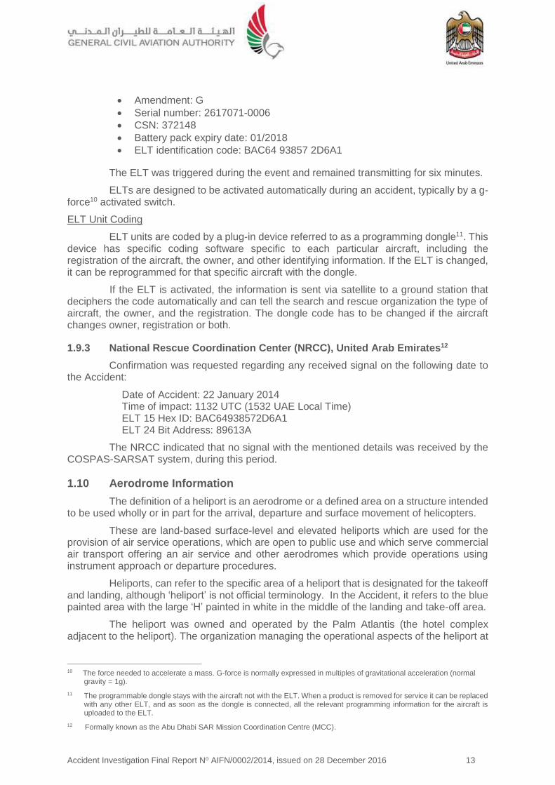
Accident Investigation Final Report No AIFN/0002/2014, issued on 28 December 2016 13
Amendment: G
Serial number: 2617071-0006
CSN: 372148
Battery pack expiry date: 01/2018
ELT identification code: BAC64 93857 2D6A1
The ELT was triggered during the event and remained transmitting for six minutes.
ELTs are designed to be activated automatically during an accident, typically by a g-force10 activated switch.
ELT Unit Coding
ELT units are coded by a plug-in device referred to as a programming dongle11. This device has specific coding software specific to each particular aircraft, including the registration of the aircraft, the owner, and other identifying information. If the ELT is changed, it can be reprogrammed for that specific aircraft with the dongle.
If the ELT is activated, the information is sent via satellite to a ground station that deciphers the code automatically and can tell the search and rescue organization the type of aircraft, the owner, and the registration. The dongle code has to be changed if the aircraft changes owner, registration or both.
1.9.3 National Rescue Coordination Center (NRCC), United Arab Emirates12
Confirmation was requested regarding any received signal on the following date to the Accident:
Date of Accident: 22 January 2014 Time of impact: 1132 UTC (1532 UAE Local Time) ELT 15 Hex ID: BAC64938572D6A1 ELT 24 Bit Address: 89613A
The NRCC indicated that no signal with the mentioned details was received by the COSPAS-SARSAT system, during this period.
1.10 Aerodrome Information
The definition of a heliport is an aerodrome or a defined area on a structure intended to be used wholly or in part for the arrival, departure and surface movement of helicopters.
These are land-based surface-level and elevated heliports which are used for the provision of air service operations, which are open to public use and which serve commercial air transport offering an air service and other aerodromes which provide operations using instrument approach or departure procedures.
Heliports, can refer to the specific area of a heliport that is designated for the takeoff and landing, although ‘heliport’ is not official terminology. In the Accident, it refers to the blue painted area with the large ‘H’ painted in white in the middle of the landing and take-off area.
The heliport was owned and operated by the Palm Atlantis (the hotel complex adjacent to the heliport). The organization managing the operational aspects of the heliport at
10 The force needed to accelerate a mass. G-force is normally expressed in multiples of gravitational acceleration (normal
gravity = 1g).
11 The programmable dongle stays with the aircraft not with the ELT. When a product is removed for service it can be replaced with any other ELT, and as soon as the dongle is connected, all the relevant programming information for the aircraft is uploaded to the ELT.
12 Formally known as the Abu Dhabi SAR Mission Coordination Centre (MCC).

Accident Investigation Final Report No AIFN/0002/2014, issued on 28 December 2016 14
the time of the Accident was Alpha Tours. At the time of the Accident, Helidubai was the contracted air service provider to Alpha Tours.
The heliport (the operational landing and take-off area) is the area within the blue demarcation zone in the images below.
The heliport’s designation was ZATL/Coordinates lat/long: 25 07.66 N/055 86.62 E.
Figure 14. Heliport at Palm Atlantis (ZATL)
1.11 Flight Recorders
For the category of EC130-B4 aircraft, light aircraft type, there was no Civil Aviation Regulations requirement for either a flight data recorder (FDR) or cockpit voice recorder (CVR) to be installed.
1.12 Wreckage and Impact Information
1.12.1 Debris mapping
The Accident location coordinates were: LAT 25° 07.66N, LONG 55° 06.82E.
Below is the view from the center of the heliport looking south, down the extended heliport centerline towards the lower end of the heliport.
Figure 1510. (Left) heliport contact witness marks. (Right) view south, down the heliport
centerline from the initial impact site

Accident Investigation Final Report No AIFN/0002/2014, issued on 28 December 2016 15
The Accident sequence occurred in two phases.
Phase one:
The first phase was the hard landing where the right cockpit door and the lower Fenestron shroud assembly separated from the structure. This occurred within the 30 seconds between takeoff and the uncontrolled descent onto the heliport.
Simultaneously, the rotor blades contacted the heliport and the surrounding terrain, damaging the rotors.
Phase two:
This phase began after the heliport impact when the Aircraft began to spin counter clockwise, the tail assembly and the rotor blades contacted elevated terrain to the east of the heliport landing area.
The Fenestron fan and tail rotor gear box assembly separated when they contact the raised ground at the side of the heliport.
The rotor or tail boom collided with firefighting equipment located at the edge of the heliport.
The Aircraft then continued to rotate around the vertical axis down the heliport, colliding with the raised ground and the tree line to the east and the car park curbing.
The various components and assemblies were scattered across and down the heliport.
The fuel tank decanting sump water drain valve, located at the lowest drain point on the fuel tank, was sheared off when the skids collapsed. Fuel was then able to gravity feed from the drain directly below the Aircraft during the ground rotation, which was approximately five minutes in duration.
1.12.2 Damage to firefighting equipment and adjacent structure
In particular, the firefighting equipment was substantially damage, in addition to a row of trees, the curbing along the edge of the heliport, and at the end of the heliport runoff area.
Figure 17. Debris pattern and component locations
Figure 16. Aircraft immediately following heliport impact

Accident Investigation Final Report No AIFN/0002/2014, issued on 28 December 2016 16
1.13 Medical and Pathological Information
The crew sustained serious injuries resulting from the Aircraft impact.
1.13.1 Crew
Both the Pilot and the HLO were transported from the heliport to a hospital due to the serious injuries they sustained.
1.13.2 Alcohol and drugs testing
Alcohol and drug testing was conducted after the event. This was completed following the Pilot’s hospitalization with negative results.
1.14 Fire
There was no evidence of a fire in-flight, or following the impact with the heliport. There was significant fuel loss as a result of damage to the fuel tank water drain which allowed fuel to drain from the fuel tank.
1.15 Survival Aspects
1.15.1 The onboard ELT
The ELT activated and transmitted a signal. However, the signal was not received by the NRCC.
The unit was removed from the Aircraft and sent for further testing to establish the fault path and the test concluded that the ELT was functioning for the duration of the Accident sequence from the time of the impact with the heliport, until the engine was shut down and the battery was turned off. This is consistent with the normal operation of an ELT.
The signal was not received by the COSPAS-SARSAT satellite Network.
1.15.2 Dynamic load transfer
The rapid descent and impact with the heliport imposed high loads onto the airframe and dynamic components resulting in several structural failures and rotor contact with the surrounding terrain.
With inelastic collisions momentum is conserved as the total momentum of both objects before and after the collision is the same.
However, kinetic energy is not conserved. Some of the kinetic energy is absorbed by the structural deformation, but the human occupants (the crew and passengers) also absorbs this energy. During a high energy impact everything moves towards the point of impact, including the occupants and the rate of change of the available energy is a major determining factor for injuries.
The seat design has a function where the energy is absorbed by the seat deforming under load, this is indicated by cracking or plastic deformation of the seat fuse restraints incorporated into the seat frame.
The kinetic energy transfer caused the seat fuse restraints to yield, as they are
Figure 11. Pilots seat deformation/structural
failure

Accident Investigation Final Report No AIFN/0002/2014, issued on 28 December 2016 17
designed to do, which lowered the Pilot’s seat position while absorbing the high deceleration loads.
Material deformation and tensile failures of the seat frames resulted from the kinetic energy transfer.
1.15.3 EASA certification: Emergency landing conditions
The Accident damaged to the available habitable occupied space was consistent with the certification requirements contained in EASA CS-27/CS, 27.561 Emergency Landing Conditions:
(a) The rotorcraft, although it may be damaged in emergency landing conditions on land or water, must be designed as prescribed in this paragraph to protect the occupants under those conditions.
(b) The structure must be designed to give each occupant every reasonable chance of escaping serious injury in a crash landing.
1.15.4 Crew and passenger seating certification
(a) The deformation observed on the damping system of the high-energy absorption seats was consistent with a high-energy vertical impact.
(b) Both occupied seats (Pilot and HLO) damping systems were triggered to their maximum range. This occurred when the seats encountered the high vertical deceleration.
The seat device was designed for downward load in accordance with EASA certification requirement for Emergency Landing Conditions, CS 27.561, paragraph (b)(3)(iv):
“CS 27.561 General
(b) The structure must be designed to give each occupant every reasonable chance of escaping serious injury in a crash landing when:
(3) Each occupant and each item of mass inside the cabin that could injure an occupant is restrained when subjected to the following ultimate inertial load factors relative to the surrounding structure:
(iv) Downward – 20 g, after the intended displacement of the seat device.”
Figure 19. Seat fuse and structural deformation

Accident Investigation Final Report No AIFN/0002/2014, issued on 28 December 2016 18
1.16 Tests and Research
1.16.1 Test flight – tail rotor control effectiveness/Fenestron audio recording
A flight test was conducted to evaluate the normal tail rotor control effectiveness with both left and right turns at approximately two meters, in ground effect (IGE), and at approximately 10 meters where ground effect was less factor.
A video/acoustic recording was also made for use as a control for later analysis of a video of the Accident for cross comparison of the Fenestron fan audio.
Turn T1, approximately 6.5 feet above ground level
Turn T2, approximately 30 feet above ground level
1.16.2 Acoustic analysis – accident video
The Accident flight audio recordings, derived from the visual recordings, were processed through sound spectrum analysis software to identify the characteristic audio signatures for the three principle sound emissions:
(a) Engine compressor
(b) Rotor rpm
(c) Fenestron blades rotation frequency.
Based on the cross comparison with the control recordings from the test flight, a comparative audio analysis was performed to verify the following:
(a) Engine function
Figure 20. Tail rotor turn rate/audio recording test

Accident Investigation Final Report No AIFN/0002/2014, issued on 28 December 2016 19
(b) Rotor speed (revolution per minute ‘rpm’)
(c) Fenestron rotation at a constant frequency
This is further detailed in Section 2 of this Report Analysis. In addition, the full audio analysis report is in the appendices of this report.
Figure 12. Acoustic analysis (Section 2 Analysis)
1.16.3 Vehicle and engine multifunction display (VEMD)
The onboard VEMD13 was functioning at the time of the Accident and all indications, cautions, and warnings were normal.
The VEMD was activated after the Accident to access the complete onboard recorded information which revealed that the system was functioning and the complete information and diagnostics display was captured.
1.16.4 Airbus Helicopters investigation report EAI N° 09/2014 MM
The manufacturer’s on-site wreckage examination report is available in the appendices.
1.16.5 Shoulder harness inertia reel function check
The shoulder harness was inspected following the Accident and verified to be in a serviceable condition, with all attachment points accounted for and no deformed or fractured due to the impact.
The shoulder harness reels were examined and subjected to a rapid acceleration test. The fit, form, and function of the locking reel was verified and the harness assembly was verified as functional and in a working condition.
13 Refer to the appendices, report reference: Rap_Sit 2014/013-1.

Accident Investigation Final Report No AIFN/0002/2014, issued on 28 December 2016 20
1.16.6 ELT function and verification testing
The ELT was tested at the manufacturer’s test facility and was verified to be in good working condition and operational at the time of the Accident.
Test report summary:
Frequencies tested: 406, 121.5 and 243 MHz: All Functioning
Limits of the main characteristics:
− 406.025 MHz ±2 kHz / 37dBm ± 2dBm − 121.5 MHz ±6 kHz / 20dBm to 26dBm − 243.0 MHz ±12 kHz / 20dBm to 26dBm − Modulation: 85% to 100%
Test results: − 406.0249 MHz / 36.6 dBm
− 121.4992 MHz / 22.0 dBm
− 243.012 MHz / 22.8 dBm
− Modulation: 97%
Conclusion:
All frequencies were transmitting and the power supply was functional (The test report is available in the appendices).
1.17 Organizational and Management Information
Helidubai is a helicopter company authorized to perform air transport operations as defined in its operations specification, in accordance with its operations manual and the UAE Civil Aviation Regulations.
Helidubai is an independent commercial operation residing within the overall organizational structure of the Dubai Air Wing. Helidubai structure organization at the time of the Accident is as illustrated in figure 22.
The number of pilots employed at the time of the Accident was 10. The types of aircraft operated were as shown in figure 23.
Figure 22. Helidubai structure organization

Accident Investigation Final Report No AIFN/0002/2014, issued on 28 December 2016 21
1.17.1 The Operator’s safety management system (SMS)
The Operator’s SMS manual was accepted by the GCAA and was effective as of 1 May 2013.
The Chief Executive Officer (CEO) was responsible for the implementation and maintenance of the SMS.
The Safety Manager, or post holder (PH) SMS, reports directly to the CEO regarding safety initiatives, monitoring, implementation and risk identification.
The PH Flight Operations was responsible for the following:
Safe execution of all flights
Implementation of controls to aid in the reduction of risk
The inclusion of the Operator’s safety policy into all flight operations operating procedures
Ensuring all flight operations staff receive training in safety. 1.17.2 Operator operational/training/safety management
The Operator’s pilots, who were not EC130-B4 type-rated, received training in South Africa at ESAL which was a GCAA-approved training organization (ATO).
The Operator also operated AS350-B3 type which could be considered as almost the same type of the Accident Aircraft. However, the Operator took the approach that both EC130-B4 and AS350-B3 were two separate types, and therefore the Operator provided yearly distinct full operator proficiency checks (OPC) on each type, every year, with six months in between the two types.
For pilots operating more than one type or variant, the OPC requirements may be satisfied by a six-month check on any one type, or variant operated. However, proficiency checks on each type or variant operated should be completed every 12 months in accordance with CAR-OPS 3.965(b).
OPC is a standard line proficiency procedures designed as an assessment of pilot skills and knowledge in a particular operational area. The Operator pilots were required to undertake proficiency checks to ensure they continue to be competent in conducting particular kinds of operations.
The Pilot received all required flight trainings and checks in accordance with CAR-OPS 3.
The Operator had no flight data management (FDM) system to monitor trends and develop mitigation processes.
Type Registration VFR IFR
AS350-B3 A6-AWR Yes No
AS350-B3 A6-WSL Yes No
AS350-B3 A6-ZBL Yes No
EC130-B4 A6-KHW Yes No
EC130-B4 A6-DYR Yes No
A109 E A6-JMR Yes Yes
A109 E A6-DBY Yes Yes
Figure 23. The Operator’s fleet size
Accident Investigation Final Report No AIFN/0002/2014, issued on 28 December 2016 22
1.17.3 Emergency response plan (ERP)
The Operator’s ERP at the time of the Accident was in accordance with the requirements of the GCAA. Following the Accident, the ERP was implemented in coordination with the Dubai Air Wing.
Under a support agreement, Emirates Airline Family Assistance and Critical Incident Stress Management (CISM) teams deployed to the site to support the Alpha Tours and Helidubai staff affected by the Accident.
1.17.4 Safety management system (SMS) Heliports
Alpha Tours, the operator of the heliport, was not required to have an SMS as the heliport operational safety was covered by the SMS of the Aircraft Operator.
1.18 Additional Information
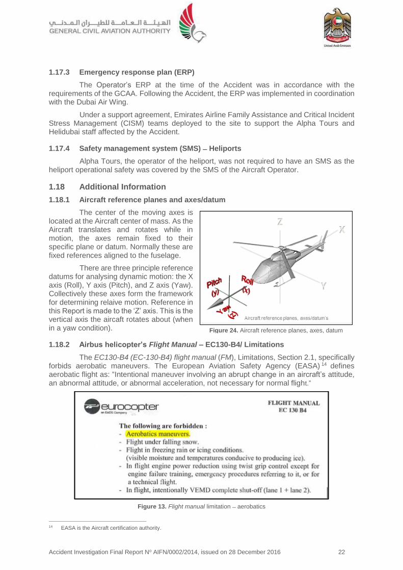
1.18.1 Aircraft reference planes and axes/datum
The center of the moving axes is located at the Aircraft center of mass. As the Aircraft translates and rotates while in motion, the axes remain fixed to their specific plane or datum. Normally these are fixed references aligned to the fuselage.
There are three principle reference datums for analysing dynamic motion: the X axis (Roll), Y axis (Pitch), and Z axis (Yaw). Collectively these axes form the framework for determining relaive motion. Reference in this Report is made to the ‘Z’ axis. This is the vertical axis the aircaft rotates about (when in a yaw condition).
1.18.2 Airbus helicopter’s Flight Manual – EC130-B4/ Limitations
The EC130-B4 (EC-130-B4) flight manual (FM), Limitations, Section 2.1, specifically forbids aerobatic maneuvers. The European Aviation Safety Agency (EASA) 14 defines aerobatic flight as: “Intentional maneuver involving an abrupt change in an aircraft’s attitude, an abnormal attitude, or abnormal acceleration, not necessary for normal flight.”
Figure 13. Flight manual limitation aerobatics
14 EASA is the Aircraft certification authority.
Figure 24. Aircraft reference planes, axes, datum
Accident Investigation Final Report No AIFN/0002/2014, issued on 28 December 2016 23
Airbus Helicopters have published several safety advisories concerning low speed
operations with particular reference to the yaw/pedal turn rate.
1.18.3 Eurocopter Letter Service No. 1673-67-04/ SUBJECT Reminder concerning the YAW axis control for all helicopters in some flight conditions
In 2005, and in response to in-service analysis of the causes of several helicopter accidents and serious incidents, Eurocopter issued service letter (SL) 1673-67-04 regarding YAW axis control in some flight situations.
The relevant text was:
"In the various cases which resulted in the loss of yaw axis control, the action applied to the RH yaw pedal was not enough (amplitude/duration) to stop rotation as quickly as the pilot wished.
As the aircraft continues its rotation, the pilot generally suspects a (total or partial) tail rotor failure and decides either to climb to gain speed or to get closer to the ground.
In the first case, increasing the collective pitch results in increasing the main rotor torque and consequently further speeds up leftward rotation. This results in the loss of aircraft control.
In the second case, sharp decrease in collective pitch can make the aircraft tilt to the side whilst rotating and cause it to touch the ground."
1.18.4 Helicopter blade coning angle
The helicopter rotor systems depend primarily on rotation to produce relative wind which develops the aerodynamic force required for flight. Due to this rotation and weight, the rotor system is subject to forces and moments peculiar to all rotating masses. One of the forces produced is centrifugal force.
When a high lift input is commanded this will cause the rotor blade disk area cone15 as the relative lift on the driven area of the rotor disk increases the path of the blade tips will move up, forming the rotor disk into a cone shape.
15 Coning: the upward angular displacement of the rotor blades under high lift. The Coning Angle is the angle between the
rotor blades and the plane normal to the axis of the hub.

Accident Investigation Final Report No AIFN/0002/2014, issued on 28 December 2016 24
Figure 14. Rotor blade coning angle blade force resolution
Figure 15. Longitudinal tilt coning angle
If the collective is pulled to increase the pitch/angle of attack of the blade, the resulting forces on the rotor blades cause the blades to cone upwards.
1.18.5 Vehicle and engine multifunction display flight report page
The purpose of the flight report page is to provide the crew with a synthetic report of the last flight performed. The end of flight report automatically replaces the "VEHICLE" page when the VEMD detects the engine shutdown and NR below 70 rpm state.
1. Flight number, which is incremented automatically
2. Flight time (from Ng>60% after start to Ng<50% at engine shutdown)
3. Generator cycles / Total cycles
4. Free turbine cycles / Total cycles
5. Message area (in yellow) if a discrepancy is detected during the flight.
If a message appears, the flight report page refers to the MAINTENANCE mode in the systems description manual.
VEMD Report for the Accident flight was as shown in figure 28.

Accident Investigation Final Report No AIFN/0002/2014, issued on 28 December 2016 25
Figure 28. VEMD screen capture
1.18.6 Hover and low airspeed stability, control, and flying qualities
This Investigation has focused on various aspects of the Aircraft control, both the mechanical systems, the low speed aerodynamics, and the human factors elements regarding the human/machine interface for the helicopter handling during the take-off phase.
This section covers the longitudinal and lateral-directional characteristics in the low speed regime, from hover to about 35 kt in order to establish the characteristics between a mechanical systems failure and pilot induced error.
The focus is on the in-ground effect (IGE) and out-of-ground effect (OGE) characteristics for hover and vertical maneuvering. Take-off and landing characteristics are included. Helicopters behave differently if in ground effect, which is a cushion of air under the helicopter as opposed to out of ground effect where the cushion of air is no longer a factor.
As coupled, the longitudinal and lateral-directional stability, control, and flying qualities aggregate the interchanged effects between the pitch, roll, and yaw. In this Accident, the primary control characteristic examined was the yaw control.
Figure 29. Helicopter control of yaw diagram

Accident Investigation Final Report No AIFN/0002/2014, issued on 28 December 2016 26
1.18.7 Rotary wing stability and control
The normal flight axes are dependent on attitude, rate (of change), acceleration, and/or control coupling.
Unusual attitude (UA) recovery: For this Investigation, the UA refers to the inflight pitch, roll, and yaw attitudes and/or rates resulting from an intentional control input commanding the aircraft to deviate from its trimmed (or balanced) flight condition.
Applicable recovery procedures depend on the aircraft being flown and the severity of the maneuver being executed.
At all times, the pilot must remain in the loop actively flying the aircraft and analyzing the aircraft response in order to maintain situational awareness and effective control of the aircraft within the certified limitations as specified by the manufacturer.
Recommended pilot recovery techniques from UAs for yaw are:
Directional control to fix the attitude of the helicopter about the z-axis by the application of right pedal.
As the rate of rotation decreases to below approximately 60 degrees per second, normal yaw directional control can be achieved and steady state directional control established.
The directional control mechanism is the Fenestron tail rotor. Lateral control is provided through control of both forces and moments through the movement of the rotor disk by the pilot’s manipulation of the cyclic control.
The tail rotor thrust is the only contribution to this derivative assuming no control coupling and neglecting any interference effects.
1.18.8 Yaw rate limitations for the EC130-B4
There was no requirement for a placarded yaw rate limitation or yaw rate limitation in the EC130-B4 flight manual.
However, the AS350-B3 helicopter Flight Manual, FM/AS 350-B3/FM 2-8 (which the Operator was operating) stated: "In hover, avoid rotation faster than 6 seconds for one full rotation.”
Verification from the manufacturer concerning the yaw limitation on the AS350-B3 and not the EC-130-B4 aircraft was the following:
"The limitation of a rotation faster that 6 seconds for one full turn introduced in the AS350-B3 Flight Manual is associated to the design of the Tail Rotor Head on the AS350-B3 variants.
Airbus Helicopters has experienced in the
Figure 30. Flight manual/AS350-B3 Hover rotation limitation

Accident Investigation Final Report No AIFN/0002/2014, issued on 28 December 2016 27
past some mechanical interferences between the Tail Rotor Blade (Chin weight) and the Tail Rotor Pitch control plate.
The analysis of these events has shown that in all the cases such interferences were the result of a significant Tail Rotor Pitch Control application to stop a high rate of rotation speed (such phenomenon can result in a significant tail rotor blade flapping depending of the rate of tail rotor pitch application and external condition).
The limit of 6 seconds for a full turn has been introduced to avoid this possible phenomenon/interference.
On the EC130-B4 the Tail Rotor Head design is different, such interference is not possible and so this limitation (is) not necessary."
The yaw rate limitation was due to the design of the AS350 aircraft tail rotor system and not related to the handling or control of the aircraft at high or excessive rates of rotation.
1.18.9 Anecdotal evidence from witness statements
Witness statements described the departure technique for the final positioning as a takeoff high turn rate maneuvers with a rapid changes of height. The Aircraft would then depart along the coast. One witness described this final flight departure was as being “Like an airshow.”
1.18.10 Civil Aviation Regulations (CAR), Part III, Chapter 2
Chapter 2 of CAR Part III prescribes regulations governing the operation of civil aircraft within the United Arab Emirates.
It is the responsibility of the authorized crew and the organizations post holders for operations and safety to manage the requirement to adhere to the Civil Aviation Regulations as described in the Operator’s air operator certificate (AOC). The related paragraphs of CAR Part III, Chapter 2, are as following:
“2.2.1 NEGLIGENT OR RECKLESS OPERATIONS
No person shall operate an aircraft in a careless or reckless manner so as to endanger the life or property of another. Careless or reckless operations may result in enforcement or other legal action against the person committing the act.
2.8.1 AEROBATIC FLIGHT
Unless specifically authorized by the GCAA no person shall operate an aircraft in aerobatic flight. Once authorized, no person shall operate an aircraft in aerobatic flight:
(a) over any congested area of a city, town, or settlement;
(b) over an open air assembly of persons;
(c) within a control area (unless authorized by ATC), control zone, or airway;
(d) below an altitude of 1500 feet above the surface; or
(e) when the visibility is less than 8 km.”
1.18.11 Requirements for in-flight data recording
In the absence of in-flight recording of the aircraft condition and operation, it can be very difficult to reconstruct the sequence of events that led to an accident or a serious incident.
Accident Investigation Final Report No AIFN/0002/2014, issued on 28 December 2016 28
Analyzing the sequence of events is necessary to develop safety recommendations and prevent future occurrences. Many investigations of aircraft accidents and serious incidents are hindered by the absence of accurate data with the circumstantial data used to reconstruct basic flight profiles.
The analysis of other types of evidence (witness statements, accident site examination, ATM recordings, etc.) is usually time-consuming and does not provide such complete and accurate data as the dedicated in-flight recording does.
Annex 6, Part III, prescribes that future light turbine-engined helicopters with a maximum certified take-off mass MCTOM of over 2,250 kg and operated for commercial air transport be equipped with a means to record flight data. Annex 6, Parts II and III, recommend that future light turbine-engine airplanes and helicopters operated for general aviation be equipped with a means to record flight data and, under certain conditions, a means to record cockpit audio.
1.19 Useful or Effective Investigation Techniques
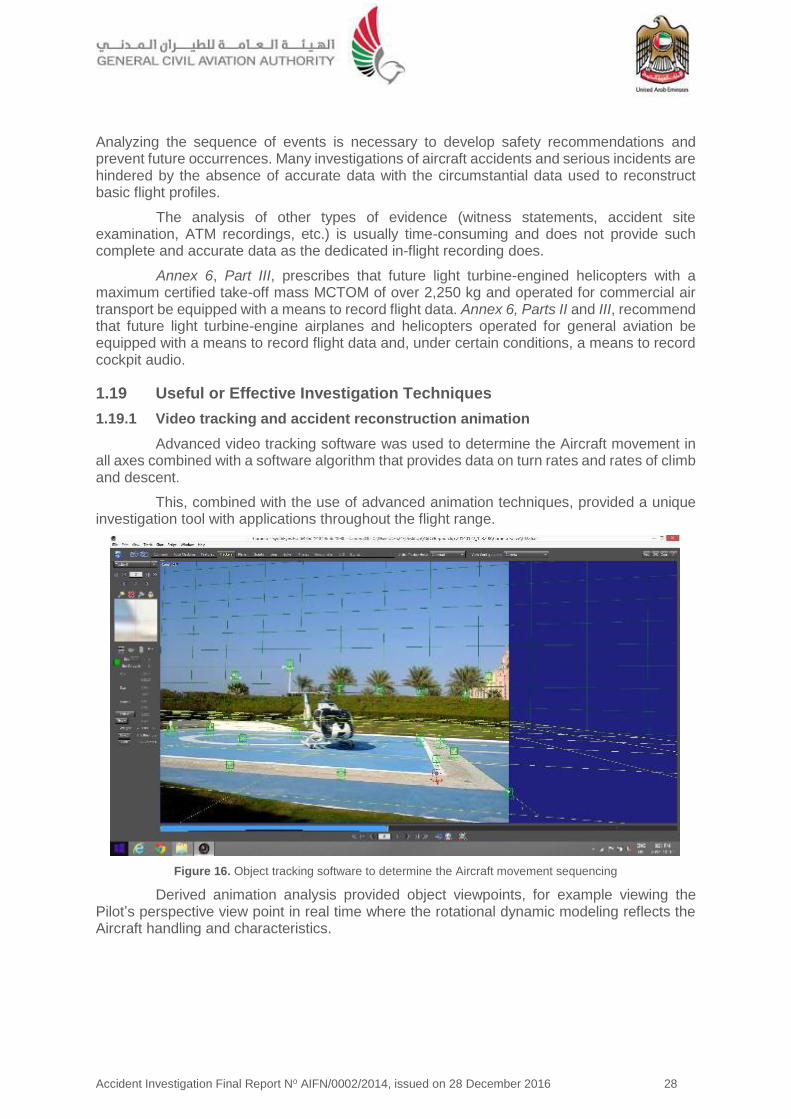
1.19.1 Video tracking and accident reconstruction animation
Advanced video tracking software was used to determine the Aircraft movement in all axes combined with a software algorithm that provides data on turn rates and rates of climb and descent.
This, combined with the use of advanced animation techniques, provided a unique investigation tool with applications throughout the flight range.
Figure 16. Object tracking software to determine the Aircraft movement sequencing
Derived animation analysis provided object viewpoints, for example viewing the Pilot’s perspective view point in real time where the rotational dynamic modeling reflects the Aircraft handling and characteristics.

Accident Investigation Final Report No AIFN/0002/2014, issued on 28 December 2016 29
Figure 32. Animation of Pilot’s perspective
1.19.2 Sound spectrum analysis (SSA)
A helicopter of this type has three distinctive principle acoustic signatures:
1. Engine
2. Main rotor
3. Tail rotor/Fenestron
SSA of these principle acoustic signatures of the helicopter involved in an accident can be compared with a baseline audio recording of a helicopter in normal operation.
This technique can analyze the audio spectrum of the accident, identifying the key audio characteristics of the dynamic components and their operating frequencies. Variations in the consistency of the rotor sped, engine pitch, and the Fenestron rotation based on this standard acoustic model can be used to support conclusions regarding the functioning of these key components, or systems, up to and at the time of the accident.
As the onboard recorded information was limited, a baseline recording was made, this was then compared to the Accident recordings to establish if differences, if they existed, identified any component failures. In particular, the functioning of the Fenestron was analyzed in comparison to the flight test recording for any indication of audio changes indicating a failure.
1.19.3 Human factors analysis and classification system (HFACS)
The HFACS is an empirically derived system-safety model that effectively bridges the gap between human error theory and the practice of applied human error analysis.
A proven safety management tool, the HFACS facilitates the reliable identification, classification, and analysis of human error in complex, high-risk systems such as aviation to systematically identify active and latent failures within an organization that have resulted in an accident.
By using the HFACS framework for accident investigation, investigators are able to identify the breakdowns within the entire system that allowed an accident to occur.
During an investigation analyzing the complex interaction between the human and machine interface is an integral part of the investigation process. The aviation system is considered as a whole, so the investigator will look at the crew, the crew and operations decision-making, engineering support, aircraft design and flight operations and/or training, air traffic control (ATC) contribution, along with various other factors which all interact with any given accident scenario.
The HFACS can also be used proactively by analyzing historical events to identify reoccurring trends in human performance and system deficiencies.

Accident Investigation Final Report No AIFN/0002/2014, issued on 28 December 2016 30
Both of these methods will allow investigators to issue safety recommendations that identify weak areas and encourage organizations to implement targeted, data-driven interventions that will ultimately reduce accident and injury rates.
The HFACS provides a structure to review and analyze the accident and supporting safety data during an investigation. This provides the investigator with a methodology to look for systemic contributing factors that may have causal factors associated with the occurrence.
By breaking down the human contribution to an accident event sequence, it enables the investigators to identify the underlying factors that are associated with the events leading up to the accident.
The HFACS framework may also be useful as a tool for guiding future accident investigations in the field and for developing better accident databases, both of which would improve the overall quality and accessibility of human factors accident data.
Common trends within an organization can be derived from comparisons of psychological origins of the initiating events, or from the latent conditions that allowed these acts within the organization. Identifying those common trends supports the identification and prioritization of where to focus the intervention within an organization.
By using the HFACS, an investigator can identify where hazards have arisen historically and implement procedures to prevent these hazards which will result in improved human performance and decreased accident and injury rates.
The goal of the HFACS is not to attribute blame; it is to understand the underlying causal factors that lead to an accident.
The HFACS framework describes human error at each of four levels of failure:
(a) Unsafe acts of operators (example aircrew)
(b) Preconditions for unsafe acts
(c) Unsafe supervision
(d) Organizational influences.
The unsafe acts level is divided into two categories - errors and violations. Errors are unintentional behaviors, while violations are a willful disregard of the rules and regulations.
Errors
Skill-based errors. Errors which occur in the operator’s execution of a routine, highly practiced task relating to procedure, training or proficiency and result in an unsafe situation (example: fail to prioritize attention, checklist error, negative habit).
Decision errors. Errors which occur when the behaviors or actions of the operators proceed as intended yet the chosen plan proves inadequate to achieve the desired end-state and results in an unsafe situation (example: exceeded ability, rule-based error, or inappropriate procedure).
Perceptual errors. Errors which occur when an operator's sensory input is degraded and a decision is made based upon faulty information.
Violations
Routine Violations. Violations which are a habitual action on the part of the operator and are tolerated by the governing authority.
Exceptional Violations. Violations which are an isolated departure from authority, neither typical of the individual nor condoned by management.

Accident Investigation Final Report No AIFN/0002/2014, issued on 28 December 2016 31
2 Analysis 2.1. General
To simplify the Accident, the sequence is divided into two phases.
Phase One. Is the takeoff and impact on the heliport.
Phase Two. Is the ground rotation along the heliport.
In order to provide the reader with continuity during the event sequence explanation, the information is presented as a combination of factual information from Section 1 of this report and with additional analytical explanation contained in this Section 2 of the Report.
2.2 Accident Sequence – Phase One
This phase describes the lift-off, the entry into the yaw condition and the subsequent unstable ascent and descent.
The Aircraft lifted into the hover and immediately began a counter clockwise yaw.
This yaw direction, to the left from the Pilot’s perspective, was the natural yaw condition for the Aircraft due to the torque loads induced by the main rotor on the airframe.
The Aircraft started to rotate about the z-axis, the rotation rate accelerated as a function of the time while airborne.
To simplifiy the take-off sequence, there are a series of photos taken at one-second intervals with the information displayed on a simple graphic key as below.
Figure 33. Key to the video/animation sequence
The following sequence is a combination of the video footage taken by a handheld
device synchronised with the animation cockpit view.
The video snapshots are at one-second intervals.

Accident Investigation Final Report No AIFN/0002/2014, issued on 28 December 2016 32
(A) The Aircraft on the heliport,engine running prior to takeoff
(B) The start of the takeoff sequence. The Aircraft picked up into a low hover and immediately began to turn to the left
(C) The turn continued; the Aircraft gained height
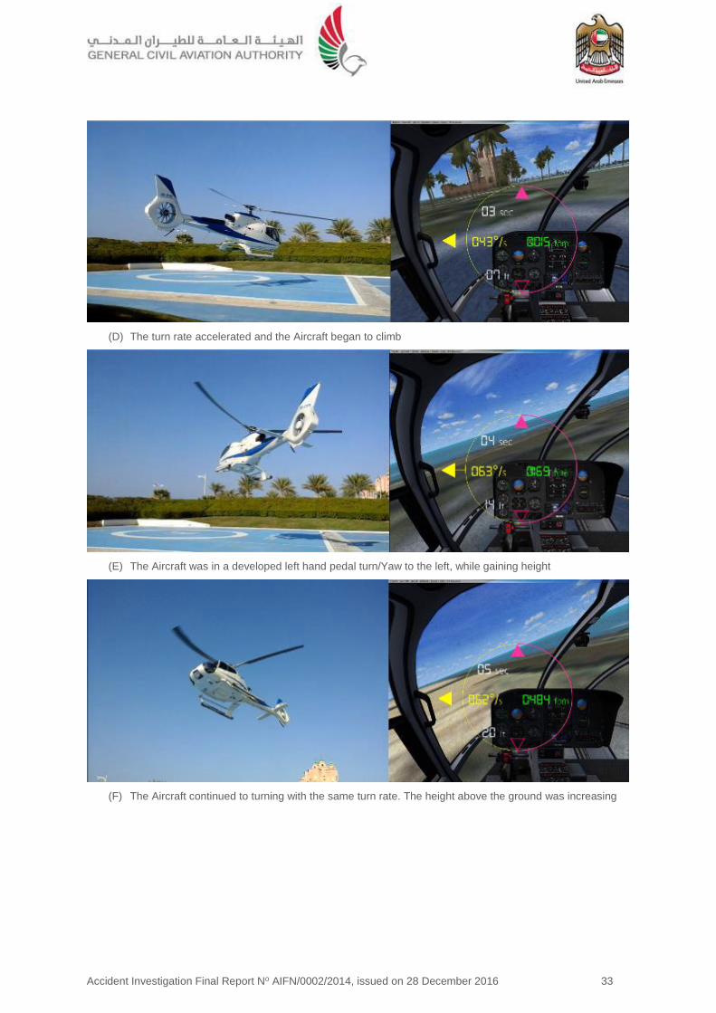
Accident Investigation Final Report No AIFN/0002/2014, issued on 28 December 2016 33
(D) The turn rate accelerated and the Aircraft began to climb
(E) The Aircraft was in a developed left hand pedal turn/Yaw to the left, while gaining height
(F) The Aircraft continued to turning with the same turn rate. The height above the ground was increasing

Accident Investigation Final Report No AIFN/0002/2014, issued on 28 December 2016 34
(G) The turn continued with increased turn rate, the height above ground continued to increase
(H) The Aircraft has entered an accelerating, high turn and was continuing to climb
(I) The turn continued and the height above the ground was increasing

Accident Investigation Final Report No AIFN/0002/2014, issued on 28 December 2016 35
(J) The turn continues with increased turn rate and the height above the ground is increasing
(K) The Aircraft was continuing to turn at about 182° per second. The rate of descent increased significantly
(L) The dynamic condition of the Aircraft immediately prior to the heliport impact was the following:
Rate of Descent = 2423 feet per minute
Rate of Rotation = 166º per second

Accident Investigation Final Report No AIFN/0002/2014, issued on 28 December 2016 36
Figure 34. Yaw rate
Approaching the nine second mark, at 8.61 second, based on the video derived analysis, the maximum rate of rotation peaks was at 258.42° per second. At the point of impact with the heliport, the yaw rate (the rate of rotation) was 166° per second.
The maximum height above ground is at the 10 seconds mark: 72 feet (22 meters).
The derived climb profile indicating the maximum height above the heliport and the flight cycle duration.
-300
-250
-200
-150
-100
-50
0
50
0 5 10 15
Aircraft Turn Rate deg/sec
Turn Rate
Figure 35. Maximum height above the ground

Accident Investigation Final Report No AIFN/0002/2014, issued on 28 December 2016 37
The picture above is a combination of a CCTV screenshot at the point of impact with the heliport and an Accident sequence video. In the screenshot, the back ground image above, The Aircraft bounced up briefly while continuing to rotate counter clockwise.
The Aircraft impacted the heliport with a high rate of descent, followed immediately by a brief period, about two seconds, where the Aircraft was airborne from the heliport while rotating. This was the result of the airframe bouncing up from the impact point.
2.3 Event Sequence Parameters
The impact onto the heliport imposed high vertical loads into the airframe and dynamic components, resulting in several simultaneous structural failures, and the rotor to contact with the surrounding terrain.
The kinetic energy transfer resulted in the seat fuse restraints16 yielding, which lowered the Pilot’s seat position while absorbing the high deceleration loads.
The Pilot’s door opened (the left hand door) and the crewman’s right hand door separated one second following the impact.
Due to the Pilot’s seat lowering vertically as a result of the high deceleration loads, the Pilot was not fully restrained in the harness as the Aircraft began to rotate.
The Pilot sustained multiple serious injuries to the head, upper body and was non-responsive following the impact with the heliport.
16 The design of the seat requires the seat to absorb the high imposed dynamic loads of vertical deceleration to protect the
occupant, typically up to or exceeding 20g. The seat achieves this by a structural limitation that absorbs the loads resulting in progressive structural failure of the seat at predetermined points of the design.
Figure 36. Aircraft dynamic condition at point of impact
Figure 37. Combined flight parameters

Accident Investigation Final Report No AIFN/0002/2014, issued on 28 December 2016 38
The Pilot was visible in the CCTV footage partially outside of the Aircraft, restrained by the Pilot’s lap strap only, with the upper body region outside of the Aircraft as the Aircraft rapidly rotated.
2.4 Rotor Disk Coning
As described in Section 1 of this Report Factual Information, the amount of rotor disk coning depends on the main rotor speed, the Aircraft gross weight, and the g-forces experienced during the Accident maneuver.
If rotor speed is held constant, coning increases as gross weight and/or g-force increases. In the Accident image analysis, the rotor tip path and the rotor disk plane were on the same axis which indicates that no coning was evident as the collective lever was lowered and not increasing the rotor blade angle to the relative airflow. The rotor was at a low angle of attack and not generating significant lift.
2.5 Accident Sequence - Phase Two
2.5.1 Uncontrolled ground rotation
This phase of the Accident sequence involves the engine power setting and the loss of tail rotor effectiveness, resulting in uncontrolled counter clockwise high turn rate rotation on the heliport and along the length of is a snap shot of the Aircraft movement along the extended centerline of the heliport.
Following the rapid descent and impact with the heliport, the Pilot was unresponsive and the Aircraft, under power and with some pitch on the main rotor blades, rotated counter clockwise (left) along the heliport, contacting various surrounding structures until coming to a full stop approximately five minutes after the initial heliport impact.
The engine condition setting on the collective was in the Flight position. The throttle control on the collective is used only for engine startup and shutdown, for engine reduction in case of a tail-rotor failure, and during autorotation training.
Figure 39. CCTV Image of Aircraft movement on the heliport
Figure 38. Rotor tip path plane and rotor disk conning
Figure 40. Throttle position was in ‘Flight’ setting

Accident Investigation Final Report No AIFN/0002/2014, issued on 28 December 2016 39
The full authority digital engine control (FADEC) controls the engine power turbine speed (Nf) independently of the power drawn from the engine by adjusting gas generator speed (Ng), as needed.
With the throttle in the Flight indent position, the FADEC would attempt to maintain the engine performance and torque requirements to maintain the nominal rotor rpm (Nr).
2.5.2 Debris distribution and Aircraft movement
Following the initial impact with the heliport on the blue landing/departure area, the Aircraft then traveled down the heliport (from the position of the white ‘H’), rotating counter clockwise. The Aircraft traveled the entire length of the heliport before stopping at a curb (a small retention wall) at the end of the heliport, adjacent to the roadway.
The Aircraft rotated down the heliport for five minutes, with the crew incapacitated with the engines developing power and the rotors turning with collective pitch.
Figure 41 is a composite image taken from the CCTV video of the Aircraft travelling down the heliport.
From the observer’s position at the CCTV camera, the distance to the far curb was approximately 100 meters.
Photos one to four demonstrate the progression of the Aircraft down the heliport. The period from the position in photo one to photo four was approximately two minutes. The Aircraft was rotating constantly.
2.6 Shoulder Harness Inertia Reel Locking Mechanism, High Rotational rates, Rotational Inertia and Pilot Body Position During the Accident Sequence
The function of the inertia reel is to lock and restrain the occupant in a crash, yet provide the ability for normal movement without restrictions.
As the Aircraft lifted off, the yaw rate increased, reaching a maximum yaw rate of 258° per second.
In the initial stages of the left hand pedal turn, the rotational acceleration was sufficient to propel the crew torsos forward due to the high rotational yaw rate.
The shoulder harness has a locking mechanism that will lock the free play of the harness if the rate of acceleration is equal to or exceeds 1.5 g. If the acceleration is below 1.5 g, the shoulder harness is not locked allowing the body position of the crew to move forward. During the turn, the increasing rate of rotation was constant and approximately linear, up until the seven second mark.
At the eight second mark the Pilot’s body position was forward, the rate of rotation was approximately 105 degrees per second.
The assumption is that for the Pilot to be inclined forward the rotational inertia has to be sufficient to propel the upper body position forward, all of which can only occur if the acceleration in the X-axis is equal to or less than 1.5 g.
Figure 41. Composite of the CCTV photos

Accident Investigation Final Report No AIFN/0002/2014, issued on 28 December 2016 40
Figure 42. Pilot’s body position at the 8-second mark
Analysis of the Accident video clearly indicates that Pilot’s upper body was forward. The Pilot’s forward body position remained inclined (forward) for the remaining duration of the Accident sequence.
The Pilot was inclined forward at the time of impact. The function of the inertia reel design would only lock at or above 1.5g, which was not the case during the high rotation rates.
Figure 43. Pilot’s forward inclined body position
As the Aircraft contacted the heliport with a high rate of deceleration, a rate of descent of approximately 2,423 feet per minute, the Pilots upper body/torso connected with the cyclic control with sufficient force to deform the inside of the control column radius.
Figure 44. Pilot’s forward inclined body position and cyclic control deformation
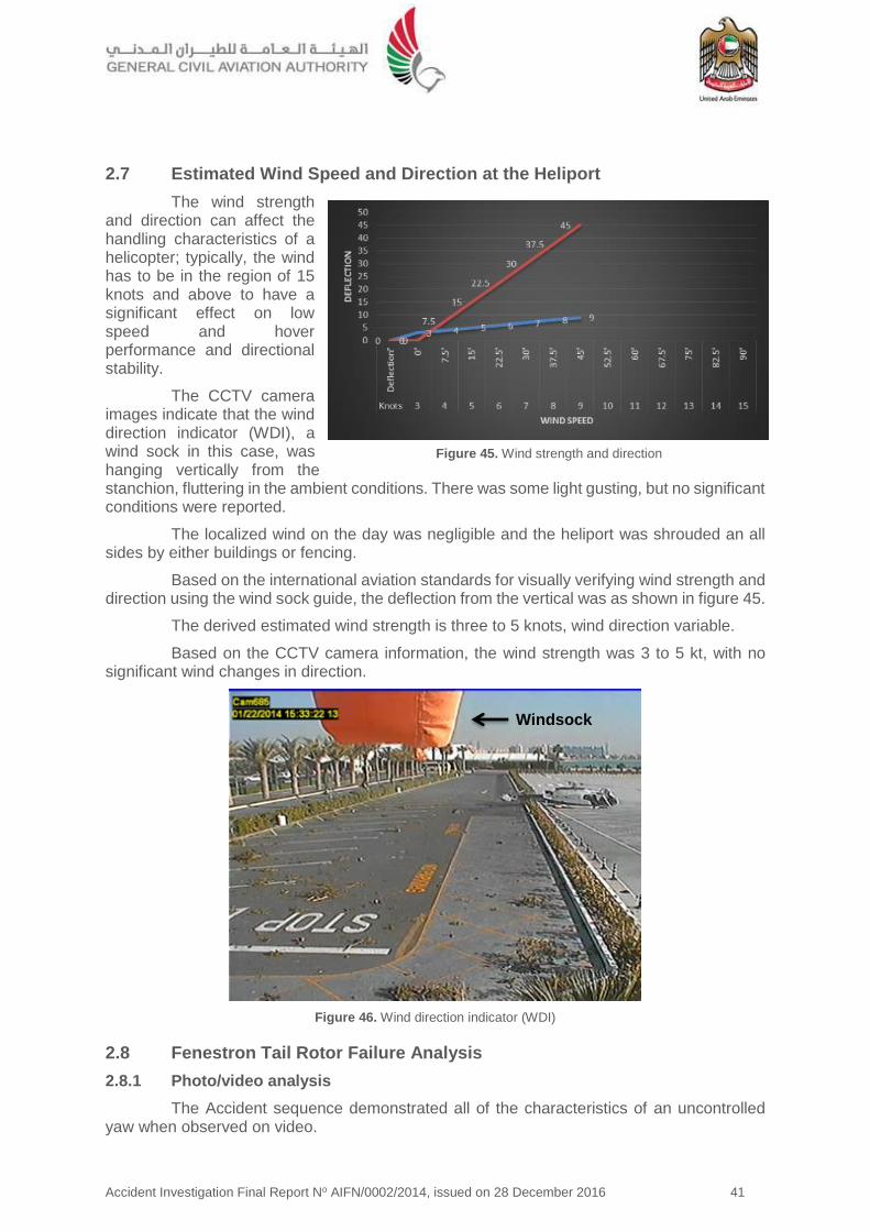
Accident Investigation Final Report No AIFN/0002/2014, issued on 28 December 2016 41
2.7 Estimated Wind Speed and Direction at the Heliport
The wind strength and direction can affect the handling characteristics of a helicopter; typically, the wind has to be in the region of 15 knots and above to have a significant effect on low speed and hover performance and directional stability.
The CCTV camera images indicate that the wind direction indicator (WDI), a wind sock in this case, was hanging vertically from the stanchion, fluttering in the ambient conditions. There was some light gusting, but no significant conditions were reported.
The localized wind on the day was negligible and the heliport was shrouded an all sides by either buildings or fencing.
Based on the international aviation standards for visually verifying wind strength and direction using the wind sock guide, the deflection from the vertical was as shown in figure 45.
The derived estimated wind strength is three to 5 knots, wind direction variable.
Based on the CCTV camera information, the wind strength was 3 to 5 kt, with no significant wind changes in direction.
Figure 46. Wind direction indicator (WDI)
2.8 Fenestron Tail Rotor Failure Analysis
2.8.1 Photo/video analysis
The Accident sequence demonstrated all of the characteristics of an uncontrolled yaw when observed on video.
Windsock
Figure 45. Wind strength and direction

Accident Investigation Final Report No AIFN/0002/2014, issued on 28 December 2016 42
Consequently, determining the potential origin for the loss of yaw effectiveness and the uncontrolled yaw was a requirement for the causal factor analysis.
Analysis of the Accident video and the sound spectrum analysis (SSA) indicated that the tail rotor assembly was intact prior to the impact and the Fenestron was rotating under power.
Recovery of the assembly, coupled with further onsite investigation, enabled a detailed structural failure analysis of the dynamic components.
This damaged component analysis was consistent with a system failure caused by the ground contact, followed by the loss of the tail rotor, which resulted in the Aircraft’s uncontrolled ground rotation.
2.8.2 CCTV image capture of the Fenestron immediately following impact
The Accident sequence was well documented. The CCTV of the heliport captured 95% of the Accident sequence. The stills image above ten seconds from the impact clearly indicates the shroud damage.
The lower edge of the Fenestron shroud was located adjacent to the heliport. Once the shroud was removed, the Fenestron static and rotating fan blades would have contacted the ground.
2.8.3 Damage to the Fenestron rotating parts and the drive shaft torque tube connection
Figure 48. Fenestron and torque tube damage
The structural failures were all recorded. A structural investigation was conducted to determine evidentially the condition of the Fenestron fan and torque tube at the time of the impact.
Deformation of the Fenestron fan and the supporting static structures was consistent with the impact.
There was high speed damage to some blades due to rotation, the majority of the damage to the unpowered Fenestron was caused by the rotation of the Aircraft and contact with the ground.
Figure 47. Fenestron shroud damage immediately
following the impact

Accident Investigation Final Report No AIFN/0002/2014, issued on 28 December 2016 43
The torque tube to Fenestron drive shaft connection depicted marks of tensile failure occurring at the fastener location (figure 48).
2.9 Acoustic/Sound Spectrum Analysis – Accident Video
The event sequence had been filmed on an iPad, a handheld tablet device. By taking the recorded video’s sound recording, cross comparing this with a control recording made by a second EC130-B4, it was possible to identify the key characteristics in the sound spectrum which relate to the rotor speed vibration, the Fenestron rotational vibration, and the engine axial compressor vibration. The Accident recording was then analysed.
A method for determining the resonant frequency of vibration of a rotating blade comprises determining the approximate resonance frequency and rotating a blade at a plurality of frequencies in a range above and below the approximate frequency.
The Fenestron rotating at a constant nominal speed (3,588 rpm) presents a harmonic spectrum made up of various frequencies which must be spaced of an approximate value of 120 Hz.
On the sound spectrum the frequency spacing can be observed. For example, at 21 seconds (the end of the flight/terminating sequence), it is possible to identify a family of frequencies related to the Fenestron (430, 550, 670, 790 Hz).
This frequency spacing, although modulated by the Doppler effect, does not visually evolve i.e. the nominal rotating speed of the Fenestron is therefore constant (including the Doppler effect variation) during the entire event sequence from takeoff until impact with the heliport, including the rapid descent phase from the 17 to 21 second marks.
Based on the acoustic evidence, the Fenestron was rotating at the required frequency during the entire event phase, and was powered for the duration.
Therefore, the Investigation concluded that this Accident was not caused by loss of tail rotor power.
2.10 Loss of Tail Rotor Effectiveness (LTE)
LTE is typically defined as ‘a critical low-speed aerodynamic flight characteristic which can result in an uncommanded or uncontrolled rapid yaw rate, which does not subside or dampen of its own accord and, if not corrected, can result in the loss of Aircraft control.
This means in practice is that the pilot could have the feeling that the pedals appear to stop working properly if the required pedal application is not anticipated and the helicopter starts turning in circles although the pilot continues to make insufficient opposite control inputs to counter the turn.
Based on the Pilot’s statements and the Aircraft behavior, a simple flight test was conducted. In conjunction with extensive detailed analysis of the various data recordings, it is concluded that this Accident was not caused by loss of tail rotor power which caused by a mechanical failure.
The wind speed and direction at the time of the Accident was low at maximum approximately 5 kt, with no significant wind changes in direction. The Aircraft was facing into wind at the point the Pilot pulled power to the hover. For a clockwise rotating main rotor, maximum tail rotor thrust is required with a crosswind component from the left.
2.10.1 Review of previous accident investigations involving LTE
Following several accident investigations involving a sudden loss of yaw control, a phenomenon known as ‘Fenestron stall’ was identified as a contributing factor.

Accident Investigation Final Report No AIFN/0002/2014, issued on 28 December 2016 44
A trial took place in 1992/93 and demonstrated that, in conditions of low natural wind, a relatively small left pedal input of 5% (of total pedal travel) from the hover position can result in a yaw rate of 150° per second being achieved in 10 seconds.
It also showed that high yaw rates to the left (165° per second) can be rapidly arrested by application of full right pedal, without any tendency for aerodynamic stall of the Fenestron.
The trial did not establish why a small pedal input can result in the rapid buildup of very high yaw rates. However, an earlier study, in 1991, by Westland Helicopters Limited had suggested that the trigger mechanism might involve a coupling of Fenestron rotor induced swirl with the circulation contained in the main rotor tip vortices, which may become aligned with the Fenestron in certain flight conditions.
The study also suggested that consideration should be given to changing the direction of rotation of the Fenestron to become top-blade-aft which would solve the interactional aerodynamic problem.
Subsequent Fenestron-equipped helicopters such as the EC130-B4 have top-blade-aft Fenestron rotation; they are not known to suffer from sudden loss of yaw control induced by this aerodynamic phenomenon.
2.11 Abnormal Attitude Recovery
2.11.1 Safety information
The majority of the helicopter safety information, from numerous manufacturers and safety organizations, places the emphasis on awareness of the prevention of an abnormal attitude condition developing.
In the event that a situation develops beyond the rotorcraft flight manual (RFM) normal flight envelope there is no guidance on the preferred recovery techniques.
Incidental data, based on exercises performed in level D full flight simulators, simulating high turn rates at low altitude and speed, using the tail rotor only to induce the rotation, indicates recovery from high rotation rates (typically ≤ 100° per second) is possible
with the full application of opposite pedal until the rotation is arrested, or is stabilized. However, control of the height above ground is problematic coordinating the collective inputs and engine demands.
The pilot has to recognize the abnormal situation has developed and apply corrective action without delay.
2.12 Vehicle and engine multifunction display (VEMD)
The battery was connected and the VEMD was activated.
A full diagnostic review of the on-board recorded faults indicated an engine over limit (EOL) detection, along with various other recorded failures or warnings.
The engine monitoring and performance data was captured as per design.
All of the read out information was consistent with the engine performance observed and indicated that the engine was functioning as Figure 49. VEMD screen capture of the
Accident
Accident Investigation Final Report No AIFN/0002/2014, issued on 28 December 2016 45
designed for the duration of the flight and Accident sequence.
2.13 Emergency Locator Transmitter (ELT) Signal
2.13.1 KANNAD 406 AF-H emergency locator transmitter
The NRCC confirmed that either no signal with the BAC Code BAC64938572D6A1 had been detected by the COSPAS-SARSAT system, or the signal was not received at the MCC during the period of the Accident.
In order to determine the root cause of the ELT signal transmission/reception at the MCC, the factors that determine the minimum performance standard meaning that each separate component of equipment (antenna, transmitter and battery) had to be tested and verified to be in a serviceable condition.
As the vertical deceleration of the heliport impact was high, the ELT should have triggered the ‘g’ (impact acceleration) switch as the ELT is g-load switch activated by a micro switch.
The ELT was sent to its manufacturer facilities for inspection through the Accredited Representative of the State of Design (BEA). The ELT examination was performed on 27 May 2014 according to the manufacturer’s test protocol and validated by the BEA. The ELT passed the tests.
An external visual inspection was performed at BEA and the following were observed:
The computer was in good condition
The power switch was on the OFF position
The ELT was manufactured in 2007 and programmed for the last time in February 2013, by Hawker Pacific Avionics, Dubai.
The ELT was programmed using the protocol 24-bit address 89613A. The Protocol 15 Hex ID stored in the ELT was different from its label and the ID stored on the COSPAS-SARSAT and Kannad databases.
39 self-testing and eight bursts were recorded. Once activated, the ELT transmitted a burst every 50 seconds. So it transmitted for 400 seconds (6 minutes 40 seconds) after the impact.
The ELT was tested and the recorded data was downloaded. The results complied with all the manufacturer’s specifications.
2.13.2 Programming dongle
A discrepancy was detected between the actual coding of the ELT (from the Aircraft dongle) and the supposed coding of the ELT as labeled on it.
The ELT has to be registered with the national authority in charge of search and rescue (SAR), with the SARSAt17 point of contact (SPOC).
In this case, the supposed coding number for the ELT BAC64 93857 2D6A1 was to be the registered code number, however, the BACDE 2584E 801A5 code was the number assigned to the ELT.
17 COSPAS-SARSAT is the international satellite system for search and rescue (SAR). When manually activated, or
automatically activated upon immersion, beacons send out a distress signal. The signals are monitored worldwide and the location of the distress is detected by non-geostationary satellites, and can be located by some combination of GPS trilateration and doppler triangulation.

Accident Investigation Final Report No AIFN/0002/2014, issued on 28 December 2016 46
The information received at SPOC was for the former registered owner of the Aircraft. This discrepancy occurred when the current Operator purchased the Aircraft from the lessor and did not reregister the ELT BAC Code as the registered owner, consequently, the ELT transmission, when detected, would register as the previous Aircraft registration, not the current registration. According to the lease/purchase agreement between the lessor and the Operator, the date to change the ownership of the Aircraft would be on 15 January 2015.
2.14 Fuel Drain Location
The location of the fuel drain, although located at the lowest position on the fuel drain path, was a fuel spill hazard for high vertical deceleration events where the skids may separate or splay outwards under load.
Ergonomically, the location was optimized for access by the servicing or operating crew. The risk was that the fuel drain, when damaged, allows the remaining fuel to gravity flow from the tank.
Recessing the drain location through a modification, or the addition of a no-return valve, would mitigate the fuel spillage risk.
2.15 Safety Management System (SMS)
2.15.1 Risk assessment
The Operator’s SMS was fully implemented and structured on accepted SMS international best practice and approved by the GCAA.
One aspect of the risk assessment that could be enhanced was the introduction of a risk analysis based on integrated flight data monitoring program to monitor safety occurrence and trends. However, since there were no flight recorder carriage requirements for the light helicopter category in commercial operation (weight between 2,250 and 3,175 kg), many operators of these light helicopters category have no obligations to install flight recorders on their aircraft. Therefore, a flight data monitoring and analysis program as part of its safety management system was not an obligation on the operators. This was also the circumstances with Helidubai, since CAR-OPS 3 did not require for this category of helicopter in commercial operation to be equipped with an in-flight data recording device.
2.16 Human Factors Analysis
The human factors analysis and classification system (HFACS), the empirically derived system safety model used by investigators in the practice of applied human error analysis for investigation was used to determine human factors causal the following evaluation for this Accident18.
The conditional parameters are in red.
HFACS Level 1: Unsafe Acts
HFACS Level 2: Preconditions for Unsafe Acts
18 Refer to Section 1 Factual Information, subsection 1.19.3 Human Factors Analysis, for a comprehensive
explanation of the methodology.
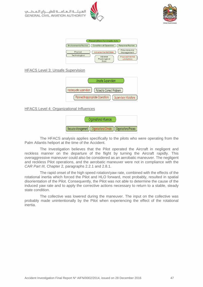
Accident Investigation Final Report No AIFN/0002/2014, issued on 28 December 2016 47
HFACS Level 3: Unsafe Supervision
HFACS Level 4: Organizational Influences
The HFACS analysis applies specifically to the pilots who were operating from the Palm Atlantis heliport at the time of the Accident.
The Investigation believes that the Pilot operated the Aircraft in negligent and reckless manner on the departure of the flight by turning the Aircraft rapidly. This overaggressive maneuver could also be considered as an aerobatic maneuver. The negligent and reckless Pilot operations, and the aerobatic maneuver were not in compliance with the CAR Part III, Chapter 2, paragraphs 2.2.1 and 2.8.1.
The rapid onset of the high speed rotation/yaw rate, combined with the effects of the rotational inertia which forced the Pilot and HLO forward, most probably, resulted in spatial disorientation of the Pilot. Consequently, the Pilot was not able to determine the cause of the induced yaw rate and to apply the corrective actions necessary to return to a stable, steady state condition.
The collective was lowered during the maneuver. The input on the collective was probably made unintentionally by the Pilot when experiencing the effect of the rotational inertia.
Accident Investigation Final Report No AIFN/0002/2014, issued on 28 December 2016 48
3 Conclusions 3.1 General
To serve the objective of this Investigation, the following subheadings are included in Section 3 of this Report:
Findings are statements of all significant conditions, events or circumstances in this Accident. The findings are significant steps in this Incident sequence but they are not always causal or indicate deficiencies.
Causes are actions, omissions, events, conditions, or a combination thereof, which led to this Accident.
Contributing factors are actions, omissions, events, conditions, or a combination thereof, which, if eliminated, avoided or absent, would have reduced the probability of the Accident occurring, or mitigated the severity of the consequences of the Accident. The identification of contributing factors does not imply the assignment of fault or the determination of administrative, civil or criminal liability.
Non-contributing safety issues are actions, omissions, events, conditions, or a combination thereof, which did not contribute to the occurrence of this Accident but are considered a source of safety risk.
From the available evidence and derived analysis, the following findings, causes and contributing factors were made with respect to this Accident.
3.2 Findings
3.2.1 The Aircraft was certified, equipped and maintained in accordance with existing Civil Aviation Regulations of the United Arab Emirates.
3.2.2 The flight crew was licensed and qualified for the flight in accordance with existing Civil Aviation Regulations.
3.2.3 The Aircraft was airworthy at the time of departure.
3.2.4 The heliport was certified in accordance with the heliport certification requirements at the time of the Accident.
3.2.5 The Pilot performed a departure technique for the final positioning which was a takeoff high turn rate maneuvers with a rapid changes of height.
3.2.6 The Pilot operated the Aircraft in negligent and reckless manner on the departure by turning the Aircraft rapidly, which was not in compliance with the CAR , Chapter 2, paragraph 2.2.1, regarding negligent and reckless pilot operations, and paragraph 2.8.1, regarding aerobatic flight.
3.2.7 The Aircraft tail boom or rotor blades struck the heliport airfield rescue and firefighting equipment positioned adjacent to the heliport.
3.2.8 There was no published final approach and takeoff (FATO) plates or procedure available to the pilots using the heliport.
3.2.9 The Pilot had resigned from the position with Helidubai and was working the required notice period at the time of the Accident.
3.2.10 Weather conditions at the time of the Accident were good, with the wind across the heliport at maximum 5 kt.

Accident Investigation Final Report No AIFN/0002/2014, issued on 28 December 2016 49
3.2.11 ELT dongle and HEX code were not coded for the current registration. The Aircraft registration and the ELT registered aircraft registration did not match, as the Aircraft had not been recorded since the change of the ownership of the Aircraft to the Operator was yet made.
3.2.12 National Rescue Coordination Center of the United Arab Emirates did not receive the supposed ELT signal (with BAC Code BAC64938572D6A1) during the time period the ELT was active and transmitting.
3.2.13 The fuel drain location where there is a structural failure of the landing skids allows the fuel drain valve to contact the terrain, which if the fuel drain is damaged, allows the fuel to flow out of the fuel tank.
3.2.14 The Accident was not caused by loss of tail rotor effectiveness or by a mechanical systems failure.
3.2.15 There was no regulatory requirement for this category of helicopter in commercial operation to be equipped with an in-flight data recording device.
3.3 Causes
The Air Accident Investigation Sector (AAIS) determines that the causes of the Accident were:
3.3.1 Intentional entry into a continuous left hand pedal turn, which rapidly increased the rotation rate of the Aircraft leading to an unstable condition developing outside of the Pilot’s ability to respond, resulting in a loss of control in-flight (LOC-I) and impact with the heliport.
3.3.2 Spatial disorientation resulting from the rapid onset of the yaw/high speed rotation combined with the effects of the rotational inertia forcing the Pilot and HLO forward.
3.3.3 The Pilot’s inability to determine the cause of the induced turn rate and apply the corrective actions necessary to return to a stable, steady state condition.
3.3.4 The collective was lowered resulting in an uncontrolled descent onto the heliport.
3.4 Contributing Factors
The Air Accident Investigation Sector determines that contributing factors to the Accident were:
3.4.1 Unforced skills based errors by the handling Pilot.
3.4.2 Poor Pilot judgment of the Aircraft handling requirements for the intended maneuver.
3.4.3 The acceleration of the inertia reel due to the rotational inertia acting on the Pilot and HLO of the Aircraft during the initial phase of the takeoff was insufficient to activate the 1.5 g locking mechanism. This subsequently allowed their upper torso to be propelled forward due to the high rotational inertia generated by the excessive yaw maneuver.
3.4.4 No requirement for a flight data monitoring system which can detect safety occurrence and trends when monitored effectively.

Accident Investigation Final Report No AIFN/0002/2014, issued on 28 December 2016 50
4 Safety Recommendations 4.1 General
The safety recommendations listed in this Report are proposed according to paragraph 6.8 of Annex 13 to the Convention on International Civil Aviation, and are based on the conclusions listed in Section 3 of this Report; the Air Accident Investigation Sector (AAIS) expects that all safety issues identified by the Investigation are addressed by the receiving States and organizations.
4.2 Safety Actions Taken
4.2.1 Safety actions taken by Helidubai
Prior to the publication of this Report, Helidubai informed the AAIS that it had taken the following safety actions:
(a) Pilot selection board Introduced.
To ensure that Helidubai employs a suitable candidate, a new pilot selection board was introduced. The board would convene and consist of senior management and post holders. Employment is only offered after an extensive selection process and to those with an instructional background.
(b) Fleet reduction
After the Accident, the Helidubai fleet was reduced and the EC130-B4 was disposed of and was not replaced.
(c) Cross-tasking
In order to prevent monotony during routine and frequent ‘sightseeing’ flights, the majority of pilots are now cross-trained in other areas such as ‘filming’ flights. (Not inserted in any source document per se, but managed by the departmental Post Holders).
(d) Closer supervision
Helidubai SMS and risk management policy recognizes pilot unmonitored behavior as a potential risk, in the absence of an FDM facility, HD aircraft movements are routinely monitored for trends associated performance exceedance that can lead to an incident or accident. (SMS Manual).
Training and the OPC, in line with CRM and the identification of systemic safety issues in HD empathize that at all time the aircraft shall be operated in accordance with the CAR-OPS 3 and the aircraft manufacturer’s limitations.
(e) Delivery of technical bulletins and service letters
The delivery of important technical bulletins and service letters was improved to ensure that all pilots received them through the QA system. (Helidubai AD/Bulletin/Amendment Control Form). Policy introduced in 2014 but now inserted into FSl No. 02/2016.
(f) Standard operating guide
Although all pilots were given a full type rating conversion onto the B4 in South Africa at a GCAA-approved ATO, an additional in-depth guide detailing the differences on Airbus Helicopters was introduced.
Accident Investigation Final Report No AIFN/0002/2014, issued on 28 December 2016 51
4.2.2 Safety Actions taken by Alpha Tours/Palm Atlantis
Prior to the publication of this Report, Alpha Tours/Palm Atlantis informed the AAIS that it had taken the following safety actions:
(a) The heliport owner (Palm Atlantis) and the tour operator (Alpha Tours) have proactively modified the heliport to comply with CAAP 7019.
(b) Including installing a security fence, lifting obstructions to the CCTV camera.
(c) Training and certifying heliport personnel.
(d) Providing safe and secure passenger transit vehicles.
(e) Stipulating helicopter operator’s contractual obligations to provide the required SMS justifications and FATO plates for operating into and out of the heliport.
4.2.3 Safety Actions taken by the European Aviation Safety Agency (EASA)
Eight safety recommendations were already addressed previously to EASA by other accident investigation authorities, recommending the introduction of in-flight recording for light aircraft. Consequently, in-flight recording for light aircraft was considered by EASA within the framework of EASA Rulemaking Task RMT.0271. This rulemaking task is on-going and the first deliverable, a Notice of Proposed Amendment (NPA), is planned to be published in 2017.
4.3 Final Report Safety Recommendations
The Air Accident Investigation Sector recommends that:
4.3.1 Helidubai-
SR77/2016
Establishes a safety data collection and processing system (SDCPS) that includes reactive, proactive, and predictive methods of safety data collection.
SR78/2016
Updates the SMS to accurately reflect the risk associated with unmonitored pilot behavior than can lead to institutionalized operating patterns and methods which are contradictory to the rules of the air and good airmanship.
SR79/2016
Considers optimizing the organizational structure to enhance the oversight on a daily basis.
4.3.2 The General Civil Aviation Authority (GCAA) of the United Arab Emirates-
SR80/2016
Assures that Alpha Tours stipulates in the operation plan for the heliport that all operators using the heliport shall define FATO approach plates and standard SOPs for the heliport arrivals and departures in line with CAR-OPS 3 and CAAP 70 for the required performance class and required operating procedures.
19 Civil Aviation Advisory Publication CAAP 70 Heliports: Air Service and Private Use

Accident Investigation Final Report No AIFN/0002/2014, issued on 28 December 2016 52
SR81/2016
Assures that Atlantis the Palm hotel (heliport owner) implements the CAAP 70 certification for heliports, including the requirement for operators contracted to provide commercial aerial services to have an SMS for the heliport incorporated into the AOC holder SMS system.
SR82/2016
Assures the use of a flight safety documents system in all operator’s SMS for all commercial operations conducted under a UAE AOC, as per CAR-OPS 3.037.
SR83/2016
Considers to mandate the installation of minimal one crash protected flight recorders (flight data recorder, or cockpit voice recorder, or airborne image recorder) for light aircraft commercial air transportation operating under UAE AOC.
SR84/2016
Verifies with the National Rescue Coordination Center (NRCC) of the United Arab Emirates the functioning of the ELT signal detection on all emergency frequencies in the UAE SAR region, and to confirm that the coverage is permanent and constant.
4.3.3 European Aviation Safety Agency (EASA)-
SR85/2016
Provides adequate guidance on the definition of ‘Aerobatic Flight’. Specifically, a maneuver limitation in the flight manual which clearly and unambiguously states that yaw rates have to be controlled within defined margins with a clear warning that excessive intentional induced yaw can lead to pilot disorientation and onset of an uncontrollable flight condition.
SR86/2016
Considers the option for a mandated locking mechanism for crew harness restraints where the risk during takeoff or maneuvering is that the inertia reel ‘g’ lock limit of 1.5 g will not be exceeded.
This Report is issued by: Air Accident Investigation Sector General Civil Aviation Authority The United Arab Emirates P.O. Box: 6558, Abu Dhabi Hotline: +971 50 6414667 FAX: +971 2 449 1599 Email: [email protected]