air break switch maintenance - engineering home pageengineering.richmondcc.edu/courses/eus...
TRANSCRIPT

Air Break Switch Maintenance
Includes all types of gang operated switches for
substations & lines
Both manual & motor operated
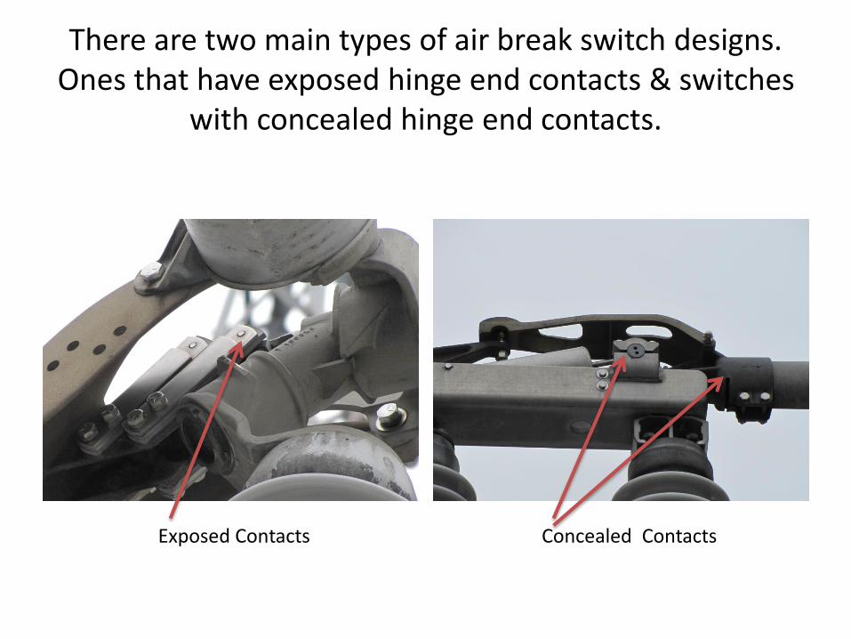
There are two main types of air break switch designs. Ones that have exposed hinge end contacts & switches
with concealed hinge end contacts.
Exposed Contacts Concealed Contacts
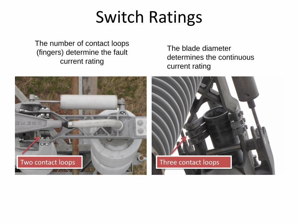
Switch Ratings
The number of contact loops
(fingers) determine the fault
current rating
The blade diameter
determines the continuous
current rating
Two contact loops Three contact loops

Jaw Contacts Must Be Flat To Carry Rated Current
The blades must be flat within ± 4° to maintain adequate contact compression
The allowable difference in elevation from one side of the blade contact to the other (dimension X) is 1/16” for each 1” of contact width. If contact width (A) is 3” then dimension (X) can be as much as 3/16” and still be within ± 4º tolerance.
Generic Switch Problems
• Heating
• Misaligned
• Not fully closed
• Stiff or difficult to operate

Heating Causes
• Not fully closed
• Poor contact compression or tension
• Dirty contact surfaces
Not fully closed
• Stops are out of adjustment & not in agreement.
• Cumulative friction from
– O-rings, bearings, pins, links & operators
• Loose hardware on structures
• Poor alignment
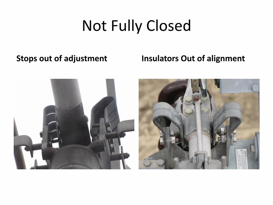
Not Fully Closed
Stops out of adjustment Insulators Out of alignment
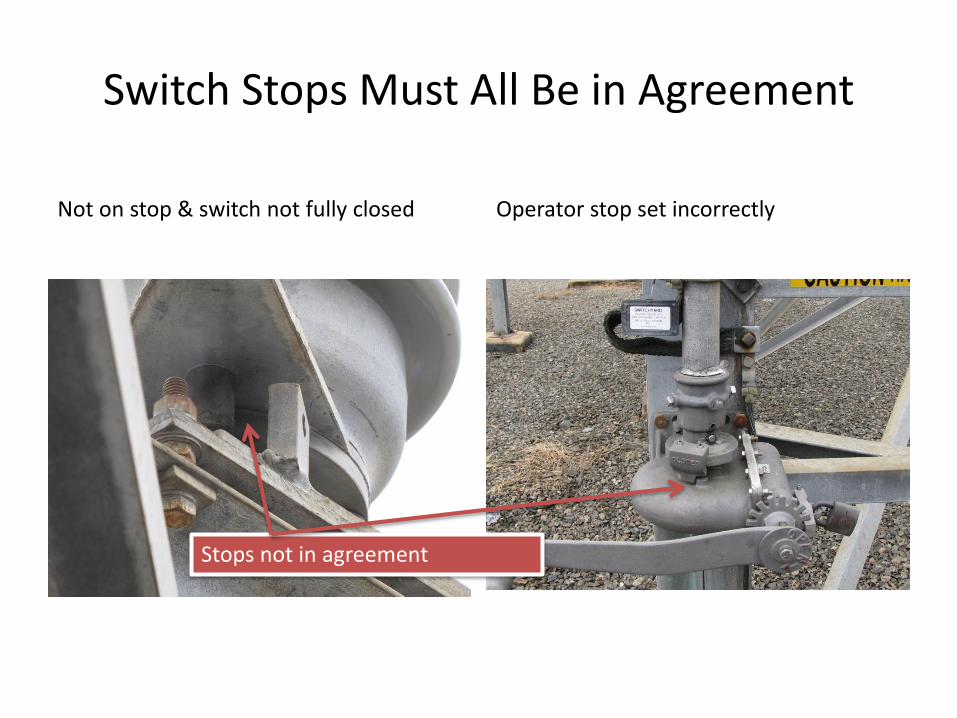
Switch Stops Must All Be in Agreement
Not on stop & switch not fully closed Operator stop set incorrectly
Stops not in agreement
1
5
3
4
2 6
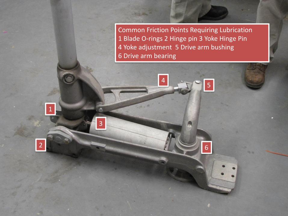
Common Friction Points Requiring Lubrication 1 Blade O-rings 2 Hinge pin 3 Yoke Hinge Pin4 Yoke adjustment 5 Drive arm bushing6 Drive arm bearing

Contact Fingers
Magnetic forces causes the loop designed contacts to press tighter against the blade during a fault.
Straight contacts require stiff backing springs to accomplish the same thing.

Jaw Contact CompressionTo determine contact compression measure distance between contact loops with switch open then with switch closed. The difference is the compression
The jaw contact loops may have springs to increase contact compression during normal load currents.

MORPAC Tools
MORPAC has developed proto type tool to measure jaw compression
Additional tool measures hinge contact tension
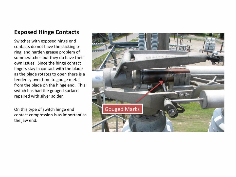
Exposed Hinge Contacts
Switches with exposed hinge end contacts do not have the sticking o-ring and harden grease problem of some switches but they do have their own issues. Since the hinge contact fingers stay in contact with the blade as the blade rotates to open there is a tendency over time to gouge metal from the blade on the hinge end. This switch has had the gouged surface repaired with silver solder.
On this type of switch hinge end contact compression is as important as the jaw end.
Gouged Marks
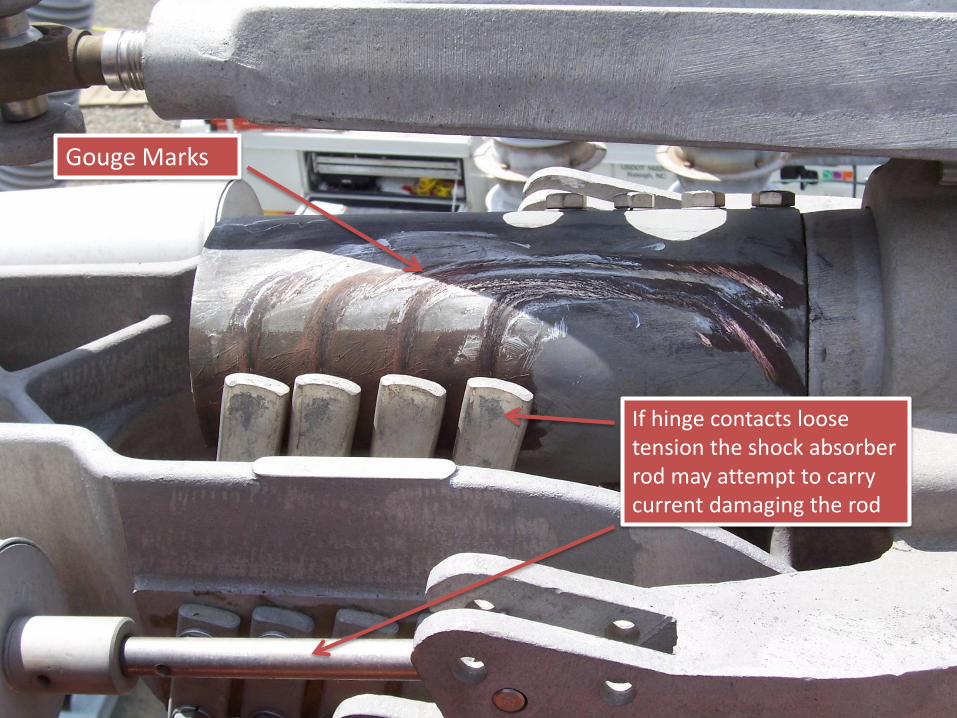
Gouge Marks
If hinge contacts loose tension the shock absorber rod may attempt to carry current damaging the rod

Stiff or Difficult to Operate
• Friction in the manual crank assembly
• Friction in the drive arm pins & clevises
– This can be a greater problem
• When machined parts with close tolerances are used
• When stain steel and brass are used in corrosive atmospheres
• Near the ocean
• Friction in the outboard bearing

A stiff or stuck disconnect or line switch may fail if excessive force is applied during opening or closing. The failure is usually in one of the following locations• Broken Hand Crank Mechanism•Broken Yoke•Broken Frame

Black Stains Indicate Water Ingress & Rubber O-ring Deterioration

Dry & Deteriorated O-ring With Water in Grease
Large circumference O-rings without lubrication create tremendous friction & prevent the blade from turning resulting in broken parts

Stiff or Difficult to Operate
Bad Bearings Stuck or dry O-rings

Blade to Hinge Current Transfer Designs
Current transfer from blade to hinge through threaded connection. Smaller diameter o-rings. This type less likely to stick and not rotate.
Current transfer from blade to hinge through smooth surface & contact fingers. Larger diameter o-rings. This type is more likely to stick and not rotate.

Misaligned
• Insulator stacks not plum– The most efficient way to plum insulator stacks is before the switch
live parts are installed find the center of all three stacks. Pull a string across all three stacks and align the insulator centers to the string. To ensure that the rotating insulator stack has no eccentricity check this stack rotated in the open and closed position. This can be the middle or tail end stack.

Switch Design Features
• The following slides highlights various switch design features along with weaknesses and known problems.
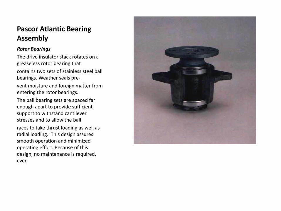
Pascor Atlantic Bearing Assembly
Rotor Bearings
The drive insulator stack rotates on a greaseless rotor bearing that
contains two sets of stainless steel ball bearings. Weather seals pre-
vent moisture and foreign matter from entering the rotor bearings.
The ball bearing sets are spaced far enough apart to provide sufficient support to withstand cantilever stresses and to allow the ball
races to take thrust loading as well as radial loading. This design assures smooth operation and minimized operating effort. Because of this design, no maintenance is required, ever.

The TTR line of switches have been manufactured by several companies. Some of the Siemens built switches will crack where the blade casting is clamped to the blade tube. The casting was redesigned and the metallurgy changed to eliminate the problem.
Cracked Casting
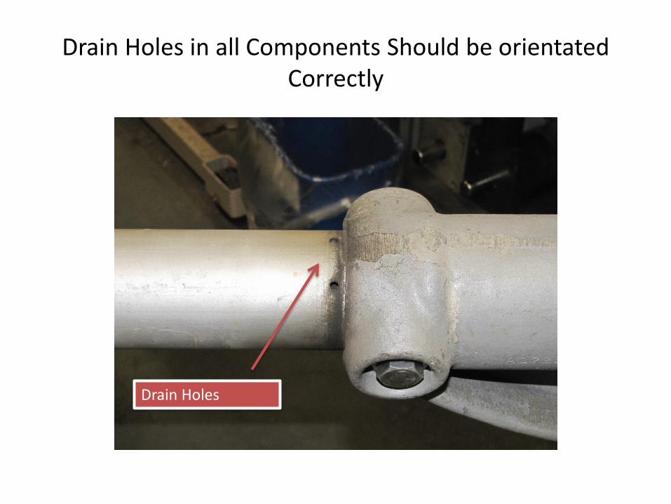
Drain Holes in all Components Should be orientated Correctly
Drain Holes

Problems have been found with Southern States switch bearings. The bearings are sealed but not stainless steel and have rusted solid. The sealing system is a felt ring and SS washer.
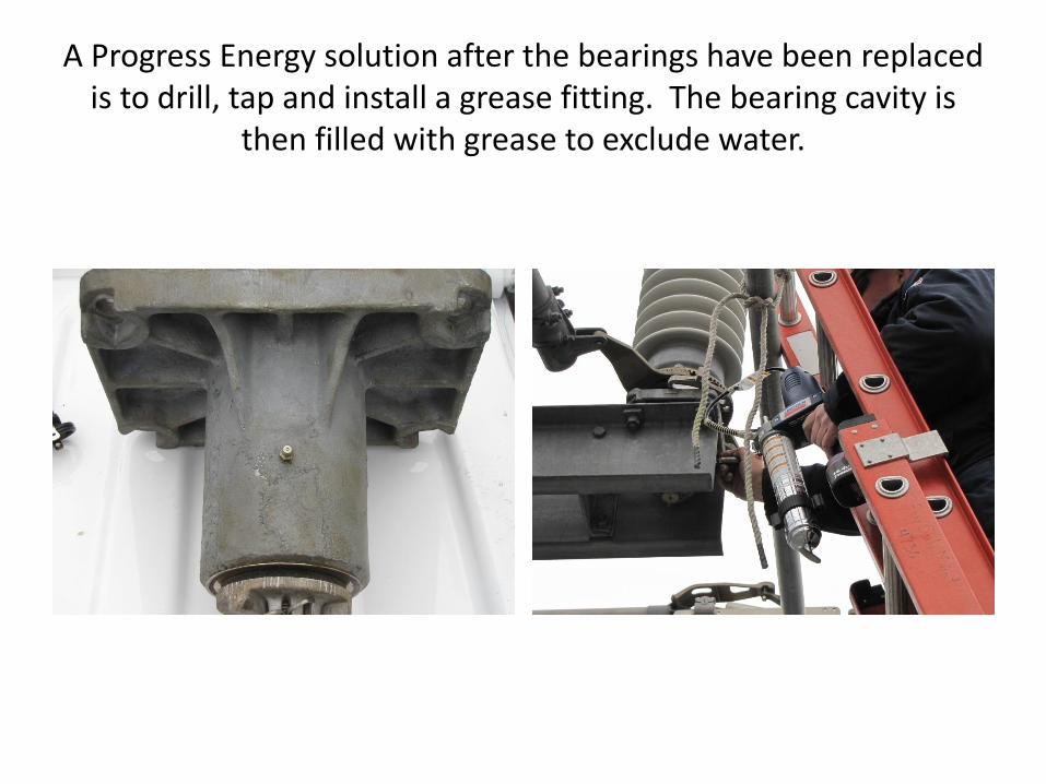
A Progress Energy solution after the bearings have been replaced is to drill, tap and install a grease fitting. The bearing cavity is
then filled with grease to exclude water.

Yoke Adjustment Adjust Individual Blades
Threaded Adjustment Setscrew Adjustment
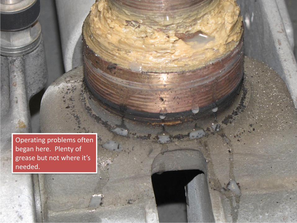
Operating problems often began here. Plenty of grease but not where it’s needed.

Blade Current Connection Styles
Blade casting with threaded connection current transfer design.
Blade casting with sliding finger pressure contacts and garter spring.
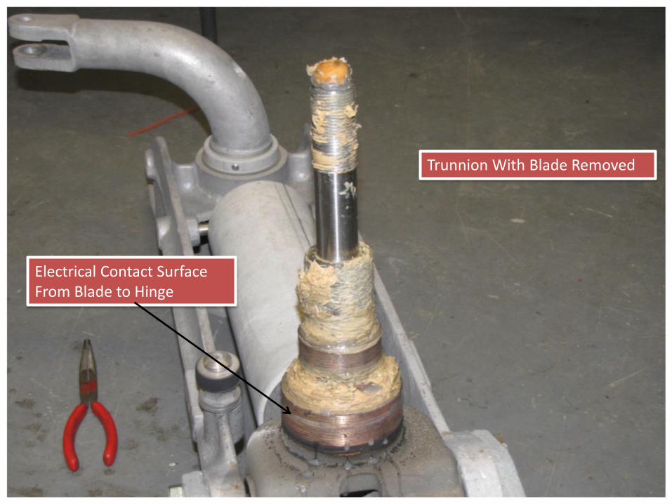
Trunnion With Blade Removed
Electrical Contact Surface From Blade to Hinge

After 20 years of exposure to the elements the grease no longer lubricates the o-ring. This results in stuck blade will not rotate. The grease is also contaminated with water.

Spring on one hinge pin to eliminate slack in the joint. There may be an insulating cap on one end of the spring to prevent the spring from carrying current.

ITE & Similar switches require Removing Plugs From Blades
Special tool for removing plug from blade
Plug contains o-rings needing replacement
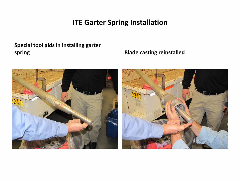
ITE Garter Spring Installation
Special tool aids in installing garter spring Blade casting reinstalled
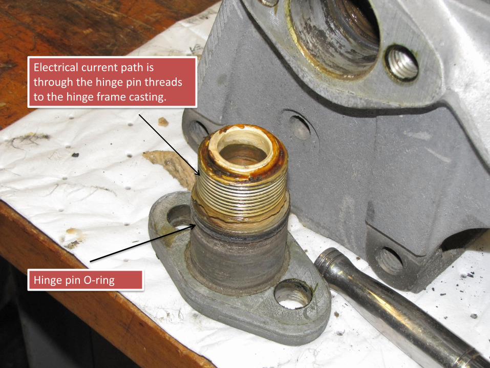
Electrical current path is through the hinge pin threads to the hinge frame casting.
Hinge pin O-ring
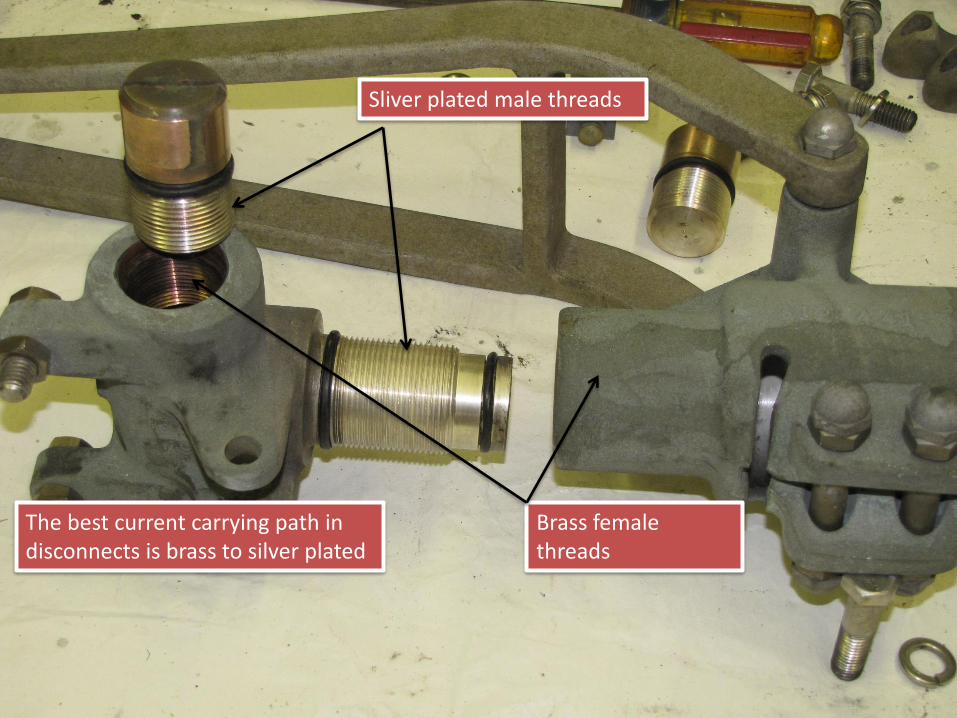
The best current carrying path in disconnects is brass to silver plated
Sliver plated male threads
Brass female threads
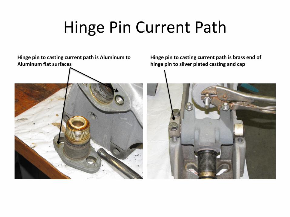
Hinge Pin Current Path
Hinge pin to casting current path is Aluminum to Aluminum flat surfaces
Hinge pin to casting current path is brass end of hinge pin to silver plated casting and cap
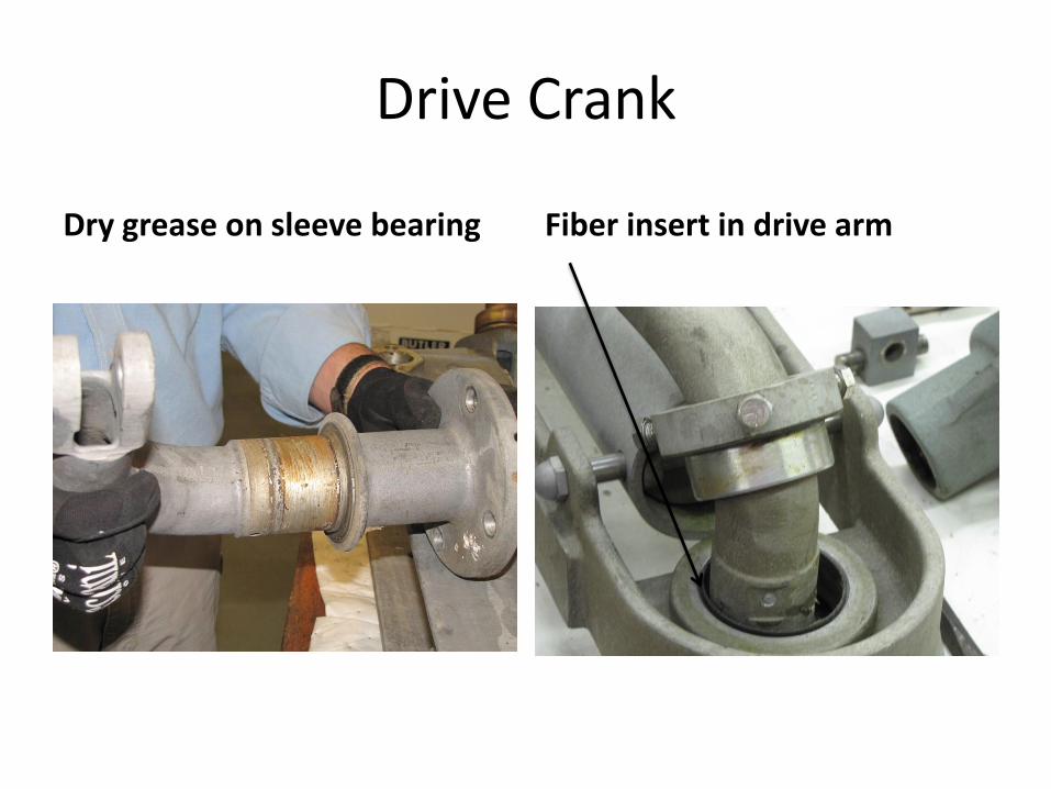
Drive Crank
Dry grease on sleeve bearing Fiber insert in drive arm