air compressor compresseur d’air compresor de aire · compresor de aire compresseur d’air...
TRANSCRIPT
C5512
www.deltaportercable.com
INSTRUCTIVO DE OPERACIÓN, CENTROS DE SERVICIO Y PÓLIZA DE GARANTÍA.
LÉASE ESTE INSTRUCTIVO ANTES DE USAR EL PRODUCTO.
Français : Page 29Español: Página 59
Air Compressor
Compresor de aire
Compresseur d’air
Instruction manualManuel d'instructionsManual de instrucciones
2- ENG
SAFETY GUIDELINES - DEFINITIONSThis manual contains information that is important for you to know and understand. This information relates to protecting YOUR SAFETY and PREVENTING EQUIPMENT PROBLEMS. To help you recognize this information, we use the symbols below. Please read the manual and pay attention to these symbols.
Indicates an imminently hazardous situation which, if not avoided, will result in death or serious injury.
Indicates a potentially hazardous situation which, if not avoided, may result in minor or moderate injury.
Indicates a potentially hazardous situation which, if not avoided, could result in death or serious injury.
Indicates a practice not related to personal injury which, if not avoided, may result in property damage.
IMPORTANT SAFETY INSTRUCTIONS
This product contains chemicals known to the State of California to cause cancer, and birth defects or other reproductive harm. Wash hands after handling.
Some dust contains chemicals known to the State of California to cause cancer, birth defects or other reproductive harm such as asbestos and lead in lead based paint.
To reduce the risk of injury, read the instruction manual.
SAVE THESE INSTRUCTIONS HAZARD
RISk OF ExPLOSION OR FIREWHAT CAN HAPPEN HOW TO PREVENT IT
• Itisnormalforelectricalcontacts within the motor and pressure switch to spark.
• Alwaysoperatethecompressorin a well ventilated area free of combustible materials, gasoline, or solvent vapors.
• Ifelectricalsparksfromcompressor come into contact with flammable vapors, they may ignite, causing fire or explosion.
• Ifsprayingflammablematerials,locate compressor at least 20' (6.1 m) away from spray area. An additional length of air hose may be required.
• Storeflammablematerialsin a secure location away from compressor.
3 - ENG
• Restrictinganyofthecom-pressor ventilation openings will cause serious overheat-ing and could cause fire.
• Neverplaceobjectsagainstor on top of compressor.
• Operatecompressorinanopenarea at least 12" (30.5 cm) away from any wall or obstruction that would restrict the flow of fresh air to the ventilation openings.
• Operatecompressorinaclean, dry well ventilated area. Do not operate unit in any confined area. Store indoors.
• Unattendedoperationofthisprod-uct could result in personal injury or property damage. To reduce the risk of fire, do not allow the com-pressor to operate unattended.
• Alwaysremaininattendancewiththe product when it is operating.
• Alwaysturnoffandunplugunit when not in use.
HAZARD
RISk TO BREATHING (ASPHYxIATION) WHAT CAN HAPPEN HOW TO PREVENT IT
• Thecompressedairdirectlyfromyour compressor is not safe for breathing. The air stream may contain carbon monoxide, toxic vapors, or solid particles from the air tank. Breathing these contaminants can cause serious injury or death.
• Neveruseairobtaineddirectlyfrom the compressor to supply air for human consumption. The compressor is not equipped with suitable filters and in-line safety equipment for human consumption.
• Exposuretochemicalsindustcreated by power sanding, sawing, grinding, drilling, and other construction activities may be harmful.
• Sprayedmaterialssuchaspaint,paint solvents, paint remover, insecticides, weed killers, may contain harmful vapors and poisons.
• Workinanareawithgoodcrossventilation. Read and follow the safety instructions provided on the label or safety data sheets for the materials you are spraying. Always use certified safety equipment: NIOSH/OSHA respiratory protection or properly fit ting face mask designed for use with your specific application.
4- ENG
HAZARD
RISk OF BURSTING
Air Tank: On February 26, 2002, the U.S. Consumer Product Safety Commission published Release # 02-108 concerning air compressor tank safety:Air compressor receiver tanks do not have an infinite life. Tank life is dependent upon several factors, some of which include operating conditions, ambient condi-tions, proper installations, field modifications, and the level of maintenance. The exact effect of these factors on air receiver life is difficult to predict.If proper maintenance procedures are not followed, internal corrosion to the inner wall of the air receiver tank can cause the air tank to unexpectedly rupture allowing pressurized air to suddenly and forcefully escape, posing risk of injury to consumers.Your compressor air tank must be removed from service by the end of the year shown on your tank warning label.The following conditions could lead to a weakening of the air tank, and result in a violent air tank explosion:
WHAT CAN HAPPEN HOW TO PREVENT IT• Failuretoproperlydraincondensed
water from air tank, causing rust and thinning of the steel air tank.
• Drainairtankdailyoraftereachuse.If air tank develops a leak, replace it immediately with a new air tank or replace the entire compressor.
• Modificationsorattemptedrepairs to the air tank.
• Neverdrillinto,weld,ormakeanymodifications to the air tank or its attachments. Never attempt to repair a damaged or leaking air tank. Replace with a new air tank.
• Unauthorizedmodificationsto the safety valve or any other components which control air tank pressure.
• Theairtankisdesignedtowithstandspecific operating pressures. Never make adjustments or parts substitutions to alter the factory set operating pressures.
Attachments & accessories:• Exceedingthepressurerat-
ing of air tools, spray guns, air operated accessories, tires, and other inflatables can cause them to explode or fly apart, and could result in serious injury.
• Followtheequipmentmanufacturersrecommendation and never exceed the maximum allowable pressure rating of attachments. Never use compressor to inflate small low pressure objects such as children’s toys, footballs, basketballs, etc.
5 - ENG
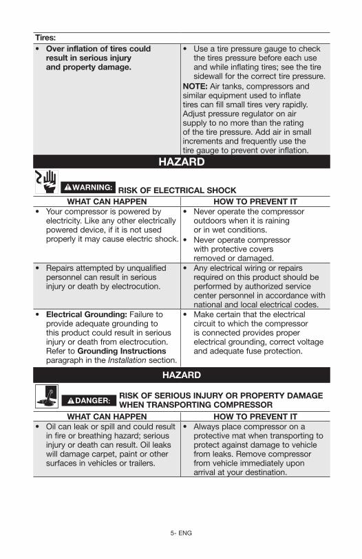
Tires:• Over inflation of tires could
result in serious injury and property damage.
• Useatirepressuregaugetocheckthe tires pressure before each use and while inflating tires; see the tire sidewall for the correct tire pressure.
NOTE: Air tanks, compressors and similar equipment used to inflate tires can fill small tires very rapidly. Adjust pressure regulator on air supply to no more than the rating of the tire pressure. Add air in small increments and frequently use the tire gauge to prevent over inflation.
HAZARD
RISk OF ELECTRICAL SHOCkWHAT CAN HAPPEN HOW TO PREVENT IT
• Yourcompressorispoweredbyelectricity. Like any other electrically powered device, if it is not used properly it may cause electric shock.
• Neveroperatethecompressoroutdoors when it is raining or in wet conditions.
• Neveroperatecompressorwith protective covers removed or damaged.
• Repairsattemptedbyunqualifiedpersonnel can result in serious injury or death by electrocution.
• Anyelectricalwiringorrepairsrequired on this product should be performed by authorized service center personnel in accordance with national and local electrical codes.
• Electrical Grounding: Failure to provide adequate grounding to this product could result in serious injury or death from electrocution. Refer to Grounding Instructions paragraph in the Installation section.
• Makecertainthattheelectricalcircuit to which the compressor is connected provides proper electrical grounding, correct voltage and adequate fuse protection.
HAZARD
RISk OF SERIOUS INjURY OR PROPERTY DAMAGE WHEN TRANSPORTING COMPRESSOR
WHAT CAN HAPPEN HOW TO PREVENT IT• Oilcanleakorspillandcouldresult
in fire or breathing hazard; serious injury or death can result. Oil leaks will damage carpet, paint or other surfaces in vehicles or trailers.
• Alwaysplacecompressoronaprotective mat when transporting to protect against damage to vehicle from leaks. Remove compressor from vehicle immediately upon arrival at your destination.
6- ENG
HAZARD
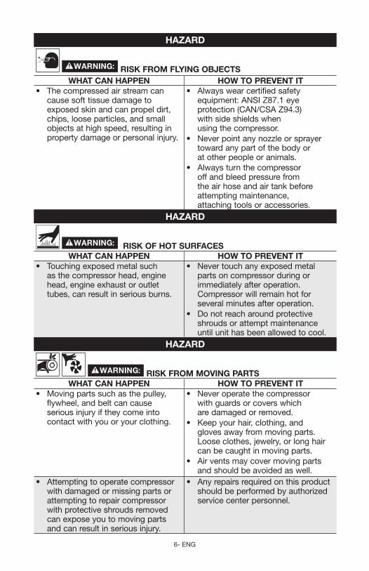
RISk FROM FLYING OBjECTSWHAT CAN HAPPEN HOW TO PREVENT IT
• Thecompressedairstreamcancause soft tissue damage to exposed skin and can propel dirt, chips, loose particles, and small objects at high speed, resulting in property damage or personal injury.
• Alwayswearcertifiedsafetyequipment: ANSI Z87.1 eye protection (CAN/CSA Z94.3) with side shields when using the compressor.
• Neverpointanynozzleorsprayertoward any part of the body or at other people or animals.
• Alwaysturnthecompressoroff and bleed pressure from the air hose and air tank before attempting maintenance, attaching tools or accessories.
HAZARD
RISk OF HOT SURFACESWHAT CAN HAPPEN HOW TO PREVENT IT
• Touchingexposedmetalsuchas the compressor head, engine head, engine exhaust or outlet tubes, can result in serious burns.
• Nevertouchanyexposedmetalparts on compressor during or immediately after operation. Compressor will remain hot for several minutes after operation.
• Donotreacharoundprotectiveshrouds or attempt maintenance until unit has been allowed to cool.
HAZARD
RISk FROM MOVING PARTSWHAT CAN HAPPEN HOW TO PREVENT IT
• Movingpartssuchasthepulley,flywheel, and belt can cause serious injury if they come into contact with you or your clothing.
• Neveroperatethecompressorwith guards or covers which are damaged or removed.
• Keepyourhair,clothing,andgloves away from moving parts. Loose clothes, jewelry, or long hair can be caught in moving parts.
• Airventsmaycovermovingpartsand should be avoided as well.
• Attemptingtooperatecompressorwith damaged or missing parts or attempting to repair compressor with protective shrouds removed can expose you to moving parts and can result in serious injury.
• Anyrepairsrequiredonthisproductshould be performed by authorized service center personnel.
7 - ENG
HAZARD
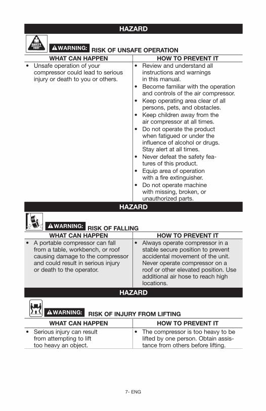
RISk OF UNSAFE OPERATIONWHAT CAN HAPPEN HOW TO PREVENT IT
• Unsafeoperationofyourcompressor could lead to se ri ous in ju ry or death to you or others.
• Reviewandunderstandallinstructions and warnings in this manual.
• Becomefamiliarwiththeoperationand con trols of the air compressor.
• Keepoperatingareaclearofallpersons, pets, and obstacles.
• Keepchildrenawayfromtheair compressor at all times.
• Donotoperatetheproductwhen fatigued or under the influence of alcohol or drugs. Stay alert at all times.
• Neverdefeatthesafetyfeatures of this prod uct.
• Equipareaofoperationwith a fire extinguisher.
• Donotoperatemachinewith missing, broken, or un au tho rized parts.
HAZARD
RISk OF FALLINGWHAT CAN HAPPEN HOW TO PREVENT IT
• Aportablecompressorcanfallfrom a table, workbench, or roof causing damage to the compressor and could result in serious injury or death to the operator.
• Alwaysoperatecompressorinastable secure position to prevent accidental movement of the unit. Never operate compressor on a roof or other elevated position. Use additional air hose to reach high locations.
HAZARD
RISk OF INjURY FROM LIFTING
WHAT CAN HAPPEN HOW TO PREVENT IT• Seriousinjurycanresult
from attempting to lift too heavy an object.
• Thecompressoristooheavytobelifted by one person. Obtain assis-tance from others before lifting.
8- ENG
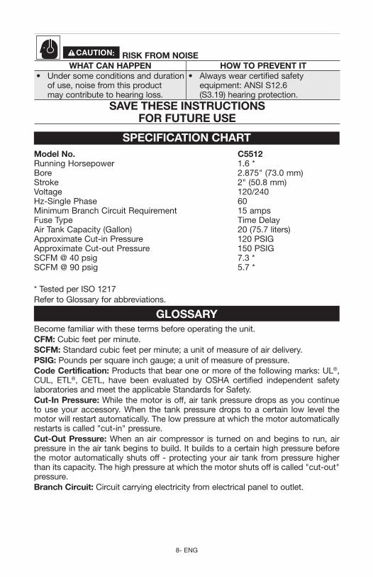
RISk FROM NOISEWHAT CAN HAPPEN HOW TO PREVENT IT
• Undersomeconditionsanddurationof use, noise from this product may contribute to hearing loss.
• Alwayswearcertifiedsafetyequipment: ANSI S12.6 (S3.19) hearing protection.
SAVE THESE INSTRUCTIONS FOR FUTURE USE
SPECIFICATION CHARTModel No. C5512Running Horsepower 1.6 *Bore 2.875" (73.0 mm)Stroke 2" (50.8 mm) Voltage 120/240Hz-Single Phase 60Minimum Branch Circuit Requirement 15 ampsFuse Type Time DelayAir Tank Capacity (Gallon) 20 (75.7 liters) Approximate Cut-in Pressure 120 PSIG Approximate Cut-out Pressure 150 PSIGSCFM @ 40 psig 7.3 * SCFM @ 90 psig 5.7 *
* Tested per ISO 1217Refer to Glossary for abbreviations.
GLOSSARYBecome familiar with these terms before operating the unit.CFM: Cubic feet per minute.SCFM: Standard cubic feet per minute; a unit of measure of air delivery.PSIG: Pounds per square inch gauge; a unit of measure of pressure.Code Certification: Products that bear one or more of the following marks: UL®, CUL, ETL®, CETL, have been evaluated by OSHA certified independent safety laboratories and meet the applicable Standards for Safety.Cut-In Pressure:Whilethemotorisoff,airtankpressuredropsasyoucontinuetouseyouraccessory.When the tankpressuredrops toacertain low level themotor will restart automatically. The low pressure at which the motor automatically restarts is called "cut-in" pressure.Cut-Out Pressure:Whenanaircompressor is turnedonandbegins to run,airpressure in the air tank begins to build. It builds to a certain high pressure before the motor automatically shuts off - protecting your air tank from pressure higher than its capacity. The high pressure at which the motor shuts off is called "cut-out" pressure.Branch Circuit: Circuit carrying electricity from electrical panel to outlet.
9 - ENG
DUTY CYCLEThis air compressor pump is capable of running continuously. However, to prolong the life of your air compressor, it is recommended that a 50%-75% average duty cycle be maintained; that is, the air compressor pump should not run more than 30-45 minutes in any given hour.
ACCESSORIESAccessories for this unit are available at the store the unit was purchased.
The use of any other accessory not recommended for use with this tool could be hazardous. Use only accessories rated equal to or higher than the rating of the air compressor.
ASSEMBLYTOOLS REqUIRED FOR ASSEMBLY1 - 9/16" socket or open end wrench1 - 1/2" socket or open end wrench
UNPACkINGRemove unit from carton and discard all packaging. NOTE: Save all parts bags.
This compressor was shipped with oil in the pump crankcase. Check oil before operating air compressor, see Check Oil under Maintenance.
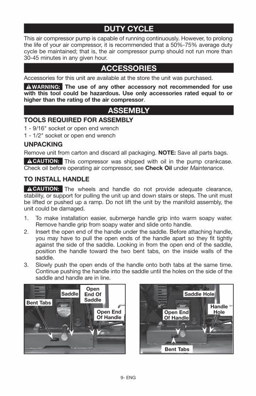
TO INSTALL HANDLE
The wheels and handle do not provide adequate clearance, stability, or support for pulling the unit up and down stairs or steps. The unit must be lifted or pushed up a ramp. Do not lift the unit by the manifold assembly, the unit could be damaged.
1. To make installation easier, submerge handle grip into warm soapy water. Remove handle grip from soapy water and slide onto handle.
2. Insert the open end of the handle under the saddle. Before attaching handle, you may have to pull the open ends of the handle apart so they fit tightly against the side of the saddle. Looking in from the open end of the saddle, position the handle toward the two bent tabs, on the inside walls of the saddle.
3. Slowly push the open ends of the handle onto both tabs at the same time. Continue pushing the handle into the saddle until the holes on the side of the saddle and handle are in line.
Saddle Hole
Handle Hole
Bent Tabs
Open End Of Handle
Bent Tabs
Saddle
Open End Of Handle
Open End Of Saddle
10- ENG
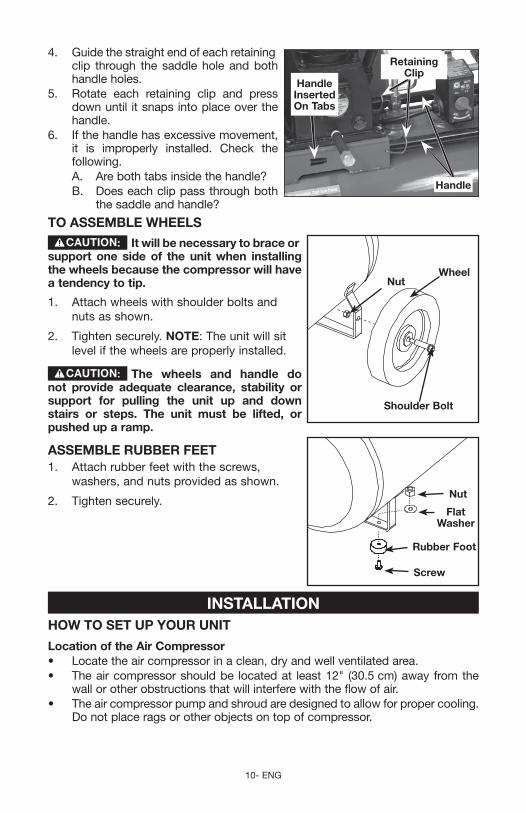
4. Guide the straight end of each retaining
Handle Inserted On Tabs
Retaining Clip
Handle
clip through the saddle hole and both handle holes.
5. Rotate each retaining clip and press down until it snaps into place over the handle.
6. If the handle has excessive movement, it is improperly installed. Check the following.
A. Are both tabs inside the handle? B. Does each clip pass through both
the saddle and handle?
TO ASSEMBLE WHEELS
It will be necessary to brace or
Wheel
Shoulder Bolt
Nut
support one side of the unit when installing the wheels because the compressor will have a tendency to tip.
1. Attach wheels with shoulder bolts and nuts as shown.
2. Tighten securely. NOTE: The unit will sit level if the wheels are properly installed.
The wheels and handle do not provide adequate clearance, stability or support for pulling the unit up and down stairs or steps. The unit must be lifted, or pushed up a ramp.
ASSEMBLE RUBBER FEET
Screw
Nut
Flat Washer
Rubber Foot
1. Attach rubber feet with the screws, washers, and nuts provided as shown.
2. Tighten securely.
INSTALLATIONHOW TO SET UP YOUR UNIT
Location of the Air Compressor• Locatetheaircompressorinaclean,dryandwellventilatedarea.• Theaircompressorshouldbe locatedat least12" (30.5cm)away fromthe
wall or other obstructions that will interfere with the flow of air. • Theaircompressorpumpandshroudaredesignedtoallowforpropercooling.
Do not place rags or other objects on top of compressor.
11 - ENG
GROUNDING INSTRUCTIONSRisk of Electrical Shock. In the event of a short circuit,
grounding reduces the risk of shock by providing an escape wire for the electric current. This air compressor must be properly grounded.
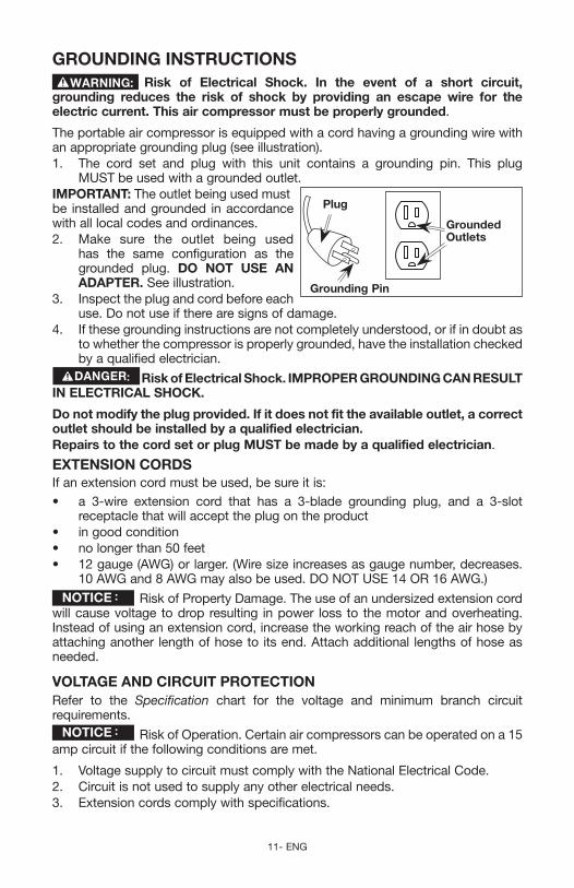
The portable air compressor is equipped with a cord having a grounding wire with an appropriate grounding plug (see illustration). 1. The cord set and plug with this unit contains a grounding pin. This plug
MUST be used with a grounded outlet. IMPORTANT: The outlet being used must
Grounded Outlets
Plug
Grounding Pin
be installed and grounded in accordance with all local codes and ordinances. 2. Make sure the outlet being used
has the same configuration as the grounded plug. DO NOT USE AN ADAPTER. See illustration.
3. Inspect the plug and cord before each use. Do not use if there are signs of damage.
4. If these grounding instructions are not completely understood, or if in doubt as to whether the compressor is properly grounded, have the installation checked by a qualified electrician.
Risk of Electrical Shock. IMPROPER GROUNDING CAN RESULT IN ELECTRICAL SHOCk.
Do not modify the plug provided. If it does not fit the available outlet, a correct outlet should be installed by a qualified electrician.Repairs to the cord set or plug MUST be made by a qualified electrician.
ExTENSION CORDSIf an extension cord must be used, be sure it is:• a 3wire extension cord that has a 3blade grounding plug, and a 3slot
receptacle that will accept the plug on the product• ingoodcondition• nolongerthan50feet• 12gauge(AWG)orlarger.(Wiresizeincreasesasgaugenumber,decreases.
10AWGand8AWGmayalsobeused.DONOTUSE14OR16AWG.)
Risk of Property Damage. The use of an undersized extension cord will cause voltage to drop resulting in power loss to the motor and overheating. Instead of using an extension cord, increase the working reach of the air hose by attaching another length of hose to its end. Attach additional lengths of hose as needed.
VOLTAGE AND CIRCUIT PROTECTIONRefer to the Specification chart for the voltage and minimum branch circuit requirements.
Risk of Operation. Certain air compressors can be operated on a 15 amp circuit if the following conditions are met.
1. Voltage supply to circuit must comply with the National Electrical Code.2. Circuit is not used to supply any other electrical needs.3. Extension cords comply with specifications.
12- ENG
4. Circuit is equipped with a 15 amp circuit breaker or 15 amp time delay fuse. NOTE: If compressor is connected to a circuit protected by fuses, use only
time delay fuses. Time delay fuses should be marked "D" in Canada and "T" in the US.
If any of the above conditions cannot be met, or if operation of the compressor repeatedly causes interruption of the power, it may be necessary to operate it from a 20 amp circuit. It is not necessary to change the cord set.
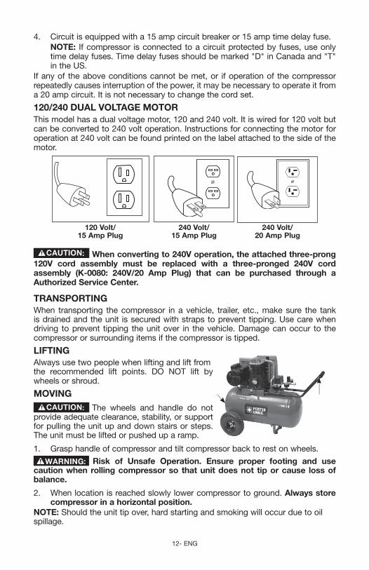
120/240 DUAL VOLTAGE MOTORThis model has a dual voltage motor, 120 and 240 volt. It is wired for 120 volt but can be converted to 240 volt operation. Instructions for connecting the motor for operation at 240 volt can be found printed on the label attached to the side of the motor.
120 Volt/ 15 Amp Plug
240 Volt/ 15 Amp Plug
240 Volt/ 20 Amp Plug
When converting to 240V operation, the attached three-prong 120V cord assembly must be replaced with a three-pronged 240V cord assembly (k-0080: 240V/20 Amp Plug) that can be purchased through a Authorized Service Center.
TRANSPORTINGWhen transporting thecompressor in a vehicle, trailer, etc.,makesure the tankis drained and the unit is secured with straps to prevent tipping. Use care when driving to prevent tipping the unit over in the vehicle. Damage can occur to the compressor or surrounding items if the compressor is tipped.
LIFTINGAlways use two people when lifting and lift from the recommended lift points. DO NOT lift by wheels or shroud.
MOVINGThe wheels and handle do not
provide adequate clearance, stability, or support for pulling the unit up and down stairs or steps. The unit must be lifted or pushed up a ramp.
1. Grasp handle of compressor and tilt compressor back to rest on wheels.
Risk of Unsafe Operation. Ensure proper footing and use caution when rolling compressor so that unit does not tip or cause loss of balance.
2. Whenlocationisreachedslowlylowercompressortoground.Always store compressor in a horizontal position.
NOTE: Should the unit tip over, hard starting and smoking will occur due to oil spillage.
13 - ENG
AIR DISTRIBUTION SYSTEM
Risk of Unsafe Operation. Unit cycles automatically when power is on. When servicing, you may be exposed to voltage sources, compressed air, or moving parts. Before servicing unit unplug or disconnect electrical supply to the air compressor, bleed tank of pressure, and allow the air compressor to cool.
IMPORTANT: The regulator assembly on the unit should be removed and a flex-ible coupling should be assembled to the pipe nipple for a plumbed-in air distri-bution system. Follow these instructions to correctly convert to a permanent air distribution system.
Risk of bursting. Plastic or PVC pipe is not designed for use with compressed air. Regardless of its indicated pressure rating, plastic pipe can burst from air pressure. Use only metal pipe for air distribution lines.
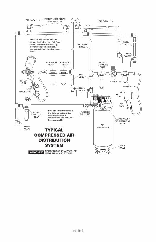
The next figure represents a typical air distribution system. The following are tips to remember when setting up the air compressor’s air distribution system. NOTE: Compressed air from oil lube air compressors will contain wa ter condensation and oil mist. Several drains, traps and filters will be needed to supply air without water (including aerosols) or oil to spray equipment, air tools and accessories requiring filtered air. Always read the in struc tions for the air tools and accessories being used.• Usepipethatisthesamesizeastheairtankoutlet.Pipingthatistoosmallwill
restrict the flow of air. • Ifpipingisover100'(30.5m)long,usethenextlargersize.• Bury underground lines below the frost line and avoid pockets where
condensation can gather and freeze. Apply pressure before underground lines are covered to make sure all pipe joints are free of leaks.
• Aflexiblecoupling isrecommendedtobe installedbetweenthepipenippleand main air distribution line to allow for vibration.
• Aseparateregulatorisrecommendedtocontroltheairpressure.Airpressurefrom the tank is usually to high for individual air driven tools.
• DONOTinstalllubricatorsbetweenthetankandanysprayequipment,airtoolor accessory requiring oil-free filtered air.
• Drainalltraps,filtersanddirtlegsdaily.
14- ENG
SPRAYGUN
AIRTOOL
DRAINLEGS
FILTER /MOISTURE
TRAP
DIRTLEGS
DRAINVALVES
DRAINVALVE
LUBRICATOR
REGULATOR
GLOBE VALVE /AIR DISCHARGE
VALVE
MAIN DISTRIBUTION AIR LINESSlope pipe in direction of air flow.Water condensate flows along bottom of pipe to drain legs, preventing it from entering feeder lines.
REGULATOR
BALLFILTER
FLEXIBLECOUPLING
DRAINVALVE
TYPICALCOMPRESSED AIR
DISTRIBUTIONSYSTEM
AIR FLOWAIR FLOW
FEEDER LINES SLOPEWITH AIR FLOW
AIR USAGELINES
AIRCOMPRESSOR
FILTER /MOISTURE
TRAP
FOR BEST PERFORMANCEthe distance between the compressor and the moisture trap should be as long as possible
RISK OF BURSTING. ALWAYS USE METAL PIPING AND FITTINGS.
DRAINVALVES
5 MICRONFILTER
.01 MICRONFILTER
15 - ENG
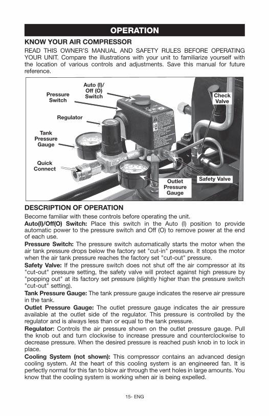
OPERATIONkNOW YOUR AIR COMPRESSORREAD THIS OWNER’S MANUAL AND SAFETY RULES BEFORE OPERATINGYOUR UNIT. Compare the illustrations with your unit to familiarize yourself with the location of various controls and adjustments. Save this manual for future reference.
Auto (I)/Off (O) Switch
Outlet Pressure Gauge
Pressure Switch
Tank Pressure
Gauge
quick Connect
Safety Valve
Check Valve
Regulator
DESCRIPTION OF OPERATIONBecome familiar with these controls before operating the unit.Auto(I)/Off(O) Switch: Place this switch in the Auto (I) position to provide automatic power to the pressure switch and Off (O) to remove power at the end of each use.Pressure Switch: The pressure switch automatically starts the motor when the air tank pressure drops below the factory set "cut-in" pressure. It stops the motor when the air tank pressure reaches the factory set "cut-out" pressure.Safety Valve: If the pressure switch does not shut off the air compressor at its "cut-out" pressure setting, the safety valve will protect against high pressure by "popping out" at its factory set pressure (slightly higher than the pressure switch "cut-out" setting).Tank Pressure Gauge: The tank pressure gauge indicates the reserve air pressure in the tank. Outlet Pressure Gauge: The outlet pressure gauge indicates the air pressure available at the outlet side of the regulator. This pressure is controlled by the regulator and is always less than or equal to the tank pressure. Regulator: Controls the air pressure shown on the outlet pressure gauge. Pull the knob out and turn clockwise to increase pressure and counterclockwise to decreasepressure.Whenthedesiredpressureisreachedpushknobintolockinplace.Cooling System (not shown): This compressor contains an advanced design cooling system. At the heart of this cooling system is an engineered fan. It is perfectly normal for this fan to blow air through the vent holes in large amounts. You know that the cooling system is working when air is being expelled.
16- ENG
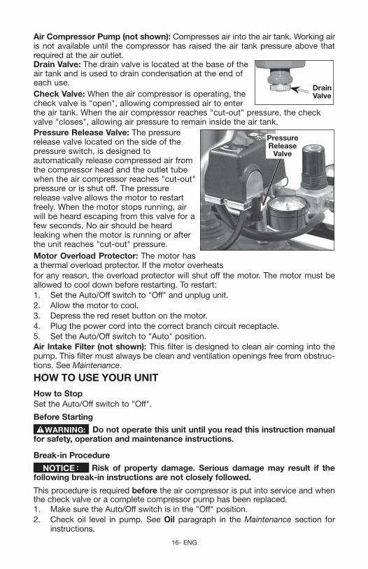
Air Compressor Pump (not shown):Compressesairintotheairtank.Workingairis not available until the compressor has raised the air tank pressure above that required at the air outlet.Drain Valve: The drain valve is located at the base of the
Drain Valve
air tank and is used to drain condensation at the end of each use. Check Valve:Whentheaircompressorisoperating,thecheck valve is "open", allowing compressed air to enter theairtank.Whentheaircompressorreaches"cutout"pressure,thecheckvalve "closes", allowing air pressure to remain inside the air tank.Pressure Release Valve: The pressure
Pressure Release
Valve
release valve located on the side of the pressure switch, is designed to automatically release compressed air from the compressor head and the outlet tube when the air compressor reaches "cut-out" pressure or is shut off. The pressure release valve allows the motor to restart freely.Whenthemotorstopsrunning,airwill be heard escaping from this valve for a few seconds. No air should be heard leaking when the motor is running or after the unit reaches "cut-out" pressure.Motor Overload Protector: The motor has a thermal overload protector. If the motor overheatsfor any reason, the overload protector will shut off the motor. The motor must be allowed to cool down before restarting. To restart:1. Set the Auto/Off switch to "Off" and unplug unit.2. Allow the motor to cool.3. Depress the red reset button on the motor.4. Plug the power cord into the correct branch circuit receptacle.5. Set the Auto/Off switch to "Auto" position.Air Intake Filter (not shown): This filter is designed to clean air coming into the pump. This filter must always be clean and ventilation openings free from obstruc-tions. See Maintenance.
HOW TO USE YOUR UNIT
How to StopSet the Auto/Off switch to "Off".
Before Starting
Do not operate this unit until you read this instruction manual for safety, operation and maintenance instructions.
Break-in Procedure
Risk of property damage. Serious damage may result if the following break-in instructions are not closely followed.
This procedure is required before the air compressor is put into service and when the check valve or a complete compressor pump has been replaced.1. Make sure the Auto/Off switch is in the "Off" position.2. Check oil level in pump. See Oil paragraph in the Maintenance section for
instructions.
17 - ENG
3. Plug the power cord into the correct branch circuit receptacle. (Refer to Voltage and Circuit Protection paragraph in the Installation section of this manual.)
4. Open the drain valve (counterclockwise) fully to permit air to escape and prevent air pressure build up in the air tank during the break-in period.
5. Move the Auto/Off switch to "Auto" position. The compressor will start.6. Run the compressor for 20 minutes. Make sure the drain valve is open and
there is minimal air pressure build-up in tank.7. After 20 minutes, close the drain valve by turning clockwise. The air receiver
will fill to "cut-out" pressure and the motor will stop. The compressor is now ready for use.
Before Each Start-Up1. Set the Auto/Off switch to "Off".2. Pull the regulator knob out and turn counterclockwise to set the outlet pressure
to zero.3. Attach hose and accessories.
Risk of unsafe operation. Firmly grasp air hose in hand when installing or disconnecting to prevent hose whip.
Risk of unsafe operation. Do not use damaged or worn accessories.
NOTE: The hose or accessory will require a quick connect plug if the air outlet is equipped with a quick connect socket.
Risk of Bursting. Too much air pressure causes a hazardous risk of bursting. Check the manufacturer’s maximum pressure rating for air tools and accessories. The regulator outlet pressure must never exceed the maximum pressure rating.
Risk of property damage. Compressed air from the unit may contain wa ter condensation and oil mist. Do not spray un fil tered air at an item that could be damaged by moisture. Some air tools and accessories may require filtered air. Read the in struc tions for the air tools and accessories.
How to Start1. Set the Auto/Off switch to "Auto" and allow tank pressure to build. Motor will stop
when tank pressure reaches "cut-out" pressure.2. Pulltheregulatorknoboutandturnclockwisetoincreasepressure.Whenthe
desired pressure is reached push knob in to lock in place.
If any unusual noise or vibration is noticed, stop the compressor immediately and have it checked by a trained service technician.
The compressor is ready for use.
18- ENG
MAINTENANCECUSTOMER RESPONSIBILITIES
Bef
ore
each
use
Dai
ly o
r af
ter
each
use
Eve
ry 8
ho
urs
Eve
ry 4
0 ho
urs
Eve
ry 1
00
hour
s
Eve
ry 1
60
hour
s
Year
ly
See
tan
k w
arni
ng la
bel
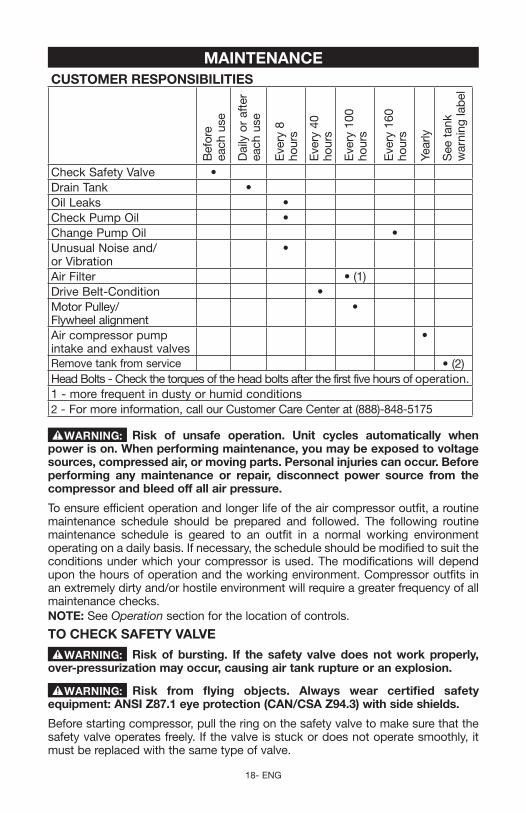
Check Safety Valve •Drain Tank •Oil Leaks •Check Pump Oil •Change Pump Oil •Unusual Noise and/or Vibration
•
Air Filter • (1)Drive Belt-Condition •Motor Pulley/Flywheel alignment
•
Air compressor pump intake and exhaust valves
•
Remove tank from service • (2)Head Bolts - Check the torques of the head bolts after the first five hours of operation.1 - more frequent in dusty or humid conditions2 - For more information, call our Customer Care Center at (888)-848-5175
Risk of unsafe operation. Unit cycles automatically when power is on. When performing maintenance, you may be exposed to voltage sources, compressed air, or moving parts. Personal injuries can occur. Before performing any maintenance or repair, disconnect power source from the compressor and bleed off all air pressure.
To ensure efficient operation and longer life of the air compressor outfit, a routine maintenance schedule should be prepared and followed. The following routine maintenance schedule is geared to an outfit in a normal working environment operating on a daily basis. If necessary, the schedule should be modified to suit the conditions under which your compressor is used. The modifications will depend upon the hours of operation and the working environment. Compressor outfits in an extremely dirty and/or hostile environment will require a greater frequency of all maintenance checks.NOTE: See Operation section for the location of controls.
TO CHECk SAFETY VALVE
Risk of bursting. If the safety valve does not work properly, over-pressurization may occur, causing air tank rupture or an explosion.
Risk from flying objects. Always wear certified safety equipment: ANSI Z87.1 eye protection (CAN/CSA Z94.3) with side shields.
Before starting compressor, pull the ring on the safety valve to make sure that the safety valve operates freely. If the valve is stuck or does not operate smoothly, it must be replaced with the same type of valve.
19 - ENG
TO DRAIN TANkRisk of unsafe operation. Air tanks contain high pressure air.
keep face and other body parts away from outlet of drain. Use eye protection [ANSI Z87.1 (CAN/CSA Z94.3)] when draining as debris can be kicked up into face.
Risk from noise. Use ear protection (ANSI S12.6 (S3.19) as air flow noise is loud when draining.
NOTE: All compressed air systems generate condensate that accumulates in any drain point (e.g., tanks, filter, aftercoolers, dryers). This condensate contains lubricating oil and/or substances which may be regulated and must be disposed of in accordance with local, state, and federal laws and regulations.1. Set the Auto/Off lever to "Off" and unplug unit.2. Pull the regulator knob out and turn counterclockwise to set the outlet pres-
sure to zero.3. Remove the air tool or accessory.4. Pull ring on safety valve allowing air to bleed from the tank until tank pressure
is approximately 20 psi. Release safety valve ring.5. Drain water from air tank by opening drain valve (counterclockwise) on bottom
of tank.
Risk of Bursting. Water will condense in the air tank. If not drained, water will corrode and weaken the air tank causing a risk of air tank rupture.
Risk of Property Damage. Drain water from air tank may contain oil and rust which can cause stains.
6. After the water has been drained, close the drain valve (clockwise). The air compressor can now be stored.
NOTE: If drain valve is plugged, release all air pressure. The valve can then be removed, cleaned, the reinstalled.
OILRisk of property damage. Use air compressor oil only. Multi-weight
automotive engine oils like 10W30 should not be use in air compressors. Theyleave carbon deposits on critical components, thus reducing performance and compressor life.
NOTE: Use 30W compressor oil or a heavy duty SAE 30W, nondetergent, SFgrade or better oil. DO NOT use multi-weight automotive engine oils, they will reduce compressor life. Under extreme winter condition use SAE-10 weight oil.NOTE: Crankcase oil capacity is approximately 16 fluid ounces (0.47 L).
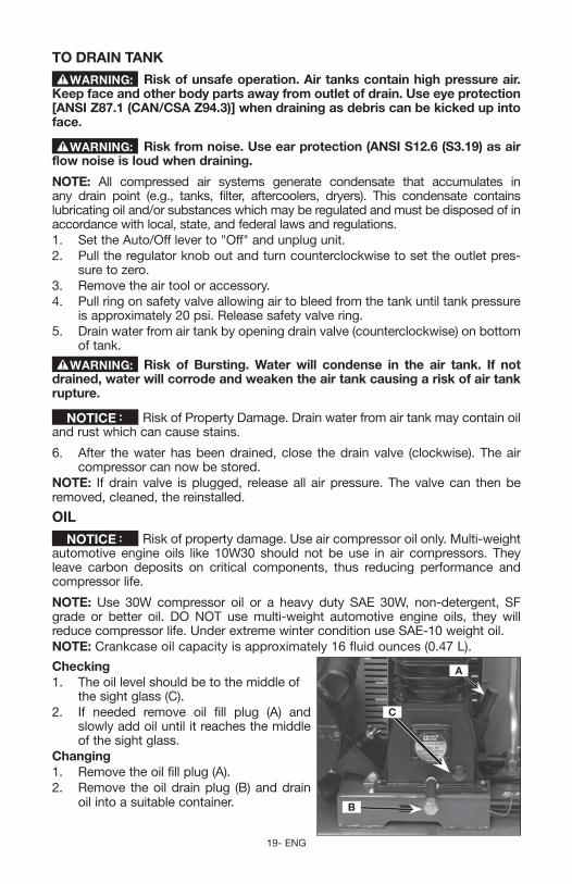
Checking1. The oil level should be to the middle of
C
B
A
the sight glass (C).2. If needed remove oil fill plug (A) and
slowly add oil until it reaches the middle of the sight glass.
Changing1. Remove the oil fill plug (A). 2. Remove the oil drain plug (B) and drain
oil into a suitable container.
20- ENG
3. Replace the oil drain plug (B) and tighten securely.4. Slowly add compressor oil until the oil level is in the middle of the sightglass
(C). NOTE:Whenfillingthecrankcase,theoilflowsveryslowlyintothepump.If the oil is added too quickly, it will overflow and appear to be full.
Risk of property damage. Overfilling with oil will cause premature compressor failure. Do not overfill.
5. Replace oil fill plug (A) and tighten securely.
AIR FILTER - INSPECTION AND REPLACEMENT
Hot surfaces. Risk of burn. Compressor heads are exposed when filter cover is removed. Allow compressor to cool prior to servicing.
keep the air filter clean at all times. Do not operate the air compressor with the air filter removed.
A dirty air filter will not allow the compressor pump to operate at full capacity. Before using the compressor pump, check the air filter to make sure it is clean and in place.If it is dirty, replace it with a new filter.1. Using a pair of needle nose pliers or a screwdriver pull or pry out the old
filter and carefully clean the filter area. 2. Push the new air filter in place. IMPORTANT: Do not operate the compressor with the air filter removed.
BELT - REPLACEMENT
Risk of unsafe operation. Serious injury or damage may occur if parts of the body or loose items get caught in moving parts. Never operate the outfit with the belt guard removed. The belt guard should be removed only when the air compressor power is disconnected.
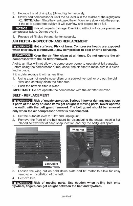
1. Set the Auto/Off lever to "Off" and unplug unit.2. Remove the front of the belt guard by disengaging the snaps. Insert a flat
bladed screwdriver at each snap location and pry the beltguard apart.
Belt Guard
Wing Nut
3. Loosen the wing nut on hold down plate and tilt motor to allow for easy removal or installation of the belt.
4. Remove belt.
Risk of moving parts. Use caution when rolling belt onto flywheel, fingers can get caught between the belt and flywheel.
21 - ENG
5. Replace belt. NOTE: The belt must be centered over the grooves on the flywheel and motor pulley.
6. Turn the wing nut on the hold down plate until it makes contact with the washer, plus one additional turn.
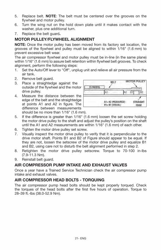
7. Replace the belt guard.MOTOR PULLEY/FLYWHEEL ALIGNMENTNOTE: Once the motor pulley has been moved from its factory set location, the grooves of the flywheel and pulley must be aligned to within 1/16" (1.6 mm) to prevent excessive belt wear.The air compressor flywheel and motor pulley must be in-line (in the same plane) within 1/16" (1.6 mm) to assure belt retention within flywheel belt grooves. To check alignment, perform the following steps:1. Set the Auto/Off lever to "Off", unplug unit and relieve all air pressure from the
air tank.2. Remove belt guard.3. Place a straightedge against the
outside of the flywheel and the motor drive pulley.
4. Measure the distance between the edge of the belt and the straightedge at points A1 and A2 in figure. The difference between measurements should be no more than 1/16" (1.6 mm).
5. If the difference is greater than 1/16" (1.6 mm) loosen the set screw holding the motor drive pulley to the shaft and adjust the pulley’s position on the shaft until the A1 and A2 measurements are within 1/16" (1.6 mm) of each other.
6. Tighten the motor drive pulley set screw. 7. Visually inspect the motor drive pulley to verify that it is perpendicular to the
drive motor shaft. Points B1 and B2 of Figure should appear to be equal. If they are not, loosen the setscrew of the motor drive pulley and equalize B1 and B2, using care not to disturb the belt alignment performed in step 2.
8. Retighten the motor drive pulley setscrew. Torque to 70-100 in-lbs (7.9-11.3 Nm).
9. Reinstall belt guard.
AIR COMPRESSOR PUMP INTAkE AND ExHAUST VALVESOnce a year have a Trained Service Technician check the air compressor pump intake and exhaust valves.
AIR COMPRESSOR HEAD BOLTS - TORqUING The air compressor pump head bolts should be kept properly torqued. Check the torques of the head bolts after the first five hours of operation. Torque to 28–39 ft.-lbs (38.0-52.9 Nm).
22- ENG
SERVICE AND ADjUSTMENTSALL MAINTENANCE AND REPAIR OPERATIONS NOT LISTED MUST BE PERFORMED BY TRAINED SERVICE TECHNICIAN.
Risk of Unsafe Operation. Unit cycles automatically when power is on. When servicing, you may be exposed to voltage sources, compressed air, or moving parts. Before servicing unit unplug or disconnect electrical supply to the air compressor, bleed tank of pressure, and allow the air compressor to cool.
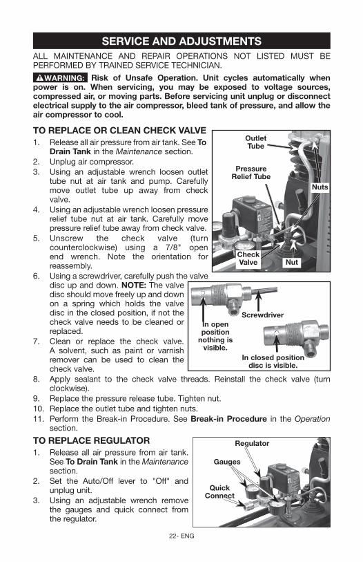
TO REPLACE OR CLEAN CHECk VALVE 1. Release all air pressure from air tank. See To Outlet
Tube
Nut
Nuts
Check Valve
Pressure Relief Tube
Drain Tank in the Maintenance section.2. Unplug air compressor.3. Using an adjustable wrench loosen outlet
tube nut at air tank and pump. Carefully move outlet tube up away from check valve.
4. Using an adjustable wrench loosen pressure relief tube nut at air tank. Carefully move pressure relief tube away from check valve.
5. Unscrew the check valve (turn counterclockwise) using a 7/8" open end wrench. Note the orientation for reassembly.
6. Using a screwdriver, carefully push the valve disc up and down. NOTE: The valve
In closed position disc is visible.
In open position
nothing is visible.
Screwdriver
disc should move freely up and down on a spring which holds the valve disc in the closed position, if not the check valve needs to be cleaned or replaced.
7. Clean or replace the check valve. A solvent, such as paint or varnish remover can be used to clean the check valve.
8. Apply sealant to the check valve threads. Reinstall the check valve (turn clockwise).
9. Replace the pressure release tube. Tighten nut.10. Replace the outlet tube and tighten nuts.11. Perform the Break-in Procedure. See Break-in Procedure in the Operation
section.
TO REPLACE REGULATOR1. Release all air pressure from air tank.
Gauges
quick Connect
Regulator
See To Drain Tank in the Maintenance section.
2. Set the Auto/Off lever to "Off" and unplug unit.
3. Using an adjustable wrench remove the gauges and quick connect from the regulator.
23 - ENG
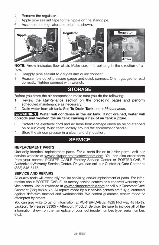
4. Remove the regulator.5. Apply pipe sealant tape to the nipple on the standpipe.6. Assemble the regulator and orient as shown.
RegulatorNipple
Regulator
Arrow
NOTE: Arrow indicates flow of air. Make sure it is pointing in the direction of air flow.7. Reapply pipe sealant to gauges and quick connect. 8. Reassemble outlet pressure gauge and quick connect. Orient gauges to read
correctly. Tighten connect with wrench.
STORAGEBefore you store the air compressor, make sure you do the following:1. Review the Maintenance section on the preceding pages and perform
scheduled maintenance as necessary. 2. Drain water from air tank. See To Drain Tank under Maintenance.
Water will condense in the air tank. If not drained, water will corrode and weaken the air tank causing a risk of air tank rupture.
3. Protect the electrical cord and air hose from damage (such as being stepped onorrunover).Windthemlooselyaroundthecompressorhandle.
4. Store the air compressor in a clean and dry location.
SERVICEREPLACEMENT PARTSREPLACEMENT PARTSUse only identical replacement parts. For a parts list or to order parts, visit our service website at www.deltaportercableservicenet.com. You can also order parts from your nearest PORTER-CABLE Factory Service Center or PORTER-CABLE AuthorizedWarrantyServiceCenter.Or,youcancallourCustomerCareCenterat(888) 848-5175.
SERVICE AND REPAIRSAll quality tools will eventually require servicing and/or replacement of parts. For infor-mation about PORTER-CABLE, its factory service centers or authorized warranty ser-vice centers, visit our website at www.deltaportercable.com or call our Customer Care Center at (888) 848-5175. All repairs made by our service centers are fully guaranteed against defectivematerial andworkmanship.Wecannotguarantee repairsmadeorattempted by others.You can also write to us for information at PORTER-CABLE, 4825 Highway 45 North, Jackson, Tennessee 38305 - Attention: Product Service. Be sure to include all of the information shown on the nameplate of your tool (model number, type, serial number, etc.).
24- ENG
ACCESSORIESSince accessories, other than those offered by PORTER-CABLE, have
not been tested with this product, use of such accessories with this tool could be haz-ardous. To reduce the risk of injury, only PORTER-CABLE recommended accessories should be used with this product.
A complete line of accessories is available from your PORTER-CABLE Factory Service CenteroraPORTERCABLEAuthorizedWarrantyServiceCenter.PleasevisitourWebSite www.deltaportercable.com for a catalog or for the name of your nearest supplier.
TROUBLESHOOTING
Risk of Unsafe Operation. Unit cycles automatically when power is on. When servicing, you may be exposed to voltage sources, compressed air, or moving parts. Before servicing unit unplug or disconnect electrical supply to the air compressor, bleed tank of pressure, and allow the air compressor to cool.
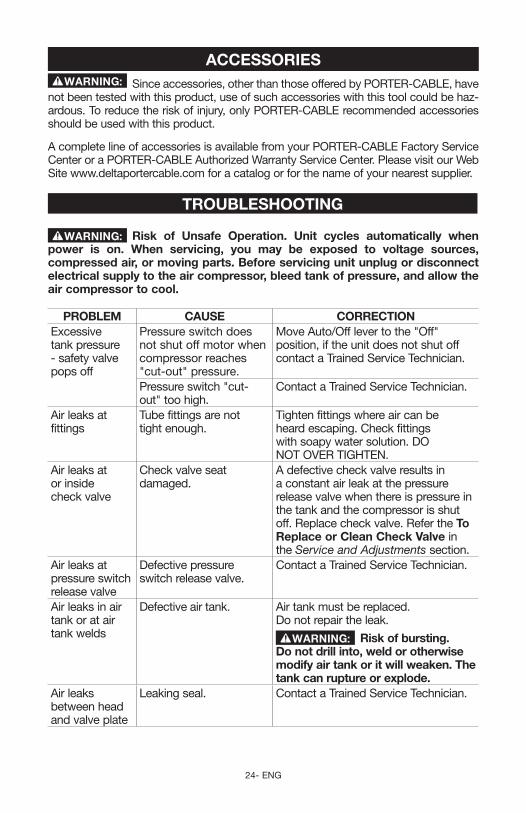
PROBLEM CAUSE CORRECTIONExcessive tank pressure - safety valve pops off
Pressure switch does not shut off motor when compressor reaches "cut-out" pressure.
Move Auto/Off lever to the "Off" position, if the unit does not shut off contact a Trained Service Technician.
Pressure switch "cut-out" too high.
Contact a Trained Service Technician.
Air leaks at fittings
Tube fittings are not tight enough.
Tighten fittings where air can be heard escaping. Check fittings with soapy water solution. DO NOT OVER TIGHTEN.
Air leaks at or inside check valve
Check valve seat damaged.
A defective check valve results in a constant air leak at the pressure release valve when there is pressure in the tank and the compressor is shut off. Replace check valve. Refer the To Replace or Clean Check Valve in the Service and Adjustments section.
Air leaks at pressure switch release valve
Defective pressure switch release valve.
Contact a Trained Service Technician.
Air leaks in air tank or at air tank welds
Defective air tank. Air tank must be replaced. Do not repair the leak.
Risk of bursting.Do not drill into, weld or otherwise modify air tank or it will weaken. The tank can rupture or explode.
Air leaks between head and valve plate
Leaking seal. Contact a Trained Service Technician.
25 - ENG
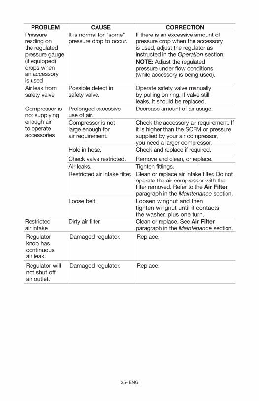
PROBLEM CAUSE CORRECTIONPressure reading on the regulated pressure gauge (if equipped) drops when an accessory is used
It is normal for "some" pressure drop to occur.
If there is an excessive amount of pressure drop when the accessory is used, adjust the regulator as instructed in the Operation section.NOTE: Adjust the regulated pressure under flow conditions (while accessory is being used).
Air leak from safety valve
Possible defect in safety valve.
Operate safety valve manually by pulling on ring. If valve still leaks, it should be replaced.
Compressor is not supplying enough air to operate accessories
Prolonged excessive use of air.
Decrease amount of air usage.
Compressor is not large enough for air requirement.
Check the accessory air requirement. If it is higher than the SCFM or pressure supplied by your air compressor, you need a larger compressor.
Hole in hose. Check and replace if required.
Check valve restricted. Remove and clean, or replace.Air leaks. Tighten fittings. Restricted air intake filter. Clean or replace air intake filter. Do not
operate the air compressor with the filter removed. Refer to the Air Filter paragraph in the Maintenance section.
Loose belt. Loosen wingnut and then tighten wingnut until it contacts the washer, plus one turn.
Restricted air intake
Dirty air filter. Clean or replace. See Air Filter paragraph in the Maintenance section.
Regulator knob has continuous air leak.
Damaged regulator. Replace.
Regulator will not shut off air outlet.
Damaged regulator. Replace.
26- ENG
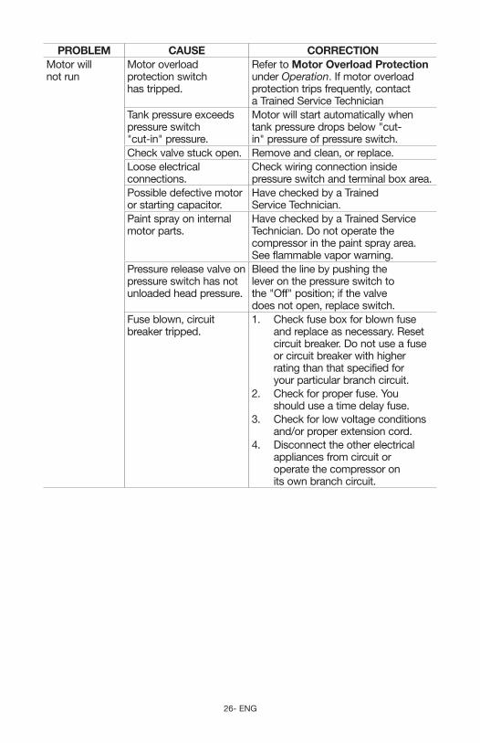
PROBLEM CAUSE CORRECTIONMotor will not run
Motor overload protection switch has tripped.
Refer to Motor Overload Protection under Operation. If motor overload protection trips frequently, contact a Trained Service Technician
Tank pressure exceeds pressure switch "cut-in" pressure.
Motor will start automatically when tank pressure drops below "cut-in" pressure of pressure switch.
Check valve stuck open. Remove and clean, or replace.Loose electrical connections.
Check wiring connection inside pressure switch and terminal box area.
Possible defective motor or starting capacitor.
Have checked by a Trained Service Technician.
Paint spray on internal motor parts.
Have checked by a Trained Service Technician. Do not operate the compressor in the paint spray area. See flammable vapor warning.
Pressure release valve on pressure switch has not unloaded head pressure.
Bleed the line by pushing the lever on the pressure switch to the "Off" position; if the valve does not open, replace switch.
Fuse blown, circuit breaker tripped.
1. Check fuse box for blown fuse and replace as necessary. Reset circuit breaker. Do not use a fuse or circuit breaker with higher rating than that specified for your particular branch circuit.
2. Check for proper fuse. You should use a time delay fuse.
3. Check for low voltage conditions and/or proper extension cord.
4. Disconnect the other electrical appliances from circuit or operate the compressor on its own branch circuit.
27 - ENG
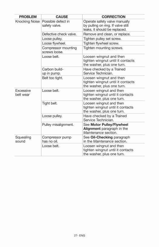
PROBLEM CAUSE CORRECTIONKnockingNoise Possible defect in
safety valve.Operate safety valve manually by pulling on ring. If valve still leaks, it should be replaced.
Defective check valve. Remove and clean, or replace.Loose pulley. Tighten pulley set screw.Loose flywheel. Tighten flywheel screw.Compressor mounting screws loose.
Tighten mounting screws.
Loose belt. Loosen wingnut and then tighten wingnut until it contacts the washer, plus one turn.
Carbon build-up in pump.
Have checked by a Trained Service Technician.
Belt too tight. Loosen wingnut and then tighten wingnut until it contacts the washer, plus one turn.
Excessive belt wear
Loose belt. Loosen wingnut and then tighten wingnut until it contacts the washer, plus one turn.
Tight belt. Loosen wingnut and then tighten wingnut until it contacts the washer, plus one turn.
Loose pulley. Have checked by a Trained Service Technician.
Pulley misalignment. See Motor Pulley/Flywheel Alignment paragraph in the Maintenance section.
Squealing sound
Compressor pump has no oil.
See Oil-Checking paragraph in the Maintenance section.
Loose belt. Loosen wingnut and then tighten wingnut until it contacts the washer, plus one turn.
28- ENG
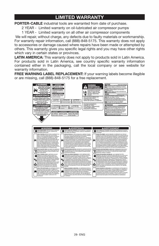
LIMITED WARRANTYPORTER-CABLE industrial tools are warranted from date of purchase. 2 YEAR - Limited warranty on oil-lubricated air compressor pumps 1 YEAR - Limited warranty on all other air compressor componentsWewillrepair,withoutcharge,anydefectsduetofaultymaterialsorworkmanship.For warranty repair information, call (888)-848-5175. This warranty does not apply to accessories or damage caused where repairs have been made or attempted by others. This warranty gives you specific legal rights and you may have other rights which vary in certain states or provinces.LATIN AMERICA: This warranty does not apply to products sold in Latin America. For products sold in Latin America, see country specific warranty information contained either in the packaging, call the local company or see website for warranty information.FREE WARNING LABEL REPLACEMENT: If your warning labels become illegible or are missing, call (888)-848-5175 for a free replacement.
HOT SURFACE. RISK OF BURNS.DO NOT TOUCH.
SUPERFICIE CALIENTE.RIESGO DE QUEMADURAS. NO TOCAR.
SURFACE TRÈS CHAUDE.RISQUES DE BRÛLURES.NE PAS TOUCHER.
WARNING ADVERTENCIA AVERTISSEMENT
ATTENTION PRECAUCIÓNSee owner's manual for
break-in procedures.Consultez le manuel de
l'utilisateur pour lesprocédures de rodage.
Para el procedimiento deasentado de la maquina,ver manual del operario.
PRECAUCIÓN CAUTION ATTENTION Fill crankcase with oil before running compressor.
Liene el cárter con aceite antes de arrancar el compresor.
Remplissez le carter d'huile avant de mettre le compresseur en marche.
ATTENTION
LISEZ LE MANUEL DU PROPRIÉTAIRE POUR LES INFORMATIONS COMPLÈTES D'ENTRETIEN ET D'UTILISATION.
UTILISEZ DE L'HUILE POUR COMPRESSEURS DE POIDS 30 OUUNE HUILE NON-DÉTERGENTE, DE HAUTE TENUE SAE 30W, DECLASSE SF OU PLUS ÉLEVÉE. N'UTILISEZ PAS DE L'HUILE ÀMOTEUR MULTI-POIDS POUR AUTOMOBILES. CELLES-CIRÉDUISENT LA DURÉE DE VIE DU COMPRESSEUR.
COMPRESSEUR MONOPHASÉ
A00775
SI L'APPAREIL EST BRANCHÉ SUR UN CIRCUIT PROTÉGÉ PARFUSIBLES, UTILISEZ DES FUSIBLES TEMPORISÉS QUI SONTIDENTIFIÉS PAR UN "D" AU CANADA ET UN "T" AUX É.-U.
AVISO
LEA EL MANUAL DEL PROPIETARIO PARA OBTENERINFORMACIÓN ACERCA DEL MANTENIMIENTO O SU OPERACIÓN.
USE ACEITE GRADO 30 PARA COMPRESORES O UN ACEITEPESADO SAE 30W, SIN DETERGENTE, GRADO SF O MEJOR. NOUSE ACEITES MULTIGRADOS PARA MOTORES DE AUTOMÓVILESPORQUE ACORTARÁN LA VIDA ÚTIL DEL COMPRESOR.
COMPRESOR DE SIMPLE ACCIÓN
NOTICE
READ OWNER'S MANUAL FOR COMPLETE MAINTENANCE AND OPERATIONAL INFORMATION.
USE 30 WEIGHT COMPRESSOR OIL OR A HEAVY DUTY SAE 30W,NON-DETERGENT, SF GRADE OR BETTER OIL. DO NOT USE MULTI-WEIGHT AUTOMOTIVE ENGINE OILS. THEY WILL REDUCECOMPRESSOR LIFE.
SINGLE-STAGE COMPRESSOR
IF CONNECTED TO A CIRCUIT PROTECTED BY FUSES, USE TIMEDELAY FUSES MARKED "D" IN CANADA AND "T" IN THE US.
SI ESTUVIESE CONECTADO A UN CIRCUITO PROTEGIDO PORFUSIBLES, USE FUSIBLES DE RETARDO CON LA MARCA "D" ENCANADÁ Y CON LA MARCA "T" EN EE.UU.
WARNINGADVERTENCIAAVERTISSEMENTHAZARDOUS VOLTAGE. RISK OF ELECTRICAL SHOCK. UNPLUG UNIT BEFORE REMOVING COVER.
ALTO VOLTAJE. RIESGO DE CHOQUE ELÉCTRICO. DESCONECTAR LA UNIDAD ANTES DE QUITAR LA CUBIERTA.
VOLTAGE DANGEREUX. DANGER DE CHOC ELECTRIQUE. DEBRANCHEZ LA MACHINE AVANT D'ENLEVER LE BOITIER.
RISK OF FIRE OR EXPLOSION. AIR COMPRESSORS PRODUCE ELECTRICAL ARCING. DO NOT SPRAY A FLAMMABLE OR COMBUSTIBLE LIQUID NEAR SPARKS, FLAMES, PILOT LIGHTS OR IN A CONFINED AREA. SPRAY IN A WELL VENTILATED AREA. KEEP COMPRESSOR AT LEAST 20 FEET AWAY FROM SPRAY AREA. DO NOT SMOKE WHILE SPRAYING. USE A MINIMUM OF 25 FEET OF HOSE TO CONNECT A SPRAY GUN TO THE COMPRESSOR.
READ OWNERS MANUAL. BEFORE STARTING COMPRESSOR, READ OWNERS MANUAL FOR SAFETY, OPERATION AND MAINTENANCE INSTRUCTIONS.
RISK OF BURSTING. BEFORE STARTING COMPRESSOR, PULL SAFETY VALVE RING TO MAKE SURE THE VALVE MOVES FREELY. DO NOT EXCEED RATED PRESSURE OF ATTACHMENTS (AIR TOOLS, ACCESSORIES, INFLATABLES, ETC.). INSTALL REGULATOR BEFORE USING MOST ATTACHMENTS, AND ADJUST AIR PRESSURE BELOW MAXIMUM RATED PRESSURE OF ATTACHMENT. IF A REGULATOR IS NOT SUPPLIED, USE ONLY ATTACHMENTS RATED AT 200 PSI OR HIGHER. DRAIN TANK DAILY. CONDENSED WATER WILL CAUSE RUSTING AND RISK OF TANK RUPTURE OR EXPLOSION. DO NOT REPAIR, MODIFY OR WELD TANK. RETURN TO AUTHORIZED SERVICE CENTER IF REPLACEMENT IS REQUIRED. DO NOT USE PLASTIC PIPE FOR AIR REGARDLESS OF ITS PRESSURE RATING.
RISK OF ELECTRIC SHOCK. DISCONNECT AIR COMPRESSOR FROM ELECTRICAL SUPPLY CIRCUIT BEFORE SERVICING. DO NOT EXPOSE COMPRESSOR TO RAIN OR OPERATE IN A WET AREA. STORE INDOORS.
RISK OF PERSONAL INJURY. COMPRESSED AIR CAN BEHAZARDOUS. AIR STREAM, PROPELLED OBJECTS OR PARTICLES CAN CAUSE INJURY. WEAR ANSI Z87 SAFETY GLASSES. DO NOT DIRECT AIR STREAM AT BODY OR FACE. BLEED TANK OF PRESSURE BEFORE SERVICING COMPRESSOR. MOVING PART HAZARD. DISCONNECT COMPRESSOR FROM SUPPLY CIRCUIT BEFORE SERVICING. UNIT STARTSAUTOMATICALLY. DO NOT OPERATE WITH GUARDS OR COVERS REMOVED OR BROKEN. SPRAYED MATERIAL CAN BE TOXIC. WHEN SPRAYING, USE NSHA/NIOSH APPROVED MASK/RESPIRATOR FOR PROTECTION IN A WELL VENTILATED AREA. DO NOT USE COMPRESSED AIR FOR BREATHING.
LEER EL MANUAL DEL OPERADOR. ANTES DE ARRANCAR EL COMPRESOR, LEER LAS INSTRUCCIONES DE SEGURIDAD, OPERACIÓN Y MANTENIMIENTO EN EL MANUAL DEL OPERADOR.
RIESGO DE INCENDIO O EXPLOSIÓN. LOS COMPRESORES ELÉCTRICOS PRODUCEN ARCOS ELÉCTRICOS. NO ROCIAR LÍQUIDOS INFLAMABLES NI COMBUSTIBLES CERCA DE CHISPAS, LLAMAS, LUCES PILOTO O EN ÁREAS CONFINADAS. ROCIAR EN ÁREAS BIEN VENTILADAS. MANTENER EL COMPRESOR A POR LO MENOS 20 PIES DEL ÁREA DE PULVERIZADO. NO FUMAR MIENTRAS SE ESTÁ PULVERIZANDO. USAR UNA MANGUERA DE MÍNIMO DE 25 PIES DE LARGO PARA CONECTAR LA PISTOLA PULVERIZADORA AL COMPRESOR.
RIESGO DE ESTALLIDO. ANTES DE ARRANCAR EL COMPRESOR, TIRAR DEL ANILLO DE LA VÁLVULA PARA ASEGURARSE QUE ÉSTA SE MUEVA LIBREMENTE. NO EXCEDER LA PRESIÓN ESPECIFICADA PARA LOS ACCESORIOS (HERRAMIENTAS NEUMÁTICAS, ARTÍCULOS INFLABLES, ETC.). LA MAYORÍA DE ACCESORIOS REQUIEREN QUE SE INSTALE UN REGULADOR Y QUE LA PRESIÓN DE AIRE SE GRADÚE POR DEBAJO DE LA PRESIÓN MÁXIMA ESPECIFICADA PARA EL ACCESORIO. SI NO SE INSTALA UN REGULADOR, USE SÓLO ACCESORIOS ESPECIFICADOS PARA 200 PSI O MÁS.DRENAR EL TANQUE DIARIAMENTE. LA CONDENSACIÓN DE AGUA PUEDE OXIDAR ELTANQUE Y CREAR UN RIESGO DE RUPTURA O ESTALLIDO. NO REPARAR, MODIFICAR NO SOLDER EL TANQUE. LLEVARLO A UN CENTRO DE SERVICIO AUTORIZADO PARA QUE LO CAMBIEN. NO USAR TUBERÍA PLÁSTICA PARA EL AIRE AUNQUE ESTÉ CERTIFICADA PARA LA PRESIÓN DEL COMPRESOR.
RIESGO DE LESIONES PERSONALES. EL AIRE COMPRIMIDO PUEDE SER PELIGROSO. EL CHORRO DE AIRE Y LOS OBJETOS O PARTÍCULAS QUE PROPULSA PUEDEN CAUSAR LESIONES. USE ANTEOJOS DE SEGURIDAD ANSI Z87. NO DIRIGIR EL CHORRO DE AIRE AL CUERPO NI A LA CARA. DRENAR LA PRESIÓN DEL TANQUE ANTES DE DARLE SERVICIO AL COMPRESOR. RIESGO DE PIEZAS MÓVILES. DESCONECTE EL COMPRESOR DEL SUMINISTRO DE AIRE ANTES DE DARLE SERVICIO. LA UNIDAD ARRANCA AUTOMÁTICAMENTE. NO OPERAR SIN LAS CUBIERTAS PROTECTORAS O SI ESTÁN ROTAS. EL MATERIAL ROCIADO PUEDE SER TÓXICO. COMO PROTECCIÓN SIEMPRE USE MÁSCARAS O RESPIRADORES APROBADOS POR NSHA/NIOSH. NO USE EL AIRE COMPRIMIDO PARA RESPIRAR.
RIESGO DE CHOQUE ELÉCTRICO. DESCONECTE EL SUMINISTRO ELÉCTRICODEL COMPRESOR DE AIRE ANTES DE DARLE SERVICIO. NO EXPONGA EL COMPRESOR DE AIRE A LA LLUVIA NI OPERARLO EN ÀREAS MOJADAS. ALMACENAR EN INTERIORES.
RISQUE D'INCENDIE OU D'EXPLOSION. LES COMPRESSEURS D'AIR PRODUISENT UN ARC ÉLECTRIQUE. NE VAPORISEZ PAS DE LIQUIDE INFLAMMABLE OU COMBUSTIBLE À PROXIMITÉ D'ÉTINCELLES, DE FLAMMES, DE LAMPES TÉMOIN NI DANS UN ENDROIT CLOS OU RESTREINT. VAPORISEZ DANS UN ENDROIT BIEN AÉRE. GARDEZ LE COMPRESSEIR À UNE DISTRANCE D'AU MOINS 20 PIEDS DE LA SURFACE À VAPORISER. NE FUMEZ PAS PENDANT QUE VOUS VAPORISEZ. UTILISEZ UN BOYAU D'AIR D'AU MOINS 25 PIEDS POUR RELIER LE PISTOLET VAPORISATEUR AU COMPRESSEUR.
LISEZ LE MANUEL DE L'UTILISATEUR. AVANT DE METTRE LE COMPRESSEUR EN MARCHE, LISEZ LES CONSIGNES DE SÉCURITÉ, D'UTILISATION ET D'ENTRETIEN DANS LE MANUEL DE L'UTILISATEUR.
RISQUE D'ÉCLATEMENT. AVANT DE DÉMARRER LE OCMPRESSEUR D'AIR, TIREZ SUR L'ANNEAU DE LA SOUPAPE DE SÛRETÉ AFIN DE BOUS ASSURER QUE LA SOUPAPE SE DÉPLACE LIBREMENT. NE PAS UTILISER UNE PRESSION SUPÉRIEURE À LA PRESSION NOMINALE DESARTICLES ATTACHÉS (OUTILS PNEUMATIQUES, ACCESSOIRES, OBJETS GONFLABLES, ETC.). INSTALLEZ UN RÉGULATEUR AVANT D'UTILISER LA PLUPART DES OUTILS OU ACCESSOIRES ET RÉGLEZ LA PRESSION D'AIR À UNE PRESSION INFÉRIEURE ÀLA PRESSION MAXIMUM DE L'ARTICLE ATTACHÉ. SI AUCUN RÉGULATEUR N'EST FOURNI, UTILISEZ SEULEMENT DES OUTILS PNEUMATIQUES OU ACCESSOIRES AYANT UNE PRESSION NOMINALE DE 200 LB/PO2 OU PLUS. VIDANGEZ LE RÉSERVOIR À TOUS LES JOURS. L'EAU DE CONDENSATION CAUSERA LA ROUILLE, CE QUI RISQUE D'ENTRAÎNER L'ÉCLATEMENT OU L'EXPLOSION DU RÉSERVIOR. NO PAS RÉPARAR, MODIFIER OU SOUDER LE RÉSERVOIR. POUR TOUT REMPLACEMENT, RETOURNEZ LE PRODUIT À UN CENTRE DE SERVICE AUTORISÉ. N'UTILISEZ PAS DE TUYAUX EN PLASTIQUE POUR LES CONDUITES D'AIR, QUOI QUE SOI LEUR PRESSION NOMINALE.
RISQUE DE BLESSURES CORPORELLES. L'AIR COMPRIMÉ PEUT ÊTRE DANGEREUX. DES OBJETS OU PARTICULES PROPULSÉS PAR LE JET D'AIR PEUVENT CAUSER DES BLESSURES. PORTEZ LES LUNETTES PROTECTION ANSI Z87. NE PAS DIRIGER LE JET D'AIR VERS LE CORPS OU LE VISAGE. PURGEZ LA PRESSION DU RÉSERVOIR AVANT D'ENTRETENIR LE COMPRESSEUR D'AIR. LES PIÈCES MOBILES PEUVENT ÊTRE DANGEREUSES. DÉBRANCHEZ LE COMPRESSEUR DU CIRCUIT D'ALIMENTATION ÉLECTRIQUE AVANT L'ENTRETIEN. L'APPAREIL SE NET EN MARCHE AUTOMATIQUEMENT. NE PAS L'UTILISER SANS LES PROTECTEURS ET COUVERCLESOU LORSQUE CEUX-CI SONT BRISÉS. LES MATIÈRES VAPORISÉES PEUVENT ÊTRETOXIQUES. LORS DE LA VAPORISATION, PORTEZ UN MASQUE/RESPIRATEUR DE PROTECTION HOMOLOGUÉ NSHA/NIOSH. NE PAS UTILISER DE L'AIR COMPRIMÉPOUR LA RESPIRATION.
RISQUE DE CHOCS ÉLECTRIQUES. DÉBRANCHEZ LE COMPRESSEUR D'AIR DU CIRCUITD'ALIMENTATION ÉLECTRIQUE AVANT D'EFFECTUER L'ENTRETIEN. NE PAS EXPOSER LE COMPRESSEUR D'AIR À PLUIE ET NE PAS L'UTILISER PAS DANS UN ENDROIT HUMIDE. ENTREPOSEZ L'APPAREIL À L'INTÉRIEUR.
HOT SURFACE. RISK OF BURNS. DO NOT TOUCH.
SUPERFICIE CALIENTE. RIESGO DE QUEMADURAS. NO TOCAR.
SURFACE TRÈS CHAUDE. RISQUES DE BRÛLURES. NE PAS TOUCHER.