air-conditioning dual scroll compressor...
TRANSCRIPT

Application GuidelinesCopeland Stream™ Semi-Hermetic Compressors4MF-13X to 4MK-35X & 6MM-30X to 6MK-50X

C6.3.1/0712-1214/E
1 Safety instructions ............................................................................................ 1
1.1 Icon explanation ................................................................................................................. 1
1.2 Safety statements .............................................................................................................. 1
1.3 General instructions ........................................................................................................... 2
2 Product description .......................................................................................... 3
2.1 Common information about Copeland Stream™ semi-hermetic compressors ................. 3
2.2 About these guidelines ....................................................................................................... 3
2.3 Nomenclature ..................................................................................................................... 4
2.4 Nameplate information ....................................................................................................... 4
2.5 Application range ............................................................................................................... 4
2.5.1 Qualified refrigerants and oils ................................................................................ 4
2.5.2 Application limits ..................................................................................................... 5
2.6 Design features .................................................................................................................. 7
2.6.1 Compressor construction ....................................................................................... 7
2.6.2 Compressor cooling ............................................................................................... 7
2.6.3 Demand cooling ..................................................................................................... 8
2.6.4 Unloaded start ........................................................................................................ 8
2.6.5 Capacity control ...................................................................................................... 8
2.6.6 Oil pumps ............................................................................................................... 8
2.6.7 Oil pressure ............................................................................................................ 8
2.6.8 Oil circulation .......................................................................................................... 8
2.6.9 Oil level ................................................................................................................... 9
3 Installation ....................................................................................................... 10
3.1 Compressor handling ....................................................................................................... 10
3.1.1 Delivery................................................................................................................. 10
3.1.2 Transport and storage .......................................................................................... 10
3.1.3 Positioning and securing ...................................................................................... 10
3.1.4 Installation location ............................................................................................... 11
3.1.5 Mounting parts ...................................................................................................... 11
3.2 Pressure safety controls .................................................................................................. 11
3.2.1 High-pressure control ........................................................................................... 11
3.2.2 Low-pressure control ............................................................................................ 11
3.2.3 Maximum allowable pressures ............................................................................. 11
3.3 Brazing procedure ............................................................................................................ 12
3.4 Screens ............................................................................................................................ 12
4 Electrical connection ...................................................................................... 13
4.1 General recommendations............................................................................................... 13
4.2 Electrical installation ........................................................................................................ 13
4.2.1 Three-phase motors ............................................................................................. 13
4.2.2 Star / Delta motors (Y/∆) – Code E ...................................................................... 13

C6.3.1/0712-1214/E
4.2.3 Part winding motors (YY/Y) – Code A .................................................................. 13
4.3 Wiring diagrams ............................................................................................................... 13
4.3.1 Wiring diagram for part winding motors (AW…) .................................................. 14
4.3.2 Wiring diagram for Star / Delta motors (EW…) .................................................... 15
4.4 Protection devices ............................................................................................................ 16
4.5 CoreSense™ Diagnostics ................................................................................................ 16
4.6 Crankcase heaters ........................................................................................................... 17
5 Starting up & operation................................................................................... 18
5.1 Leak test........................................................................................................................... 18
5.2 System evacuation ........................................................................................................... 18
5.3 Preliminary checks – Pre-starting .................................................................................... 18
5.4 Charging procedure ......................................................................................................... 18
5.5 Initial start-up ................................................................................................................... 19
5.6 Minimum run time ............................................................................................................ 19
5.7 Recommended inverter range ......................................................................................... 19
6 Maintenance & repair ...................................................................................... 20
6.1 Exchanging the refrigerant ............................................................................................... 20
6.2 Replacing a compressor .................................................................................................. 20
6.3 Lubrication and oil removal .............................................................................................. 20
6.4 Oil additives ..................................................................................................................... 21
6.5 Unbrazing system components ....................................................................................... 21
7 Dismantling & disposal ................................................................................... 21
Appendix 1: Stream compressor connections ......................................................... 22
Appendix 2: Tightening torques in Nm ..................................................................... 23
Disclaimer ................................................................................................................... 23

C6.3.1/0712-1214/E 1
1 Safety instructions
Copeland™ brand products semi-hermetic compressors are manufactured according to the latest European safety standards. Particular emphasis has been placed on the user’s safety.
These compressors are intended for installation in systems according to the EC Machinery Directive MD 2006/42/EC. They may be put to service only if they have been installed in these systems according to instructions and conform to the corresponding provisions of legislation. For relevant standards please refer to the Manufacturer’s Declaration, available on request.
These instructions should be retained throughout the lifetime of the compressor.
You are strongly advised to follow these safety instructions.
1.1 Icon explanation
WARNING This icon indicates instructions to avoid personal injury and material damage.
CAUTION This icon indicates instructions to avoid property damage and possible personal injury.
High voltage This icon indicates operations with a danger of electric shock.
IMPORTANT This icon indicates instructions to avoid malfunction of the compressor.
Danger of burning or frostbite This icon indicates operations with a danger of burning or frostbite.
NOTE This word indicates a recommendation for easier operation.
Explosion hazard This icon indicates operations with a danger of explosion.
1.2 Safety statements
Refrigerant compressors must be employed only for their intended use. Only qualified and authorized HVAC or refrigeration personnel are permitted to install,
commission and maintain this equipment. Electrical connections must be made by qualified electrical personnel. All valid standards for connecting electrical and refrigeration equipment must be
observed. The national legislation and regulations regarding personnel protection must be
observed.
Use personal safety equipment. Safety goggles, gloves, protective clothing, safety boots and hard hats should be worn where necessary.
Safe
ty
instr
ucti
on
s
Pro
du
ct
descri
pti
on
Insta
llati
on
E
lectr
ica
l
co
nn
ecti
on
Sta
rtin
g u
p &
op
era
tio
n
Main
ten
an
ce &
rep
air
Dis
man
tlin
g &
dis
po
sal

2 C6.3.1/0712-1214/E
1.3 General instructions
WARNING System breakdown! Personal injuries! Never install a system in the field and leave it unattended when it has no charge, a holding charge, or with the service valves closed without electrically locking out the system. System breakdown! Personal injuries! Only approved refrigerants and refrigeration oils must be used.
WARNING
High shell temperature! Burning! Do not touch the compressor until it has cooled down. Ensure that other materials in the area of the compressor do not get in touch with it. Lock and mark accessible sections.
CAUTION
Overheating! Bearing damage! Do not operate compressors without refrigerant charge or without being connected to the system.
CAUTION
Contact with POE! Material damage! POE lubricant must be handled carefully and the proper protective equipment (gloves, eye protection, etc.) must be used at all times. POE must not come into contact with any surface or material that might be harmed by POE, including without limitation, certain polymers, eg,. PVC/CPVC and polycarbonate.
IMPORTANT
Transit damage! Compressor malfunction! Use original packaging. Avoid collisions and tilting.
C6.3.1/0712-1214/E 3
2 Product description
2.1 Common information about Copeland Stream™ semi-hermetic compressors
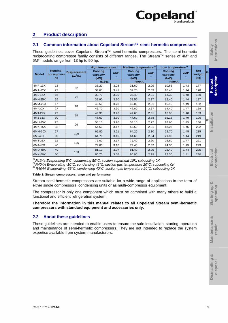
These guidelines cover Copeland Stream™ semi-hermetic compressors. The semi-hermetic reciprocating compressor family consists of different ranges. The Stream™ series of 4M* and 6M* models range from 13 hp to 50 hp.
Cooling
capacity
(kW)
COP
-
Cooling
capacity
(kW)
COP
-
Cooling
capacity
(kW)
COP
-
4MF-13X 13 33.20 3.28 31.60 2.29 10.65 1.43 177
4MA-22X 22 34.60 3.41 32.70 2.39 10.45 1.44 178
4ML-15X 15 39.70 3.30 38.40 2.31 13.30 1.48 180
4MH-25X 25 39.90 3.30 38.50 2.37 12.40 1.44 187
4MM-20X 17 43.50 3.28 42.00 2.31 15.10 1.49 182
4MI-30X 27 43.70 3.30 42.80 2.37 14.40 1.47 188
4MT-22X 22 49.30 3.26 47.60 2.31 16.95 1.48 183
4MJ-33X 30 48.60 3.30 47.60 2.38 16.15 1.49 190
4MU-25X 25 55.10 3.20 53.10 2.27 18.60 1.45 186
4MK-35X 32 54.50 3.17 53.50 2.31 18.25 1.45 202
6MM-30X 27 65.80 3.21 64.20 2.30 22.70 1.45 215
6MI-40X 35 64.70 3.16 64.60 2.34 21.90 1.44 219
6MT-35X 32 73.60 3.17 72.40 2.30 25.60 1.47 221
6MJ-45X 40 72.60 3.16 72.40 2.32 24.30 1.45 223
6MU-40X 40 81.10 3.07 81.40 2.29 28.40 1.44 225
6MK-50X 50 80.70 3.05 80.90 2.29 27.30 1.41 230
Displacement
(m3/h)
Nominal
horsepower
hp
Model
62
381 x 305
71
78
88
99
120
135
153
R404AR134a R404A
Net
weight
(kg)
Footprint
(mm)
Medium temperature2)High temperature1) Low temperature3)
1)
R134a Evaporating 5°C, condensing 50°C, suction superheat 10K, subcooling 0K 2)
R404A Evaporating -10°C, condensing 45°C, suction gas temperature 20°C, subcooling 0K 3)
R404A Evaporating -35°C, condensing 40°C, suction gas temperature 20°C, subcooling 0K
Table 1: Stream compressors range and performance
Stream semi-hermetic compressors are suitable for a wide range of applications in the form of either single compressors, condensing units or as multi-compressor equipment.
The compressor is only one component which must be combined with many others to build a functional and efficient refrigeration system.
Therefore the information in this manual relates to all Copeland Stream semi-hermetic compressors with standard equipment and accessories only.
2.2 About these guidelines
These guidelines are intended to enable users to ensure the safe installation, starting, operation and maintenance of semi-hermetic compressors. They are not intended to replace the system expertise available from system manufacturers.
Safe
ty
instr
ucti
on
s
Pro
du
ct
descri
pti
on
Insta
llati
on
E
lectr
ica
l
co
nn
ecti
on
Sta
rtin
g u
p &
op
era
tio
n
Main
ten
an
ce &
rep
air
Dis
man
tlin
g &
dis
po
sal

4 C6.3.1/0712-1214/E
2.3 Nomenclature
The model designation contains the following technical information about Stream compressors:
2.4 Nameplate information
All important information for identification of the compressor is printed on the nameplate located below the compressor oil pump.
The type of refrigerant used should be stamped on the nameplate by the installer.
Figure 1
The date of production consists of the year and week of production. In addition the year and month of production are shown as part of the serial number (Jan = A, Feb = B, … Dec = L).
2.5 Application range
2.5.1 Qualified refrigerants and oils
IMPORTANT It is essential that the glide of refrigerant blends (primarily R407C) is carefully considered when adjusting pressure and superheat controls.
Oil recharge values can be taken from Copeland™ brand products Select software available at www.emersonclimate.eu.
Qualified refrigerants R404A, R407A, R407C, R407F,
R134a, R22, R507 R22
Copeland brand products standard oils
Emkarate RL 32 3MAF Suniso 3 GS
Servicing oils Emkarate RL 32 3MAF Mobil EAL Arctic 22 CC
Shell 22-12, Suniso 3 GS Fuchs Reniso KM 32, Capella WF 32
Table 2: Qualified refrigerants and oils for recharging and topping up

C6.3.1/0712-1214/E 5
20K Suction Superheat
20oC Suction Gas Return
0oC Suction Gas Return
Envelope area reduction for 4MU*
To recharge:
When the compressor is completely empty of oil, the amount of oil to be “recharged” is typically 0.12 litre less than the original oil charge (oil will already be around the system).
To top up:
During commissioning, planned maintenance or servicing, add oil so that the compressor oil level is correct.
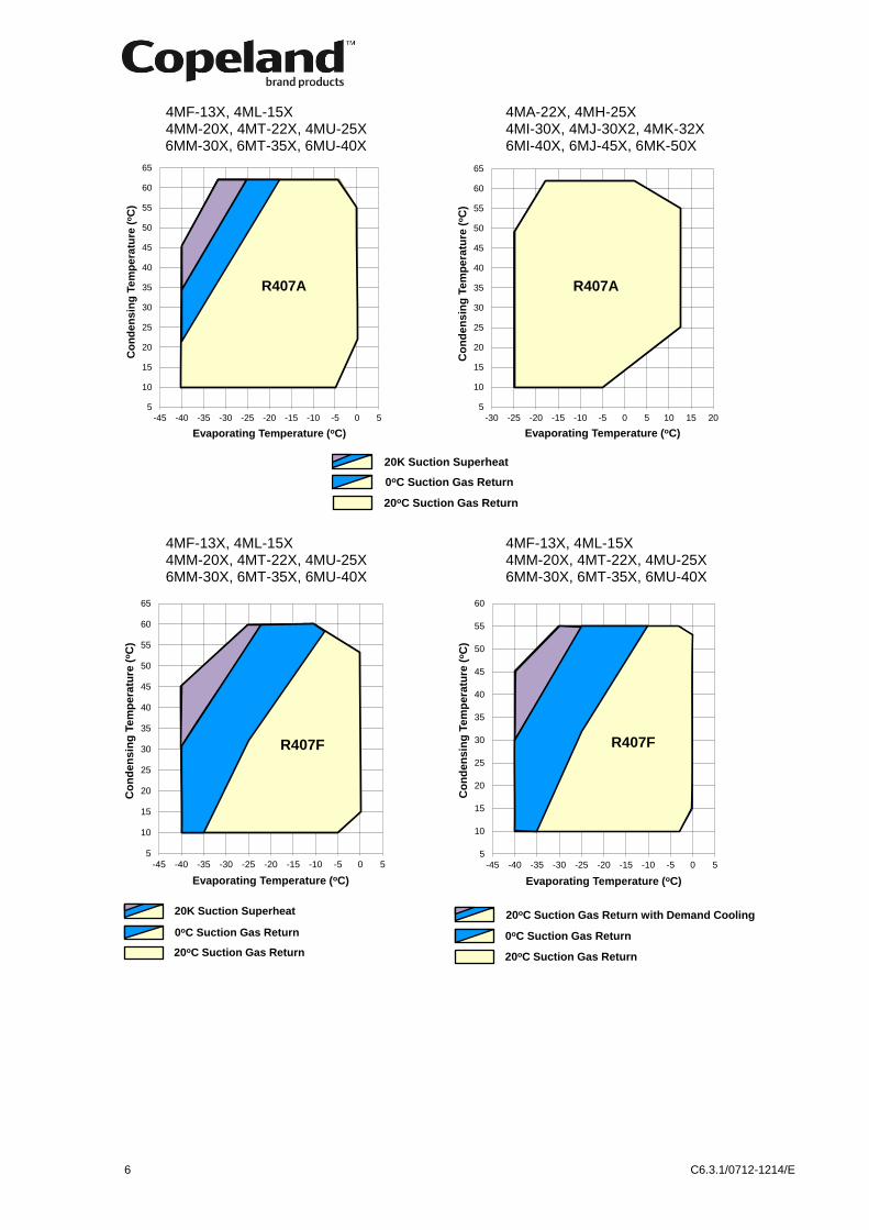
2.5.2 Application limits
4MF-13X, 4ML-15X 4MA-22X1)
, 4MH-25X 4MM-20X, 4MT-22X, 4MU-25X 4MI-30X
2), 4MJ-30X2
2), 4MK-32X
2)
6MM-30X, 6MT-35X, 6MU-40X 6MI-40X, 6MJ-45X, 6MK-50X
Figure 2: Application envelopes for compressors used with R404A and R134a
0
5
10
15
20
25
30
35
40
45
50
55
60
65
-55 -50 -45 -40 -35 -30 -25 -20 -15 -10 -5 0
Co
nd
en
sin
g T
em
pe
ratu
re (
oC
)
Evaporating Temperature (oC)
R404A
5
10
15
20
25
30
35
40
45
50
55
60
65
-50 -45 -40 -35 -30 -25 -20 -15 -10 -5 0 5 10
Co
nd
en
sin
g T
em
pe
ratu
re (
oC
)
Evaporating Temperature (oC)
R404A
5
10
15
20
25
30
35
40
45
50
55
60
65
-25 -20 -15 -10 -5 0 5 10 15
Co
nd
en
sin
g T
em
pe
ratu
re (
oC
)
Evaporating Temperature (oC)
R134a
5
10
15
20
25
30
35
40
45
50
55
60
65
70
75
80
85
-25 -20 -15 -10 -5 0 5 10 15 20 25 30
Co
nd
en
sin
g T
em
pe
ratu
re (
oC
)
Evaporating Temperature (oC)
R134a
25oC Suction Gas Return
20K Suction Superheat
Safe
ty
instr
ucti
on
s
Pro
du
ct
descri
pti
on
Insta
llati
on
E
lectr
ica
l
co
nn
ecti
on
Sta
rtin
g u
p &
op
era
tio
n
Main
ten
an
ce &
rep
air
Dis
man
tlin
g &
dis
po
sal
6 C6.3.1/0712-1214/E
5
10
15
20
25
30
35
40
45
50
55
60
-45 -40 -35 -30 -25 -20 -15 -10 -5 0 5
Co
nd
en
sin
g T
em
pe
ratu
re (
oC
)
Evaporating Temperature (oC)
R407F
20oC Suction Gas Return
0oC Suction Gas Return
20oC Suction Gas Return with Demand Cooling
20oC Suction Gas Return
0oC Suction Gas Return
20K Suction Superheat
5
10
15
20
25
30
35
40
45
50
55
60
65
-30 -25 -20 -15 -10 -5 0 5 10 15 20
Co
nd
en
sin
g T
em
pe
ratu
re (
oC
)
Evaporating Temperature (oC)
R407A
4MF-13X, 4ML-15X 4MA-22X, 4MH-25X 4MM-20X, 4MT-22X, 4MU-25X 4MI-30X, 4MJ-30X2, 4MK-32X 6MM-30X, 6MT-35X, 6MU-40X 6MI-40X, 6MJ-45X, 6MK-50X
4MF-13X, 4ML-15X 4MF-13X, 4ML-15X 4MM-20X, 4MT-22X, 4MU-25X 4MM-20X, 4MT-22X, 4MU-25X 6MM-30X, 6MT-35X, 6MU-40X 6MM-30X, 6MT-35X, 6MU-40X
5
10
15
20
25
30
35
40
45
50
55
60
65
-45 -40 -35 -30 -25 -20 -15 -10 -5 0 5
Co
nd
en
sin
g T
em
pe
ratu
re (
oC
)
Evaporating Temperature (oC)
R407A
5
10
15
20
25
30
35
40
45
50
55
60
65
-45 -40 -35 -30 -25 -20 -15 -10 -5 0 5
Co
nd
en
sin
g T
em
pe
ratu
re (
oC
)
Evaporating Temperature (oC)
R407F
20oC Suction Gas Return
0oC Suction Gas Return
20K Suction Superheat

C6.3.1/0712-1214/E 7
5
10
15
20
25
30
35
40
45
50
55
60
65
-30 -25 -20 -15 -10 -5 0 5 10 15 20
Co
nd
en
sin
g T
em
pe
ratu
re (
oC
)Evaporating Temperature (oC)
R407C
4MA-22X, 4MH-25X 4MA-22X, 4MH-25X 4MI-30X, 4MJ-30X2, 4MK-32X 4MI-30X, 4MJ-30X2, 4MK-32X 6MI-40X, 6MJ-45X, 6MK-50X 6MI-40X, 6MJ-45X, 6MK-50Xà
Figure 3: Application envelopes for compressors used with R407A, R407F and R407C
NOTE: For application envelopes with other refrigerants, please refer to Copeland brand products Select software at www.emersonclimate.eu.
2.6 Design features
2.6.1 Compressor construction
All compressors are fitted with Stream valve plates which cannot be dismantled. To maintain the high capacity of these compressors in case of exchange, the correct valve-plate-to-body gasket must always be selected.
Each cylinder head has 2 plugged 1/8" - 27 NPTF tapped holes for connecting high-pressure switches.
These high-pressure switches must be calibrated and tested before putting the compressor into service. They must stop the compressor if the allowable pressure is exceeded.
The complete cylinder head is under discharge pressure.
Figure 4
2.6.2 Compressor cooling
Compressor motors must always be cooled, and cylinder head cooling may also be needed at certain operating conditions.
All Stream compressors are suction gas-cooled. With suction gas-cooled compressors, the motor is cooled by refrigerant gas that is led over the motor. An additional fan may be required depending upon the operating conditions (see Copeland brand products Select software at www.emersonclimate.eu).
5
10
15
20
25
30
35
40
45
50
55
60
65
-30 -25 -20 -15 -10 -5 0 5 10 15
Co
nd
en
sin
g T
em
pe
ratu
re (
oC
)
Evaporating Temperature (oC)
R407F
20oC Suction Gas Return
0oC Suction Gas Return
20oC Suction Gas Return
Safe
ty
instr
ucti
on
s
Pro
du
ct
descri
pti
on
Insta
llati
on
E
lectr
ica
l
co
nn
ecti
on
Sta
rtin
g u
p &
op
era
tio
n
Main
ten
an
ce &
rep
air
Dis
man
tlin
g &
dis
po
sal

8 C6.3.1/0712-1214/E
2.6.3 Demand cooling
“Demand Cooling” as the term implies means liquid refrigerant injection on demand.
If a low-temperature R22 or R407F installation is required the following compressors can be equipped with a “Demand Cooling” accessory kit:
4MF-13X 4ML-15X 4MM-20X 4MT-22X 4MU-25X
6MM-30X 6MT-35X 6MU-40X
NOTE: R22 is no longer allowed for new refrigeration systems in Europe.
2.6.4 Unloaded start
With direct starting the motor of a compressor is switched directly into the mains by means of a switch. The resulting breakaway starting current amounts to multiple times the rated motor current operating maximum, without consideration being given to transient phenomena.
In the case of high-powered motors the breakaway starting currents become so large that they lead to disruptive voltage dips in the mains. The compressors that are subject to current limitation must therefore by all means be equipped with starting load reduction to guarantee perfect starting even when the voltages amount to less than approximately 85% of the voltage on the nameplate.
2.6.5 Capacity control
For 4M* and 6M* compressors a mechanical capacity control is available. The system used is blocked suction. Be aware that unloaded operation changes the application range of the compressor.
NOTE: For the application range of the compressors with capacity control, refer to Technical Information D7.21.2 “Stream semi-hermetic compressor capacity control”.
2.6.6 Oil pumps
The oil pumps used for Stream compressors are independent of their rotating direction. Stream compressors are delivered with CoreSense™ Diagnostics. The oil pump integrates the electronic switch for integrating oil pressure safety functionality.
2.6.7 Oil pressure
Normal oil pressure is between 1.05 and 4.2 bar higher than crankcase pressure. Net oil pressure can be read by connecting two pressure gauges to the compressor and comparing the readings. One gauge should be connected to the oil pump. The second gauge should be connected to the crankcase (T-fitting instead of plug on the compressor crankcase) or the suction service valve.
During irregular operating conditions, eg, a blockage of the suction filter, the pressure measured at the suction shut-off valve of the compressor may differ widely from that measured at the crankcase. Therefore pressure drops have to be avoided.
2.6.8 Oil circulation
Oil returns with the suction gases through a suction strainer and separates in the motor chamber reaching the crankcase by way of oil return relief valve in the partition between motor housing and crankcase. This relief valve closes on compressor start-up due to the pressure difference arising between motor side and crankcase, thus slowing down pressure decrease in the crankcase over a certain period of time. It reduces the foaming of the oil/refrigerant mixture that would occur if the pressure decreased rapidly. The valve does not reopen until the pressure has been equalized by means of a crankcase ventilating valve. This second valve connects the crankcase and suction side cylinder head. It reduces the pressure difference by means of a very small bore in the plate of the valve so slowly that oil foams less and only limited oil/refrigerant foam is transferred to the oil pump.
Four-cylinder compressors have one crankcase ventilating valve on the left cylinder bank whereas six-cylinder compressors have two ventilating valves on the left and right cylinder banks.

C6.3.1/0712-1214/E 9
2.6.9 Oil level
All compressors are delivered with sufficient oil for normal operation (see Table 2). The optimum oil level should be checked by operating the compressor until the system is stable and then comparing the sight glass reading with the appropriate diagram below. The oil level should be min ¼ and max ¾ of the sight glass.
For service compressors when an oil regulator is used the oil level should be min ¼ and max ¾ of the sight glass. The level can also be checked within 10 seconds of compressor shut-down.
For 4M* and 6M* compressors a higher oil level may be accepted when an oil regulator is in use because the oil separator will reduce excessive oil circulation.
Figure 5: Sight glass reading on 4M* and 6M* compressors
Safe
ty
instr
ucti
on
s
Pro
du
ct
descri
pti
on
Insta
llati
on
E
lectr
ica
l
co
nn
ecti
on
Sta
rtin
g u
p &
op
era
tio
n
Main
ten
an
ce &
rep
air
Dis
man
tlin
g &
dis
po
sal

10 C6.3.1/0712-1214/E
3 Installation
WARNING High pressure! Injury to skin and eyes possible! Be careful when opening connections on a pressurized item.
3.1 Compressor handling
3.1.1 Delivery
Please check whether the delivery is correct and complete. Any deficiency should be reported immediately in writing.
Standard delivery:
Suction and discharge shut-off valves
Oil charge, oil sight glass
Mounting kit
CoreSense™ Diagnostics module
Holding charge up to 2.5 bar(g) (dry air)
3.1.2 Transport and storage
WARNING Risk of collapse! Personal injuries! Move compressors only with appropriate mechanical or handling equipment according to weight. Keep in the upright position. Do not stack pallets on top of each other. Keep the packaging dry at all times.
Figure 6
Compressors are delivered on pallets. Cooling fans are delivered in separate boxes. Accessories may be mounted or delivered loose. Solenoid valves are never mounted.
3.1.3 Positioning and securing
IMPORTANT Handling damage! Compressor malfunction! Only use the lifting eyes whenever the compressor requires positioning. Using discharge or suction connections for lifting may cause damage or leaks.
If possible, the compressor should be kept vertical during handling.
For safety reasons two lifting eyes should be fitted before moving a compressor (½" - 13 UNC). Otherwise refer to drawings on Figure 7 to see how to apply other lifting methods.
4M* 6M* max. 220 kg max. 260 kg
Figure 7
C6.3.1/0712-1214/E 11
In order to avoid refrigerant leaks or other damage the compressors should not be lifted by the service valves or other accessories.
3.1.4 Installation location
Ensure the compressors are installed on a solid level base.
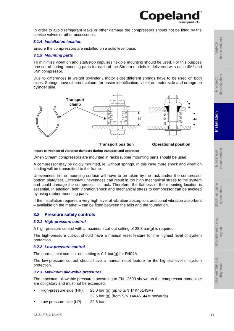
3.1.5 Mounting parts
To minimize vibration and start/stop impulses flexible mounting should be used. For this purpose one set of spring mounting parts for each of the Stream models is delivered with each 4M* and 6M* compressor.
Due to differences in weight (cylinder / motor side) different springs have to be used on both sides. Springs have different colours for easier identification: violet on motor side and orange on cylinder side.
Transport position Operational position
Figure 8: Position of vibration dampers during transport and operation
When Stream compressors are mounted in racks rubber mounting parts should be used.
A compressor may be rigidly mounted, ie, without springs. In this case more shock and vibration loading will be transmitted to the frame.
Unevenness in the mounting surface will have to be taken by the rack and/or the compressor bottom plate/feet. Excessive unevenness can result in too high mechanical stress to the system and could damage the compressor or rack. Therefore, the flatness of the mounting location is essential. In addition, both vibration/shock and mechanical stress to compressor can be avoided by using rubber mounting parts.
If the installation requires a very high level of vibration absorption, additional vibration absorbers – available on the market – can be fitted between the rails and the foundation.
3.2 Pressure safety controls
3.2.1 High-pressure control
A high-pressure control with a maximum cut-out setting of 28.8 bar(g) is required.
The high-pressure cut-out should have a manual reset feature for the highest level of system protection.
3.2.2 Low-pressure control
The normal minimum cut-out setting is 0.1 bar(g) for R404A.
The low-pressure cut-out should have a manual reset feature for the highest level of system protection.
3.2.3 Maximum allowable pressures
The maximum allowable pressures according to EN 12693 shown on the compressor nameplate are obligatory and must not be exceeded.
High-pressure side (HP): 28.0 bar (g) (up to S/N 14K46143M)
32.5 bar (g) (from S/N 14K46144M onwards)
Low-pressure side (LP): 22.5 bar
Safe
ty
instr
ucti
on
s
Pro
du
ct
descri
pti
on
Insta
llati
on
E
lectr
ica
l
co
nn
ecti
on
Sta
rtin
g u
p &
op
era
tio
n
Main
ten
an
ce &
rep
air
Dis
man
tlin
g &
dis
po
sal
Transport
clamp
12 C6.3.1/0712-1214/E
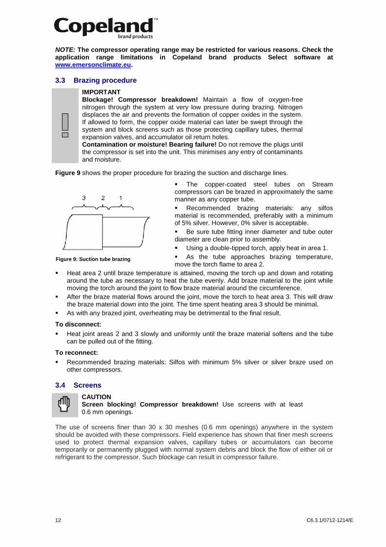
Figure 9: Suction tube brazing
NOTE: The compressor operating range may be restricted for various reasons. Check the application range limitations in Copeland brand products Select software at www.emersonclimate.eu.
3.3 Brazing procedure
IMPORTANT Blockage! Compressor breakdown! Maintain a flow of oxygen-free nitrogen through the system at very low pressure during brazing. Nitrogen displaces the air and prevents the formation of copper oxides in the system. If allowed to form, the copper oxide material can later be swept through the system and block screens such as those protecting capillary tubes, thermal expansion valves, and accumulator oil return holes. Contamination or moisture! Bearing failure! Do not remove the plugs until the compressor is set into the unit. This minimises any entry of contaminants and moisture.
Figure 9 shows the proper procedure for brazing the suction and discharge lines.
The copper-coated steel tubes on Stream compressors can be brazed in approximately the same manner as any copper tube.
Recommended brazing materials: any silfos material is recommended, preferably with a minimum of 5% silver. However, 0% silver is acceptable.
Be sure tube fitting inner diameter and tube outer diameter are clean prior to assembly.
Using a double-tipped torch, apply heat in area 1.
As the tube approaches brazing temperature, move the torch flame to area 2.
Heat area 2 until braze temperature is attained, moving the torch up and down and rotating around the tube as necessary to heat the tube evenly. Add braze material to the joint while moving the torch around the joint to flow braze material around the circumference.
After the braze material flows around the joint, move the torch to heat area 3. This will draw the braze material down into the joint. The time spent heating area 3 should be minimal.
As with any brazed joint, overheating may be detrimental to the final result.
To disconnect:
Heat joint areas 2 and 3 slowly and uniformly until the braze material softens and the tube can be pulled out of the fitting.
To reconnect:
Recommended brazing materials: Silfos with minimum 5% silver or silver braze used on other compressors.
3.4 Screens
CAUTION Screen blocking! Compressor breakdown! Use screens with at least 0.6 mm openings.
The use of screens finer than 30 x 30 meshes (0.6 mm openings) anywhere in the system should be avoided with these compressors. Field experience has shown that finer mesh screens used to protect thermal expansion valves, capillary tubes or accumulators can become temporarily or permanently plugged with normal system debris and block the flow of either oil or refrigerant to the compressor. Such blockage can result in compressor failure.

C6.3.1/0712-1214/E 13
4 Electrical connection
4.1 General recommendations
The compressor terminal box has a wiring diagram on the inside of its cover. Before connecting the compressor, ensure the supply voltage, the phases and the frequency match the nameplate data.
The knockouts have to be removed before the electrical glands can be installed. First make sure that the terminal box is closed with the terminal box cover. We recommend to use a subland twist driller to avoid any damage to the box while removing the knockouts.
Figure 10
4.2 Electrical installation
4.2.1 Three-phase motors
All compressors can be started direct-on-line.
The position of bridges required for direct-on-line start (depending on type of motor and/or mains voltage) is shown in Chapter 4.3 Wiring diagrams.
4.2.2 Star / Delta motors (Y/∆) – Code E
This motor is interchangeable for star (Y) or delta (∆) operation by means of bridges. It is suitable for two voltages, eg, 230V in delta, 400V in star connection. If the supply voltage and the nominal voltage of the motor in ∆-connection are identical, the star connection motor can also be used for starting (remove the bridges!).
4.2.3 Part winding motors (YY/Y) – Code A
Part winding motors contain two separate windings (2/3 + 1/3) which are internally connected in star and operated in parallel. You cannot change the voltage by changing the electrical connections as the motor is only suitable for one voltage.
The first part winding, ie, the 2/3 winding on terminals 1-2-3, can be used for part-winding start (remove the bridges!). After a time delay of 1 ± 0.1 seconds the second part winding, ie, the 1/3 winding on terminals 7-8-9, must be brought on line.
4.3 Wiring diagrams
The position of the jumpers in the terminal box and the recommended wiring diagrams are shown in Figures 11 and 12.
Safe
ty
instr
ucti
on
s
Pro
du
ct
descri
pti
on
Insta
llati
on
E
lectr
ica
l
co
nn
ecti
on
Sta
rtin
g u
p &
op
era
tio
n
Main
ten
an
ce &
rep
air
Dis
man
tlin
g &
dis
po
sal
14 C6.3.1/0712-1214/E
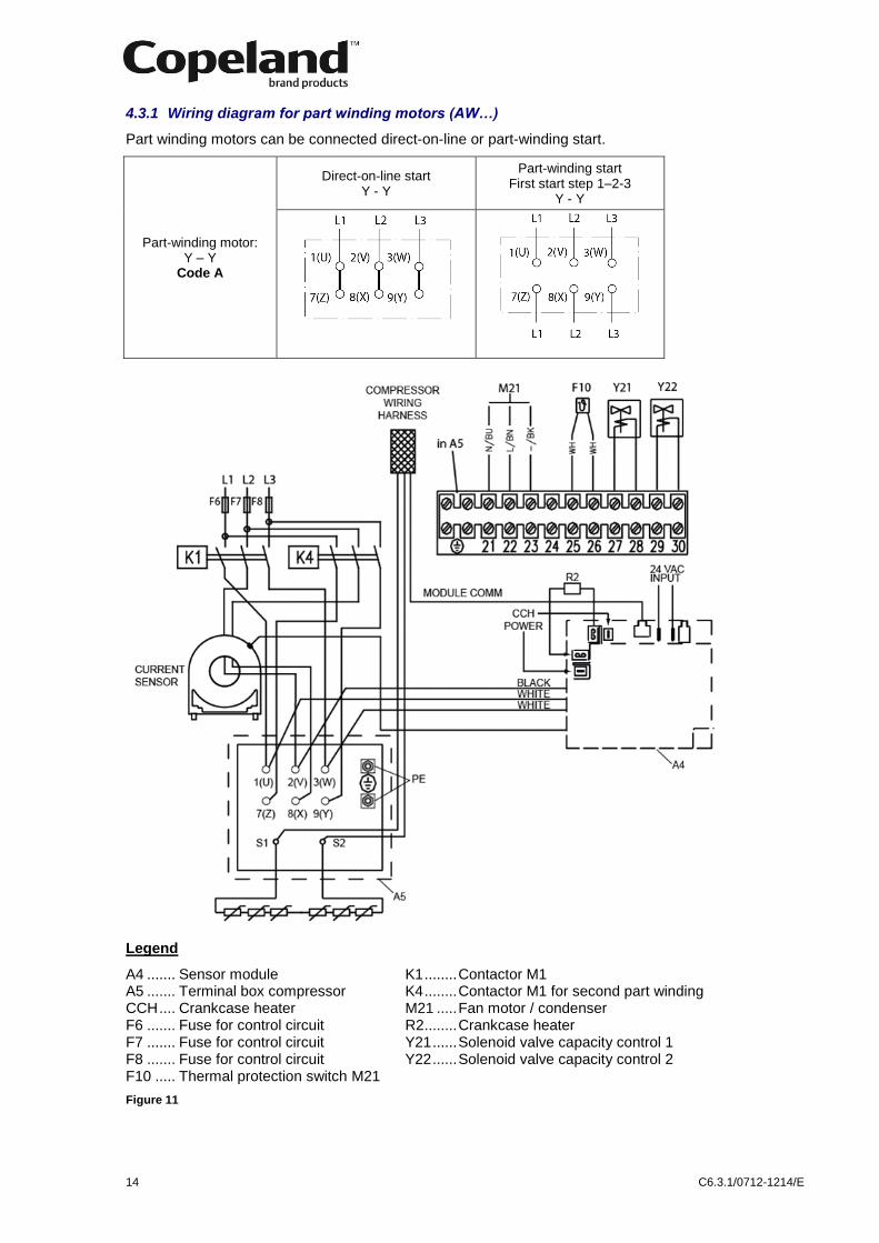
4.3.1 Wiring diagram for part winding motors (AW…)
Part winding motors can be connected direct-on-line or part-winding start.
Part-winding motor: Y – Y
Code A
Direct-on-line start Y - Y
Part-winding start First start step 1–2-3
Y - Y
Legend
A4 ....... Sensor module K1 ........ Contactor M1 A5 ....... Terminal box compressor K4 ........ Contactor M1 for second part winding CCH .... Crankcase heater M21 ..... Fan motor / condenser F6 ....... Fuse for control circuit R2 ........ Crankcase heater F7 ....... Fuse for control circuit Y21 ...... Solenoid valve capacity control 1 F8 ....... Fuse for control circuit Y22 ...... Solenoid valve capacity control 2 F10 ..... Thermal protection switch M21
Figure 11

C6.3.1/0712-1214/E 15
4.3.2 Wiring diagram for Star / Delta motors (EW…)
Star / Delta motors can be connected direct-on-line or Star / Delta start.
Star / Delta
motor
Y - ∆
Code E
Direct-on-line start ∆
Direct-on-line start Y
Star / Delta start Y - ∆
Legend
A4 ....... Sensor module K1 ........ Contactor M1 A5 ....... Terminal box compressor K2 ........ Y - Contactor M1 CCH .... Crankcase heater K3 ........ _ - Contactor M1 F6 ....... Fuse for control circuit M21 ..... Fan motor / condenser F7 ....... Fuse for control circuit R2 ........ Crankcase heater F8 ....... Fuse for control circuit Y21 ...... Solenoid valve capacity control 1 F10 ..... Thermal protection switch M21 Y22 ...... Solenoid valve capacity control 2
Figure 12
Safe
ty
instr
ucti
on
s
Pro
du
ct
descri
pti
on
Insta
llati
on
E
lectr
ica
l
co
nn
ecti
on
Sta
rtin
g u
p &
op
era
tio
n
Main
ten
an
ce &
rep
air
Dis
man
tlin
g &
dis
po
sal

16 C6.3.1/0712-1214/E
4.4 Protection devices
Independently from the internal motor protection, fuses must be installed before the compressor. The selection of fuses has to be carried out according to VDE 0635, DIN 57635, IEC 269-1 or EN 60-269-1.
4.5 CoreSense™ Diagnostics
CoreSense Diagnostics used for all 4M* and 6M* Stream semi-hermetic compressors combines oil and motor protection into one module, replacing OPS1/2 and the electronic module INT69TM. In addition it provides advanced protection such as high discharge temperature, locked rotor, single/missing phase, voltage imbalance and low voltage protection. The module is capable of communication via Modbus® protocol. An external overload protection is not necessary.
Figure 13: CoreSense Diagnostics module
Discharge temperature
Sensor
Oil Pressure Sensor Motor Temperature Sensor (PTC)
CoreSense
Control Module
Current SensorSensor Module

C6.3.1/0712-1214/E 17
For the electrical connection of the CoreSense Diagnostics module, refer to the wiring diagram below:
Figure 14: CoreSense module wiring diagram
NOTE: For more information please refer to Technical Information D7.8.4 “CoreSense™ Diagnostics for Stream refrigeration compressors”.
4.6 Crankcase heaters
IMPORTANT Oil dilution! Bearing malfunction! Turn the crankcase heater on 12 hours before starting the compressor.
A crankcase heater is used to prevent refrigerant from migrating into the shell during standstill periods. Heaters for 4M* and 6M* compressors are screwed into a sleeve (see Figure 15).
The crankcase heater is available in 120V, 230V and 480V.
The operation of 120V and 230V crankcase heaters is controlled by the CoreSense Diagnostics module; this is not possible with 480V heaters.
Figure 15: 100 Watt crankcase heater element
Safe
ty
instr
ucti
on
s
Pro
du
ct
descri
pti
on
Insta
llati
on
E
lectr
ica
l
co
nn
ecti
on
Sta
rtin
g u
p &
op
era
tio
n
Main
ten
an
ce &
rep
air
Dis
man
tlin
g &
dis
po
sal

18 C6.3.1/0712-1214/E
5 Starting up & operation
WARNING Diesel effect! Compressor destruction! The mixture of air and oil at high temperature can lead to an explosion. Avoid operating with air.
5.1 Leak test
The suction shut-off valve and discharge shut-off valve on the compressor must remain closed during pressure testing to prevent air and moisture from entering the compressor. The test pressure (dried nitrogen) must not exceed 20.5 bar provided no other system component’s pressure is lower. In this case the lower pressure is the test pressure.
5.2 System evacuation
Before the installation is put into commission, remove the holding charge then evacuate with a vacuum pump. Proper evacuation reduces residual moisture to 50 ppm. The installation of adequately sized access valves at the furthest point from the compressor in the suction and liquid lines is advisable. To achieve undisturbed operation the compressor valves are closed and the system is evacuated down to 0.3 mbar / 0.225 Torr. Pressure must be measured using a vacuum pressure (Torr) gauge on the access valves and not on the vacuum pump; this serves to avoid incorrect measurements resulting from the pressure gradient along the connecting lines to the pump. Then the compressor must be evacuated.
Due to the factory holding charge of dry air the compressor is under pressure (about 1 to 2.5 bar), this is to indicate that the compressor does not leak.
When removing plugs from the compressor in order to connect a pressure gauge or to fill in oil, the plug may pop out under pressure and oil can spurt out.
5.3 Preliminary checks – Pre-starting
Discuss details of the installation with the installer. If possible, obtain drawings, wiring diagrams, etc. It is ideal to use a check-list but always check the following:
Visual check of the electrics, wiring, fuses etc.
Visual check of the plant for leaks, loose fittings such as TXV bulbs etc.
Compressor oil level
Calibration of HP & LP switches and any pressure actuated valves
Check setting and operation of all safety features and protection devices
All valves in the correct running position
Pressure and compound gauges fitted
Correctly charged with refrigerant
Compressor electrical isolator location & position
5.4 Charging procedure
CAUTION Low suction pressure operation! Compressor Damage! Do not operate with a restricted suction. Do not operate with the low-pressure cut-out bridged.
The system should be liquid-charged through the liquid-receiver shut-off valve or through a valve
in the liquid line. The use of a filter drier in the charging line is highly recommended. The majority
of the charge should be placed in the high side of the system to prevent bearing washout during
first-time start on the assembly line.

C6.3.1/0712-1214/E 19
5.5 Initial start-up
CAUTION Oil dilution! Bearing malfunction! It is important to ensure that new compressors are not subjected to liquid abuse. Turn the crankcase heater on 12 hours before starting the compressor.
CAUTION
High discharge pressure operation! Compressor damage! Do not use compressors to test opening set point of high-pressure cut-out.
The compressor must be equipped according to our technical documentation considering the application intended. Make sure of this before start-up.
For brazing connections where dissimilar or ferric metals are joined a silver alloy rod with a minimum of 30% silver shall be used being either flux coated or with a separate flux.
Bolt torque settings are listed in Appendix 2.
With the exception of rubber-coated metallic gaskets (Wolverine) all gaskets should be oiled before fitting. O-rings should also be oiled.
NOTE: A compressor should never be operated beyond its approved application range!
Check by consulting the appropriate data sheet. To avoid motor damage the compressor
MUST NOT be started, nor may high-potential testing be carried out under vacuum.
5.6 Minimum run time
Emerson Climate Technologies recommends a maximum of 10 starts per hour. The most critical consideration is the minimum run time required to return oil to the compressor after start-up.
5.7 Recommended inverter range
Stream compressors are released for inverter applications from Control Techniques or other brands available on the market.
Over a frequency range the compressor system combination can have frequency bands with higher vibration. The degree of vibration and frequency bands are highly dependent on the system. To help reduce these vibration levels rubber mounting should be used on all inverter driven compressors.
Active oil management should be used for all inverter driven compressors.
Safe
ty
instr
ucti
on
s
Pro
du
ct
descri
pti
on
Insta
llati
on
E
lectr
ica
l
co
nn
ecti
on
Sta
rtin
g u
p &
op
era
tio
n
Main
ten
an
ce &
rep
air
Dis
man
tlin
g &
dis
po
sal

20 C6.3.1/0712-1214/E
6 Maintenance & repair
6.1 Exchanging the refrigerant
Qualified refrigerants and oils are given in Chapter 2.5.1.
It is not necessary to replace the refrigerant with new unless contamination due to an error such as topping up the system with an incorrect refrigerant is suspected. To verify correct refrigerant composition, a sample can be taken for chemical analysis. A check can be made during shut down by comparing the refrigerant temperature and pressure using precision measurements at a location in the system where liquid and vapour phases are present and when the temperatures have stabilised.
In the event that the refrigerant needs replacing, the charge should be recovered using a suitable recovery unit.
In the event that R22 in a system with mineral oil is to be replaced with R407C or R404A, the oil must also be changed.
NOTE: Please refer to Technical Information CC7.26.1 ”Refrigerant Changeover from HCFC to HFC Refrigerants”.
6.2 Replacing a compressor
CAUTION Inadequate lubrication! Bearing destruction! Exchange the accumulator after replacing a compressor with a burned out motor. The accumulator oil return orifice or screen may be plugged with debris or may become plugged. This will result in starvation of oil to the new compressor and a second failure.
In the case of a motor burnout, the majority of contaminated oil will be removed with the
compressor. The rest of the oil is cleaned through the use of suction and liquid line filter driers. A
100% activated alumina suction line filter drier is recommended but must be removed after
72 hours. It is highly recommended that the suction accumulator be replaced if the system
contains one. This is because the accumulator oil-return orifice or screen may be plugged with
debris or may become plugged shortly after a compressor failure. This will result in starvation of
oil to the replacement compressor and a second failure. When a single compressor or tandem is
exchanged in the field, it is possible that a major portion of the oil may still be in the system.
While this may not affect the reliability of the replacement compressor, the extra oil will add to
rotor drag and increase power usage.
6.3 Lubrication and oil removal
CAUTION Chemical reaction! Compressor destruction! Do not mix up ester oils with mineral oil and/or alkyl benzene when used with chlorine-free (HFC) refrigerants.
The compressor is supplied with an initial oil charge. The standard oil charge for use with refrigerants R404A / R407A / R407F / R407C / R134a is a polyolester (POE) lubricant Emkarate RL 32 3MAF. In the field the oil level could be topped up with Mobil EAL Arctic 22 CC if 3MAF is not available. The standard mineral oil for R22 is Suniso 3GS.
One disadvantage of POE is that it is far more hygroscopic than mineral oil (see Figure 16). Only brief exposure to ambient air is needed for POE to absorb sufficient moisture to make it unacceptable for use in a refrigeration system. Since POE holds moisture more readily than mineral oil it is more difficult to remove it through the use of vacuum. Compressors supplied by Emerson Climate Technologies contain oil with low moisture content, and it may rise during the system assembling process. Therefore it is recommended that a properly sized filter-drier is installed in all POE systems. This will maintain the moisture level in the oil to less than 50 ppm. If oil is charged into a system, it is recommended to use POE with moisture content no higher than 50 ppm.

C6.3.1/0712-1214/E 21
The diagram below compares the hygroscopic characteristics of POE oil with mineral oil (moisture absorption in PPM at 25°C and 50% relative humidity).
Figure 16: Absorption of moisture in ester oil in comparison to mineral oil in ppm by weight at 25°C and 50% relative humidity (h=hours)
If the moisture content of the oil in a refrigeration system reaches unacceptably high levels, corrosion and copper plating may occur. The system should be evacuated down to 0.3 mbar or lower. If there is uncertainty as to the moisture content in the system, an oil sample should be taken and tested for moisture. Sight glass/moisture indicators currently available can be used with the HFC refrigerants and lubricants; however, the moisture indicator will just show the moisture content of the refrigerant. The actual moisture level of POE would be higher than the sight glass indicates. This is due to the high hygroscopicity of the POE oil. To determine the actual moisture content of the lubricant, samples have to be taken from the system and analysed.
6.4 Oil additives
Although Emerson Climate Technologies cannot comment on any specific product, from our own testing and past experience, we do not recommend the use of any additives to reduce compressor bearing losses or for any other purpose. Furthermore, the long term chemical stability of any additive in the presence of refrigerant, low and high temperatures, and materials commonly found in refrigeration systems is complex and difficult to evaluate without rigorously controlled chemical laboratory testing. The use of additives without adequate testing may result in malfunction or premature failure of components in the system and, in specific cases, in voiding the warranty on the component.
6.5 Unbrazing system components
WARNING Explosive flame! Burning! Oil-refrigerant mixtures are highly flammable. Remove all refrigerant before opening the system. Avoid working with an unshielded flame in a refrigerant charged system.
Before opening up a system it is important to remove all refrigerant from both the high and low sides of the system. If a brazing torch is then applied to the low side while the low side shell and suction line contain pressure, the pressurized refrigerant and oil mixture could ignite when it escapes and contacts the brazing flame. To prevent this occurrence, it is important to check both the high and low sides with manifold gauges before unbrazing. Instructions should be provided in appropriate product literature and assembly (line repair) areas. If compressor removal is required, the compressor should be cut out of system rather than unbrazed.
7 Dismantling & disposal
Removing oil and refrigerant: Do not disperse in the environment. Use the correct equipment and method of removal. Dispose of oil and refrigerant properly. Dispose of compressor properly.
Safe
ty
instr
ucti
on
s
Pro
du
ct
descri
pti
on
Insta
llati
on
E
lectr
ica
l
co
nn
ecti
on
Sta
rtin
g u
p &
op
era
tio
n
Main
ten
an
ce &
rep
air
Dis
man
tlin
g &
dis
po
sal

22 C6.3.1/0712-1214/E
Appendix 1: Stream compressor connections
4M* 4MF-13X 4ML-15X 4MM-20X 4MT-22X 4MU-25X 4MA-22X 4MH-25X 4MI-30X 4MJ-30X 4MK-32X
SL Suction line size (sweat) 4MF13X, 4ML15X, 4MA22X
Ø 1 5/8" DL Discharge line size (sweat) 4MF13X, 4ML15X, 4MA22X, 4MM20X, 4MH25X, 4MI30X
Ø 1 1/8"
SL
Suction line size (sweat) 4MM20X, 4MH25X, 4MI30X, 4MT22X,4MJ33X, 4MU25X, 4MK35X
Ø 2 1/8" DL Discharge line size (sweat) 4MT22X,4MJ33X, 4MU25X, 4MK35X
Ø 1 3/8"
1 Base mountings Ø 25.5 mm 5 Crankcase heater
2 Magnetic plug 1" - 16 UN 6 Plug oil charge 1/4"
3 Oil sight glass 1/4"-20 UNC 7 Plug high pressure connection 1/8"
4 Plug low pressure connection 1/8"
6M* 6MM-30X, 6MT-35X, 6MU-40X 6MI-40X, 6MJ-45X, 6MK-50X
SL Suction line size (sweat) 6MM30X, 6MT35X, 6MI40X, 6MJ45X
Ø 2 1/8" DL Discharge line size (sweat) 6MT35X, 6MU-40X, 6MJ45X, 6MK-50X
Ø 1 5/8"
SL Suction line size (sweat) 6MK50X, 6MU40X
Ø 2 5/8" DL Discharge line size (sweat) 6MI40X, 6MM30X
Ø 1 3/8"
1 Base mountings Ø 25.5 mm 5 Crankcase heater
2 Magnetic plug 1" - 16 UN 6 Plug oil charge 1/4"
3 Oil sight glass 1/4"-20 UNC 7 Plug high pressure connection 1/8"
4 Plug low pressure connection 1/8"

C6.3.1/0712-1214/E 23
Appendix 2: Tightening torques in Nm
Suction shut-off valve
1/2"-13 UNC Discharge shut-off valve
1/2"-13 UNC
53 - 84 Nm 53 - 84 Nm
SW 19 SW 19
5/8"-11 UNC
Rotalock nut
1 3/4"-12 UNF
104 - 164 Nm 41 - 54 Nm
SW 23.8 SW 50
Bottom plate
3/8"-16 UNC
Mounting foot
3/8"-16 UNC
57 - 68 Nm 57 - 68 Nm
SW 14.2 SW 14.2
Stator cover
1/2"-13 UNC
Housing cover
3/8"-16 UNC
68-79 Nm 57 - 68 Nm
SW 18 SW 14.2
Oil pump
5/16"-18 UNC
Oil sight glass
1/4"-20 UNC
31 - 37 Nm 4.5 - 6 Nm
SW 12.7 SW 11
Oil pressure switch
60 - 75 Nm Magnetic plug
1"-16 UN
102 - 136 Nm
SW 25.4
Terminal stud
10-32 UNF Terminal stud thermistors
10 - 32 UNF
3-4 Nm 3.4 - 4 Nm
SW 9 SW 9
1/4"-28 UNF Mounting plate for terminals
3/8"-16 UNC
5-6.5 Nm 57 - 68 Nm
SW 10 SW 14.2
Cylinder head
1/2"-13 UNC Bolt for connecting rod
1/4"-28 UNF
129-149 Nm 15 - 18 Nm
SW 18 Torx Screws*
Plug 4
1/4"-18 NPTF
27 - 50 Nm
SW 17.5
* In case of replacement of the piston con-rod assemblies, clean the Torx screws and apply Loctite 2701.
The ranges of torque values given in this specification are assembly torque. Torque after joint relaxation must be within 15% of the minimum assembly torque unless re-torque is called for and must not be above 10% of the maximum assembly torque.
Disclaimer
1. The contents of this publication are presented for informational purposes only and are not to be construed as warranties or guarantees, express or implied, regarding the products or services described herein or their use or applicability.
2. Emerson Climate Technologies GmbH and/or its affiliates (collectively "Emerson"), as applicable, reserve the right to modify the design or specifications of such products at any time without notice.
3. Emerson does not assume responsibility for the selection, use or maintenance of any product. Responsibility for proper selection, use and maintenance of any Emerson product remains solely with the purchaser or end user.
4. Emerson does not assume responsibility for possible typographic errors contained in this publication.

Emerson Climate Technologies - European Headquarters - Pascalstrasse 65 - 52076 Aachen, GermanyTel. +49 (0) 2408 929 0 - Fax: +49 (0) 2408 929 570 - Internet: www.emersonclimate.eu
For more details, see www.emersonclimate.eu
C6.3
.1/0
712-
1214
/E
The Emerson Climate Technologies logo is a trademark and service mark of Emerson Electric Co. Emerson Climate Technologies Inc. is a subsidiary of Emerson Electric Co.Copeland is a registered trademark and Copeland Scroll is a trademark of Emerson Climate Technologies Inc.. All other trademarks are property of their respective owners.Emerson Climate Technologies GmbH shall not be liable for errors in the stated capacities, dimensions, etc., as well as typographic errors. Products, specifications, designs and technical data contained in this document are subject to modification by us without prior notice. Illustrations are not binding.© 2014 Emerson Climate Technologies, Inc.
BENELUXDeltakade 7NL-5928 PX VenloTel. +31 77 324 02 34Fax +31 77 324 02 [email protected]
UK & IRELANDUnit 17, Theale Lakes Business ParkUK-Reading, Berkshire RG7 4GB Tel: +44 1189 83 80 00Fax: +44 1189 83 80 [email protected]
BALKANSelska cesta 93HR-10 000 ZagrebTel. +385 1 560 38 75Fax +385 1 560 38 [email protected]
GERMANY, AUSTRIA & SWITZERLANDSenefelder Str. 3D-63477 MaintalTel. +49 6109 605 90Fax +49 6109 60 59 [email protected]
SWEDEN, DENMARK, NORWAY & FINLANDPascalstr. 65D-52076 AachenTel. +49 2408 929 0Fax +49 2408 92 95 [email protected]
FRANCE, GREECE & MAGHREB8, Allée du Moulin Berger
F-69134 Ecully CédexTel.
+33 4 78 66 85 70
Fax
+33 4 78 66 85 [email protected]
EASTERN EUROPE & TURKEYPascalstr. 65D-52076 AachenTel. +49 2408 929 0Fax +49 2408 929 [email protected]
ROMANIA
Tel. +40 374 13 23 50Fax +40 374 13 28 [email protected]
ITALYVia Ramazzotti, 26I-21047 Saronno (VA)Tel. +39 02 96 17 81Fax +39 02 96 17 88 [email protected]
POLANDSzturmowa 2PL-02678 WarsawTel. +48 22 458 92 05Fax +48 22 458 92 [email protected]
MIDDLE EAST & AFRICAPO Box 26382Jebel Ali Free Zone - South, Dubai - UAETel. +971 4 811 81 00Fax +971 4 886 54 [email protected]
SPAIN & PORTUGALC/ LLull, 321 (Edifici CINC)E-08019 BarcelonaTel. +34 93 412 37 52Fax +34 93 412 42 15
RUSSIA & CISLetnikovskaya 10, Bld. 2, floor 5RUS-115114 MoscowTel. +7 495 981 98 11Fax +7 495 981 98 [email protected]
CZECH REPUBLIC Hajkova 2747/22CZ-13000 Prague 3Tel +420 271 035 628Fax +420 271 035 [email protected]
Connect with us: facebook.com/EmersonClimateEurope
UKRAINEKurenevskiy lane, 12, build. A, office 302UA-04073 KievT +38 044 492 99 24 Ext. 232F +38 044 492 99 [email protected]
Technoparc - CS 90220