air-cooled chillers with high speed centrifugal compressors · run test report run test report...
TRANSCRIPT
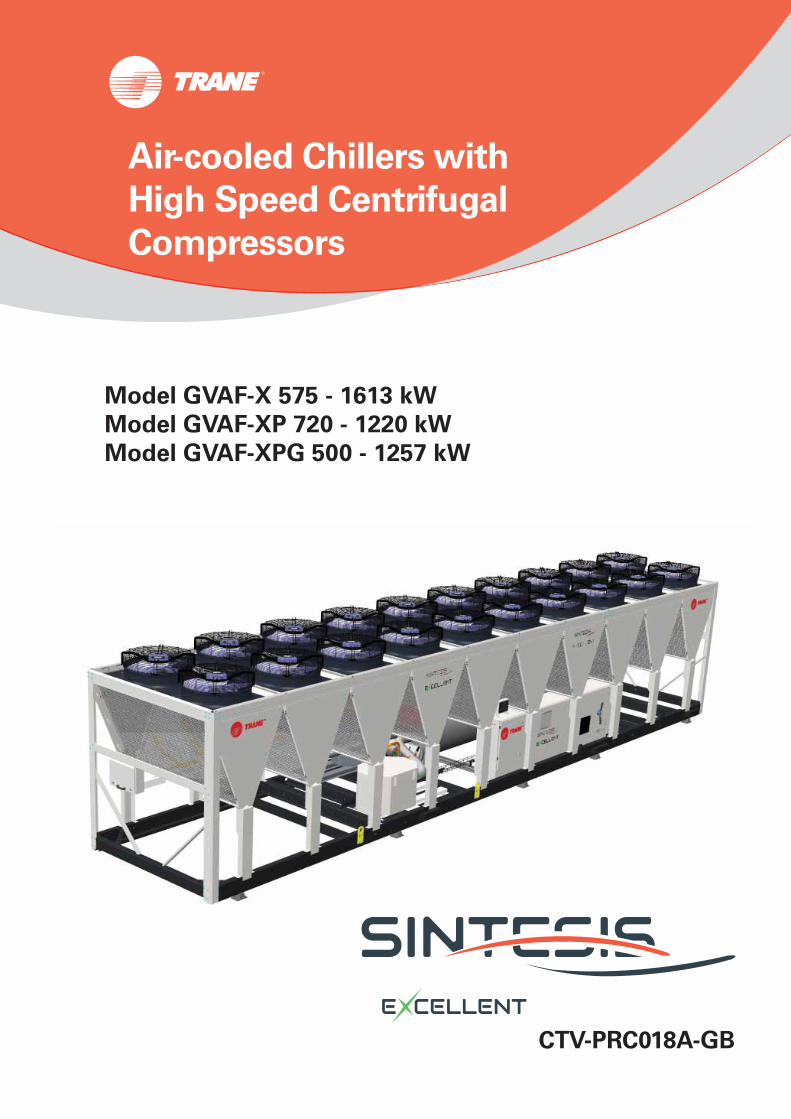
CTV-PRC018A-GB
Air-cooled Chillers with
High Speed Centrifugal
Compressors
Model GVAF-X 575 - 1613 kW
Model GVAF-XP 720 - 1220 kW
Model GVAF-XPG 500 - 1257 kW
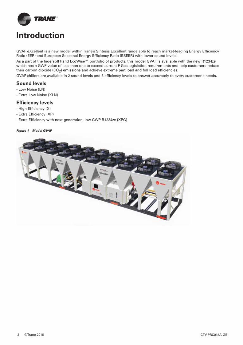
GVAF eXcellent is a new model within Trane’s Sintesis Excellent range able to reach market-leading Energy Effi ciency Ratio (EER) and European Seasonal Energy Effi ciency Ratio (ESEER) with lower sound levels.
As a part of the Ingersoll Rand EcoWise™ portfolio of products, this model GVAF is available with the new R1234ze which has a GWP value of less than one to exceed current F-Gas legislation requirements and help customers reduce their carbon dioxide (CO2) emissions and achieve extreme part load and full load effi ciencies.
GVAF chillers are available in 2 sound levels and 3 effi ciency levels to answer accurately to every customer`s needs.
Sound levels- Low Noise (LN)
- Extra Low Noise (XLN)
Effi ciency levels- High Effi ciency (X)
- Extra Effi ciency (XP)
- Extra Effi ciency with next-generation, low GWP R1234ze (XPG)
Figure 1 – Model GVAF
Introduction
© Trane 2016 CTV-PRC018A-GB2
Introduction .......................................................................................................2
Features and Benefi ts ........................................................................................4
Options ...............................................................................................................5
Application Considerations ..............................................................................8
General Performance Data .............................................................................. 11
General Data ....................................................................................................13
Evaporator Waterside ...................................................................................... 19
Optional Integrated Pump Package ...............................................................20
Hydraulic Module ............................................................................................21
Controls System ..............................................................................................22
TracerTU Interface ....................................................................................................................................23
System Integration ...................................................................................................................................24
Dimensional Data ............................................................................................26
Mechanical Specifi cations ..............................................................................27
Table of Contents
CTV-PRC018A-GB 3
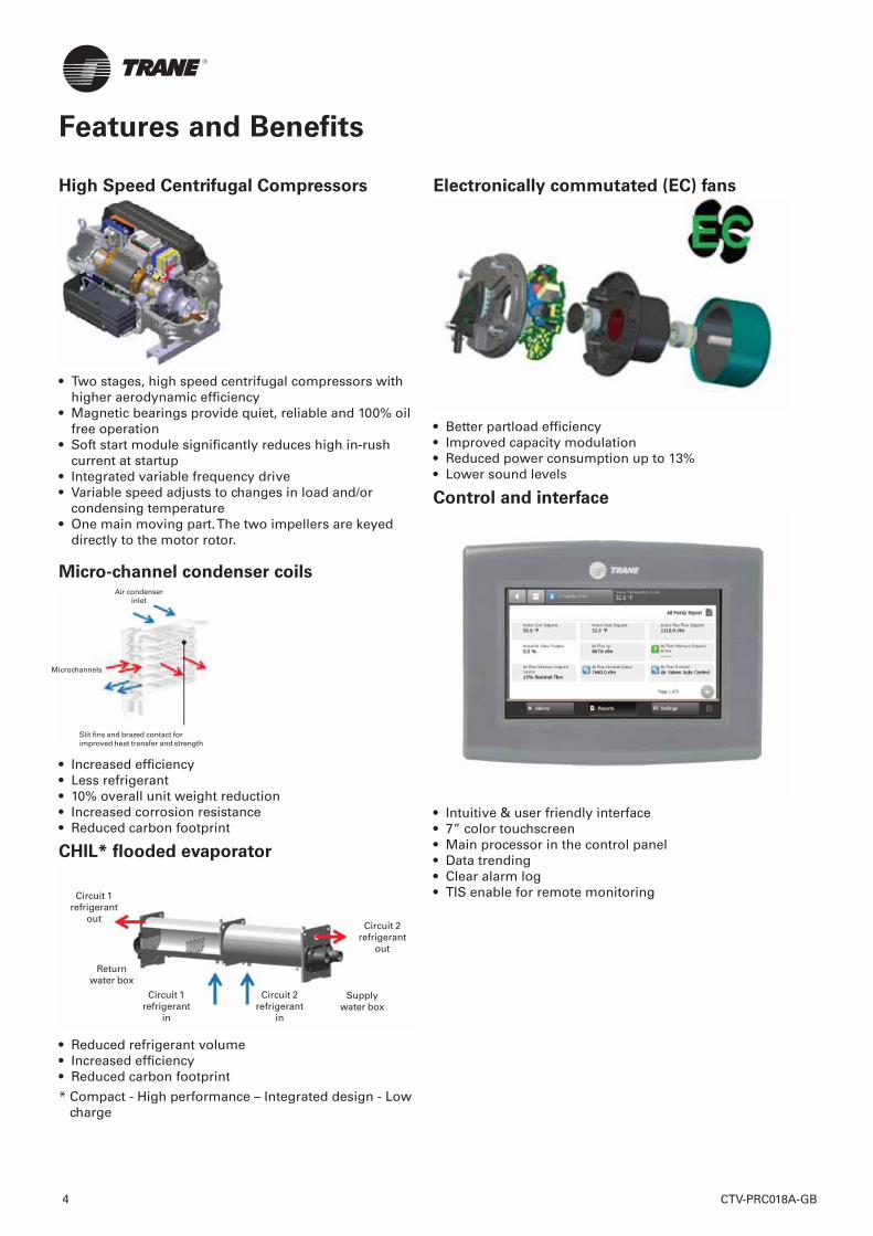
High Speed Centrifugal Compressors
• Two stages, high speed centrifugal compressors with higher aerodynamic effi ciency
• Magnetic bearings provide quiet, reliable and 100% oil free operation
• Soft start module signifi cantly reduces high in-rush current at startup
• Integrated variable frequency drive• Variable speed adjusts to changes in load and/or
condensing temperature• One main moving part. The two impellers are keyed
directly to the motor rotor.
Micro-channel condenser coils
• Increased effi ciency • Less refrigerant• 10% overall unit weight reduction• Increased corrosion resistance• Reduced carbon footprint
CHIL* fl ooded evaporator
• Reduced refrigerant volume• Increased effi ciency• Reduced carbon footprint
* Compact - High performance – Integrated design - Low charge
Electronically commutated (EC) fans
• Better partload effi ciency• Improved capacity modulation• Reduced power consumption up to 13%• Lower sound levels
Control and interface
• Intuitive & user friendly interface• 7” color touchscreen• Main processor in the control panel• Data trending• Clear alarm log• TIS enable for remote monitoring
Features and Benefits
Air condenser inlet
Microchannels
Slit fins and brazed contact for improved heat transfer and strength
Circuit 1 refrigerant
outCircuit 2
refrigerant out
Return water box
Circuit 1 refrigerant
in
Circuit 2 refrigerant
in
Supply water box
CTV-PRC018A-GB4
Options
SmartFlow Control
Constant speed pump – Variable frequency drive
adjustment
The unit is equipped with a pump package driven by a speed inverter, without providing continuous modulation of the speed. The water fl ow is fi xed during commissioning. The goal of this alternative is to provide the appropriate fl ow rate and hydraulic balance, without the need for a mechanical balancing valve, and by taking advantage of the energy consumption optimization of the pump.
Water fl ow is adjusted through parameter 204 of the speed inverter (TR200), when having the dual pump option, the active pump arbitration is based on pump equalization time and pump failure status.
Variable speed pump – Constant differential
pressure (DP)
The unit is equipped with a pump package driven by a speed inverter. The modulation of the pump speed is made in order to ensure that the Differential Pressure (DP) remains constant within the system. The minimum pump speed is factory set at 60% of the nominal speed. The minimum pump frequency can be adjusted through inverter. The constant DP option is intended to be used with 2-way water regulation valves in the customer hydraulic system. At minimum system partial load, when most of the 2-way valves are closed, a minimum fl ow rate must be ensured through the chiller evaporator. DP is measured by a differential pressure sensor supplied by Trane, that the customer must install on the water loop, in a freeze protected area. A regulation valve should be installed on the by-pass line.
Variable speed pump – Constant differential
temperature (DT)
The unit will be equipped with a pump package driven by a speed inverter. The modulation of the pump speed is managed to ensure that chiller DT stays constant. Entering and leaving temperatures at the evaporator will be measured directly by the chiller controller, through the factory-supplied sensor. A DT setpoint will be present on the unit controller. The option for constant DT is intended to be used with 3-way valves on water systems, or 2-way valves on water system but constant fl ow at the by-pass. The minimum pump frequency can be adjusted on the inverter.
Direct and Glycol Free Free-cooling
In order to take advantage of the low ambient temperatures, Sintesis Excellent chillers propose four alternatives of free cooling:
- Total Direct Free-cooling
- Partial Direct Free-cooling
- Total Glycol free Free-cooling
- Partial Glycol free Free-cooling
The advantages of this type of application are:
• A small footprint compared to a system where a dry cooler and a chiller are used
• One single equipment control
• A wide range of capacities
The Sintesis Excellent Series, GVAF Free Cooling are designed for countries that have a signifi cant yearly number of hours below 0 °C and for applications where cooling is needed year round.
Sound level options
Low noise
All GVAF units are equipped with EC fans, compressors are enclosed in a box and discharge line insulated.
Low noise with NNSB
Night noise set back allow to reduce the sound level of the chiller by reducing the speed of EC fans controlled with an external on/off contact.
Extra low noise
Extra low noise units are equipped with NNSB and fan diffusers.
Electrical optionsUnder over voltage protection IP20 internal protection. Flow switch: the fl ow switch is sent as an accessory and has to be installed on site.
Hydraulic module option*Hydraulic module includes the following components: water strainer, expansion vessel 80l, pressure relief valve set at 5 bars, twin pump low head allowing a pressure drop in the water circuit up to 120kPa or twin pump high head allowing a pressure drop in the water circuit up to 220kPa, balancing valve and anti-freeze protection.
CTV-PRC018A-GB 5
CTV-PRC018A-GB6
Options
Control options
BACnet™ communications interface
Allows the user to easily interface with BACnet via a single twisted pair wiring to a factory installed and tested communication board.
LonTalk™ (LCI-C) Communications Interface
Provides the LonMar chiller profi le inputs/outputs for use with a generic building automation system via a single twisted pair wiring to a factory installed and tested communication board.
ModBus™ Communications Interface
Allows the user to easily interface with ModBus via a single twisted pair wiring to a factory installed and tested communication board.
External chilled water setpoint
UC800 accepts either a 2-10 VDC or a 4-20mA input signal, to adjust the chilled water setpoint from a remote location.
External current limit setpoint
UC800 accepts either a 2-10VDC or a 4-20mA input signal to adjust the current limit setpoint from a remote location.
Run test report Run test report gives the results of the performance test of the unit in the design conditions specifi ed in the order write up with water without glycol.
The data recorded are: cooling capacity, power input, air temperature, water entering temperature, water leaving temperature and water fl ow.
* Components may differ depending on unit model and size. Contact your local sales offi ce for details.
Other Options
Relief valvesDual relief valve plus 3 way valve on high pressure side.
High performance insulationEvaporator is insulated with 2 layers of Armafl ex II or equivalent of 19 mm (3/4 inches) thickness and K factor of 0,26 W/m²°K.
Evaporator without insulationEvaporator is not insulated and a specifi c insulation can be done on site.
Coated condensing coilsCondensing coils are protected with a cathodic epoxy electro deposition coating UV resistant.
Neoprene padsNeoprene pads avoid a direct contact of the base of the unit with the ground.
Neoprene isolatorsIsolators provide isolation between chiller and structure to help eliminate vibration transmission and have an effi ciency of 95% minimum.
Grooved pipe plus weld couplingGrooved pipes are connected on water inlet and outlet, the cooling allows the connection between the grooved pipe and the evaporator water connection.
Export shipping packageMetallic clog are fi xed on the base frame of the unit. It prevents direct contact between the chiller and the container while loading and unloading from the container.
CTV-PRC018A-GB 7
Options
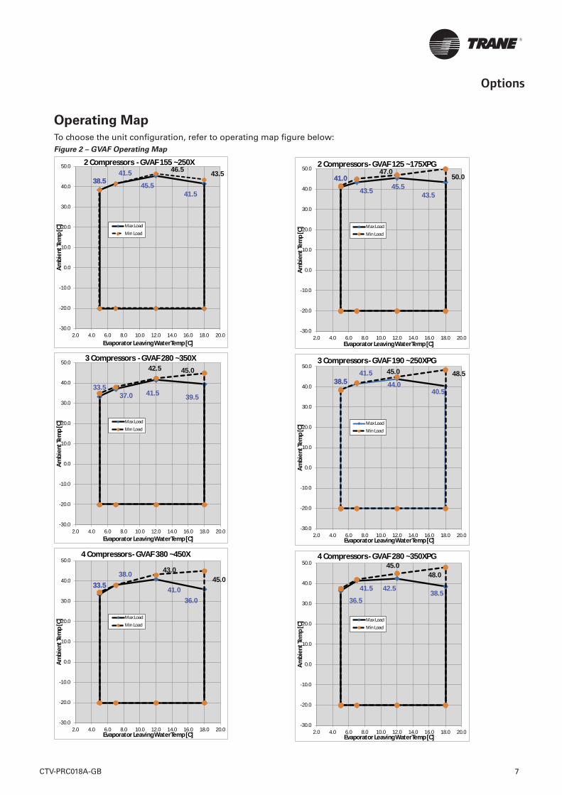
Operating Map
To choose the unit confi guration, refer to operating map fi gure below: Figure 2 – GVAF Operating Map
38.538.541.5
45.541.5
46.5 43.5
-30.0
-20.0
-10.0
0.0
10.0
20.0
30.0
40.0
50.0
2.0 4.0 6.0 8.0 10.0 12.0 14.0 16.0 18.0 20.0
Ambi
ent T
emp
[C]
Evaporator Leaving WaterTemp [C]
2 Compressors - GVAF 155 ~250X
Max Load
Min Load
33.537.0 41.5 39.5
42.5 45.0
-30.0
-20.0
-10.0
0.0
10.0
20.0
30.0
40.0
50.0
2.0 4.0 6.0 8.0 10.0 12.0 14.0 16.0 18.0 20.0
Ambi
ent T
emp
[C]
Evaporator Leaving WaterTemp [C]
3 Compressors - GVAF 280 ~350X
Max Load
Min Load
33.533.538.0
41.036.0
43.045.0
-30.0
-20.0
-10.0
0.0
10.0
20.0
30.0
40.0
50.0
2.0 4.0 6.0 8.0 10.0 12.0 14.0 16.0 18.0 20.0
Ambi
ent T
emp
[C]
Evaporator Leaving WaterTemp [C]
4 Compressors - GVAF 380 ~450X
Max Load
Min Load
41.041.0
43.5 45.543.5
47.050.0
-30.0
-20.0
-10.0
0.0
10.0
20.0
30.0
40.0
50.0
2.0 4.0 6.0 8.0 10.0 12.0 14.0 16.0 18.0 20.0
Ambi
ent T
emp
[C]
Evaporator Leaving WaterTemp [C]
2 Compressors - GVAF 125 ~175XPG
Max Load
Min Load
38.538.541.5
44.040.5
45.0 48.5
-30.0
-20.0
-10.0
0.0
10.0
20.0
30.0
40.0
50.0
2.0 4.0 6.0 8.0 10.0 12.0 14.0 16.0 18.0 20.0
Ambi
ent T
emp
[C]
Evaporator Leaving WaterTemp [C]
3 Compressors - GVAF 190 ~250XPG
Max Load
Min Load
36.5
41.5 42.538.5
45.048.0
-30.0
-20.0
-10.0
0.0
10.0
20.0
30.0
40.0
50.0
2.0 4.0 6.0 8.0 10.0 12.0 14.0 16.0 18.0 20.0
Ambi
ent T
emp
[C]
Evaporator Leaving WaterTemp [C]
4 Compressors - GVAF 280 ~350XPG
Max Load
Min Load
CTV-PRC018A-GB8
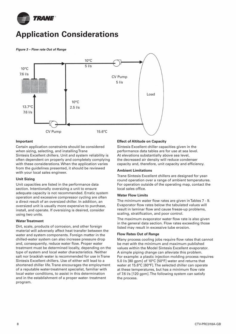
Figure 3 – Flow rate Out of Range
10°C
5 l/s 10°C
7.6 l/sCV Pump
5 l/s
Load
10°C
2.5 l/s13.7°C
7.6 l/s
CV Pump 15.6°C
Important
Certain application constraints should be considered when sizing, selecting, and installing Trane Sintesis Excellent chillers. Unit and system reliability is often dependent on properly and completely complying with these considerations. When the application varies from the guidelines presented, it should be reviewed with your local sales engineer.
Unit Sizing
Unit capacities are listed in the performance data section. Intentionally oversizing a unit to ensure adequate capacity is not recommended. Erratic system operation and excessive compressor cycling are often a direct result of an oversized chiller. In addition, an oversized unit is usually more expensive to purchase, install, and operate. If oversizing is desired, consider using two units.
Water Treatment
Dirt, scale, products of corrosion, and other foreign material will adversely affect heat transfer between the water and system components. Foreign matter in the chilled-water system can also increase pressure drop and, consequently, reduce water fl ow. Proper water treatment must be determined locally, depending on the type of system and local water characteristics. Neither salt nor brackish water is recommended for use in Trane Sintesis Excellent chillers. Use of either will lead to a shortened chiller life. Trane encourages the employment of a reputable water-treatment specialist, familiar with local water conditions, to assist in this determination and in the establishment of a proper water- treatment program.
Effect of Altitude on Capacity
Sintesis Excellent chiller capacities given in the performance data tables are for use at sea level. At elevations substantially above sea level, the decreased air density will reduce condenser capacity and, therefore, unit capacity and effi ciency.
Ambient Limitations
Trane Sintesis Excellent chillers are designed for year-round operation over a range of ambient temperatures. For operation outside of the operating map, contact the local sales offi ce.
Water Flow Limits
The minimum water fl ow rates are given in Tables 7 - 9. Evaporator fl ow rates below the tabulated values will result in laminar fl ow and cause freeze-up problems, scaling, stratifi cation, and poor control.
The maximum evaporator water fl ow rate is also given in the general data section. Flow rates exceeding those listed may result in excessive tube erosion.
Flow Rates Out of Range
Many process cooling jobs require fl ow rates that cannot be met with the minimum and maximum published values within the Model Sintesis Excellent evaporator. A simple piping change can alleviate this problem. For example: a plastic injection molding process requires 5.0 l/s [80 gpm] of 10°C [50°F] water and returns that water at 15.6°C [60°F]. The selected chiller can operate at these temperatures, but has a minimum fl ow rate of 7.6 l/s [120 gpm]. The following system can satisfy the process.
Application Considerations
Flow Control
Trane requires the chilled water fl ow control in conjunction with the Sintesis Excellent Chiller to be done by the chiller.
This will allow the chiller to protect itself in potentially harmful conditions.
Leaving-Water Temperature Limits
The standard leaving solution temperature range is 4.4 to 18°C [40 to 65°F].
Leaving-Water Temperature
Out of Range
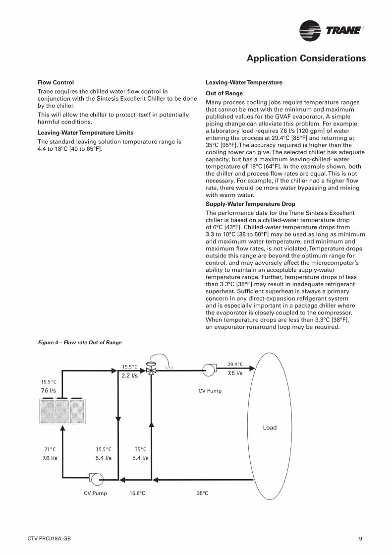
Many process cooling jobs require temperature ranges that cannot be met with the minimum and maximum published values for the GVAF evaporator. A simple piping change can alleviate this problem. For example: a laboratory load requires 7.6 l/s [120 gpm] of water entering the process at 29.4°C [85°F] and returning at 35°C [95°F]. The accuracy required is higher than the cooling tower can give. The selected chiller has adequate capacity, but has a maximum leaving-chilled- water temperature of 18°C [64°F]. In the example shown, both the chiller and process fl ow rates are equal. This is not necessary. For example, if the chiller had a higher fl ow rate, there would be more water bypassing and mixing with warm water.
Supply-Water Temperature Drop
The performance data for the Trane Sintesis Excellent chiller is based on a chilled-water temperature drop of 6°C [43°F]. Chilled-water temperature drops from 3.3 to 10°C [38 to 50°F] may be used as long as minimum and maximum water temperature, and minimum and maximum fl ow rates, is not violated. Temperature drops outside this range are beyond the optimum range for control, and may adversely affect the microcomputer’s ability to maintain an acceptable supply-water temperature range. Further, temperature drops of less than 3.3°C [38°F] may result in inadequate refrigerant superheat. Suffi cient superheat is always a primary concern in any direct-expansion refrigerant system and is especially important in a package chiller where the evaporator is closely coupled to the compressor. When temperature drops are less than 3.3°C [38°F], an evaporator runaround loop may be required.
Application Considerations
Figure 4 – Flow rate Out of Range
15.5°C
2.2 l/s15.5°C
7.6 l/s CV Pump
Load
35°C
5.4 l/s
21°C
7.6 l/s
CV Pump 15.6°C 35°C
29.4°C
7.6 l/s
15.5°C
5.4 l/s
CTV-PRC018A-GB 9
Short Water Loops
The proper location of the temperature control sensor is in the supply (outlet) water connection or pipe. This location allows the building to act as a buffer and assures a slowly-changing return- water temperature. If there is not a suffi cient volume of water in the system to provide an adequate buffer, temperature control can be lost, resulting in erratic system operation and excessive compressor cycling. A short water loop has the same effect as attempting to control using the building return water. Typically, a two-minute water loop is suffi cient to prevent a short water loop. Therefore, as a guideline, ensure that the volume of water in the evaporator loop equals or exceeds two times the evaporator fl ow rate per minute. For a rapidly changing load profi le, the amount of volume should be increased. To prevent the effect of a short water loop, the following item should be given careful consideration: a storage tank or larger header pipe to increase the volume of water in the system and, therefore, reduce the rate of change of the return water temperature.
Application Types
• Comfort cooling
• Industrial process cooling
• Thermal storage
• Low-temperature process cooling.
Application Considerations
CTV-PRC018A-GB10
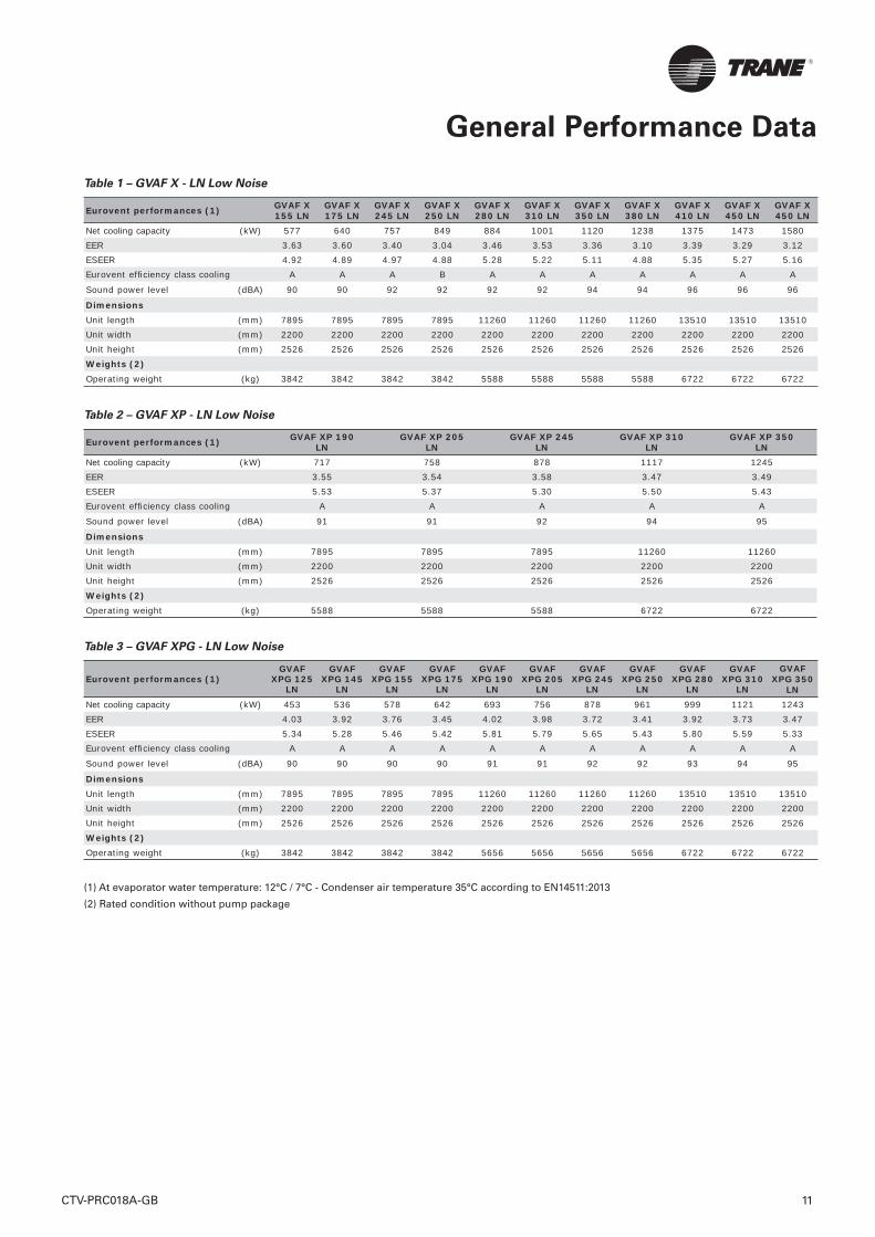
Table 1 – GVAF X - LN Low Noise
Eurovent performances (1) GVAF X 155 LN
GVAF X 175 LN
GVAF X 245 LN
GVAF X 250 LN
GVAF X 280 LN
GVAF X 310 LN
GVAF X 350 LN
GVAF X 380 LN
GVAF X 410 LN
GVAF X 450 LN
GVAF X 450 LN
Net cooling capacity (kW) 577 640 757 849 884 1001 1120 1238 1375 1473 1580EER 3.63 3.60 3.40 3.04 3.46 3.53 3.36 3.10 3.39 3.29 3.12ESEER 4.92 4.89 4.97 4.88 5.28 5.22 5.11 4.88 5.35 5.27 5.16Eurovent effi ciency class cooling A A A B A A A A A A A
Sound power level (dBA) 90 90 92 92 92 92 94 94 96 96 96
DimensionsUnit length (mm) 7895 7895 7895 7895 11260 11260 11260 11260 13510 13510 13510Unit width (mm) 2200 2200 2200 2200 2200 2200 2200 2200 2200 2200 2200Unit height (mm) 2526 2526 2526 2526 2526 2526 2526 2526 2526 2526 2526Weights (2)Operating weight (kg) 3842 3842 3842 3842 5588 5588 5588 5588 6722 6722 6722
Table 2 – GVAF XP - LN Low Noise
Eurovent performances (1) GVAF XP 190LN
GVAF XP 205LN
GVAF XP 245LN
GVAF XP 310LN
GVAF XP 350LN
Net cooling capacity (kW) 717 758 878 1117 1245EER 3.55 3.54 3.58 3.47 3.49ESEER 5.53 5.37 5.30 5.50 5.43Eurovent effi ciency class cooling A A A A A
Sound power level (dBA) 91 91 92 94 95
DimensionsUnit length (mm) 7895 7895 7895 11260 11260Unit width (mm) 2200 2200 2200 2200 2200Unit height (mm) 2526 2526 2526 2526 2526Weights (2)Operating weight (kg) 5588 5588 5588 6722 6722
Table 3 – GVAF XPG - LN Low Noise
Eurovent performances (1)GVAF
XPG 125 LN
GVAF XPG 145
LN
GVAF XPG 155
LN
GVAF XPG 175
LN
GVAF XPG 190
LN
GVAF XPG 205
LN
GVAF XPG 245
LN
GVAF XPG 250
LN
GVAF XPG 280
LN
GVAF XPG 310
LN
GVAF XPG 350
LNNet cooling capacity (kW) 453 536 578 642 693 756 878 961 999 1121 1243EER 4.03 3.92 3.76 3.45 4.02 3.98 3.72 3.41 3.92 3.73 3.47ESEER 5.34 5.28 5.46 5.42 5.81 5.79 5.65 5.43 5.80 5.59 5.33Eurovent effi ciency class cooling A A A A A A A A A A A
Sound power level (dBA) 90 90 90 90 91 91 92 92 93 94 95
DimensionsUnit length (mm) 7895 7895 7895 7895 11260 11260 11260 11260 13510 13510 13510Unit width (mm) 2200 2200 2200 2200 2200 2200 2200 2200 2200 2200 2200Unit height (mm) 2526 2526 2526 2526 2526 2526 2526 2526 2526 2526 2526Weights (2)Operating weight (kg) 3842 3842 3842 3842 5656 5656 5656 5656 6722 6722 6722
(1) At evaporator water temperature: 12°C / 7°C - Condenser air temperature 35°C according to EN14511:2013
(2) Rated condition without pump package
General Performance Data
CTV-PRC018A-GB 11
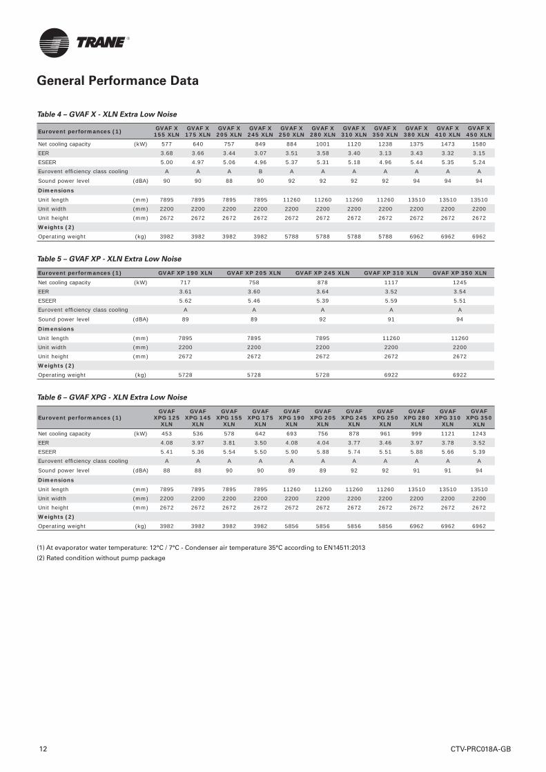
Table 4 – GVAF X - XLN Extra Low Noise
Eurovent performances (1) GVAF X 155 XLN
GVAF X 175 XLN
GVAF X 205 XLN
GVAF X 245 XLN
GVAF X 250 XLN
GVAF X 280 XLN
GVAF X 310 XLN
GVAF X 350 XLN
GVAF X 380 XLN
GVAF X 410 XLN
GVAF X 450 XLN
Net cooling capacity (kW) 577 640 757 849 884 1001 1120 1238 1375 1473 1580EER 3.68 3.66 3.44 3.07 3.51 3.58 3.40 3.13 3.43 3.32 3.15ESEER 5.00 4.97 5.06 4.96 5.37 5.31 5.18 4.96 5.44 5.35 5.24Eurovent effi ciency class cooling A A A B A A A A A A A
Sound power level (dBA) 90 90 88 90 92 92 92 92 94 94 94
DimensionsUnit length (mm) 7895 7895 7895 7895 11260 11260 11260 11260 13510 13510 13510Unit width (mm) 2200 2200 2200 2200 2200 2200 2200 2200 2200 2200 2200Unit height (mm) 2672 2672 2672 2672 2672 2672 2672 2672 2672 2672 2672Weights (2)Operating weight (kg) 3982 3982 3982 3982 5788 5788 5788 5788 6962 6962 6962
Table 5 – GVAF XP - XLN Extra Low Noise
Eurovent performances (1) GVAF XP 190 XLN GVAF XP 205 XLN GVAF XP 245 XLN GVAF XP 310 XLN GVAF XP 350 XLN
Net cooling capacity (kW) 717 758 878 1117 1245EER 3.61 3.60 3.64 3.52 3.54ESEER 5.62 5.46 5.39 5.59 5.51Eurovent effi ciency class cooling A A A A A
Sound power level (dBA) 89 89 92 91 94
DimensionsUnit length (mm) 7895 7895 7895 11260 11260Unit width (mm) 2200 2200 2200 2200 2200Unit height (mm) 2672 2672 2672 2672 2672Weights (2)Operating weight (kg) 5728 5728 5728 6922 6922
Table 6 – GVAF XPG - XLN Extra Low Noise
Eurovent performances (1)GVAF
XPG 125 XLN
GVAF XPG 145
XLN
GVAF XPG 155
XLN
GVAF XPG 175
XLN
GVAF XPG 190
XLN
GVAF XPG 205
XLN
GVAF XPG 245
XLN
GVAF XPG 250
XLN
GVAF XPG 280
XLN
GVAF XPG 310
XLN
GVAF XPG 350
XLNNet cooling capacity (kW) 453 536 578 642 693 756 878 961 999 1121 1243EER 4.08 3.97 3.81 3.50 4.08 4.04 3.77 3.46 3.97 3.78 3.52ESEER 5.41 5.36 5.54 5.50 5.90 5.88 5.74 5.51 5.88 5.66 5.39Eurovent effi ciency class cooling A A A A A A A A A A A
Sound power level (dBA) 88 88 90 90 89 89 92 92 91 91 94
DimensionsUnit length (mm) 7895 7895 7895 7895 11260 11260 11260 11260 13510 13510 13510Unit width (mm) 2200 2200 2200 2200 2200 2200 2200 2200 2200 2200 2200Unit height (mm) 2672 2672 2672 2672 2672 2672 2672 2672 2672 2672 2672Weights (2)Operating weight (kg) 3982 3982 3982 3982 5856 5856 5856 5856 6962 6962 6962
(1) At evaporator water temperature: 12°C / 7°C - Condenser air temperature 35°C according to EN14511:2013
(2) Rated condition without pump package
General Performance Data
CTV-PRC018A-GB12
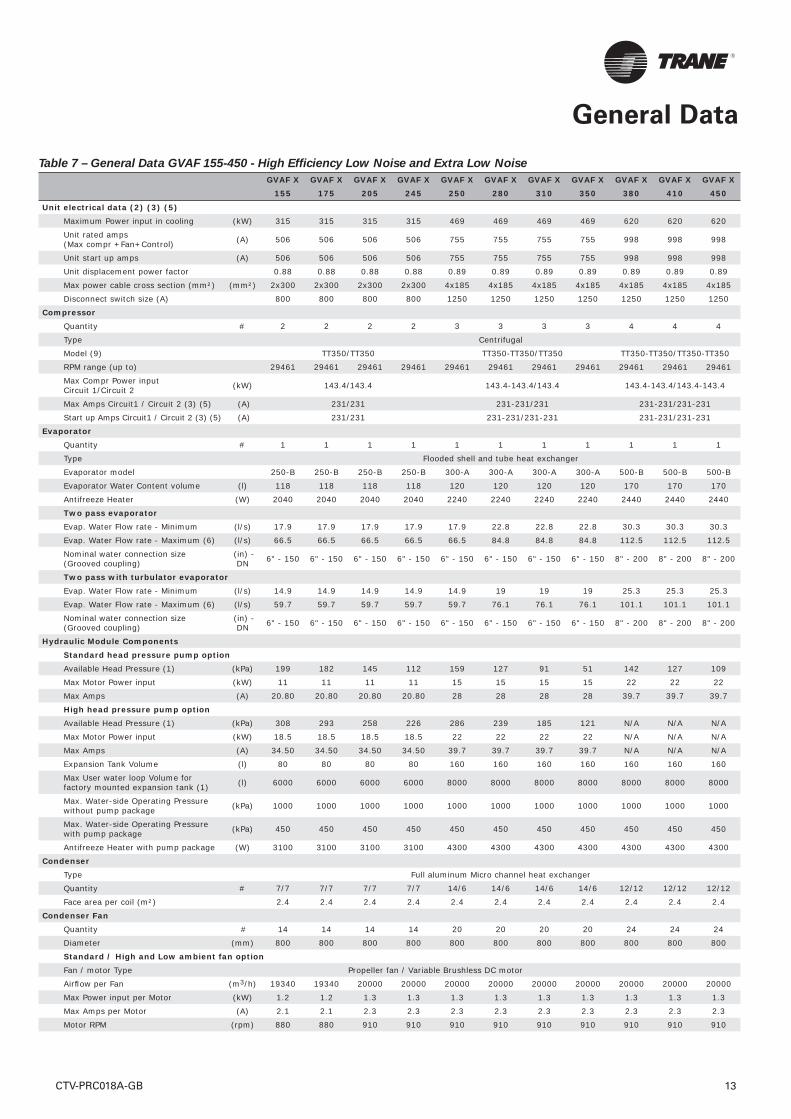
Table 7 – General Data GVAF 155-450 - High Effi ciency Low Noise and Extra Low Noise
GVAF X GVAF X GVAF X GVAF X GVAF X GVAF X GVAF X GVAF X GVAF X GVAF X GVAF X155 175 205 245 250 280 310 350 380 410 450
Unit electrical data (2) (3) (5)Maximum Power input in cooling (kW) 315 315 315 315 469 469 469 469 620 620 620
Unit rated amps (Max compr +Fan+Control) (A) 506 506 506 506 755 755 755 755 998 998 998
Unit start up amps (A) 506 506 506 506 755 755 755 755 998 998 998
Unit displacement power factor 0.88 0.88 0.88 0.88 0.89 0.89 0.89 0.89 0.89 0.89 0.89
Max power cable cross section (mm²) (mm²) 2x300 2x300 2x300 2x300 4x185 4x185 4x185 4x185 4x185 4x185 4x185
Disconnect switch size (A) 800 800 800 800 1250 1250 1250 1250 1250 1250 1250
CompressorQuantity # 2 2 2 2 3 3 3 3 4 4 4
Type Centrifugal
Model (9) TT350/TT350 TT350-TT350/TT350 TT350-TT350/TT350-TT350
RPM range (up to) 29461 29461 29461 29461 29461 29461 29461 29461 29461 29461 29461
Max Compr Power input Circuit 1/Circuit 2 (kW) 143.4/143.4 143.4-143.4/143.4 143.4-143.4/143.4-143.4
Max Amps Circuit1 / Circuit 2 (3) (5) (A) 231/231 231-231/231 231-231/231-231
Start up Amps Circuit1 / Circuit 2 (3) (5) (A) 231/231 231-231/231-231 231-231/231-231
EvaporatorQuantity # 1 1 1 1 1 1 1 1 1 1 1
Type Flooded shell and tube heat exchanger
Evaporator model 250-B 250-B 250-B 250-B 300-A 300-A 300-A 300-A 500-B 500-B 500-B
Evaporator Water Content volume (l) 118 118 118 118 120 120 120 120 170 170 170
Antifreeze Heater (W) 2040 2040 2040 2040 2240 2240 2240 2240 2440 2440 2440
Two pass evaporatorEvap. Water Flow rate - Minimum (l/s) 17.9 17.9 17.9 17.9 17.9 22.8 22.8 22.8 30.3 30.3 30.3
Evap. Water Flow rate - Maximum (6) (l/s) 66.5 66.5 66.5 66.5 66.5 84.8 84.8 84.8 112.5 112.5 112.5
Nominal water connection size (Grooved coupling)
(in) - DN 6" - 150 6" - 150 6" - 150 6" - 150 6" - 150 6" - 150 6" - 150 6" - 150 8" - 200 8" - 200 8" - 200
Two pass with turbulator evaporatorEvap. Water Flow rate - Minimum (l/s) 14.9 14.9 14.9 14.9 14.9 19 19 19 25.3 25.3 25.3
Evap. Water Flow rate - Maximum (6) (l/s) 59.7 59.7 59.7 59.7 59.7 76.1 76.1 76.1 101.1 101.1 101.1
Nominal water connection size (Grooved coupling)
(in) - DN 6" - 150 6" - 150 6" - 150 6" - 150 6" - 150 6" - 150 6" - 150 6" - 150 8" - 200 8" - 200 8" - 200
Hydraulic Module ComponentsStandard head pressure pump optionAvailable Head Pressure (1) (kPa) 199 182 145 112 159 127 91 51 142 127 109
Max Motor Power input (kW) 11 11 11 11 15 15 15 15 22 22 22
Max Amps (A) 20.80 20.80 20.80 20.80 28 28 28 28 39.7 39.7 39.7
High head pressure pump optionAvailable Head Pressure (1) (kPa) 308 293 258 226 286 239 185 121 N/A N/A N/A
Max Motor Power input (kW) 18.5 18.5 18.5 18.5 22 22 22 22 N/A N/A N/A
Max Amps (A) 34.50 34.50 34.50 34.50 39.7 39.7 39.7 39.7 N/A N/A N/A
Expansion Tank Volume (l) 80 80 80 80 160 160 160 160 160 160 160
Max User water loop Volume for factory mounted expansion tank (1) (l) 6000 6000 6000 6000 8000 8000 8000 8000 8000 8000 8000
Max. Water-side Operating Pressure without pump package (kPa) 1000 1000 1000 1000 1000 1000 1000 1000 1000 1000 1000
Max. Water-side Operating Pressure with pump package (kPa) 450 450 450 450 450 450 450 450 450 450 450
Antifreeze Heater with pump package (W) 3100 3100 3100 3100 4300 4300 4300 4300 4300 4300 4300
CondenserType Full aluminum Micro channel heat exchanger
Quantity # 7/7 7/7 7/7 7/7 14/6 14/6 14/6 14/6 12/12 12/12 12/12
Face area per coil (m²) 2.4 2.4 2.4 2.4 2.4 2.4 2.4 2.4 2.4 2.4 2.4
Condenser FanQuantity # 14 14 14 14 20 20 20 20 24 24 24
Diameter (mm) 800 800 800 800 800 800 800 800 800 800 800
Standard / High and Low ambient fan optionFan / motor Type Propeller fan / Variable Brushless DC motor
Airfl ow per Fan (m3/h) 19340 19340 20000 20000 20000 20000 20000 20000 20000 20000 20000
Max Power input per Motor (kW) 1.2 1.2 1.3 1.3 1.3 1.3 1.3 1.3 1.3 1.3 1.3
Max Amps per Motor (A) 2.1 2.1 2.3 2.3 2.3 2.3 2.3 2.3 2.3 2.3 2.3
Motor RPM (rpm) 880 880 910 910 910 910 910 910 910 910 910
General Data
CTV-PRC018A-GB 13
General Data
CTV-PRC018A-GB14
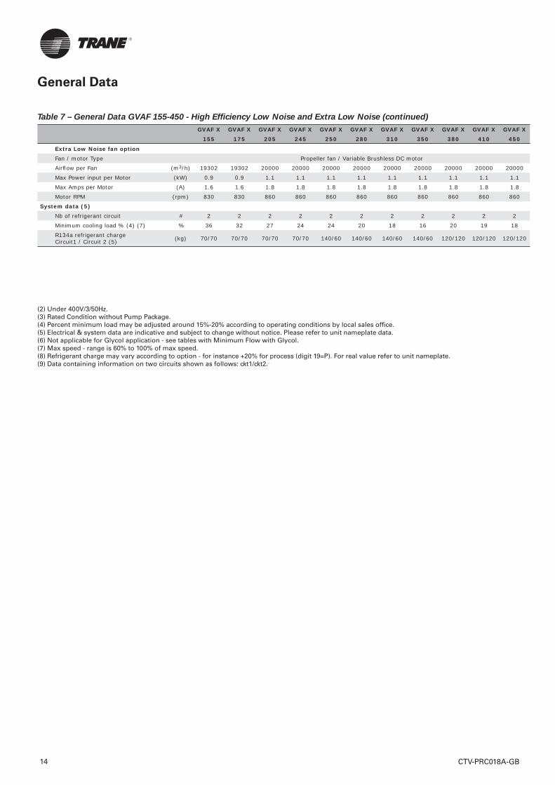
GVAF X GVAF X GVAF X GVAF X GVAF X GVAF X GVAF X GVAF X GVAF X GVAF X GVAF X155 175 205 245 250 280 310 350 380 410 450
Extra Low Noise fan optionFan / motor Type Propeller fan / Variable Brushless DC motor
Airfl ow per Fan (m3/h) 19302 19302 20000 20000 20000 20000 20000 20000 20000 20000 20000
Max Power input per Motor (kW) 0.9 0.9 1.1 1.1 1.1 1.1 1.1 1.1 1.1 1.1 1.1
Max Amps per Motor (A) 1.6 1.6 1.8 1.8 1.8 1.8 1.8 1.8 1.8 1.8 1.8
Motor RPM (rpm) 830 830 860 860 860 860 860 860 860 860 860
System data (5)Nb of refrigerant circuit # 2 2 2 2 2 2 2 2 2 2 2
Minimum cooling load % (4) (7) % 36 32 27 24 24 20 18 16 20 19 18
R134a refrigerant charge Circuit1 / Circuit 2 (5) (kg) 70/70 70/70 70/70 70/70 140/60 140/60 140/60 140/60 120/120 120/120 120/120
(2) Under 400V/3/50Hz.(3) Rated Condition without Pump Package.(4) Percent minimum load may be adjusted around 15%-20% according to operating conditions by local sales offi ce.(5) Electrical & system data are indicative and subject to change without notice. Please refer to unit nameplate data.(6) Not applicable for Glycol application - see tables with Minimum Flow with Glycol.(7) Max speed - range is 60% to 100% of max speed.(8) Refrigerant charge may vary according to option - for instance +20% for process (digit 19=P). For real value refer to unit nameplate. (9) Data containing information on two circuits shown as follows: ckt1/ckt2.
Table 7 – General Data GVAF 155-450 - High Effi ciency Low Noise and Extra Low Noise (continued)

General Data
CTV-PRC018A-GB 15
Table 8 – General Data GVAF 190 - 350 - Extra Effi ciency Low Noise and Extra Low Noise
GVAF XP GVAF XP GVAF XP GVAF XP GVAF XP190 205 245 310 350
Unit electrical data (2) (3) (5)Maximum Power input in cooling (kW) 469 469 469 620 620
Unit rated amps (Max compr +Fan+Control) (A) 764 764 764 998 998
Unit start up amps (A) 764 764 764 998 998
Unit displacement power factor 0.89 0.89 0.89 0.89 0.89
Max power cable cross section (mm²) (mm²) 4x185 4x185 4x185 4x185 4x185
Disconnect switch size (A) 1250 1250 1250 1250 1250
CompressorQuantity # 3 3 3 4 4
Type Centrifugal
Model (9) TT350-TT350/TT350 TT350-TT350/TT350-TT350
RPM range (up to) 29461 29461 29461 29461 29461
Max Compr Power input Circuit 1/Circuit 2 (kW) 143.4-143.4/143.4 143.4-143.4/143.4-143.4
Max Amps Circuit1 / Circuit 2 (3) (5) (A) 231-231/231 231-231/231-231
Start up Amps Circuit1 / Circuit 2 (3) (5) (A) 231-231/231 231-231/231-231
EvaporatorQuantity # 1 1 1 1 1
Type
Evaporator model 300-A 300-A 300-A 500-B 500-B
Evaporator Water Content volume (l) 120 120 120 170 170
Antifreeze Heater (W) 2240 2240 2240 2440 2440
Two pass evaporatorEvap. Water Flow rate - Minimum (l/s) 22.8 22.8 22.8 30.3 30.3
Evap. Water Flow rate - Maximum (6) (l/s) 84.8 84.8 84.8 112.5 112.5
Nominal water connection size (Grooved coupling) (in) - DN 6" - 150 6" - 150 6" - 150 8" - 200 8" - 200
Two pass with turbulator evaporatorEvap. Water Flow rate - Minimum (l/s) 19 19 19 25.3 25.3
Evap. Water Flow rate - Maximum (6) (l/s) 76.1 76.1 76.1 101.1 101.1
Nominal water connection size (Grooved coupling) (in) - DN 6" - 150 6" - 150 6" - 150 8" - 200 8" - 200
Hydraulic Module ComponentsStandard head pressure pump optionAvailable Head Pressure (1) (kPa) 196 188 161 175 160
Max Motor Power input (kW) 15 15 15 22 22
Max Amps (A) 28 28 28 39.7 39.7
High head pressure pump optionAvailable Head Pressure (1) (kPa) 335 324 288 N/A N/A
Max Motor Power input (kW) 22 22 22 N/A N/A
Max Amps (A) 39.7 39.7 39.7 N/A N/A
Expansion Tank Volume (l) 160 160 160 160 160
Max User water loop Volume for factory mounted expansion tank (1) (l) 8000 8000 8000 8000 8000
Max. Water-side Operating Pressure without pump package (kPa) 1000 1000 1000 1000 1000
Max. Water-side Operating Pressure with pump package (kPa) 450 450 450 450 450
Antifreeze Heater with pump package (W) 4300 4300 4300 4300 4300
CondenserType Full aluminum Micro channel heat exchanger
Quantity # 14/6 14/6 14/6 12/12 12/12
Face area per coil (m²) 2.4 2.4 2.4 2.4 2.4
Condenser FanQuantity # 20 20 20 24 24
Diameter (mm) 800 800 800 800 800
Standard / High and Low ambient fan optionFan / motor Type Propeller fan / Variable speed - EC motor
Airfl ow per Fan (m3/h) 20000 20000 20000 20000 20000
Max Power input per Motor (kW) 1.3 1.3 1.3 1.3 1.3
Max Amps per Motor (A) 2.3 2.3 2.3 2.3 2.3
Motor RPM (rpm) 910 910 910 910 910
General Data
Table 8 – General Data GVAF 190 - 350 - Extra Effi ciency Low Noise and Extra Low Noise (continued)
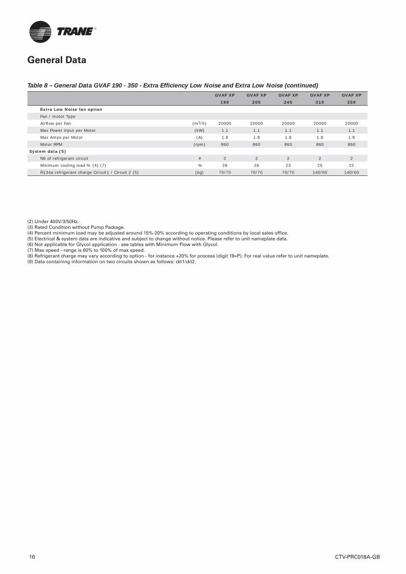
CTV-PRC018A-GB16
GVAF XP GVAF XP GVAF XP GVAF XP GVAF XP190 205 245 310 350
Extra Low Noise fan optionFan / motor Type
Airfl ow per Fan (m3/h) 20000 20000 20000 20000 20000
Max Power input per Motor (kW) 1.1 1.1 1.1 1.1 1.1
Max Amps per Motor (A) 1.8 1.8 1.8 1.8 1.8
Motor RPM (rpm) 860 860 860 860 860
System data (5)Nb of refrigerant circuit # 2 2 2 2 2
Minimum cooling load % (4) (7) % 28 26 23 25 22
R134a refrigerant charge Circuit1 / Circuit 2 (5) (kg) 70/70 70/70 70/70 140/60 140/60
(2) Under 400V/3/50Hz.(3) Rated Condition without Pump Package.(4) Percent minimum load may be adjusted around 15%-20% according to operating conditions by local sales offi ce.(5) Electrical & system data are indicative and subject to change without notice. Please refer to unit nameplate data.(6) Not applicable for Glycol application - see tables with Minimum Flow with Glycol.(7) Max speed - range is 60% to 100% of max speed.(8) Refrigerant charge may vary according to option - for instance +20% for process (digit 19=P). For real value refer to unit nameplate. (9) Data containing information on two circuits shown as follows: ckt1/ckt2.
General Data
CTV-PRC018A-GB 17
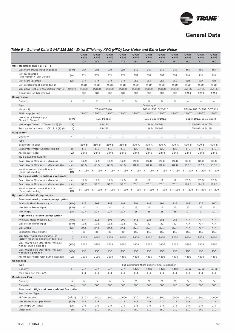
Table 9 – General Data GVAF 125 350 - Extra Effi ciency XPG (HFO) Low Noise and Extra Low Noise
GVAF XP-G
GVAF XP-G
GVAF XP-G
GVAF XP-G
GVAF XP-G
GVAF XP-G
GVAF XP-G
GVAF XP-G
GVAF XP-G
GVAF XP-G
GVAF XP-G
125 145 155 175 190 205 245 250 280 310 350
Unit electrical data (2) (3) (5)Maximum Power input in cooling (kW) 234 234 234 234 347 347 347 347 457 457 457
Unit rated amps (Max compr +Fan+Control) (A) 374 374 374 374 557 557 557 557 734 734 734
Unit start up amps (A) 374 374 374 374 557 557 557 557 734 734 734
Unit displacement power factor 0.88 0.88 0.88 0.88 0.89 0.89 0.89 0.89 0.89 0.89 0.89
Max power cable cross section (mm²) (mm²) 2x300 2x300 2x300 2x300 2x300 2x300 2x300 2x300 4x185 4x185 4x185
Disconnect switch size (A) 630 630 630 630 800 800 800 800 1250 1250 1250
CompressorQuantity # 2 2 2 2 3 3 3 3 4 4 4
Type Centrifugal
Model (9) TG310/TG310 TG310-TG310/TG310 TG310-TG310/TG310-TG310
RPM range (up to) 27957 27957 27957 27957 27957 27957 27957 27957 27957 27957 27957
Max Compr Power input Circuit 1/Circuit 2 (kW) 101.3/101.3 101.3-101.3/101.3 101.3-101.3/101.3-101.3
Max Amps Circuit1 / Circuit 2 (3) (5) (A) 165-165 165-165/165 165-165/165-165
Start up Amps Circuit1 / Circuit 2 (3) (5) (A) 165-165 165-165/165 165-165/165-165
EvaporatorQuantity # 1 1 1 1 1 1 1 1 1 1 1
Type
Evaporator model 250-B 250-B 250-B 250-B 300-A 300-A 300-A 300-A 500-B 500-B 500-B
Evaporator Water Content volume (l) 118 118 118 118 120 120 120 120 170 170 170
Antifreeze Heater (W) 2040 2040 2040 2040 2240 2240 2240 2240 2440 2440 2440
Two pass evaporatorEvap. Water Flow rate - Minimum (l/s) 17.9 17.9 17.9 17.9 22.8 22.8 22.8 22.8 30.3 30.3 30.3
Evap. Water Flow rate - Maximum (6) (l/s) 66.5 66.5 66.5 66.5 84.8 84.8 84.8 84.8 112.5 112.5 112.5
Nominal water connection size (Grooved coupling)
(in) - DN 6" - 150 6" - 150 6" - 150 6" - 150 6" - 150 6" - 150 6" - 150 6" - 150 8" - 200 8" - 200 8" - 200
Two pass with turbulator evaporatorEvap. Water Flow rate - Minimum (l/s) 14.9 14.9 14.9 14.9 19 19 19 19 25.3 25.3 25.3
Evap. Water Flow rate - Maximum (6) (l/s) 59.7 59.7 59.7 59.7 76.1 76.1 76.1 76.1 101.1 101.1 101.1
Nominal water connection size (Grooved coupling)
(in) - DN 6" - 150 6" - 150 6" - 150 6" - 150 6" - 150 6" - 150 6" - 150 6" - 150 8" - 200 8" - 200 8" - 200
Hydraulic Module ComponentsStandard head pressure pump optionAvailable Head Pressure (1) (kPa) 225 208 198 181 201 188 161 139 188 175 160
Max Motor Power input (kW) 11 11 11 11 15 15 15 15 22 22 22
Max Amps (A) 20.8 20.8 20.8 20.8 28 28 28 28 39.7 39.7 39.7
High head pressure pump optionAvailable Head Pressure (1) (kPa) 334 318 308 292 341 325 288 256 N/A N/A N/A
Max Motor Power input (kW) 18.5 18.5 18.5 18.5 22 22 22 22 N/A N/A N/A
Max Amps (A) 34.5 34.5 34.5 34.5 39.7 39.7 39.7 39.7 N/A N/A N/A
Expansion Tank Volume (l) 80 80 80 80 160 160 160 160 160 160 160
Max User water loop Volume for factory mounted expansion tank (1) (l) 6000 6000 6000 6000 8000 8000 8000 8000 8000 8000 8000
Max. Water-side Operating Pressure without pump package (kPa) 1000 1000 1000 1000 1000 1000 1000 1000 1000 1000 1000
Max. Water-side Operating Pressure with pump package (kPa) 450 450 450 450 450 450 450 450 450 450 450
Antifreeze Heater with pump package (W) 3100 3100 3100 4300 4300 4300 4300 4300 4300 4300 4300
CondenserType Full aluminum Micro channel heat exchanger
Quantity # 7/7 7/7 7/7 7/7 14/6 14/6 14/6 14/6 12/12 12/12 12/12
Face area per coil (m²) 2.4 2.4 2.4 2.4 2.4 2.4 2.4 2.4 2.4 2.4 2.4
Condenser FanQuantity # 14 14 14 14 20 20 20 20 24 24 24
Diameter (mm) 800 800 800 800 800 800 800 800 800 800 800
Standard / High and Low ambient fan optionFan / motor Type
Airfl ow per Fan (m3/h) 16703 17802 18901 20000 16703 17802 18901 20000 17802 18901 20000
Max Power input per Motor (kW) 0.8 0.9 1.1 1.3 0.8 0.9 1.1 1.3 0.9 1.1 1.3
Max Amps per Motor (A) 1.3 1.6 1.9 2.3 1.3 1.6 1.9 2.3 1.6 1.9 2.3
Motor RPM (rpm) 760 810 860 910 760 810 860 910 810 860 910
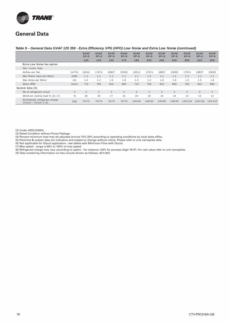
General Data
Table 9 – General Data GVAF 125 350 - Extra Effi ciency XPG (HFO) Low Noise and Extra Low Noise (continued)
CTV-PRC018A-GB18
GVAF XP-G
GVAF XP-G
GVAF XP-G
GVAF XP-G
GVAF XP-G
GVAF XP-G
GVAF XP-G
GVAF XP-G
GVAF XP-G
GVAF XP-G
GVAF XP-G
125 145 155 175 190 205 245 250 280 310 350
Extra Low Noise fan optionFan / motor Type
Airfl ow per Fan (m3/h) 16512 17674 18837 20000 16512 17674 18837 20000 17674 18837 20000
Max Power input per Motor (kW) 1.1 1.1 1.1 1.1 1.1 1.1 1.1 1.1 1.1 1.1 1.1
Max Amps per Motor (A) 1.0 1.2 1.5 1.8 1.0 1.2 1.8 1.8 1.2 1.5 1.8
Motor RPM (rpm) 710 760 810 860 710 760 810 860 760 810 860
System data (5)Nb of refrigerant circuit # 2 2 2 2 2 2 2 2 2 2 2
Minimum cooling load % (4) (7) % 34 29 27 24 20 18 16 16 14 13 12
R1234ze(E) refrigerant charge Circuit1 / Circuit 2 (5) (kg) 70/70 70/70 70/70 70/70 140/60 140/60 140/60 140/60 120/120 120/120 120/120
(2) Under 400V/3/50Hz.(3) Rated Condition without Pump Package.(4) Percent minimum load may be adjusted around 15%-20% according to operating conditions by local sales offi ce.(5) Electrical & system data are indicative and subject to change without notice. Please refer to unit nameplate data.(6) Not applicable for Glycol application - see tables with Minimum Flow with Glycol.(7) Max speed - range is 60% to 100% of max speed.(8) Refrigerant charge may vary according to option - for instance +20% for process (digit 19=P). For real value refer to unit nameplate. (9) Data containing information on two circuits shown as follows: ckt1/ckt2.
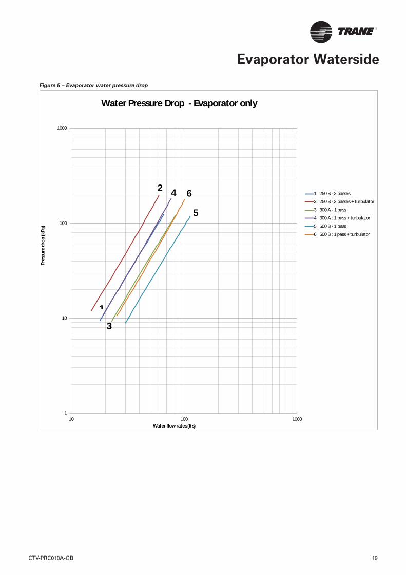
Evaporator Waterside
CTV-PRC018A-GB 19
Figure 5 – Evaporator water pressure drop
1
10
100
1000
10 100 1000
Pres
sure
dro
p (k
Pa)
Water flow rates (l/s)
1. 250 B - 2 passes
2. 250 B - 2 passes + turbulator
3. 300 A - 1 pass
4. 300 A : 1 pass + turbulator
5. 500 B - 1 pass
6. 500 B : 1 pass + turbulator
1
2
3
4
5
6
Water Pressure Drop - Evaporator only
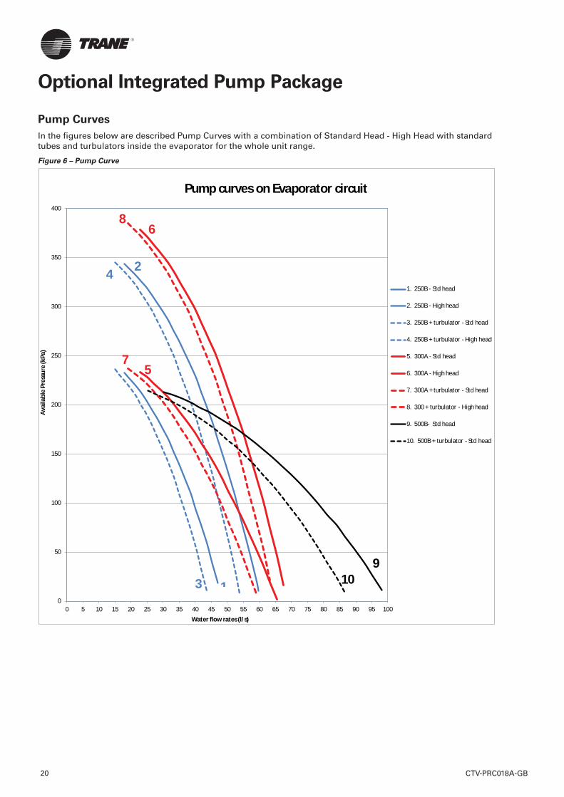
Optional Integrated Pump Package
Pump Curves
In the fi gures below are described Pump Curves with a combination of Standard Head - High Head with standard tubes and turbulators inside the evaporator for the whole unit range.
Figure 6 – Pump Curve
0
50
100
150
200
250
300
350
400
0 5 10 15 20 25 30 35 40 45 50 55 60 65 70 75 80 85 90 95 100
Avai
labl
e Pr
essu
re (k
Pa)
Water flow rates (l/s)
1. 250B - Std head
2. 250B - High head
3. 250B + turbulator - Std head
4. 250B + turbulator - High head
5. 300A - Std head
6. 300A - High head
7. 300A + turbulator - Std head
8. 300 + turbulator - High head
9. 500B- Std head
10. 500B + turbulator - Std head
1
2
3
4
57
6
9
Pump curves on Evaporator circuit
8
10
CTV-PRC018A-GB20
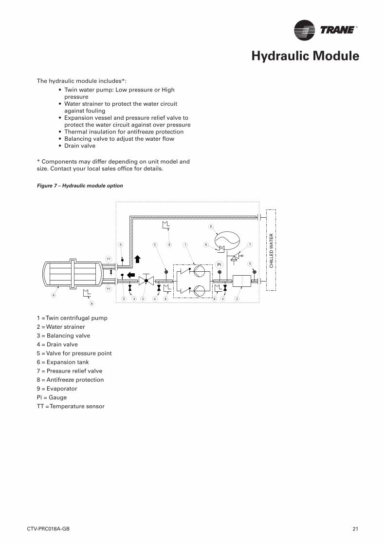
The hydraulic module includes*:
• Twin water pump: Low pressure or High pressure
• Water strainer to protect the water circuit against fouling
• Expansion vessel and pressure relief valve to protect the water circuit against over pressure
• Thermal insulation for antifreeze protection• Balancing valve to adjust the water fl ow• Drain valve
* Components may differ depending on unit model and size. Contact your local sales offi ce for details.
Figure 7 – Hydraulic module option
1 = Twin centrifugal pump
2 = Water strainer
3 = Balancing valve
4 = Drain valve
5 = Valve for pressure point
6 = Expansion tank
7 = Pressure relief valve
8 = Antifreeze protection
9 = Evaporator
Pi = Gauge
TT = Temperature sensor
Hydraulic Module
CH
ILLE
D W
ATE
R
5Pi
1
23 4 4
5
6
7
9
TT
TT
8
88
8
845
5
CTV-PRC018A-GB 21
Controls System
Tracer UC800 Controller
Today’s Sintesis Excellent chillers offer predictive controls that anticipate and compensate for load changes. Other control strategies made possible with the Tracer UC800 controls are:
Feedforward Adaptive Control
Feedforward is an open-loop, predictive control strategy designed to anticipate and compensate for load changes. It uses evaporator entering-water temperature as an indication of load change.
This allows the controller to respond faster and maintain stable leaving-water temperatures.
Soft Loading
The chiller controller uses soft loading except during manual operation. Large adjustments due to load or setpoint changes are made gradually, preventing the compressor from cycling unnecessarily. It does this by internally fi ltering the setpoints to avoid reaching the differential-to-stop or the demand limit. Soft loading applies to the leaving chilled-water temperature and demand limit setpoints.
Adaptive Controls
There are many objectives that the controller must meet, but it cannot satisfy more than one objective at a time. Typically, the controllers primary objective is to maintain the evaporator leaving water temperature.
Whenever the controller senses that it can no longer meet its primary objective without triggering a protective shutdown, it focuses on the most critical secondary objective. When the secondary objective is no longer critical, the controller reverts to its primary objective
Rapid Restart
The controller allows the Sintesis Excellent chiller to perform a Rapid Restart. A Rapid Restart is performed after a momentary power loss if it occurs during operation. Similarly, if the chiller shuts down on a non-latching diagnostic and the diagnostic later clears itself, a Rapid Restart will be initiated
AdaptiSpeed Control
The speed control is now optimized mathematically and controlled simultaneously. The increased performance of the UC800 Controller allows the chiller to operate longer at higher effi ciency, and with greater stability.
Variable-Primary Flow (VPF)
Chilled-water systems that vary the water fl ow through chiller evaporators have caught the attention of engineers, contractors, building owners, and operators. Varying the water fl ow reduces the energy consumed by pumps, while having limited effect on the chiller energy consumption. This strategy can be a signifi cant source of energy savings, depending on the application.
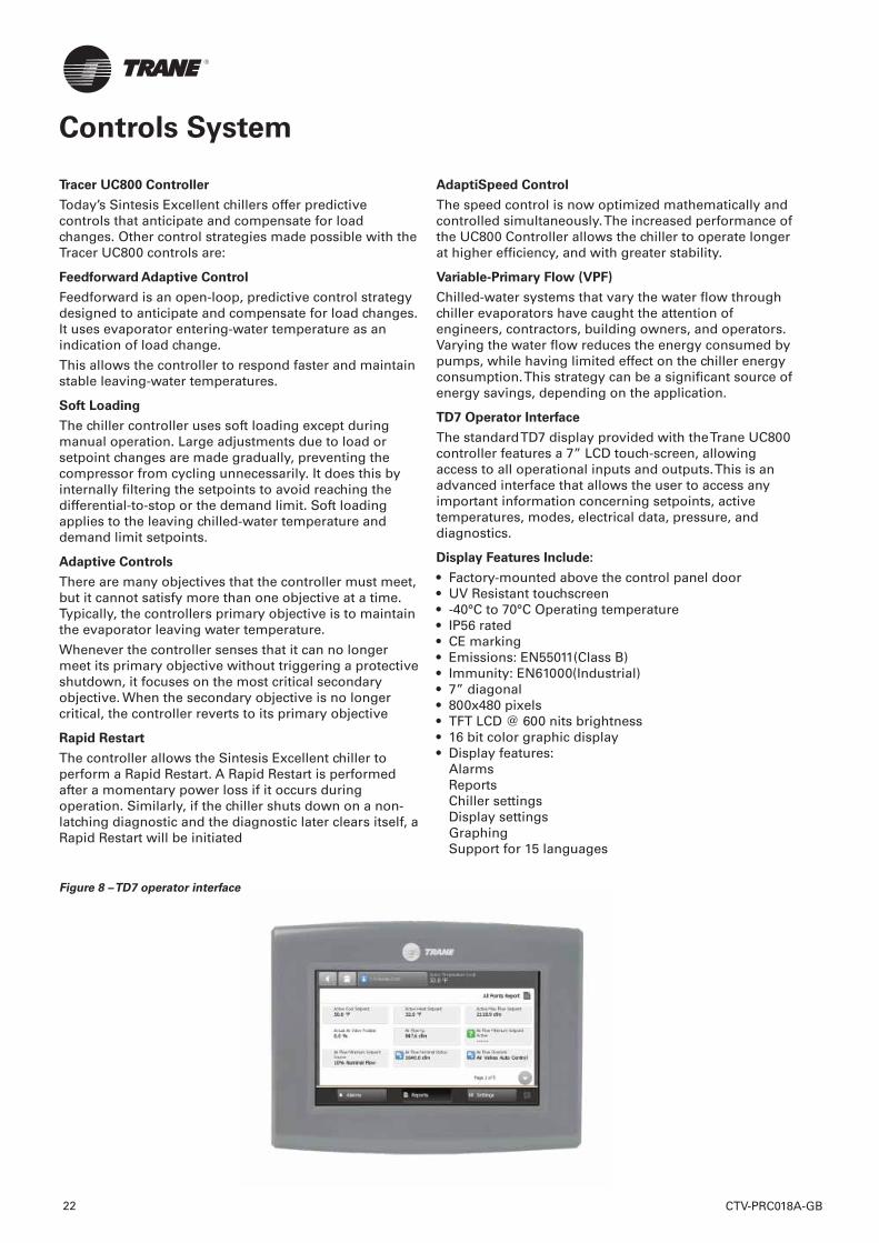
TD7 Operator Interface
The standard TD7 display provided with the Trane UC800 controller features a 7” LCD touch-screen, allowing access to all operational inputs and outputs. This is an advanced interface that allows the user to access any important information concerning setpoints, active temperatures, modes, electrical data, pressure, and diagnostics.
Display Features Include:
• Factory-mounted above the control panel door• UV Resistant touchscreen• -40°C to 70°C Operating temperature• IP56 rated • CE marking• Emissions: EN55011(Class B)• Immunity: EN61000(Industrial)• 7” diagonal• 800x480 pixels• TFT LCD @ 600 nits brightness• 16 bit color graphic display• Display features:
AlarmsReportsChiller settingsDisplay settingsGraphingSupport for 15 languages
Figure 8 – TD7 operator interface
CTV-PRC018A-GB22
Controls System
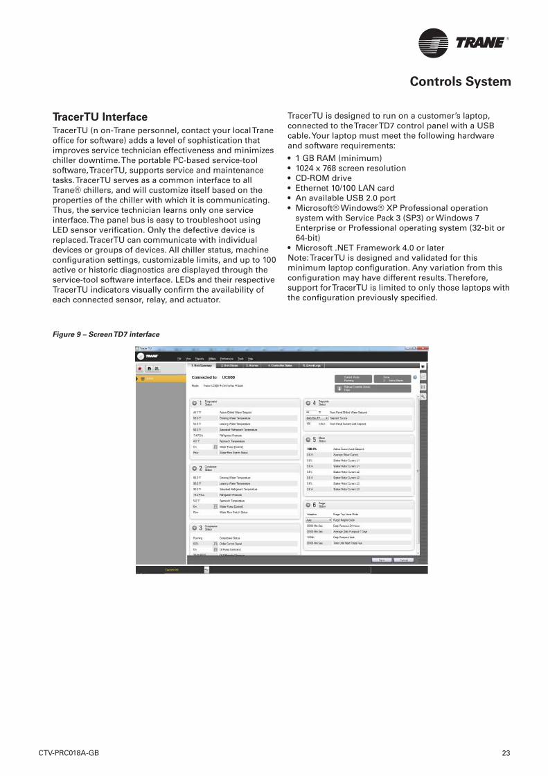
TracerTU Interface TracerTU (n on-Trane personnel, contact your local Trane offi ce for software) adds a level of sophistication that improves service technician effectiveness and minimizes chiller downtime. The portable PC-based service-tool software, TracerTU, supports service and maintenance tasks. TracerTU serves as a common interface to all Trane® chillers, and will customize itself based on the properties of the chiller with which it is communicating. Thus, the service technician learns only one service interface. The panel bus is easy to troubleshoot using LED sensor verifi cation. Only the defective device is replaced. TracerTU can communicate with individual devices or groups of devices. All chiller status, machine confi guration settings, customizable limits, and up to 100 active or historic diagnostics are displayed through the service-tool software interface. LEDs and their respective TracerTU indicators visually confi rm the availability of each connected sensor, relay, and actuator.
TracerTU is designed to run on a customer’s laptop, connected to the Tracer TD7 control panel with a USB cable. Your laptop must meet the following hardware and software requirements:
• 1 GB RAM (minimum) • 1024 x 768 screen resolution • CD-ROM drive • Ethernet 10/100 LAN card • An available USB 2.0 port • Microsoft® Windows® XP Professional operation
system with Service Pack 3 (SP3) or Windows 7 Enterprise or Professional operating system (32-bit or 64-bit)
• Microsoft .NET Framework 4.0 or later Note: TracerTU is designed and validated for this minimum laptop confi guration. Any variation from this confi guration may have different results. Therefore, support for TracerTU is limited to only those laptops with the confi guration previously specifi ed.
Figure 9 – Screen TD7 interface
CTV-PRC018A-GB 23

Controls System
System Integration
Stand-Alone ControlsSingle chillers installed in applications without a building management system are simple to install and control: only a remote auto/stop for scheduling is required for unit operation. Signals from the chilled-water pump contactor auxiliary, or a fl ow switch, are wired to the chilled-water fl ow interlock. Signals from a time clock or some other remote device are wired to the external auto/stop input.
• Auto/Stop-A job-site provided contact closure turns the unit on and off.
• External Interlock-A job-site provided contact opening wired to this input turns the unit off and requires a manual reset of the unit microcomputer. This closure is typically triggered by a job-site provided system such as a fi re alarm.
Hardwire Points Microcomputer controls allow simple interface with other control systems, such as time clocks, building automation systems, via hardwire points. This means you have the fl exibility to meet job requirements while not having to learn a complicated control system. Remote devices are wired from the control panel to provide auxiliary control to a building automation system. Inputs and outputs can be communicated via a typical 4–20 mA electrical signal, an equivalent 2–10 V dc signal, or by utilizing contact closures. This setup has the same features as a stand-alone water chiller, with the possibility of having additional optional features:
• External chilled water setpoint, external demand limit setpoint.
• Chilled water temperature reset.• Programmable relays - available outputs are: alarm-
latching, alarm-auto reset, general alarm-warning, chiller limit mode, compressor running, and Tracer control.
• BACnet Interface
• Tracer TD7 control can be confi gured for BACnet communications at the factory or in the fi eld. This enables the chiller controller to communicate on a BACnet MS/TP network. Chiller setpoints, operating modes, alarms, and status can be monitored and controlled through BACnet. Tracer TD7 controls conforms to the BACnet B-ASC profi le as defi ned by ASHRAE 135-2004.
• Lon Talk Communications Interface (LCI-C).
• The optional Lon Talk® Communications Interface for Chillers (LCI-C) is available factory or fi eld installed. It is an integrated communication board that enables the chiller controller to communicate over a LonTalk network. The LCI-C is capable of controlling and monitoring chiller setpoints, operating modes, alarms, and status. The Trane LCI-C provides additional points beyond the standard LONMARK® defi ned chiller profi le to extend interoperability and support a broader range of system applications. These added points are referred to as open extensions. The LCI-C is certifi ed to the LONMARK Chiller Controller Functional Profi le 8040 version 1.0, and follows LonTalk FTT-10A free topology communications.
Modbus Interface Tracer TD7 control can be confi gured for Modbus communications at the factory or in the fi eld. This enables the chiller controller to communicate as a slave device on a Modbus network. Chiller setpoints, operating modes, alarms, and status can be monitored and controlled by a Modbus master device.
Tracer Summit The chiller plant control capabilities of the Trane Tracer Summit™ building automation system are unequaled in the industry. Trane’s depth of experience in chillers and controls makes us a well-qualifi ed choice for automation of chiller plants using air-cooled GVAF chillers. Our chiller plant automation software is fully pre-engineered and tested.
Required features:
• LonTalk/Tracer Summit Interface (selectable option with chiller)
• Building Control Unit (external device required)• Sequences starting of chillers to optimize the overall
chiller plant energy effi ciency – Individual chillers operate as base, peak, or swing based on capacity and effi ciency
– Automatically rotates individual chiller operation to equalize runtime and wear between chillers
– Evaluates and selects the lowest energy consumption alternative from an overall system perspective.
• Regulatory Compliance Documentation• Gathers information and generates the reports
mandated in ASHRAE Guideline 3. • Easy Operation and Maintenance• Remote monitoring and control • Displays both current operation conditions and
scheduled automated control actions• Concise reports assist in planning for preventative
maintenance and verifying performanceAlarm notifi cation and diagnostic messages aid in quick and accurate troubleshooting.
CTV-PRC018A-GB24
Controls System
Tracer SC The Tracer SC™ system controller acts as the central coordinator for all individual equipment devices on a Tracer building automation system. The Tracer SC scans all unit controllers to update information and coordinate building control, including building subsystems such as VAV and chiller water systems. With this system option, the full breadth of Trane’s HVAC and controls experience are applied to offer solutions to many facility issues. The LAN allows building operators to manage these varied components as one system from any personal computer with web access.
The benefi ts of this system are:
• Improved usability with automatic data collection, enhanced data logging, easier to create graphics, simpler navigation, pre-programmed scheduling, reporting, and alarm logs.
• Flexible technology allows for system sizes from 30-120 unit controllers with any combination of LonTalk or BACnet unit controllers.
• LEED certifi cation through site commissioning report, energy data collection measurement, optimizing energy performance, and maintaining indoor air quality.
Energy savings programs include: fan pressure optimization, ventilation reset, and chiller plant control (adds and subtracts chillers to meet cooling loads).
Building Automation and Chiller Plant Control
The UC800 controller can communicate with Trane Tracer Summit, Tracer SC and Tracer ES building automation systems, which include pre-engineered and fl exible control for chiller plants. These building automation systems can control the operation of the complete installation: chillers, pumps, isolating valves, air handlers, and terminal units.
Trane can undertake full responsibility for optimized automation and energy management for the entire chiller plant.
The main functions are:
• Chiller sequencing: equalizes the number of running hours of the chillers. Different control strategies are available depending on the confi guration of the installation.
• Control of the auxiliaries: includes input/output modules to control the operation of the various auxiliary equipment (water pumps, valves, etc.).
• Time-of-day scheduling: allows the end user to defi ne the occupancy period, for example: time of the day, holiday periods and exception schedules.
• Optimization of the installation start/stop time: based on the programmed schedule of occupancy and the historical temperature records. Tracer Summit and Tracer SC calculate the optimal start/stop time of the installation to get the best compromise between energy savings and comfort of the occupants.
• Soft loading: the soft loading function minimizes the number of chillers that are operated to satisfy a large chilled-water-loop pull down, thus preventing an overshoot of the actual capacity required. Unnecessary starts are avoided and the peak current demand is lowered.
• Communication capabilities: local, through a PC workstation keyboard. Tracer Summit and Tracer SC can be programmed to send messages to other local or remote workstations and or a pager in the following cases: – Analog parameter exceeding a programmed value – Maintenance warning – Component failure alarm – Critical alarm messages. In this latter case, the message is displayed until the operator acknowledges the receipt of the information. From the remote station it is also possible to access and modify the chiller plants control parameters.
Remote communication through a modem: as an option, a modem can be connected to communicate the plant operation parameters through voice grade phone lines.
A remote terminal is a PC workstation equipped with a modem and software to display the remote plant parameters.
Integrated Comfort System (ICS)
The onboard Tracer chiller controller is designed to be able to communicate with a wide range of building automation systems. In order to take full advantage of chiller’s capabilities, incorporate your chiller into a Tracer Summit or Tracer SC building automation system. But the benefi ts do not stop at the chiller plant. At Trane, we realize that all the energy used in your cooling system is important. That is why we worked closely with other equipment manufacturers to predict the energy required by the entire system. We used this information to create patented control logic for optimizing HVAC system effi ciency. The building owners challenge is to tie components and applications expertise into a single reliable system that provides maximum comfort, control, and effi ciency. Trane Integrated Comfort systems (ICS) are a concept that combines system components, controls, and engineering applications expertise into a single, logical, and effi cient system. These advanced controls are fully commissioned and available on every piece of Trane® equipment, from the largest chiller to the smallest VAV box. As a manufacturer, only Trane offers this universe of equipment, controls, and factory installation and verifi cation.
CTV-PRC018A-GB 25
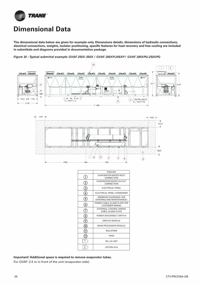
Dimensional Data
The dimensional data below are given for example only. Dimensions details, dimensions of hydraulic connections,
electrical connections, weights, isolator positioning, specifi c features for heat recovery and free cooling are included
in submittals and diagrams provided in documentation package.
Figure 10 – Typical submittal example: GVAF 250X-350X / GVAF 190XP-245XP / GVAF 190XPG-250XPG
ENGLISH
� EVAPORATOR WATER INLET CONNECTION
� EVAPORATOR WATER OUTLET CONNECTION
� ELECTRICAL PANEL
� ELECTRICAL PANEL CONDENSER
� MINIMUM CLEARANCE (AIR ENTERING AND MAINTENANCE)
� POWER CABLE GLAND PLATE FOR CUSTOMER WIRING
� EXTERNAL CONTROL WIRING CABLE GLAND PLATE
POWER DISCONNECT SWITCH
DISPLAY MODULE
� MAIN PROCESSOR MODULE
� ISOLATORS
FANS
SN_LN UNIT
OPTION XLN
Important! Additional space is required to remove evaporator tubes.
For GVAF: 2.5 m in front of the unit (evaporator side).
CTV-PRC018A-GB26
CTV-PRC018A-GB 27
Mechanical Specifi cations
General
Chilled water production will be made by a factory-assembled, air-cooled liquid chiller, Trane type GVAF X/XP/XPG. Chiller will have two refrigerant circuits with one or two compressors per circuit, will be shipped with a full operating charge of R134a refrigerant or R1234ze and centrifugal oil free compressor and electronic expansion valve.
Documentation including installation-operation-maintenance manual, user guide, wiring diagram and submittal is placed in the control panel.
Performances summary• Cooling capacity at full load:…. (kW)• Unit power input at full load:……(kW)• Operating conditions: Evaporator entering/leaving
temperature: …./…..(°C). Air temperature:……...(°C).
• Energy effi ciency at full load EER:………. (kW/kW)• European Seasonal Energy Effi ciency Ratio
ESEER:……. (kW/kW)• Sound power level:……… dB(A)
Quality assuranceChiller is designed and manufactured under a quality assurance system and enviromental management system certifi ed in accordance with ISO 9001:2008 and ISO14001 standards.
Chiller is factory-tested according standard EN14511, and performances are certifi ed by Eurovent. All chillers follow a production quality plan to ensure proper construction and operation.
Unit construction will be in accordance with follow European directives:
• Pressure Equipment Directive (PED) 97/23/CE• Machinery Directive (MD) 2006/42/CE• Low Voltage Directive (LV) 2006/95/CE• ElectroMagnetic Compatibility Directive (EMC)
2004/108/CE • Electrical Machinery Safety Standard EN 60204-1
Construction CharacteristicsUnit panels, frames and exposed steel surfaces will be constructed of galvanized steel, painted and have a corrosion resistance of 675 hours to salt spray test.
Electrical panel will be built of galavanized steel and rated IP54.
Compressors and MotorsThe centrifugal oil free compressor is two stage, semi hermetic and direct drive, powered by pulse width modulating voltage supply.
Compressor shall be constructed with cast aluminum casing and high-strength thermoplastic electronics enclosures.
The impellers shall consist of cast and machined aluminum.
The motor rotor and impeller assembly shall be the only major moving parts.
The compressor shall be provided with radial and axial magnetic bearings to levitate the shaft.
Each bearing position shall be sensed by position sensors to provide real-time repositioning of the rotor shaft, controlled by onboard digital electronics.
The compressor shall have a Variable Frequency Drive (VFD) for linear capacity modulation and reduced in-rush starting current.
Compressor shall equip with a bank of capacitor to storage energy and a EMC fi lter to avoid harmonic transfer to the compressor.
Motor cooling shall be by liquid refrigerant injection.
EvaporatorThe evaporator is a tube-in-shell heat exchanger design constructed from carbon steel shells and tubesheets with internally and externally fi nned seamless copper tubes mechanically expanded into the tube sheets. Tubes are cleanable with dismountable water boxes. Tubes diameter is 19mm. Each tube is individually replaceable.
The evaporator is designed, tested and stamped in accordance with PED 97/23/CE Pressure Vessel Code for a refrigerant side working pressure of 14 bars (200 psig). The evaporator is designed for a water side working pressure of 10.5 bars (150 psig). Standard water connections are grooved for Victaulic type pipe couplings. Waterboxes are available in 2 passes confi gurations and include a vent, a drain and fi ttings for temperature control sensors. Evaporator is insulated with Armafl ex II or equivalent of 19 mm (3/4 inches) thickness and K factor of 0,26 W/m²°K.
Mechanical Specifi cations
CTV-PRC018A-GB28
Condenser and FansThe air-cooled Microchannel condenser coils use all aluminum brazed fi n construction. The coil is composed of three components: the fl at microchannel tube, the fi ns located between the microchannel tubes, and two refrigerant manifolds. Coils can be cleaned with high pressure water.
The condenser coil has an integral subcooling circuit. The maximum allowable working pressure of the condenser is 25.0 bars. Condensers are factory proof and leak tested at 45 bars.
Direct-drive vertical-discharge airfoil condenser fans are dynamically balanced.
Units are equipped with EC condenser fan motors with permanently lubricated ball bearings and external overload protection are provided. Fans are class F, IP55.
Refrigerant CircuitEach unit has two refrigerant circuits, with one or two cenrtifugal compressors per circuit. Each refrigerant circuit includes compressor discharge service valves, motorized suction valve, liquid line shut off valve, removable core fi lter, charging port, high pressure and low pressure safety valves and electronic expansion valve.
Electrical PanelSingle point connection with disconnect switch and fuses.
The disconnect switch is mechanically interlocked to disconnect line power from the starter before the starter doors are open.
All components and control cables are numbered in accordance with CEI 60750.
A factory-installed, factory-wired control power transformer provides all unit control power and UC800 module power. All the starter elements are enclosed in an IP54 panel, with hinged door.
Unit Controls (Tracer UC800)The microprocessor-based control panel is factory-installed and factory-tested.
Microprocessor-based chilled water reset based on return water is standard. The UC800 utilizing the “Adaptive Control™” microprocessor automatically takes action to prevent unit shutdown due to abnormal operating conditions associated with low evaporator refrigerant temperature, high condensing temperature, and motor current overload. If abnormal operating condition continues and protective limit is reached, the refrigerant circuit will be shut down. Controller includes machine protection shutdown requiring manual reset for:
• Low evaporator refrigerant temperature and pressure• High condenser refrigerant pressure• Critical sensor or detection circuit fault• Motor current overload• High compressor discharge temperature• Communications lost between modules• Electrical distribution faults: phase loss, phase
imbalance, phase reversal• External and local emergency stop• Starter transition failure.The panel includes machine protection shutdown with automatic reset when the condition is corrected for:
• Momentary power loss• Over / under voltage• Loss of evaporator water fl ow.Over 100 diagnostic checks is made and are displayed when a fault is detected. The display indicates the fault, the type of reset required, the time and date the diagnostic occurred, the mode in which the machine was operating at the time of the diagnostic, and a help message. A diagnostic history displays the last 20 diagnostics with the time and date of their occurrence. Alarms and diagnostics are displayed in chronological order, with a color/symbol code: red octagon for immediate shutdown, yellow triangle for normal shutdown and blue circle for warning.
CTV-PRC018A-GB 29
Mechanical Specifi cations
Human interface with Touchable Display Trane TD7
• Factory-mounted above the control panel door• UV Resistant touchscreen• -40°C to 70°C operating temperature• IP56 rated • CE certifi cation• Emissions: EN55011(Class B)• Immunity: EN61000 (Industrial)• 7” diagonal• 800x480 pixels• TFT LCD @ 600 nits brightness• 16 bit color graphic display
Display features:
• Alarms• Reports• Chiller settings• Display settings• Graphing• Support for 15 languages
Dry contacts
UC800 provides a fl exible alarm or chiller status indication to a remote location through a hard wired interface to a dry contact closure. Four relays are available for this function.
Options
Application options
Integrated Variable Primary Flow
Integrated within the chiller controller, a variable primary fl ow option will allow control of the water fl ow through the evaporator. This will be based on a proven algorithm modulating the fl ow rate to minimize pump consumption at full and partial load. Two options of operating modes will be available:
Constant Differential Pressure (DP), acting continuously on the pump speed to ensure a constant outlet pressure. This solution is recommendable on installations with 2-way valves on the water coils. This method ensures that each branch of the water loop has an uniform supply, without unnecessary energy consumption. This system will ensure that each water terminal has the appropriate differential pressure supply. In order to manage chiller minimum evaporator water fl ow, a hydronic package will include water pressure transducers to intelligently monitor water fl ow rate in real time within AdaptiView™ chiller control. Chiller will deliver control signal for system by-pass valve actuator. System differential pressure is measured by supplied differential pressure transducer.
Constant Differential Temperature (DT), in this case the chiller controller algorithm will maintain a constant difference in between entering and leaving temperature at the chiller plant (DT), regardless the load, reducing the water fl ow rate when necessary up to the minimum allowed. This solution can be applied on water loops with 3-way valves systems, and can deliver higher energy saving than precedent logic (constant DP) in the majority of the comfort applications.
Free-cooling Control
Chiller controller could supply a control option for an externally supplied dry cooler to implement free-cooling strategy, allowing as per pre-fi xed ambient temperature set point, switch from chiller operation to dry cooler operation. Control algorithm will be based on PID logic, return temperature and cooling capacity demand.
Free-cooling Chiller
Chiller can be supplied with option for water based free-cooling, built with all aluminum fl at channel dry cooler exchanger, installed in parallel with refrigerant microchannel condenser coil, and a water valve to control the free-cooling capacity. Follow options shall be available:
- Total Direct Free-cooling- Partial Direct Free-cooling- Total Glycol free Free-cooling- Partial Glycol free Free-cooling
E-coating
An option to supply MCHE condenser coils with e-coating will be available. This e-coating will withstand the exposure to typical corrosive atmospheres, in shore or industrial locations, without sensible impact on coil performances in what heat transfer and air pressure drop is a concern.
Sound level options
Low noise
All GVAF units are equipped with EC fans, compressors are enclosed in a box and discharge line insulated.
Low noise with NNSB
Night noise set back allow to reduce the sound level of the chiller by reducing the speed of EC fans controlled with an external on/off contact.
Extra low noise
Extra low noise units are equipped with NNSB and fan diffusers.
Hydraulic module option*Hydraulic module includes the following components: water strainer, 80 l expansion vessel, pressure relief valve set at 5 bars, twin pump low head allowing a pressure drop in the water circuit up to 120 kPa or twin pump high head allowing a pressure drop in the water circuit up to 220 kPa, balancing valve and anti freeze protection.
Electrical options• IP20 internal protection• Flow switch: the fl ow switch is sent as an accessory
and must be installed on site.
Control options
BACnet™ communications interface
Allows the user to easily interface with BACnet via a single twisted pair wiring to a factory installed and tested communication board.
LonTalk™ (LCI-C) Communications Interface
Provides the LonMar chiller profi le inputs/outputs for use with a generic building automation system via a single twisted pair wiring to a factory installed and tested communication board.
ModBus™ Communications Interface
Allows the user to easily interface with ModBus via a single twisted pair wiring to a factory installed and tested communication board.
External chilled water setpoint
UC800 accepts either a 2-10 VDC or a 4-20mA input signal, to adjust the chilled water setpoint from a remote location.
External current limit setpoint
UC800 accepts either a 2-10VDC or a 4-20mA input signal to adjust the current limit setpoint from a remote location.
Run test report
Run test report gives the results of the perfomance test of the unit in the design conditions specifi ed in the order write-up with water without glycol.
The data recorded are: cooling capacity, power input, air temperature, water entering temperature, water leaving temperature and water fl ow.
Other Options
Relief valves
Dual relief valve plus 3-way valve on high and low pressure side.
High performance insulation.
Evaporator is insulated with 2 layers of Armafl ex II or equivalent of 19 mm (3/4 inches) thickness and K factor of 0,26 W/m²°K.
Evaporator without insulation
Evaporator is not insulated and a specifi c insulation can be done on site.
Coated condensing coils
Condensing coils are protected with a cathodic epoxy electrodeposition coating UV resistant
Neoprene pads
Neoprene pads avoids a direct contact of the base of the unit with the ground
Neoprene isolators
Isolators provide isolation between chiller and structure to help eliminate vibration transmission and have an effi ciency of 95% minimum
Grooved pipe plus weld coupling
Grooved pipes are connected on water inlet and outlet. The coupling allows connection between the grooved pipe and the evapoator water connection.
Export shipping package
Metallic clogs are fi xed on the base frame of the unit. They prevents direct contact between the chiller and the container during loading and unloading from the container.
* Components may differ depending on unit model and size. Contact your local sales offi ce for details.
Mechanical Specifi cations
CTV-PRC018A-GB30
Notes
CTV-PRC018A-GB 31
Trane optimizes the performance of homes and buildings around the world. A business of Ingersoll Rand, the leader in creating and sustaining safe, comfortable and energy effi cient environments, Trane offers a broad portfolio of advanced controls and HVAC systems, comprehensive building services and parts. For more information visit www.Trane.com
Trane has a policy of continuous product and product data improvement and reserves the right to change design and specifi cations without notice.
© 2016 Trane All rights reserved
CTV-PRC018A-GB August 2016New
We are committed to using environmentallyconscious print practices that reduce waste.