air cooled scroll chiller / heat pump · the controller changes the chiller’s capacity by either...
TRANSCRIPT

Air Cooled Scroll Chiller / Heat Pump
SRA 290
Nominal Capacity 255 to 1530 kW Refrigerant: R407c and R134a

Contents
Features 1
MV7 Control 3
Physical Data 5
Unit Performance 7
Chiller Selection 8
Physical Dimension 9
Piping Schematic 10
Power Connection 11
Field Wiring Diagram 12
Electrical Data 13
09/2018 Rev.1.0
1
Features
STRUCTURE
MULTISTACK Air Cooled Chillers are designed and constructed under the modular technology patent. A chiller bank consists of multiple individual chiller modules connected in parallel to operate as a single machine, with cooling or heating capacity to match the load demand by varying the number of operating module, and are expandable to eight full modules.
Each full module consists of two tandem scroll compressor sets (4 compressors), evaporator, condenser, four fans, and sophisticated control and protection equipment. Each module operates as a completely independent refrigeration circuit, and varying to the total load demand. The controller changes the chiller’s capacity by either controlling the number of modules in operation or by adjusting the capacity of the last start up compressor.
The Multistack Air Cooled line-up is available in cooling-only version or heat pump version for dual operation.
COMPACT AND SPACE-SAVING
The compact size of each module means easy access via standard lifts. You no longer need special access to install the chiller.
LOWER INSTALLATION COST Connection of the modules has never been simpler – only two pipes to connect followed by communication cables and you’re in business.
ADD-ON FLEXIBILITY
As your needs for cooling or heating increases, Multistack has the solution. Being a modular chiller, it has never been easier to expand the system as larger cooling capacity is needed to meet increased building load demands, with no complicated changes to the room, piping system or control system, and all work can be done quite easily. As many as 8 full modules can be connected together as a chiller bank.
SAFE AND RELIABLE Every module works as an independent refrigeration circuit, with adjacent modules operating independently. In the event of a malfunction in the system, the computer selects the next available standby module to provide back up. One failed module will not disrupt the other chillers or system, giving you total peace of mind.
PEAK ECONOMY AT ALL LOADS Automatic scheduling of the compressors allows the chiller to match the fluctuating cooling/heating loads and conserve energy with each individual unit running at its peak efficiency. This is much more economical when compared to a large single unit running at part load.
UNPARALLELED RELIABILITY Every Multistack slave module is identical to each other, so in the event of a malfunction in the system, the computer automatically selects the next available standby circuit to provide back up. For critical air conditioning and industrial process cooling a Multistack modular chiller inherently provides economical standby capacity and unparalleled dependability.
HIGH EFFICIENCY, QUIET OPERATING SCROLL COMPRESSOR
Scroll compressors produce less vibration and are quieter than that of their hermetic counterparts (due to absence of dynamic suction and discharge valves and a much smoother compression process).
EVAPORATOR
Stainless steel 316 brazed plate heat exchanger; Vacuum brazed, endure working pressure of 2.0MPa, small size and light weight, high heat transfer efficiency.

09/2018 Rev.1.0
2
PRE-CHARGED REFRIGERANT
R407C and R134a available for standard chiller; less refrigerant charge required and the refrigerant charged prior to shipment and undergone performance test
INTERNAL WATER STRAINER
Internal water strainer is made under the Multistack’s patent technology, and made from stainless steel. Internal water strainers are supplied and fixed inside both chilled water header pipes and condenser water header pipes for each module. It can be easily dismantled and removed. The internal water strainer can prevent particles contained in the water from getting into the heat exchanger.
MODEL NUMBER DESIGNATION
SR A 290 C - 5 A B R V
1 2 3 4 5 6 7 8 9
1: Scroll compressor
2: Cooling type:
A: Air cooled W: Water cooled
3: Model Number
4: Chiller type
C: Cooling Only
H: Heat Pump
5: The number of modules per chiller (1 – 6)
6: Electrical Specifications
A: 400V ± 10%, 50Hz, 3 Phase
B: 380V, 60Hz, 3 Phase
C: 440-460V, 60Hz, 3 Phase
7: Configuration
B: Back to Back (Standard)
8: Refrigerant
E: R134a
R: R407c
9. Fan
V: Variable Speed Drive (VSD)
Blank for Standard

09/2018 Rev.1.0
3
MV7 Control The MV7 computer monitors the chiller's operation and schedules the on and off of each compressor and capacity control stages with respect to the change in load demand. The computer continuously and comprehensively monitors the total operation of all modules in the chiller bank. It will also shut down individual module or the entire bank in the event that a fault occurs. A maximum of 32 refrigeration circuits can be monitored at one time.
SYSTEM DATA AND VARIABLES DISPLAY
The controller’s 7” touch panel not only can display the chiller’s operation data but also provides direct access to all of the chillers setting and variables for total system control.
Chiller operation status
chilled water temperature
condenser water temperature
% of chiller cooling capacity
% demand loading
load / unload time delay
current fault number
% of loading limitation
lead compressor
Module operation status
compressor suction pressure
compressor discharge pressure
evaporating temperature
chilled water leaving temperature
faults status
Chiller variables settings
password
chilled water temperature
lead compressor
temperature integrating time
economy offset
load / unload time delay
time and date
COMPRESSOR SEQUENCE
The MV7 controller accumulates the running hours of each compressor and hence establishes working sequence. A standby compressor with the least working hours will be activated during loading. The same goes for a compressor with the most working hours will be stopped during unloading. This ensures each compressor in the system has an even usage, which will save you time and money in the long run for maintenance.
FAULT REVIEW The controller will record and display the last 60 faults that occurred, giving detailed information such as time, date, location, cause, current status, as well as the performance data collected at the moment each fault occurred.
LOAD PROFILE The controller records all working hours of the chiller and compressor and records it accordingly in 10% brackets from 0% - 100%, giving you detailed information for which percentage the chiller is running mostly.

09/2018 Rev.1.0
4
PASSWORD
A two level password protection is included (for both customer and service personnel) to give you piece of mind. For example the service password will give you full access to settings and variables, but the user password will only enable the user see but not change settings and variables.
STANDBY CONTROL
Each module can be set for three modes: auto/ off/independent operation via the slave outstation card installed in the module. Default setting is “auto”, with “off” mode for when maintenance is required and “independent” mode (where the module is controlled by its own slave outstation card and operates independently from the controller), is usually for commissioning or emergency operation.
REMOTE CONTROL & MONITORING (OPTIONAL)
1) If direct RCM functionality is required, the MV7 HMI computer will be assembled with an Ethernet port, allowing it to be fully managed from a remote computer via a VNC Client/ Server protocol.
2) If BAS Communication is required, the MV7 System will be fitted with a BACnet IP/MSTP Gateway.
09/2018 Rev.1.0
5
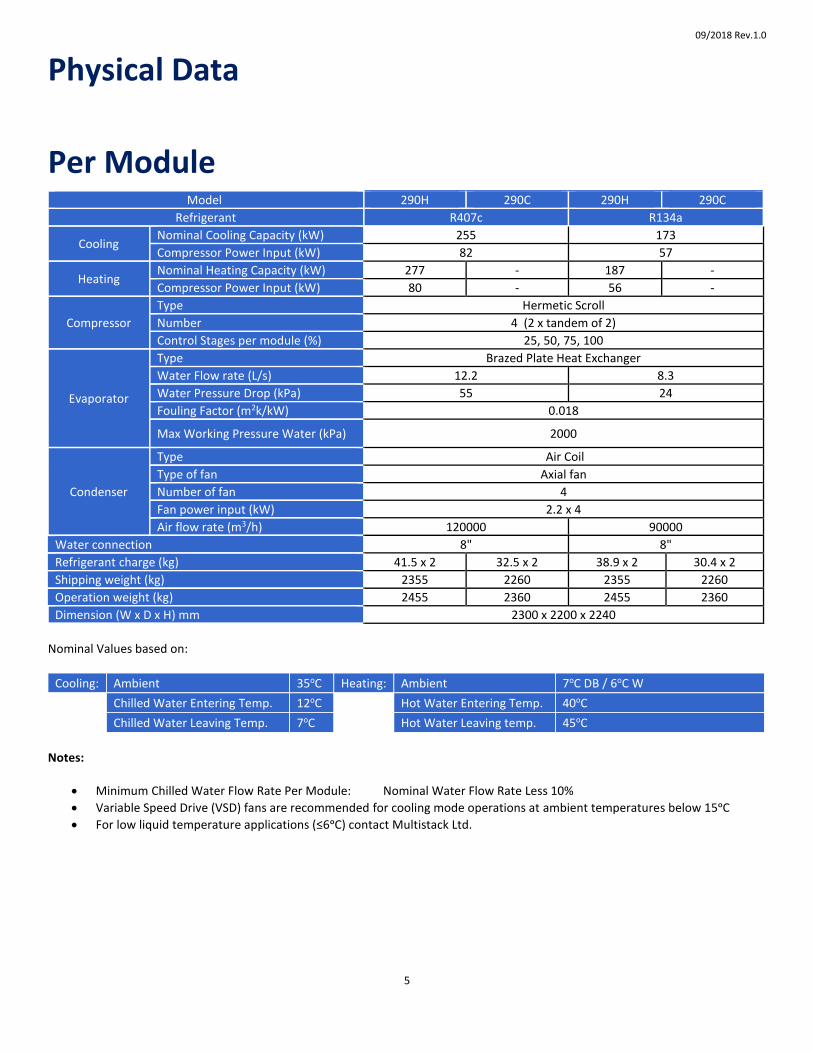
Physical Data
Per Module Model 290H 290C 290H 290C
Refrigerant R407c R134a
Cooling Nominal Cooling Capacity (kW) 255 173
Compressor Power Input (kW) 82 57
Heating Nominal Heating Capacity (kW) 277 - 187 -
Compressor Power Input (kW) 80 - 56 -
Compressor
Type Hermetic Scroll
Number 4 (2 x tandem of 2)
Control Stages per module (%) 25, 50, 75, 100
Evaporator
Type Brazed Plate Heat Exchanger
Water Flow rate (L/s) 12.2 8.3
Water Pressure Drop (kPa) 55 24
Fouling Factor (m2k/kW) 0.018
Max Working Pressure Water (kPa) 2000
Condenser
Type Air Coil
Type of fan Axial fan
Number of fan 4
Fan power input (kW) 2.2 x 4
Air flow rate (m3/h) 120000 90000
Water connection 8" 8"
Refrigerant charge (kg) 41.5 x 2 32.5 x 2 38.9 x 2 30.4 x 2
Shipping weight (kg) 2355 2260 2355 2260
Operation weight (kg) 2455 2360 2455 2360
Dimension (W x D x H) mm 2300 x 2200 x 2240
Nominal Values based on:
Cooling: Ambient 35oC Heating: Ambient 7oC DB / 6oC W
Chilled Water Entering Temp. 12oC
Hot Water Entering Temp. 40oC
Chilled Water Leaving Temp. 7oC Hot Water Leaving temp. 45oC
Notes:
Minimum Chilled Water Flow Rate Per Module: Nominal Water Flow Rate Less 10%
Variable Speed Drive (VSD) fans are recommended for cooling mode operations at ambient temperatures below 15ᵒC
For low liquid temperature applications (≤6ᵒC) contact Multistack Ltd.

09/2018 Rev.1.0
6
HEAT EXCHANGER WATER PRESSURE DROP
PRESSURE DROP CORRECTION FACTOR (𝜉)
1. Water pressure drop calculation
Water flow % =𝐴𝑐𝑡𝑢𝑎𝑙 𝑤𝑎𝑡𝑒𝑟 𝑓𝑙𝑜𝑤
𝑁𝑜𝑚𝑖𝑛𝑎𝑙 𝑤𝑎𝑡𝑒𝑟 𝑓𝑙𝑜𝑤 × 100
Heat exchanger actual water pressure drop per module = heat exchanger nominal water pressure drop × 𝜉 𝛽 is related to total number of modules (N) in the chiller bank
Total water pressure drop per chiller =heat exchanger actual water pressure drop per module × 𝛽 2. Chiller minimum working water flow (1) Constant water flow system, no less than 90% of chiller total nominal water flow (2) Variable water flow system: no less than 90% of module nominal water flow
N 1 2 3 4 5 6
𝛽 1.00 1.00 1.01 1.02 1.03 1.04
Pressure drop correction factor for chilled and hot water circuit
09/2018 Rev.1.0
7
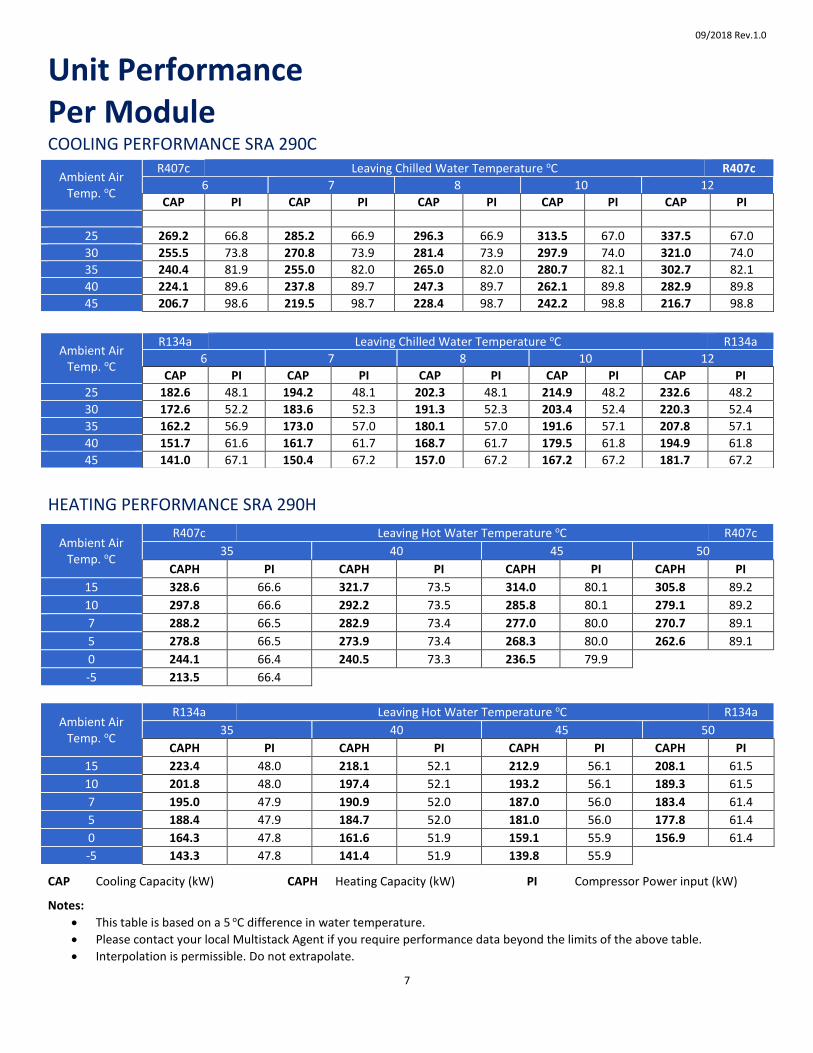
Unit Performance Per Module COOLING PERFORMANCE SRA 290C
HEATING PERFORMANCE SRA 290H
Ambient Air Temp. oC
R407c Leaving Hot Water Temperature oC R407c
35 40 45 50
CAPH PI CAPH PI CAPH PI CAPH PI
15 328.6 66.6 321.7 73.5 314.0 80.1 305.8 89.2
10 297.8 66.6 292.2 73.5 285.8 80.1 279.1 89.2
7 288.2 66.5 282.9 73.4 277.0 80.0 270.7 89.1
5 278.8 66.5 273.9 73.4 268.3 80.0 262.6 89.1
0 244.1 66.4 240.5 73.3 236.5 79.9
-5 213.5 66.4
Ambient Air Temp. oC
R134a Leaving Hot Water Temperature oC R134a
35 40 45 50
CAPH PI CAPH PI CAPH PI CAPH PI
15 223.4 48.0 218.1 52.1 212.9 56.1 208.1 61.5
10 201.8 48.0 197.4 52.1 193.2 56.1 189.3 61.5
7 195.0 47.9 190.9 52.0 187.0 56.0 183.4 61.4
5 188.4 47.9 184.7 52.0 181.0 56.0 177.8 61.4
0 164.3 47.8 161.6 51.9 159.1 55.9 156.9 61.4
-5 143.3 47.8 141.4 51.9 139.8 55.9
CAP Cooling Capacity (kW) CAPH Heating Capacity (kW) PI Compressor Power input (kW)
Notes:
This table is based on a 5 oC difference in water temperature.
Please contact your local Multistack Agent if you require performance data beyond the limits of the above table.
Interpolation is permissible. Do not extrapolate.
Ambient Air Temp. oC
R407c Leaving Chilled Water Temperature oC R407c
6 7 8 10 12
CAP PI CAP PI CAP PI CAP PI CAP PI
25 269.2 66.8 285.2 66.9 296.3 66.9 313.5 67.0 337.5 67.0
30 255.5 73.8 270.8 73.9 281.4 73.9 297.9 74.0 321.0 74.0
35 240.4 81.9 255.0 82.0 265.0 82.0 280.7 82.1 302.7 82.1
40 224.1 89.6 237.8 89.7 247.3 89.7 262.1 89.8 282.9 89.8
45 206.7 98.6 219.5 98.7 228.4 98.7 242.2 98.8 216.7 98.8
Ambient Air Temp. oC
R134a Leaving Chilled Water Temperature oC R134a
6 7 8 10 12
CAP PI CAP PI CAP PI CAP PI CAP PI
25 182.6 48.1 194.2 48.1 202.3 48.1 214.9 48.2 232.6 48.2
30 172.6 52.2 183.6 52.3 191.3 52.3 203.4 52.4 220.3 52.4
35 162.2 56.9 173.0 57.0 180.1 57.0 191.6 57.1 207.8 57.1
40 151.7 61.6 161.7 61.7 168.7 61.7 179.5 61.8 194.9 61.8
45 141.0 67.1 150.4 67.2 157.0 67.2 167.2 67.2 181.7 67.2

09/2018 Rev.1.0
8
(2) Heating CAP= 277 kW per SRA 290H module
Required Number of Modules (N) = Heating Capacity Required
CAP per Module
= 1650 𝑘𝑊
277 𝑘𝑊= 6.0
Select 6 modules
The total heating capacity of the chiller is:
Number of Modules x CAP = 6 × 277 = 1662 kW
The capacity residue =(1662 − 1650)
1650× 100% = 0.73%
The calculation result is acceptable
(2) Hot Water Flow (HWF)
HWF = 𝑅𝑒𝑞𝑢𝑖𝑟𝑒𝑑 𝐻𝑒𝑎𝑡𝑖𝑛𝑔 𝐶𝐴𝑃
4.187 ×(𝐻𝑊𝐿𝑇−𝐻𝑊𝐸𝑇)=
1650
4.187×(45−40)
= 78.8 𝐿/𝑠
Chiller Selection
SELECT AIR-COOLED CHILLER ACCORDING TO FOLLOWING CONDITIONS:
1. Required Cooling Capacity…………………………………………………………………………………….1500 kW 2. Required Heating Capacity…………………………………………………………………………………….1650 kW 2. Entering Chilled Water Temperature (ECHW)................................................................ 12 °C 2. Leaving Chilled water Temperature (LCHW).................................................................... 7 °C 3. Ambient Temperature................................................................................................. 35.0 °C 4. Leaving Hot Water Temperature................................................................................. 45.0 °C 5. Entering Hot Water Temperature................................................................................ 40.0 °C 6. Ambient Temperature (AT)............................................................................................. 7.0 °C 7. Refrigerant..................................................................................................................... R407C Calculation 1. Determine Water Flow (CHWF) (L/s)
(1) Chilled Water Flow (CHWF)
CHWF = 𝑅𝑒𝑞𝑢𝑖𝑟𝑒𝑑 𝐶𝑜𝑜𝑙𝑖𝑛𝑔 𝐶𝐴𝑃
4.187 ×(𝐸𝐶𝐻𝑊−𝐿𝐶𝐻𝑊)=
1500
4.187×(12−7)
= 71.7 𝐿/𝑠
Note: Flow rate must not be less than Required Nominal Flow
2. From capacity chart above,
1 module at stated conditions will achieve;
(1) Cooling CAP= 255 kW per SRA 290H module
Required Number of Modules (N) = Cooling Capacity Required
CAP per Module
= 1500 𝑘𝑊
255 𝑘𝑊= 5.9
Select 6 modules
The total cooling capacity of the chiller is:
Number of Modules x CAP = 6 × 255 = 1530 kW
The capacity residue =(1530 − 1500)
1500× 100% = 2.0 %
The calculation result is acceptable
3. Chilled water pressure drop calculation
(1) Nominal Water Flow = N x Evaporator Water Flow
= 6 x 12.2 = 73.2 L/s
(2) Evaporator water pressure drop for nominal water flow per module is 55 kPa
Use the table Pressure drop correction factor: β, β=1.04 for the configuration: 6 modules.
Actual Evaporator water pressure drop is = 55 × 1.04 = 57.2 kPa

09/2018 Rev.1.0
9
Physical Dimensions
Notes:
All installations must have:
Description Remarks
3/8” BSP socket in all water connections adjacent to chiller for Multistack sensor installation.
Supplied by manufacturer
40 Mesh stainless strainers in water inlet piping
1. Only one computer installed per chiller bank. 2. Chilled water connections can be at either or both ends of chiller (optional). 3. Chiller to be mounted on 4 x 100sq. RHS positioned as shown (RHS not supplied by manufacturer). 4. Rails must be mounted on machinery mounting pads (not supplied by manufacturer)

09/2018 Rev.1.0
10
Water Piping Schematic CHILLED WATER PIPING
Item Description Qty Remarks
1 Drain Valve DG50 2 Supplied by others
2 Chilled Water Temp Sensor 2 Supplied by manufacturer
3 Pressure Gauge 2
Supplied by others
4 Vibration Eliminator 2
5 Isolation Gate Valve 5
6 Water Pump
7 Water Strainer 1
8 Chiller side differential pressure by-pass valve 1
9 Terminal air handling equipment
10 Motorized valve 1
11 Water flow switch 1 Supplied by others
12 Back Flush By-Pass Valve (*) 1 Supplied by others
Notes:
1. It is customer's responsibility for all piping parts, except those included with the chiller.
2. During the whole installation process, the isolation gate valves on both entering/leaving line to the chiller should be closed. The valves will remain closed until the piping installation; leakage check and cleaning are all completed.
3. To prevent stress on the headers and Victaulic couplings all water pipe work must be properly supported.
4. To prevent water accumulation inside the sensor socket grease should be filled in the sensor socket before inserting the chilled water temperature sensor.
5. (*) The chiller’s piping system should be cleaned thoroughly to get rid of any mechanical debris prior to operation. During pipe cleaning, close chiller’s entering/leaving isolation gate valves and open the bypass valve to prevent the water circulation through the chiller.
6. (*) During chiller operation, the back flush by-pass valve must be closed.

09/2018 Rev.1.0
11
Power Connection
No. of Modules Mains Termination
Location Connection Procedure
1.0 – 6.0 Module Electrical Cubicle Terminal Block
Notes: Supply 400V ± 10% / 50Hz / 3 phase 1. Design running current is the steady state current draw at a particular set of conditions, ie ambient and chilled water
temperatures. 2. Maximum rated current (MRC) is the maximum expected current drawn at transient (pull down) and/or greater than
design conditions.
CABLE SIZING
Power cables must be connected to each individual module.
When selecting mains cable sixe use RLA.
Allowances must be made for voltage imbalance, ambient temperature and other conditions in compliance with AS 3000 or local relevant electrical codes.
Power distribution cabinet (supplied by customer) should provide equal numbers of power cables connecting to each module.
09/2018 Rev.1.0
12
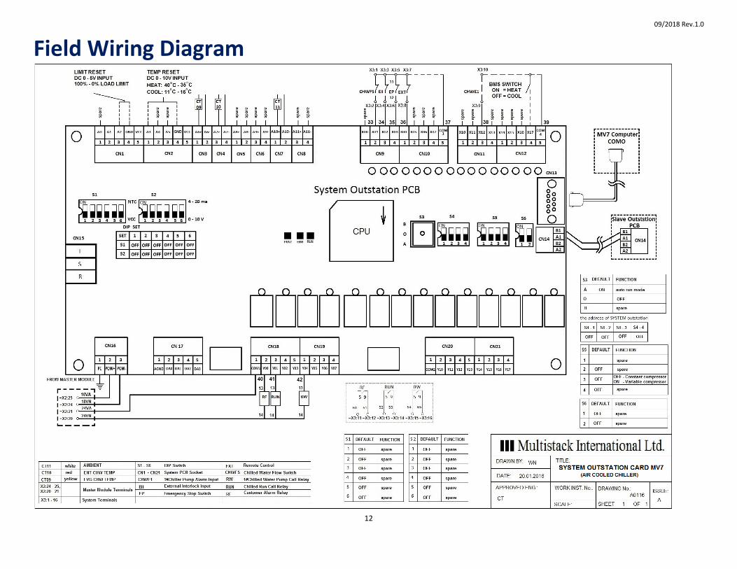
Field Wiring Diagram
09/2018 Rev.1.0
13
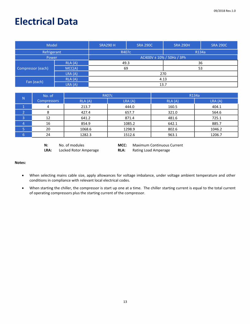
Electrical Data
Model SRA290 H SRA 290C SRA 290H SRA 290C
Refrigerant R407c R134a
Power AC400V ± 10% / 50Hz / 3Ph
Compressor (each)
RLA (A) 49.3 36
MCC(A) 69 53
LRA (A) 270
Fan (each) RLA (A) 4.13
LRA (A) 13.7
N No. of
Compressors
R407c R134a
RLA (A) LRA (A) RLA (A) LRA (A)
1 4 213.7 444.0 160.5 404.1
2 8 427.4 657.7 321.0 564.6
3 12 641.2 871.4 481.6 725.1
4 16 854.9 1085.2 642.1 885.7
5 20 1068.6 1298.9 802.6 1046.2
6 24 1282.3 1512.6 963.1 1206.7
N: No. of modules MCC: Maximum Continuous Current
LRA: Locked Rotor Amperage RLA: Rating Load Amperage
Notes:
When selecting mains cable size, apply allowances for voltage imbalance, under voltage ambient temperature and other conditions in compliance with relevant local electrical codes.
When starting the chiller, the compressor is start up one at a time. The chiller starting current is equal to the total current of operating compressors plus the starting current of the compressor.

MULTISTACK INTERNATIONAL LIMITED
17 FRIARS ROAD, MOORABBIN, VICTORIA 3189, AUSTRALIA
TELEPHONE: +61 3 8586 8200 FACSIMILE: +61 3 8586 8202
Email: [email protected]
Web site: http://www.multistack.com.au/
Since MULTISTACK INTERNATIONAL LIMITED has a policy of continuous product improvement, it reserves the right to change design and specification without notice.
Multistack supplied by Multistack Australia Pty Ltd (a wholly owned subsidiary of Multistack International Limited)
09/2018 Rev. 1.0