air nozzles pet blow molding compressor cooling
TRANSCRIPT

Air Nozzles PET Blow Molding Compressor CoolingM a r c h 2 0 0 7
TM

FLOWS TO 3,750 SCFM • PRESSURE TO 1,000 PSIG • AIR QUALITY TO ISO 8573-1 CLASS 1:4:1
FILTRATION TO 0.0008 PPMW/W • COLDWAVETM 316SS HEAT EXCHANGERS • WORLDWIDE DIS TRIBUTION
ColdWave™ high-pressure refrigerated air dryers and HF Series high-pressure filters protect your blowmolding and thermoforming
operations from damaging dirty, wet compressed air. Since 1948, engineers from around the world have specified energy-efficient
Hankison products to reduce operating costs and keep their air systems clean and dry.
Trust Hankison for performance under pressure.
© 2007 SPX Corporation
A 30% Energy Savings—
Its Money in the Bank
Innovation by Atlas Copco ZD series compressor systems
In today's competitive PET market, bottle cost reduction is the key to unlock a great
saving potential and to directly improve your bottom line. Atlas Copco’s new ZD series
reduces your energy bill by up to 30%, thanks to the winning combination of a VSD
screw compressor and a VSD booster. Installation cost is minimal and brings more
savings: the ZD comes as a complete package that requires no special foundation or
floor fixation. Its sound-insulated canopy allows it to be placed anywhere in the plant
without the need for an expensive compressor room. In short, the new ZD series will
put a big smile on your piggy bank!
www.atlascopco.com
Atlas Copco Compressors LLC1-800-232-3234
BEST PRACTICES | 0 3 / 0 7 Focus Industry | PLASTICS BLOW MOLDINGCOMPRESSED AIR
4 www.airbestpract ices.com
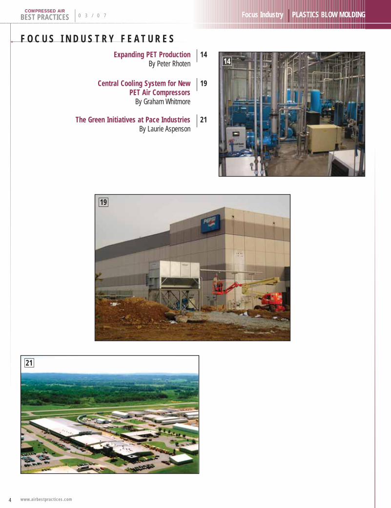
F O C U S I N D U S T R Y F E A T U R E SExpanding PET Production | 14
By Peter Rhoten
Central Cooling System for New | 19PET Air Compressors
By Graham Whitmore
The Green Initiatives at Pace Industries | 21By Laurie Aspenson
14
19
21
6
BEST PRACTICES | 0 3 / 0 7 Compressed Air Industry | PLASTICS BLOW MOLDINGCOMPRESSED AIR
www.airbestpract ices.com
C O M P R E S S E D A I R I N D U S T R Y A R T I C L E S
34
39
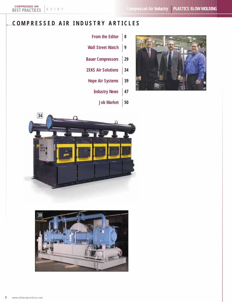
From the Editor | 8
Wall Street Watch | 9
Bauer Compressors | 29
ZEKS Air Solutions | 34
Hope Air Systems | 39
Industry News | 47
Job Market | 50
29

8
BEST PRACTICES | 0 3 / 0 7 Compressed Air Industry | PLASTICS BLOW MOLDING
www.airbestpract ices.com
COMPRESSED AIR
F R O M T H E E D I T O RHigh-Pressure Opportunities
High-pressure air, for most compressed
air industry professionals, represents any
application, above roughly 300 psig.The
majority of standard industrial, flat-top roof,
plant-air applications run at “medium”
pressures between 75–150 psig or at
“low” pressures between 7–40 psig.
High-pressure air, between 300–7,000
psig, is used in many applications and provides opportunities
in many industrial processes, including blow molding.
Opportunities exist, for energy savings, at PET stretch blow
molding facilities. In this edition, Mr. Peter Rhoten, provides
an interesting account of how separating the pressure
requirements, at a PET facility, creates energy savings.The
facility needed three pressures of compressed air (110 psig,
500 psig and 620 psig). Most of the lower pressures were
supplied by regulating down the high-pressure air. Creating
dedicated piping loops and supply sources, for the different
pressures,provided the facility with energy saving opportunities.
Injection and extrusion blow molders, may have opportunities
to improve the efficiencies of the air nozzles used in open-
blowing processes.Air nozzles are one of the first things
examined in a blow molder’s air system.Mr. Hank Van Ormer
provides an analysis of nozzles, in this edition,which are capable
of amplifying the volume of compressed air.This amplification
of volume reduces the amount of compressed air needed,
for the blowing application, in the blow molding system.
Industry has many applications, which are satisfied by high-
pressure compressed air. Bauer Compressors, a world-wide
leader in high pressure compressors, shares some of the
many applications they serve, in the pages of this edition.
The applications, to name a few, range from leak detection,
instrument calibration, relief valve testing, seismographic
exploration, and even pneumatic rams designed to test seat
belts. High-pressure compressed air, at pressures between
300–7,000 psig, make these processes possible.
As a person who has done most of my work at medium-
pressures, I find the high-pressure opportunities, for energy-
savings and for innovative applications, very interesting.
I hope you do as well.
ROD SMITH
“Compressed air, .
at 300–7000 psig,
has many industrial
applications.”
Compressed Air Best Practices is published monthlyby Smith Onandia Communications LLC., 161Clubhouse Circle, Fairhope, AL, 36532. Phone (251)510-2598. Publisher cannot be held liable for non-delivery due to circumstances beyond its control. No refunds. SUBSCRIPTIONS & REPRINTS: Annualrates for one subscription: U.S. $55; Canada $65;International $95. Reprints are available on a custombasis. Contact Patricia Smith for multiple-subscriptiondiscounts, reprint quotations and customer service at(251) 510-2598 or email: [email protected] available, extra copies of current issues are$20. Standard postage paid at 233 Jefferson Street,Greenfield, Ohio 45123. Canadian and internationaldistribution: IMEX International Mail Espress, 1842Brummel Drive, Elk Grove Village, IL 60007. POST-MASTER: Send address changes to Compressed Air Best Practices, 161 Clubhouse Circle, Fairhope,AL 36532. Printed in U.S.A.
COMPRESSED A IR BEST PRACT ICES MAGAZ INEw w w . a i r b e s t p r a c t i c e s . c o m
Advertising & Editorial: Rod [email protected]: 251-680-9154
Subscriptions & Administration: Patricia [email protected]: 251-510-2598
A Publication of: Smith Onandia Communications L.L.C.161 Clubhouse CircleFairhope, AL 36532
9
Compressed Air Industry | PLASTICS BLOW MOLDING
W a l lS t r e e tW a t c h
0 3 / 0 7 | BEST PRACTICESCOMPRESSED AIR
www.airbestpract ices.com
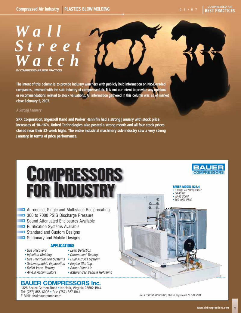
COMPRESSORSFOR INDUSTRY
• Gas Recovery
• Injection Molding
• Gas Recirculation Systems
• Seismographic Exploration
• Relief Valve Testing
• Air-Oil Accumulators
BAUER COMPRESSORS Inc.1328 Azalea Garden Road • Norfolk, Virginia 23502-1944Tel: (757) 855-6006 • Fax: (757) 857-1041E-Mail: [email protected]
APPLICATIONS
BAUER COMPRESSORS, INC. is registered to ISO 9001
• Leak Detection
• Component Testing
• Dual Air/Gas System
• Engine Starting
• Boost Plant Air
• Natural Gas Vehicle Refueling
BAUER MODEL B23.4• 3-Stage Air Compressor • 30-40 HP• 45-63 SCFM• 350-1000 PSIG
• Air-cooled, Single and Multistage Reciprocating • 300 to 7000 PSIG Discharge Pressure• Sound Attenuated Enclosures Available• Purification Systems Available• Standard and Custom Designs• Stationary and Mobile Designs
The intent of this column is to provide industry watchers with publicly held information on NYSE-tradedcompanies, involved with the sub-industry of compressed air. It is not our intent to provide any opinions or recommendations related to stock valuations. All information gathered in this column was as of marketclose February 5, 2007.
A Strong January
SPX Corporation, Ingersoll Rand and Parker Hannifin had a strong January with stock priceincreases of 10–16%. United Technologies also posted a strong month and all four stock pricesclosed near their 52-week highs. The entire industrial machinery sub-industry saw a very strongJanuary, in terms of price performance.
BY COMPRESSED AIR BEST PRACTICES
W A L L S T R E E T W A T C HBY COMPRESSED AIR BEST PRACTICES
10
BEST PRACTICES | 0 3 / 0 7 Compressed Air Industry | PLASTICS BLOW MOLDING
www.airbestpract ices.com
COMPRESSED AIR
SPX Corporation
SPX Corporation (NYSE:SPW) announced its 2007 annual financial guidance:
p Revenues are expected to increase between 9% and11% to approximately $4.7 billion. Organic revenuegrowth is expected to be 6% to 8%, while completedacquisitions and the impact of currency fluctuationsare expected to increase reported revenues byapproximately 3%.
p Earnings from continuing operations are expected toincrease to $3.80 to $3.95 per share, up 26% to 31%from the company’s 2006 full-year target. The primarydrivers of this improvement are continued strengthacross the company’s segments and a reduced tax rate.
p Free cash flow from continuing operations (cash flowfrom continuing operations less capital expenditures)is expected to increase to $240 million to $280 million.This performance represents 100% to 120% conversionof expected net income.
Chris Kearney, President and CEO said, “We are pleased to announceour expectations for 2007, including double-digit revenue, earnings andfree cash flow growth. These improvements are driven by our continuedfocus on improving SPX organically and through strategic acquisitions.”
Mr. Kearney continued, “Our internal initiatives focus on revenue growththrough innovation, new product development and expansion in emergingmarkets. Our focus on improved operating performance is centeredon expanding our lean culture and processes, and managing a well-coordinated global supply chain process. This continuous improvementmindset is allowing SPX to better serve our growing global customerbase. In addition, global demand in our key end markets remains generally strong. SPX’s strategic focus on providing solutions into globalinfrastructure development, particularly power and energy, is expectedto continue to drive growth in 2007 and beyond,” Mr. Kearney concluded.
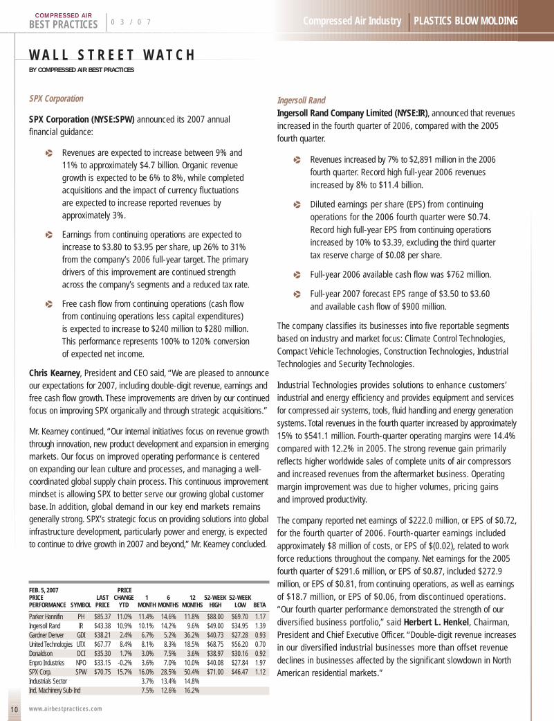
FEB. 5, 2007 PRICEPRICE LAST CHANGE 1 6 12 52-WEEK 52-WEEKPERFORMANCE SYMBOL PRICE YTD MONTH MONTHS MONTHS HIGH LOW BETA
Parker Hannifin PH $85.37 11.0% 11.4% 14.6% 11.8% $88.00 $69.70 1.17Ingersoll Rand IR $43.38 10.9% 10.1% 14.2% 9.6% $49.00 $34.95 1.39Gardner Denver GDI $38.21 2.4% 6.7% 5.2% 36.2% $40.73 $27.28 0.93United Technologies UTX $67.77 8.4% 8.1% 8.3% 18.5% $68.75 $56.20 0.70Donaldson DCI $35.30 1.7% 3.0% 7.5% 3.6% $38.97 $30.16 0.92Enpro Industries NPO $33.15 -0.2% 3.6% 7.0% 10.0% $40.08 $27.84 1.97SPX Corp. SPW $70.75 15.7% 16.0% 28.5% 50.4% $71.00 $46.47 1.12Industrials Sector 3.7% 13.4% 14.8%Ind. Machinery Sub-Ind 7.5% 12.6% 16.2%
Ingersoll RandIngersoll Rand Company Limited (NYSE:IR), announced that revenuesincreased in the fourth quarter of 2006, compared with the 2005fourth quarter.
p Revenues increased by 7% to $2,891 million in the 2006fourth quarter. Record high full-year 2006 revenuesincreased by 8% to $11.4 billion.
p Diluted earnings per share (EPS) from continuingoperations for the 2006 fourth quarter were $0.74.Record high full-year EPS from continuing operationsincreased by 10% to $3.39, excluding the third quartertax reserve charge of $0.08 per share.
p Full-year 2006 available cash flow was $762 million.
p Full-year 2007 forecast EPS range of $3.50 to $3.60and available cash flow of $900 million.
The company classifies its businesses into five reportable segmentsbased on industry and market focus: Climate Control Technologies,Compact Vehicle Technologies, Construction Technologies, IndustrialTechnologies and Security Technologies.
Industrial Technologies provides solutions to enhance customers’industrial and energy efficiency and provides equipment and servicesfor compressed air systems, tools, fluid handling and energy generationsystems. Total revenues in the fourth quarter increased by approximately15% to $541.1 million. Fourth-quarter operating margins were 14.4%compared with 12.2% in 2005. The strong revenue gain primarilyreflects higher worldwide sales of complete units of air compressorsand increased revenues from the aftermarket business. Operatingmargin improvement was due to higher volumes, pricing gains and improved productivity.
The company reported net earnings of $222.0 million, or EPS of $0.72,for the fourth quarter of 2006. Fourth-quarter earnings includedapproximately $8 million of costs, or EPS of $(0.02), related to workforce reductions throughout the company. Net earnings for the 2005fourth quarter of $291.6 million, or EPS of $0.87, included $272.9million, or EPS of $0.81, from continuing operations, as well as earningsof $18.7 million, or EPS of $0.06, from discontinued operations.“Our fourth quarter performance demonstrated the strength of ourdiversified business portfolio,” said Herbert L. Henkel, Chairman,President and Chief Executive Officer. “Double-digit revenue increasesin our diversified industrial businesses more than offset revenuedeclines in businesses affected by the significant slowdown in NorthAmerican residential markets.”

11
Compressed Air Industry | PLASTICS BLOW MOLDING 0 3 / 0 7 | BEST PRACTICESCOMPRESSED AIR
www.airbestpract ices.com
SUBSCRIBE NOW!
C O M I N G E D I T I O N S !Hospitals, Energy Management, Commercial
Printing, Food Packaging & Processing
I D E A L F O R :INDUSTRY:
Plant Engineers, Plant Managers & Maintenance Managers
MANUFACTURERS:Management, Sales, Marketing & Engineering
COMPRESSOR DISTRIBUTORS:Every Branch Location
Rates: 12-month Subscription
Number of Subscriptions 1-10 11-19 20-49 50+
U.S. $55.00 $50.00 $45.00 $40.00
Canada $65.00 $60.00 $55.00 $50.00
International $95.00 $90.00 $85.00 $80.00
3 W A Y S T O S U B S C R I B E :*
1.) Call Patricia Smith at 251-510-2598 and use your VISA/MasterCard.
2.) Email us at [email protected] mail your check.
3.) Mail your information and check to:Compressed Air Best Practices161 Clubhouse CircleFairhope, AL 36532
Checks should be made out to “Smith Onandia Communications, LLC”.Questions,call Patricia Smith:251-510-2598.
*Information required:
First Name:
Last Name:
Company Name:
Street:
City:
State (Province): Zip Code:
Country:
Phone:
Email:

W A L L S T R E E T W A T C HBY COMPRESSED AIR BEST PRACTICES
12
BEST PRACTICES | 0 3 / 0 7 Compressed Air Industry | PLASTICS BLOW MOLDING
www.airbestpract ices.com
COMPRESSED AIR
“The corrective actions we initiated in the fourth quarter to reducecosts and, where warranted, to adjust operations consistent withmarket conditions will deliver benefits throughout 2007.”
“Overall, 2006 represented the first significant challenge for the currentdiversified Ingersoll Rand business portfolio. Our record full-year revenuesand earnings per share provide clear evidence that our strategy isworking, and that our business execution remains solid.” The companycontinued to be a strong cash generator with full-year available cashflow in 2006 of $762 million.
“Based on the forecasted macro-economic environment, we anticipaterevenue growth of approximately 4% to 5% for 2007. We also expectto supplement our revenue growth with new bolt-on acquisitions.Operating margins are expected to be consistent with 2006 as highervolumes and ongoing productivity actions offset material cost inflationand investments to drive dramatic growth and operational excellence.
“Available cash flow in 2007 is anticipated to exceed $900 million.We expect to pursue internal investments that drive global organicgrowth, bolt-on acquisitions, stock buybacks and dividend enhancementsfrom the cash flow generated in 2007. We expect to invest approximatelyone billion dollars between share buybacks and acquisitions in 2007,”said Henkel. “We expect end markets and material costs in the firstquarter of 2007 to be consistent with the fourth quarter 2006.We anticipate continuing weak residential construction markets in the firstquarter, followed by a slow, gradual recovery for the balance of 2007.”
FEB. 5, 2007 5-YR COMPANY SYMBOL REVENUE 1-YR EPS 5-YR EPS RETURN ON 1-YR PERFORMANCE GROWTH GROWTH GROWTH EQUITY MARGIN PROFIT
Parker Hannifin PH 9.4% 47.6% 12.3% 19.4% 7.7%Ingersoll Rand IR 6.0% 28.9% 43.7% NA 8.0%Gardner Denver GDI 26.2% 30.9% 17.8% 16.9% 7.8%United Technologies UTX 11.4% 18.6% 14.1% 21.8% 7.3%Donaldson DCI 8.3% 13.8% 13.4% 25.1% 8.1%Enpro Industries NPO 5.1% N/A 8.7% 5.9% -1.9%SPX Corp. SPW 9.9% N/A N/A 5.4% 4.0%
Parker Hannifin
Parker Hannifin Corporation (NYSE: PH), reported second quarterfiscal year 2007 results. The company set new second quarterrecords for sales and income from continuing operations, both of which increased by double-digit percentages from a year ago.
Sales for the second quarter of fiscal-year 2007 were $2.5 billion,up 16.4 percent, as compared to sales of $2.2 billion from the sameperiod last year. Income from continuing operations in the second quarterof fiscal 2007 was $1.64 per diluted share, an increase of 53.3 percentover the $1.07 per diluted share posted in the same period a year ago.
“Led by exceptional performance in our Industrial International andAerospace segments, we were able to deliver another record secondquarter, and we remain solidly on track for another outstanding yearin fiscal 2007,” said Chairman, CEO and President Don Washkewicz.“The record results we are delivering, quarter after quarter, are beingdriven by our employees’ ongoing execution of our Win Strategy.”
Total operating margin across all segments in the second quarterwas 13.2 percent versus 11.8 percent in the same period a year ago.
p In the North American Industrial segment, second quarteroperating income increased 2.8 percent over the prioryear to $133.9 million, on sales of $959.7 million.
p In the International Industrial segment, second quarteroperating income increased 78.9 percent over theprior year to $121.8 million, on sales of $922.0 million.
p In the Aerospace segment, second quarter operatingincome increased 43.2 percent over the prior year to $67.8 million, on sales of $402.0 million.
p In the Climate & Industrial Controls segment, secondquarter operating income decreased 29.8 percent overthe prior year to $7.0 million, on sales of $227.4 million.
“Our 16.4 percent sales growth in the quarter significantly exceededour growth goal of 10 percent,” said Washkewicz. “The growth wasprofitable and balanced, with 6.4 percent derived organically,6.4 percent via acquisitions and 3.6 percent from the favorableimpact of foreign currency.”
“While we are very pleased with our overall results this quarter, specialmention must be made of our International Industrial and Aerospacesegments,” continued Washkewicz. “In the International segment, salesgrew by 36 percent and operating income increased by nearly 80 percent. Our Aerospace business also delivered excellent resultsthis quarter. Revenues grew by 16 percent and operating income by 43 percent. We expect continued strength in this segment of our business.”
“This is especially good news as International Industrial and Aerospacenow represent more than half of our total revenues,” said Washkewicz.“Particularly diligent execution of the Win Strategy in Europe is enablingus to achieve margins comparable to our North American business.”
FEB. 5, 2007 SYMBOL PRICE/ PRICE/ PRICE/ PRICE/ DIVIDEND VALUATION EARNINGS EARNINGS BOOK SALES YIELDRATIOS RATIO GROWTH RATIO RATIO RATIO
Parker-Hannifin PH 13.24 1.05 2.29 0.98 1.2%Ingersoll Rand IR 13.56 1.05 NA 1.15 1.6%Gardner Denver GDI 16.76 1.00 2.52 1.21 NAUnited Technologies UTX 18.27 1.40 3.93 1.33 1.6%Donaldson DCI 21.93 1.64 4.88 1.59 1.0%Enpro Industries NPO 22.10 1.49 1.21 0.76 NASPX Corp. SPW 28.41 1.64 2.11 0.96 1.4%
13
Compressed Air Industry | PLASTICS BLOW MOLDING 0 3 / 0 7 | BEST PRACTICESCOMPRESSED AIR
www.airbestpract ices.com
United Technologies
United Technologies Corp. (NYSE:UTX) reported fourth quarter 2006 earnings per
share of $0.87 and net income of $865 million, up 23 percent and 20 percent respectively.
Consolidated revenues for the quarter increased 14 percent to $12.8 billion, including
organic growth of 10 percent.
Full-year earnings per share of $3.71 and net income of $3.7 billion were 19 and
18 percent higher, respectively, than 2005 results. Revenues increased 12 percent
to $47.8 billion, including 9 points of organic growth, 2 points of acquisitions
and 1 point of foreign exchange.
Cash flow from operations after capital expenditures exceeded net income for both the quarter
and full year. In the fourth quarter, cash flow from operations was $1.66 billion and capital
expenditures were $351 million. For the full year, cash flow from operations was $4.80
billion and capital expenditures were $954 million. Voluntary cash contributions to pension
plans were $159 million in the fourth quarter and $190 million for the year.
“UTC had another solid year in 2006 and is set for more of the same in 2007,” said UTC
Chairman and Chief Executive Officer George David.
“Organic growth for the year was strong at 9 percent and follows 7 percent in 2005 and
8 percent in 2004. These growth rates reflect UTC’s innovative and competitive products, strong
presence in emerging markets, and good conditions in most of our markets worldwide.
The exception has been Carrier’s North American residential market over the second half
of 2006 on a substantially weaker U.S. housing market. However, robust aerospace
and commercial construction markets well more than offset this.”
“UTC also experienced production challenges in 2006 at Carrier with the launch of its high
efficiency residential air conditioning product and at Sikorsky on a doubling of volume over
the 2004–2007 period. UTC’s 19 percent growth in earnings per share for the year given
these market and production challenges demonstrates the balance in the portfolio and
the strength of UTC’s businesses overall. We believe we are well positioned for earnings
increases in 2007 and especially on favorable compares at Carrier and Sikorsky. We confirm
prior guidance for 2007 earnings per share in the $4.05 to $4.20 range and cash flow after
capital expenditures again to exceed net income,” David added.
Share repurchase in the quarter was $738 million and brought the year’s total to $2.07 billion.
Acquisition spending, including debt assumed, was $1.0 billion for the year with approximately
$514 million in the fourth quarter. Debt to capital ended the year at 31 percent.
E X P A N D I N GBY PETER RHOTEN
14
BEST PRACTICES | 0 3 / 0 7 Focus Industry | PLASTICS BLOW MOLDING
www.airbestpract ices.com
COMPRESSED AIR
This report is a summary of a compressed air system investigation our firm
conducted at a PET packaging facility in the U.S.This PET packaging facility
wanted to expand production without installing new high-pressure air compressors.
Our investigation showed the facility how to make this happen, with an ROI
of 1.5 years.The first goal of the investigation was to provide a situation analysis
of the demand side (the blow molding machines) and of the supply-side
(the high pressure and low pressure) compressed air system.The second goal
was to recommend an action plan, complete with capital cost, energy cost
and return-on-investment analysis.
All values and prices in this report were estimates based on observations made
in the plant and on our experience with PET facilities and with general compressed
air use.We were not requested to do an “audit,”entailing a more exact study utilizing
flow and kW metering technology.This would have provided exact information
of actual compressor capacities and blow molder consumption.
Situation Analysis Part I — The Blow Molding Machines
The PET packaging facility currently has 16 blow molders in production.
There are 10 Aoki and 6 Sidel units.There are plans to add at least one Aoki
and a Mag, plus a possible two additional Aoki and two Sidels units. Each molder
has a dedicated drop from the low-pressure and/or high-pressure headers.
The 12 Aoki blow molders see large pressure swings on the blow pressure.
The machines that have gauges see swings of as much as 200–300 psi.The process
engineer reported that the Aokis required 500 psi, on average, to blow the wide-
mouth bottles. In addition, the high-pressure air is reduced to 150 psi, for moving
the molds. Our experience is that 30 kg (440 psi) is usually sufficient for blowing
wide-mouth bottles.The 150 psi use may lead to higher-than-expected pressure
drops during the blow cycle.Also, the regulators may restrict flow, also leading
to the excessive pressure drops.
Of the six Sidel blow molders, four use regulators to provide the operation air
and two use plant air at 110 psi and a regulator, for an additional 120+ psi use.
The Sidel machines all see very small pressure swings, as their blow cycles
are shorter and more frequent.
P R O D U C T I O N A T A P E T
“The use of .
regulators
introduces
a 30% loss
due to valve
inefficiencies.”
15
Focus Industry | PLASTICS BLOW MOLDING 0 3 / 0 7 | BEST PRACTICESCOMPRESSED AIR
www.airbestpract ices.com
Due to the plant product mix, there are numerous mold changes that lead
to 1–3 molders being down for mold change at any time. However, in the last
few months, the facility has had occasions, when all molders are running.
During this period, the six high-pressure compressors could not keep up with
demand on a consistent basis.
This also coincided with the preventative maintenance (PM) cycle.All six Belliss
compressors go through an annual full PM and a third-stage PM every six months.
The six-month PM coincides with the plant high demand period, all molders
being up, and with hot weather.
There have been occasions where the low-pressure system has been out of air.
This appears to also have coincided with peak plant demand and hot weather.
For the high-pressure system, the number one complaint has been a lack
of pressure under full load.
There were no reports of air quality issues (water or oil in the lines).
There is a planned addition of one Aoki and one Mag in the next couple
of months, and a possibility of two more Aokis and Sidels at a later date. Further
expansion is possible.
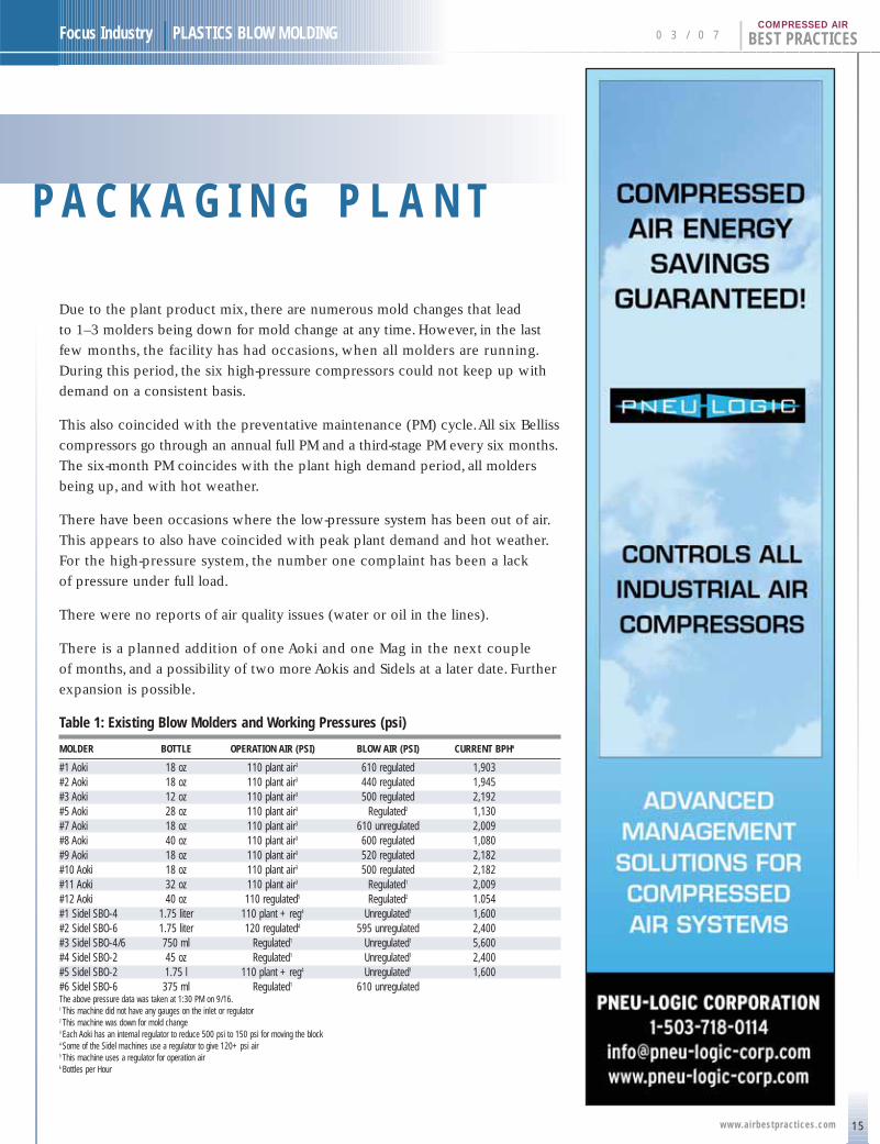
Table 1: Existing Blow Molders and Working Pressures (psi)
MOLDER BOTTLE OPERATION AIR (PSI) BLOW AIR (PSI) CURRENT BPH6
#1 Aoki 18 oz 110 plant air3 610 regulated 1,903#2 Aoki 18 oz 110 plant air3 440 regulated 1,945#3 Aoki 12 oz 110 plant air3 500 regulated 2,192#5 Aoki 28 oz 110 plant air3 Regulated2 1,130#7 Aoki 18 oz 110 plant air3 610 unregulated 2,009#8 Aoki 40 oz 110 plant air3 600 regulated 1,080#9 Aoki 18 oz 110 plant air3 520 regulated 2,182#10 Aoki 18 oz 110 plant air3 500 regulated 2,182#11 Aoki 32 oz 110 plant air3 Regulated1 2,009#12 Aoki 40 oz 110 regulated5 Regulated2 1.054#1 Sidel SBO-4 1.75 liter 110 plant + reg4 Unregulated1 1,600#2 Sidel SBO-6 1.75 liter 120 regulated4 595 unregulated 2,400#3 Sidel SBO-4/6 750 ml Regulated1 Unregulated1 5,600#4 Sidel SBO-2 45 oz Regulated1 Unregulated1 2,400#5 Sidel SBO-2 1.75 l 110 plant + reg4 Unregulated1 1,600#6 Sidel SBO-6 375 ml Regulated1 610 unregulatedThe above pressure data was taken at 1:30 PM on 9/16.1 This machine did not have any gauges on the inlet or regulator2 This machine was down for mold change3 Each Aoki has an internal regulator to reduce 500 psi to 150 psi for moving the block4 Some of the Sidel machines use a regulator to give 120+ psi air5 This machine uses a regulator for operation air6 Bottles per Hour
P A C K A G I N G P L A N T
E X P A N D I N G P R O D U C T I O N A T A P E TP A C K A G I N G P L A N T
16
BEST PRACTICES | 0 3 / 0 7 Focus Industry | PLASTICS BLOW MOLDING
www.airbestpract ices.com
COMPRESSED AIR
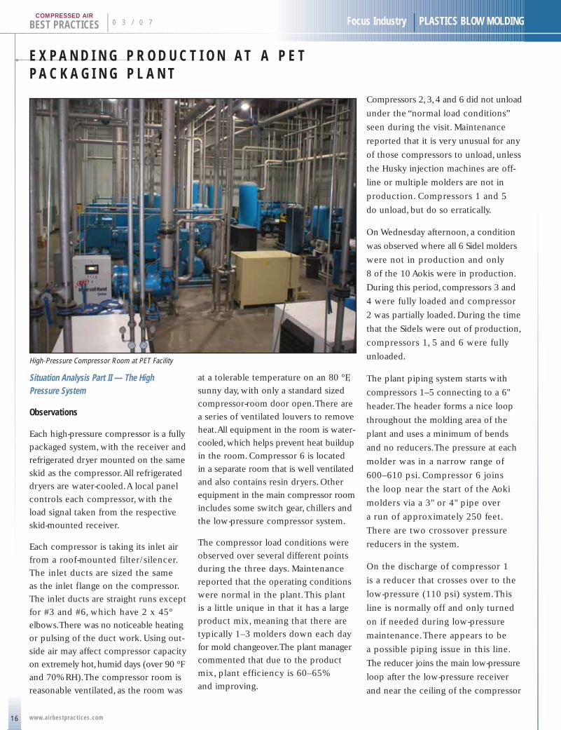
Situation Analysis Part II — The High Pressure System
Observations
Each high-pressure compressor is a fully
packaged system, with the receiver and
refrigerated dryer mounted on the same
skid as the compressor.All refrigerated
dryers are water-cooled.A local panel
controls each compressor, with the
load signal taken from the respective
skid-mounted receiver.
Each compressor is taking its inlet air
from a roof-mounted filter/silencer.
The inlet ducts are sized the same
as the inlet flange on the compressor.
The inlet ducts are straight runs except
for #3 and #6, which have 2 x 45°
elbows.There was no noticeable heating
or pulsing of the duct work. Using out-
side air may affect compressor capacity
on extremely hot,humid days (over 90 °F
and 70% RH).The compressor room is
reasonable ventilated, as the room was
at a tolerable temperature on an 80 °F,
sunny day, with only a standard sized
compressor-room door open.There are
a series of ventilated louvers to remove
heat.All equipment in the room is water-
cooled,which helps prevent heat buildup
in the room. Compressor 6 is located
in a separate room that is well ventilated
and also contains resin dryers. Other
equipment in the main compressor room
includes some switch gear, chillers and
the low-pressure compressor system.
The compressor load conditions were
observed over several different points
during the three days. Maintenance
reported that the operating conditions
were normal in the plant.This plant
is a little unique in that it has a large
product mix, meaning that there are
typically 1–3 molders down each day
for mold changeover.The plant manager
commented that due to the product
mix, plant efficiency is 60–65%
and improving.
Compressors 2,3,4 and 6 did not unload
under the “normal load conditions”
seen during the visit. Maintenance
reported that it is very unusual for any
of those compressors to unload, unless
the Husky injection machines are off-
line or multiple molders are not in
production. Compressors 1 and 5
do unload, but do so erratically.
On Wednesday afternoon, a condition
was observed where all 6 Sidel molders
were not in production and only
8 of the 10 Aokis were in production.
During this period, compressors 3 and
4 were fully loaded and compressor
2 was partially loaded. During the time
that the Sidels were out of production,
compressors 1, 5 and 6 were fully
unloaded.
The plant piping system starts with
compressors 1–5 connecting to a 6"
header.The header forms a nice loop
throughout the molding area of the
plant and uses a minimum of bends
and no reducers.The pressure at each
molder was in a narrow range of
600–610 psi. Compressor 6 joins
the loop near the start of the Aoki
molders via a 3" or 4" pipe over
a run of approximately 250 feet.
There are two crossover pressure
reducers in the system.
On the discharge of compressor 1
is a reducer that crosses over to the
low-pressure (110 psi) system.This
line is normally off and only turned
on if needed during low-pressure
maintenance.There appears to be
a possible piping issue in this line.
The reducer joins the main low-pressure
loop after the low-pressure receiver
and near the ceiling of the compressor
High-Pressure Compressor Room at PET Facility
Focus Industry | PLASTICS BLOW MOLDING 0 3 / 0 7 | BEST PRACTICESCOMPRESSED AIR
room.With the piping arranged as it is,
condensate from the system can gather
in this pipe and there is no automatic
drain in the run. Maintenance has
reported a water issue in the low-
pressure system,when this line is used —
indicating that condensate does gather
in the run. It may be better to take this
run into the low-pressure receiver to
avoid condensate buildup in the pipe
run. Off of compressor 6 is a reducer
to 150 psi dedicated to the Husky
injection machines.There have been
no problems reported with this line.
There is a lack of usable compressed air
storage in the system. Each compressor
has a local 240-gallon tank providing
1,440 gallons of storage. However,
being divided before the header, the
storage has little impact on enabling
the compressors to unload.The header
and loop provide a nice pressure balance
in the system, but additional storage
in or near the compressor room would
allow the compressors to unload and
rotate, using the existing sequencing
panel.A general rule for adequate storage
is 1 gallon per cfm of capacity.
This would mean the system should
have about 5,000 gallons of storage.
Adequate storage would enable the
compressors to unload.Proper unloading
and rotating of the compressors
reduces wear, leading to reduced
maintenance costs.
There is a central sequencing control
system, but it is not being used.
The sequencing panel was used at one
time, but during extended unloaded
time, the compressors would shut
down.When demand increased, the
compressors would take too long
to ramp up and the system pressure
would drop low enough to shut down
molders on alarm. If the sequence
panel is to be used, there must be
adequate central storage and the
compressor panels modified to enable
a longer unloaded run time before shut
down, or to not shut down at all.
Compressor 6 feeds a dedicated 150 psi
line to the Husky equipment via a
pressure reducer. Compressor 6 rarely
unloads. Maintenance reported that
compressor 6 does tend to unload
when the Huskies are out of production.
As noted, only compressors 1 and 5 see
any consistent unloading. Compressors
1–5 are in line in the compressor room
such that compressor 1 is near the Sidel
end of the loop and compressor 5 is
near the Aoki end of the loop.As pressure
builds in the system, compressors
1 and 5 see the rise first and unload.
Actual settings on the pressure switches
may also affect which compressors
unload in which sequence.
During full plant production, there
is no high-pressure compressor back-up
capacity.All six compressors are
required to meet demand. During July
and August, the plant had to shut down
various molders because the compressors
could not keep up during full produc-
tion due to the hot days and the
machines being near the end of their
PM cycle.
© 2007 UE Systems, Inc.
Email: [email protected] • www.uesystems.com 14 Hayes St., Elmsford, NY 10523-2536 USA
1-800-223-1325
COMPRESSED AIR ISN’T FREECOMPRESSED AIR ISN’T FREE Here’s a way to Save Energy Dollars
& Find Leaks Efficiently !
Here’s a way to Save Energy Dollars & Find Leaks Efficiently !
THE ULTRAPROBE 10,000ULTRASONIC INSPECTION SYSTEM…
THE ULTRAPROBE ® 10,000ULTRASONIC INSPECTION SYSTEM…
Come join us at Ultrasound World IV • January 27-30, 2008 • Clearwater Beach, FL
Cut Energy Waste Now! Compressed air is the most costly utility in
plants today. The Ultraprobe system helps you find leaks, plus record
sounds, record data, calculate and report your savings.
Call or Email for more information & your FREE Compressed Air Guide.
17www.airbestpract ices.com
E X P A N D I N G P R O D U C T I O N A T A P E TP A C K A G I N G P L A N T
18
BEST PRACTICES | 0 3 / 0 7 Focus Industry | PLASTICS BLOW MOLDING
www.airbestpract ices.com
COMPRESSED AIR
Table 2: The High-Pressure Compressor System
COMPRESSOR: WH28H3N (#1) WH28H3N (#2) WH28H3N (#3)
Make: Belliss & Morcom Belliss & Morcom Belliss & MorcomMotor Horsepower: 300 300 300Motor RPM: 1,175 (belt) 1,175 (belt) 1,175 (belt)Motor FLA: 361 361 361Capacity: 730 cfm at 650 psi 730 cfm at 650 psi 730 cfm at 650 psiCompressor hours: 150,465 133,308 75,223Loaded hours: Unreliable Unreliable UnreliableCondition: Good Good GoodCoolers: Good, running cool Good, A/C a bit warm Good, running coolReceiver: 240 gal (on skid) 240 gal (on skid) 240 gal (on skid)Dryer: Hankison 80500 Hankison 80500 Hankison HPRD-3Dryer condition: Good Good GoodDrains: Timed-electric, Timed-electric, Timed-electric,
central control central control central control
COMPRESSOR: WH40H3N (#4) WH28H3N (#5) WH40H3N (#6)
Make: Belliss & Morcom Belliss & Morcom Belliss & MorcomMotor Horsepower: 500 300 500Motor RPM: 1,175 (belt) 1,175 (belt) 1,175 (belt)Motor FLA: 567 361 569Capacity: 1,100 cfm at 650 psi 730 cfm at 650 psi 1,100 cfm at 650 psiCompressor hours: 75,309 38,077 72,319 Loaded hours: Unreliable Unreliable UnreliableCondition: Good Good GoodCoolers: Good, running cool Good, running cool Good, running coolReceiver: 240 gal (on skid) 240 gal (on skid) 240 gal (on skid)Dryer: Hankison HPRD-4 Zurn R-150W-7.5 Hankison HPRD-4Dryer condition: Good Good GoodDrains: Timed-electric, Timed-electric, Timed-electric,
central control central control central control
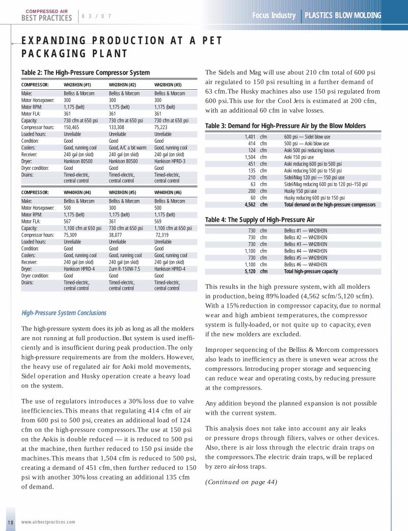
High-Pressure System Conclusions
The high-pressure system does its job as long as all the molders
are not running at full production. But system is used ineffi-
ciently and is insufficient during peak production.The only
high-pressure requirements are from the molders. However,
the heavy use of regulated air for Aoki mold movements,
Sidel operation and Husky operation create a heavy load
on the system.
The use of regulators introduces a 30% loss due to valve
inefficiencies.This means that regulating 414 cfm of air
from 600 psi to 500 psi, creates an additional load of 124
cfm on the high-pressure compressors.The use at 150 psi
on the Aokis is double reduced — it is reduced to 500 psi
at the machine, then further reduced to 150 psi inside the
machines.This means that 1,504 cfm is reduced to 500 psi,
creating a demand of 451 cfm, then further reduced to 150
psi with another 30% loss creating an additional 135 cfm
of demand.
The Sidels and Mag will use about 210 cfm total of 600 psi
air regulated to 150 psi resulting in a further demand of
63 cfm.The Husky machines also use 150 psi regulated from
600 psi.This use for the Cool Jets is estimated at 200 cfm,
with an additional 60 cfm in valve losses.
Table 3: Demand for High-Pressure Air by the Blow Molders
1,401 cfm 600 psi — Sidel blow use414 cfm 500 psi — Aoki blow use124 cfm Aoki 500 psi reducing losses
1,504 cfm Aoki 150 psi use451 cfm Aoki reducing 600 psi to 500 psi135 cfm Aoki reducing 500 psi to 150 psi210 cfm Sidel/Mag 120 psi — 150 psi use63 cfm Sidel/Mag reducing 600 psi to 120 psi–150 psi
200 cfm Husky 150 psi use60 cfm Husky reducing 600 psi to 150 psi
4,562 cfm Total demand on the high-pressure compressors
Table 4: The Supply of High-Pressure Air
730 cfm Belliss #1 — WH28H3N730 cfm Belliss #2 — WH28H3N730 cfm Belliss #3 — WH28H3N
1,100 cfm Belliss #4 — WH40H3N730 cfm Belliss #5 — WH28H3N
1,100 cfm Belliss #6 — WH40H3N5,120 cfm Total high-pressure capacity
This results in the high pressure system, with all molders
in production, being 89% loaded (4,562 scfm/5,120 scfm).
With a 15% reduction in compressor capacity, due to normal
wear and high ambient temperatures, the compressor
system is fully-loaded, or not quite up to capacity, even
if the new molders are excluded.
Improper sequencing of the Belliss & Morcom compressors
also leads to inefficiency as there is uneven wear across the
compressors. Introducing proper storage and sequencing
can reduce wear and operating costs, by reducing pressure
at the compressors.
Any addition beyond the planned expansion is not possible
with the current system.
This analysis does not take into account any air leaks
or pressure drops through filters, valves or other devices.
Also, there is air loss through the electric drain traps on
the compressors.The electric drain traps, will be replaced
by zero air-loss traps.
(Continued on page 44)
Focus Industry | PLASTICS BLOW MOLDING 0 3 / 0 7 | BEST PRACTICESCOMPRESSED AIR
C e n t r a l C o o l i n g S y s t e m f o r N e w P E T A i r C o m p r e s s o r s BY GRAHAM WHITMORE
The Pepsi bottling plant in Harrisburg, PA was expanded in 2006, with the addition
of a new PET bottling line for Pepsi’s Aquafina bottled water.
The entire automated production line includes the PET bottle-molding facility and
water filtration plant, water-cooled air compressors and a water-cooled atmospheric
dehumidification plant.Atmospheric dehumidification is especially important in
PET production to avoid condensation on the (chilled water-cooled) molds, during
the summer production when humidity is high.
The primary air compressor is a water-cooled, oil-free, rotary machine, followed
by a desiccant dryer, which supplies oil-free air with a dew point around -20 ºF.
This is immediately followed by an oil-free, horizontally opposed, piston booster
compressor, which supplies 600 psig air pressure to the PET blow molder.
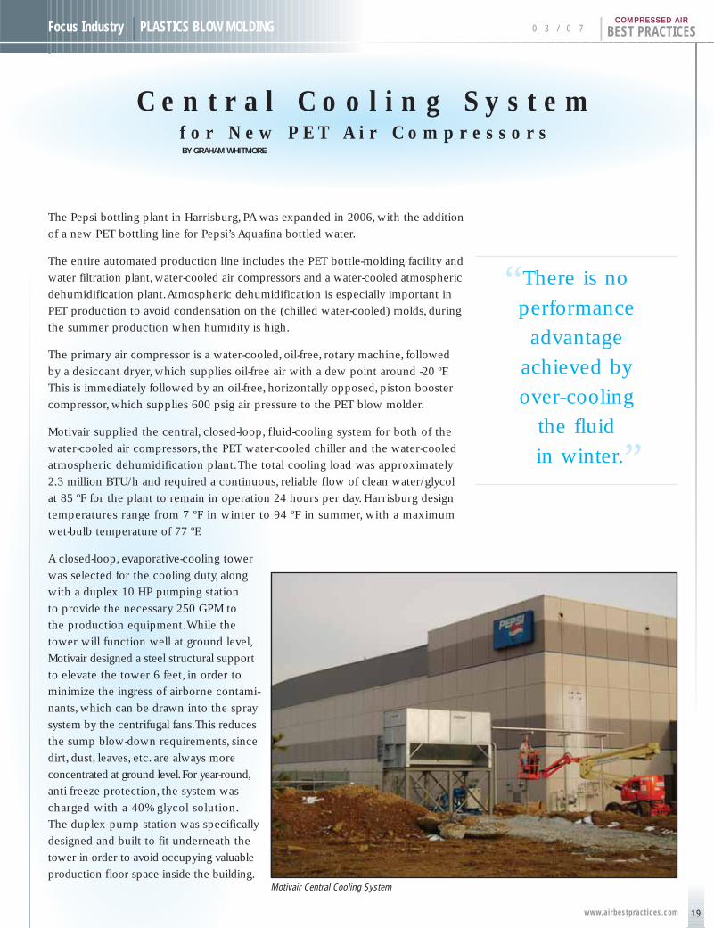
Motivair supplied the central, closed-loop, fluid-cooling system for both of the
water-cooled air compressors, the PET water-cooled chiller and the water-cooled
atmospheric dehumidification plant.The total cooling load was approximately
2.3 million BTU/h and required a continuous, reliable flow of clean water/glycol
at 85 ºF for the plant to remain in operation 24 hours per day. Harrisburg design
temperatures range from 7 ºF in winter to 94 ºF in summer, with a maximum
wet-bulb temperature of 77 ºF.
A closed-loop, evaporative-cooling tower
was selected for the cooling duty, along
with a duplex 10 HP pumping station
to provide the necessary 250 GPM to
the production equipment.While the
tower will function well at ground level,
Motivair designed a steel structural support
to elevate the tower 6 feet, in order to
minimize the ingress of airborne contami-
nants, which can be drawn into the spray
system by the centrifugal fans.This reduces
the sump blow-down requirements, since
dirt, dust, leaves, etc. are always more
concentrated at ground level.For year-round,
anti-freeze protection, the system was
charged with a 40% glycol solution.
The duplex pump station was specifically
designed and built to fit underneath the
tower in order to avoid occupying valuable
production floor space inside the building.Motivair Central Cooling System
“There is no .
performance
advantage
achieved by
over-cooling
the fluid
in winter.”
19www.airbestpract ices.com

C E N T R A L C O O L I N G S Y S T E M F O R N E WP E T A I R C O M P R E S S O R S
20
BEST PRACTICES | 0 3 / 0 7 Focus Industry | PLASTICS BLOW MOLDING
www.airbestpract ices.com
COMPRESSED AIR
Closed-loop, evaporative-cooling is especially suitable for
this application. It offers a close approach to the prevailing
wet bulb temperature, while the circulating cooling fluid is
never exposed to the ambient air or the spray water.Therefore
the cooling fluid inside the equipment is always clean, while
water-cooled equipment maintenance is virtually eliminated.
The only water treatment required is for the spray makeup
water to replace that lost by evaporation.This makeup
is approximately 2 GPM per million BTU/h, or 4.1 GPM
in the maximum summer design operating conditions.
An energy-saving feature was the addition of automatic cycling
controls for the fan motor and spray pump during lower winter
temperatures.There is no performance advantage achieved
by over-cooling the fluid in winter.Therefore at approximately
60 ºF leaving fluid temperature, the fan motor is stopped to
conserve energy, while the spray pump continues to operate.
At 50 ºF leaving fluid temperature, the spray pump is also
stopped.The adjustable control differential is set sufficiently
wide to prevent short-cycling of the fan or pump during
winter operation.
The duplex pump station is designed for automatic operation
and is electrically connected with the closed loop tower in
a common NEMA 4 control panel with interlocked disconnect
switch. In the event of a pump malfunction, the alarm is set
and the standby pump starts automatically. Pump isolation
and check valves, gauges, expansion tank, flow, level and
temperature alarms complete the factory-built package.
An ASME pressure relief valve ensures equipment and
personnel safety in the event there is ever a high-pressure
compressed air leak into the cooling system.
Following the success of the Harrisburg central cooling
system, similar Motivair cooling packages were installed
at the Pepsi bottling plants in Houston,Tampa and Calgary.
For more information, please contact Mr. Graham Whitmore, MotivairCorporation, email: [email protected], tel: 716-689-0222,www.motivaircorp.com
0 3 / 0 7 | BEST PRACTICESCOMPRESSED AIR
G R E E NT H E I N I T I A T I V E S A T
P A C E I N D U S T R I E S
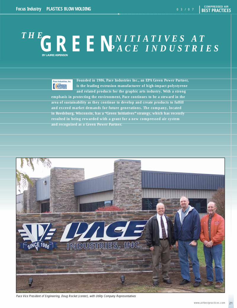
Founded in 1986, Pace Industries Inc., an EPA Green Power Partner,
is the leading extrusion manufacturer of high-impact polystyrene
and related products for the graphic arts industry. With a strong
emphasis in protecting the environment, Pace continues to be a steward in the
area of sustainability as they continue to develop and create products to fulfill
and exceed market demands for future generations. The company, located
in Reedsburg, Wisconsin, has a “Green Initiatives” strategy, which has recently
resulted in being rewarded with a grant for a new compressed air system
and recognized as a Green Power Partner.
Pace Vice President of Engineering, Doug Rocket (center), with Utility Company Representatives
21www.airbestpract ices.com
Focus Industry | PLASTICS BLOW MOLDING
BY LAURIE ASPENSON
T H E G R E E N I N I T I A T I V E S A T P A C E I N D U S T R I E S
22
BEST PRACTICES | 0 3 / 0 7 Focus Industry | PLASTICS BLOW MOLDING
www.airbestpract ices.com
COMPRESSED AIR
Grant Awarded by Wisconsin Public Power
Pace Industries was awarded a grant from Wisconsin Public
Power, Inc. (WPPI), the energy supplier for Reedsburg Utility
Commission.WPPI’s “RFP for Energy Efficiency” program
was open to large commercial, industrial and institutional
utility customers consuming significant amounts of power.
The goal of the program was to help users reduce energy
consumption through upgrades to equipment and systems
within their current facilities.
Through the RFP program, large commercial customers
served by WPPI member utilities were invited to submit
competitive bids for funding to make energy-saving
improvements.To be considered for incentive funding,
customer bids were required to demonstrate a resulting
reduction in electrical demand of at least 50 kilowatts during
periods of peak energy use.WPPI outlined minimum efficiency
requirements for any proposed equipment, and required
grant applications to include an external audit,demonstrating
current energy consumption, proposed equipment and
system changes, and the investment required to meet
the energy efficiency goals of WPPI’s program.
In review of the WPPI program and in keeping with their
“Green Initiatives,”Pace felt that the plant’s compressed air
system was an area that could be improved.The plant uses
large quantities of air in many of its manufacturing systems.
“We had recently contracted with Industrial Energy Solutions
to complete a compressed air audit. Recommendations of
the audit showed that the plant compressed air system was
inefficient by today’s standards and would require a larger
investment.Timing couldn’t be better as I had just received
WPPI’s announcement that they were accepting requests
to assist in energy efficiency funding,” stated Doug Rocket,
Pace’s VP of Engineering & Facility. Rockett continued,“WPPI’s
representative Jim Schieble was instrumental in helping tie
together our project goals with our collected data.The end
result was Pace being awarded $51,000.00 to assist in
a project that will exceed $100,000.00 in total costs.”
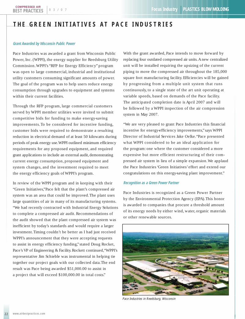
With the grant awarded, Pace intends to move forward by
replacing four outdated compressed air units.A new centralized
unit will be installed requiring the upsizing of the current
piping to move the compressed air throughout the 185,000
square foot manufacturing facility. Efficiencies will be gained
by progressing from a multiple unit system that runs
continuously, to a single state of the art unit operating at
variable speeds, based on demands of the Pace facility.
The anticipated completion date is April 2007 and will
be followed by a WPPI inspection of the air compression
system in May 2007.
“We are very pleased to grant Pace Industries this financial
incentive for energy-efficiency improvements,” says WPPI
Director of Industrial Services Jake Oelke.“Pace presented
what WPPI considered to be an ideal application for
the program: one where the customer considered a more
expensive but more efficient restructuring of their com-
pressed air system in lieu of a simple expansion.We applaud
the Pace Industries ‘Green Initiatives’ effort and extend our
congratulations on this energy-saving plant improvement.”
Recognition as a Green Power Partner
Pace Industries is recognized as a Green Power Partner
by the Environmental Protection Agency (EPA).This honor
is awarded to companies that procure a threshold amount
of its energy needs by either wind, water, organic materials
or other renewable sources.
Pace Industries in Reedsburg, Wisconsin
Focus Industry | PLASTICS BLOW MOLDING 0 3 / 0 7 | BEST PRACTICESCOMPRESSED AIR
Pace Industries’ manufacturing facility,
located in Reedsburg,Wisconsin, has
secured a percentage of WPPI’s wind
turbine power as an alternative energy
source instead of the traditional products
used such as coal, oil or natural gas.
“Right out of the gate, the wind power
we are purchasing is the equivalent
to 22 tons of coal-generated power.
This translates to the amount of power
consumed by 52 homes, annually,”
states Blake Pace, president of Pace
Industries.“Pace’s green power initiatives
have an impact on preserving fossil fuels
for future generations and hopefully
setting a course for other businesses
in selecting alternative natural resources.”
Pace Industries’ recent recognition
as a Green Power Partner complements
a corporate culture that focuses on
reducing,re-using and recycling products
and services for the well-being of
employees, customers and environment.
Some of the green power initiatives
include:
THE CONDENSATE MANAGEMENT SPECIALISTS
JORC offers a product range that covers ALL condensaterequirements. We provide total quality and reliability sothat you don’t have to compromise—our range of versatileand cost-effective solutions are designed to meet all ofyour condensate management needs. Through continuedinvestment in research and development, we offer up-to-datesolutions that you can count on.
At JORC we never compromise on Quality or Reliability—why should you?
Contact us today:JORC Industrial LLC.
1146 River Road • New Castle, DE 19720Phone: 302-395-0310 • Fax: 302-395-0312
E-mail: [email protected]
See our new online catalog atwww.jorc.com
MotorizedBall Valves
Magnetic ZeroAir Loss Drains
Electronic ZeroAir Loss Drains
TimerDrains
Compressed AirLeak Detector
Oil WaterSeparators
23www.airbestpract ices.com
1. Pace Industries continues to explore new bio-basedpolymers that incorporate agricultural productssuch as corn or soy beans as alternatives to fossilfuel-based resins.
2. Pace’s PS-Absolve is a new engineered polystyrenethat looks, feels and processes likes standardstyrene but incorporates state-of-art polymertechnology, certified by a raw material supplier,to facilitate degradation in litter form, commercialor residential compost as well as in landfill disposal.
3. Customer Recycling Programs offer customers theopportunity to return packaging materials as wellas plastic scrap. In order to encourage recycling,an inflated value is offered for these materials.These programs eliminate the potential landfill of at least 2 to 3 million pounds of waste annually.
4. Neighborhood Electric Vehicles (NEV) feature zero emissions for indoor/outdoor operations and can travel 200 miles for the cost of one gallonof gas. Legalized for road use by the Reedsburgcommunity, Pace Industries was the first manu-facturer to purchase an NEV for company travelwithin the cities’ limits.
5. Pace provides ongoing Employee Education relatedto recycling and renewable energy options.As a result of the education, employees areencouraged to participate in minimizing environ-mental impact at both work and at home.
For more information regarding Pace Industries’ Green Initiatives, please e-mailrequests to administrator at [email protected] or contact LaurieAspenson at tel: 608-524-6777, ext. 323.

Give your business a solid shot of ideas, machinery and equipment,
technologies and trends, and global networking opportunities. Learn
about new applications and process improvement at WESTEC’s new
Plant Tours & Sessions. It’s all at WESTEC 2007, the primary
resource for West Coast manufacturers. Discover strategies for
streamlining your operations, improving product quality, and competing
vigorously in world markets. Transact serious business on the show
floor. Network with industry leaders at the SME International Awards
Gala. Don’t miss WESTEC 2007. One solid event.
March 26-29, 2007Los Angeles Convention Center
Los Angeles, California
For more information visit www.sme.org/westec. Or call 800.733.4763.The Total Manufacturing Experience

Focus Industry | PLASTICS BLOW MOLDING
E N E R G Y - E F F I C I E N T A I R N O Z Z L E Sf o r t h e B l o w M o l d i n g I n d u s t r yBY HANK VAN ORMER
0 3 / 0 7 | BEST PRACTICESCOMPRESSED AIR
As in many industries, most plastic injection molding plants
use a great deal of compressed air in “blowing off” the product.
It is used to remove cleaning agents and water, to move
product along the line and to remove rejected pieces.
The compressed air used in the operations varies from open-
tube or pipe-blowing, to quality non-amplifying control and/or
dispersion nozzles, to venturi-driven amplifying nozzles.
Almost without exception, any “straight” compressed air
blow-off, through an open pipe or tube,will be very inefficient
and the compressed air used can be reduced by 50% or more.
Two Types of Efficiency Nozzles — Control/Dispersions and Venturi Amplifiers
The open-pipe flows compressed air to the process with
very little, if any, amplification.Turbulent compressed air
blasts straight out of the pipe or tube. It not only wastes
compressed air, but also violates OSHA noise and dead-ended
pressure requirements.There are two basic types of efficiency
nozzles: dispersion and venturi amplifiers.
Applying a high-quality non-amplifying dispersion nozzle will
reduce this air usage significantly and it will control the air
flow.We now have a predictable, repeatable air flow, which
when implemented correctly, will be more effective in
removal due to a potential optimum blow profile.Applied
with properly selected regulators, the compressed air inlet
pressure can be adjusted to identify the optimum flow
at the lowest effective inlet pressure.
Regardless of application, there are several guidelines that
should always be applied to compressed air being used for
open blow off:
p Use high pressure only as a last resort
p All blow-off air should be regulated to the lowesteffective pressure — higher pressure means higherflow, which may not be needed
p Use venturi air amplifier nozzles whenever and whereverpossible — this will usually reduce blow-off air by atleast 50%, freeing up more air flow for other applications
p All blow-off air should be controlled to shut off (automatically) when not needed for production.
Plants with many 1⁄8" and 1⁄4" open lines running as blow
off on units will use approximately 14 and 32 cfm each,
respectively, at 80 psig
Another type of nozzle to use is an air amplifier,which requires
less compressed air than a non-amplifying nozzle and flows
more total air volume at the process with somewhat less
thrust.Air amplifiers use “venturi” action to pull in significant
amounts of ambient air and mix it directly into the air stream,
which amplifies the amount of air available at the point of use.
Air amplifiers have amplification ratios up to 25:1. By reducing
a 32–cfm demand to 10 cfm of compressed air, they can supply
up to 250 cfm of blow-off air to the process and generate
a savings of 22 cfm of compressed air per 1⁄4" blow off.
25www.airbestpract ices.com
E N E R G Y - E F F I C I E N T A I R N O Z Z L E S F O R T H E B L O W M O L D I N G I N D U S T R Y
BEST PRACTICES | 0 3 / 0 7 Focus Industry | PLASTICS BLOW MOLDINGCOMPRESSED AIR
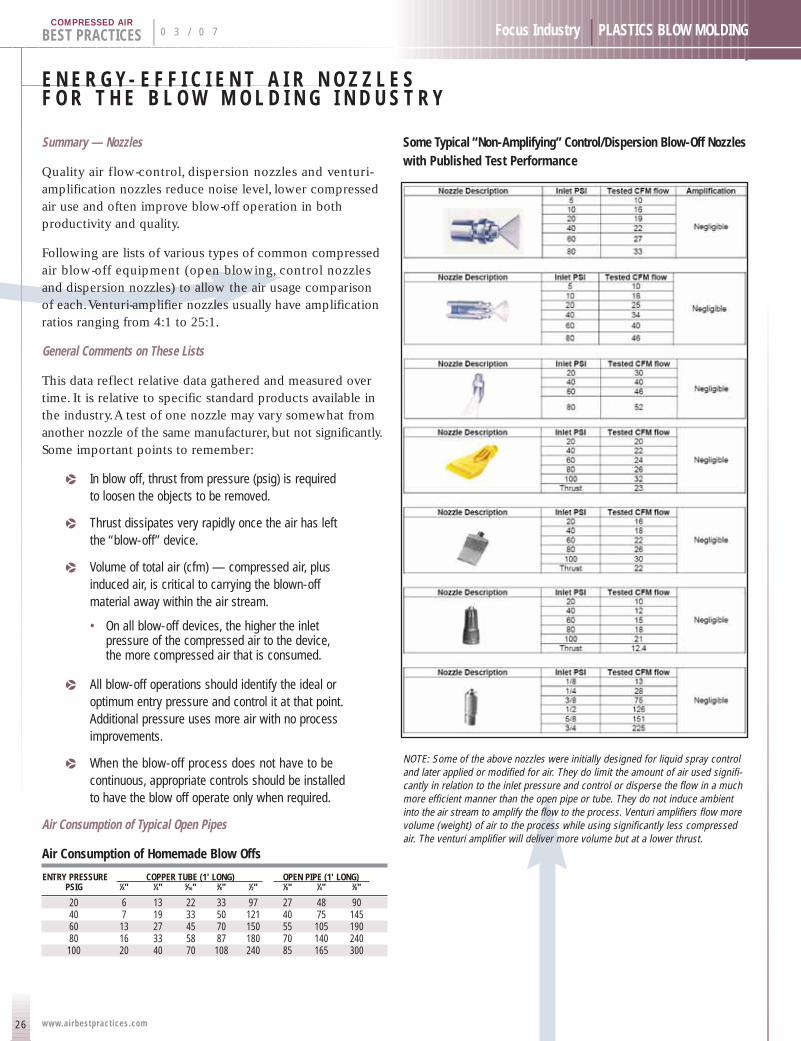
Summary — Nozzles
Quality air flow-control, dispersion nozzles and venturi-amplification nozzles reduce noise level, lower compressedair use and often improve blow-off operation in both productivity and quality.
Following are lists of various types of common compressedair blow-off equipment (open blowing, control nozzles and dispersion nozzles) to allow the air usage comparisonof each.Venturi-amplifier nozzles usually have amplificationratios ranging from 4:1 to 25:1.
General Comments on These Lists
This data reflect relative data gathered and measured overtime. It is relative to specific standard products available inthe industry.A test of one nozzle may vary somewhat fromanother nozzle of the same manufacturer, but not significantly.Some important points to remember:
p In blow off, thrust from pressure (psig) is required to loosen the objects to be removed.
p Thrust dissipates very rapidly once the air has left the “blow-off” device.
p Volume of total air (cfm) — compressed air, plusinduced air, is critical to carrying the blown-off material away within the air stream.
• On all blow-off devices, the higher the inletpressure of the compressed air to the device,the more compressed air that is consumed.
p All blow-off operations should identify the ideal oroptimum entry pressure and control it at that point.Additional pressure uses more air with no processimprovements.
p When the blow-off process does not have to be continuous, appropriate controls should be installed to have the blow off operate only when required.
Air Consumption of Typical Open Pipes
Air Consumption of Homemade Blow Offs
ENTRY PRESSURE COPPER TUBE (1' LONG) OPEN PIPE (1' LONG)PSIG 1⁄8" 1⁄4" 5⁄16" 3⁄8" 1⁄2" 1⁄8" 1⁄4" 3⁄8"
20 6 13 22 33 97 27 48 9040 7 19 33 50 121 40 75 14560 13 27 45 70 150 55 105 19080 16 33 58 87 180 70 140 240
100 20 40 70 108 240 85 165 300
Some Typical “Non-Amplifying” Control/Dispersion Blow-Off Nozzleswith Published Test Performance
NOTE: Some of the above nozzles were initially designed for liquid spray controland later applied or modified for air. They do limit the amount of air used signifi-cantly in relation to the inlet pressure and control or disperse the flow in a muchmore efficient manner than the open pipe or tube. They do not induce ambientinto the air stream to amplify the flow to the process. Venturi amplifiers flow morevolume (weight) of air to the process while using significantly less compressedair. The venturi amplifier will deliver more volume but at a lower thrust.
26 www.airbestpract ices.com
27
Focus Industry | PLASTICS BLOW MOLDING 0 3 / 0 7 | BEST PRACTICESCOMPRESSED AIR
www.airbestpract ices.com
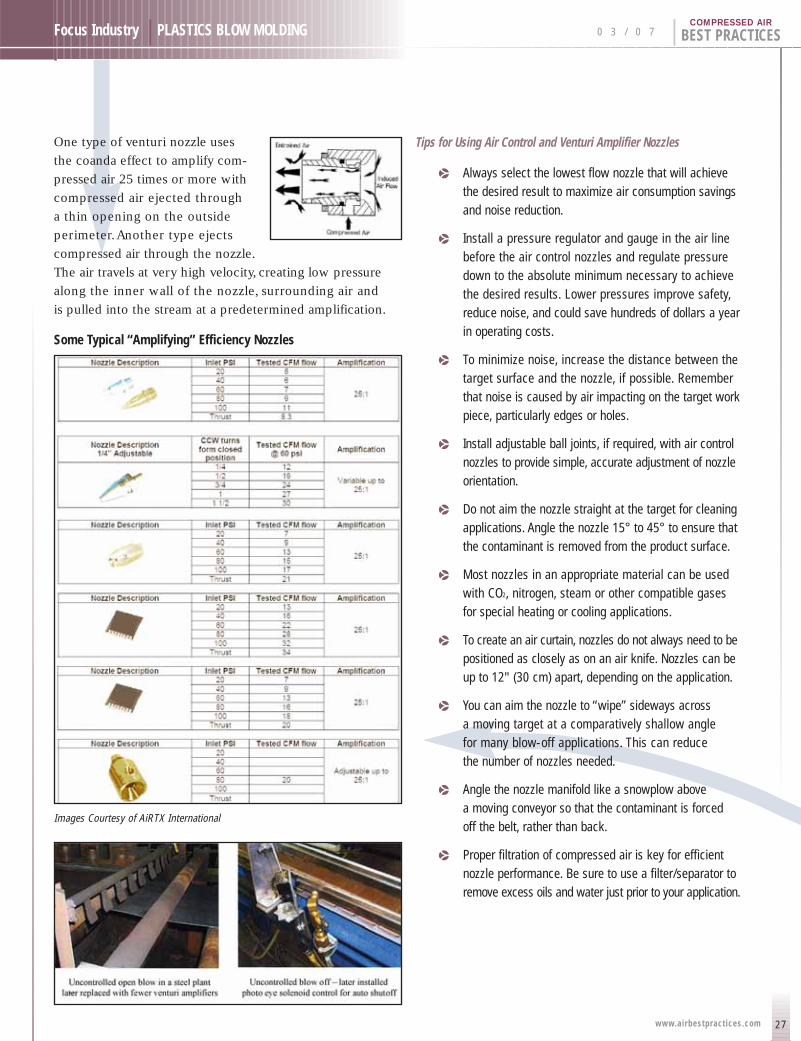
One type of venturi nozzle uses
the coanda effect to amplify com-
pressed air 25 times or more with
compressed air ejected through
a thin opening on the outside
perimeter.Another type ejects
compressed air through the nozzle.
The air travels at very high velocity, creating low pressure
along the inner wall of the nozzle, surrounding air and
is pulled into the stream at a predetermined amplification.
Some Typical “Amplifying” Efficiency Nozzles
Images Courtesy of AiRTX International
Tips for Using Air Control and Venturi Amplifier Nozzles
p Always select the lowest flow nozzle that will achievethe desired result to maximize air consumption savingsand noise reduction.
p Install a pressure regulator and gauge in the air linebefore the air control nozzles and regulate pressuredown to the absolute minimum necessary to achievethe desired results. Lower pressures improve safety,reduce noise, and could save hundreds of dollars a yearin operating costs.
p To minimize noise, increase the distance between thetarget surface and the nozzle, if possible. Rememberthat noise is caused by air impacting on the target workpiece, particularly edges or holes.
p Install adjustable ball joints, if required, with air controlnozzles to provide simple, accurate adjustment of nozzleorientation.
p Do not aim the nozzle straight at the target for cleaningapplications. Angle the nozzle 15° to 45° to ensure thatthe contaminant is removed from the product surface.
p Most nozzles in an appropriate material can be usedwith CO2, nitrogen, steam or other compatible gases for special heating or cooling applications.
p To create an air curtain, nozzles do not always need to bepositioned as closely as on an air knife. Nozzles can beup to 12" (30 cm) apart, depending on the application.
p You can aim the nozzle to “wipe” sideways across a moving target at a comparatively shallow angle for many blow-off applications. This can reduce the number of nozzles needed.
p Angle the nozzle manifold like a snowplow above a moving conveyor so that the contaminant is forced off the belt, rather than back.
p Proper filtration of compressed air is key for efficientnozzle performance. Be sure to use a filter/separator toremove excess oils and water just prior to your application.
28
BEST PRACTICES | 0 3 / 0 7 Focus Industry | PLASTICS BLOW MOLDING
www.airbestpract ices.com
COMPRESSED AIR
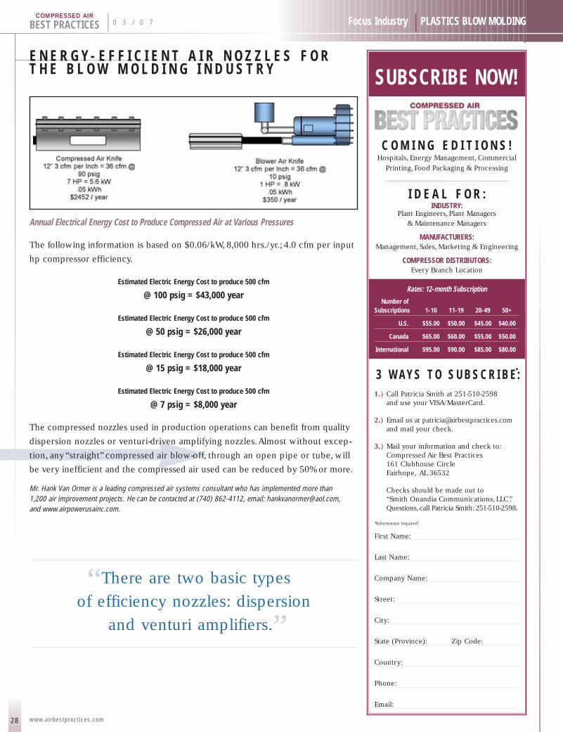
Annual Electrical Energy Cost to Produce Compressed Air at Various Pressures
The following information is based on $0.06/kW, 8,000 hrs./yr.; 4.0 cfm per input
hp compressor efficiency.
Estimated Electric Energy Cost to produce 500 cfm
@ 100 psig = $43,000 year
Estimated Electric Energy Cost to produce 500 cfm
@ 50 psig = $26,000 year
Estimated Electric Energy Cost to produce 500 cfm
@ 15 psig = $18,000 year
Estimated Electric Energy Cost to produce 500 cfm
@ 7 psig = $8,000 year
The compressed nozzles used in production operations can benefit from quality
dispersion nozzles or venturi-driven amplifying nozzles.Almost without excep-
tion, any “straight” compressed air blow-off, through an open pipe or tube, will
be very inefficient and the compressed air used can be reduced by 50% or more.
Mr. Hank Van Ormer is a leading compressed air systems consultant who has implemented more than 1,200 air improvement projects. He can be contacted at (740) 862-4112, email: [email protected], and www.airpowerusainc.com.
E N E R G Y - E F F I C I E N T A I R N O Z Z L E S F O RT H E B L O W M O L D I N G I N D U S T R Y
“There are two basic types .
of efficiency nozzles: dispersion
and venturi amplifiers.”
SUBSCRIBE NOW!
C O M I N G E D I T I O N S !Hospitals, Energy Management, Commercial
Printing, Food Packaging & Processing
I D E A L F O R :INDUSTRY:
Plant Engineers, Plant Managers & Maintenance Managers
MANUFACTURERS:Management, Sales, Marketing & Engineering
COMPRESSOR DISTRIBUTORS:Every Branch Location
Rates: 12-month Subscription
Number of Subscriptions 1-10 11-19 20-49 50+
U.S. $55.00 $50.00 $45.00 $40.00
Canada $65.00 $60.00 $55.00 $50.00
International $95.00 $90.00 $85.00 $80.00
3 W A Y S T O S U B S C R I B E :*
1.) Call Patricia Smith at 251-510-2598 and use your VISA/MasterCard.
2.) Email us at [email protected] mail your check.
3.) Mail your information and check to:Compressed Air Best Practices161 Clubhouse CircleFairhope, AL 36532
Checks should be made out to “Smith Onandia Communications, LLC”.Questions,call Patricia Smith:251-510-2598.
*Information required:
First Name:
Last Name:
Company Name:
Street:
City:
State (Province): Zip Code:
Country:
Phone:
Email:

29www.airbestpract ices.com
Compressed Air Industry | PLASTICS BLOW MOLDING 0 3 / 0 7 | BEST PRACTICESCOMPRESSED AIR
H I G HPRESSURE
GrowthCompressed Air Best Practices interviewed Jon von Dobeneck (President), Joe Stark (Operations Manager)and Merv Bohrer (Sales Manager, Industrial Air and Gas Products ) of Bauer Compressors, Inc.
Good afternoon! Congratulations on over 30 years in the USA, right?
Good afternoon and thank you.Yes, Bauer Compressors, Inc. was
founded in 1976 in Norfolk,Virginia.We would like to thank our
employees for their commitments to Bauer.We have a veteran and
highly skilled workforce with many employees with long tenures
with the company. Bauer has been a stable company to work for.
Thanks to our people, we have grown to be a U.S. company with over
230 employees and with offices in Miami, Los Angeles, San Francisco,
San Diego and Detroit. Our U.S. Headquarters and manufacturing
center remains in Norfolk.Jon von Dobeneck, Merv Bohrer, and Joe Stark of Bauer Compressors (left to right)
Bauer Compressors, Inc. Norfolk, Virginia
H I G H P R E S S U R E G R O W T H
30
BEST PRACTICES | 0 3 / 0 7 Compressed Air Industry | PLASTICS BLOW MOLDING
www.airbestpract ices.com
COMPRESSED AIR
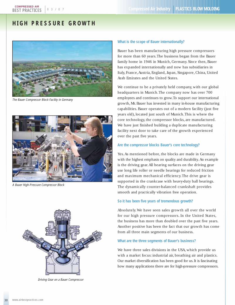
What is the scope of Bauer internationally?
Bauer has been manufacturing high pressure compressors
for more than 60 years.The business began from the Bauer
family home in 1946 in Munich, Germany. Since then, Bauer
has expanded internationally and now has subsidiaries in
Italy, France,Austria, England, Japan, Singapore, China, United
Arab Emirates and the United States.
We continue to be a privately held company, with our global
headquarters in Munich.The company now has over 700
employees and continues to grow.To support our international
growth, Mr. Bauer has invested in many in-house manufacturing
capabilities. Bauer operates out of a modern facility (just five
years old), located just south of Munich.This is where the
core technology, the compressor blocks, are manufactured.
We have just finished building a duplicate manufacturing
facility next door to take care of the growth experienced
over the past five years.
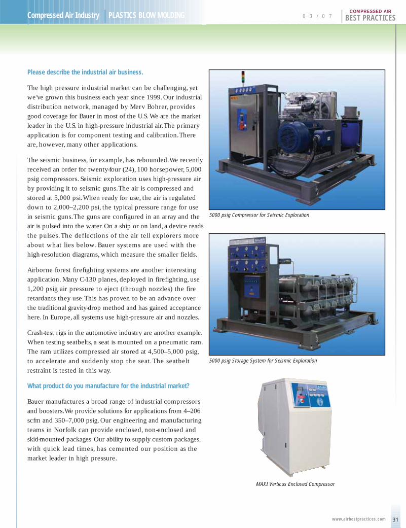
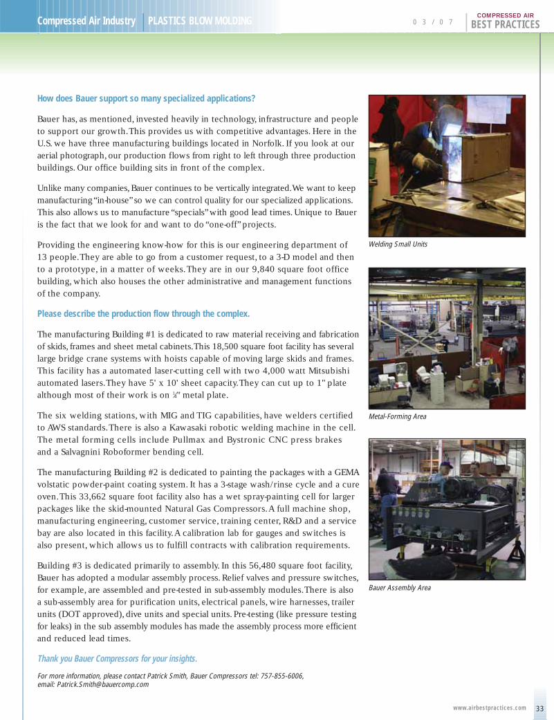
Are the compressor blocks Bauer’s core technology?
Yes.As mentioned before, the blocks are made in Germany
with the highest emphasis on quality and durability. An example
is the driving gear.All bearing surfaces on the driving gear
use long life roller or needle bearings for reduced friction
and maximum mechanical efficiency.The drive gear is
supported in the crankcase with heavy-duty ball bearings.
The dynamically counter-balanced crankshaft provides
smooth and practically vibration free operation.
So it has been five years of tremendous growth?
Absolutely.We have seen sales growth all over the world
for our high pressure compressors. In the United States,
the business has more than doubled over the past five years.
Another positive has been the fact that our growth has come
from all three main segments of our business.
What are the three segments of Bauer’s business?
We have three sales divisions in the USA, which provide us
with a market focus: industrial air, breathing air and plastics.
Our market diversification has been good for us. It is fascinating
how many applications there are for high-pressure compressors.
Driving Gear on a Bauer Compressor
A Bauer High-Pressure Compressor Block
The Bauer Compressor Block Facility in Germany
31
Compressed Air Industry | PLASTICS BLOW MOLDING 0 3 / 0 7 | BEST PRACTICESCOMPRESSED AIR
www.airbestpract ices.com
5000 psig Compressor for Seismic Exploration
5000 psig Storage System for Seismic Exploration
MAXI Verticus Enclosed Compressor
Please describe the industrial air business.
The high pressure industrial market can be challenging, yet
we’ve grown this business each year since 1999. Our industrial
distribution network, managed by Merv Bohrer, provides
good coverage for Bauer in most of the U.S. We are the market
leader in the U.S. in high-pressure industrial air.The primary
application is for component testing and calibration.There
are, however, many other applications.
The seismic business, for example, has rebounded.We recently
received an order for twenty-four (24), 100 horsepower, 5,000
psig compressors. Seismic exploration uses high-pressure air
by providing it to seismic guns.The air is compressed and
stored at 5,000 psi.When ready for use, the air is regulated
down to 2,000–2,200 psi, the typical pressure range for use
in seismic guns.The guns are configured in an array and the
air is pulsed into the water. On a ship or on land, a device reads
the pulses.The deflections of the air tell explorers more
about what lies below. Bauer systems are used with the
high-resolution diagrams, which measure the smaller fields.
Airborne forest firefighting systems are another interesting
application. Many C-130 planes, deployed in firefighting, use
1,200 psig air pressure to eject (through nozzles) the fire
retardants they use.This has proven to be an advance over
the traditional gravity-drop method and has gained acceptance
here. In Europe, all systems use high-pressure air and nozzles.
Crash-test rigs in the automotive industry are another example.
When testing seatbelts, a seat is mounted on a pneumatic ram.
The ram utilizes compressed air stored at 4,500–5,000 psig,
to accelerate and suddenly stop the seat.The seatbelt
restraint is tested in this way.
What product do you manufacture for the industrial market?
Bauer manufactures a broad range of industrial compressors
and boosters.We provide solutions for applications from 4–206
scfm and 350–7,000 psig. Our engineering and manufacturing
teams in Norfolk can provide enclosed, non-enclosed and
skid-mounted packages.Our ability to supply custom packages,
with quick lead times, has cemented our position as the
market leader in high pressure.

H I G H P R E S S U R E G R O W T H
32
BEST PRACTICES | 0 3 / 0 7 Compressed Air Industry | PLASTICS BLOW MOLDING
www.airbestpract ices.com
COMPRESSED AIR
How is the Natural Gas business?
Natural gas has lost the spotlight with NGV (Natural Gas Vehicle) larger fleets
in favor of bio-diesel and hydrogen.We were there when the NGV fleets were
set up and enjoyed a good run of business. Many large transit fleets have gone
towards over-the-fence renting of natural gas. Bauer continues to work with smaller
fleets, like forklift fleets at the cargo side of an airport.Truck fleets, with fifty
or fewer trucks, are also a target.A Long Island beer distributor, for example,
uses NGV trucks supplied by Bauer natural gas compressors.
Please describe your Nitrogen Compressors.
Nitrogen compressors are a major product for Bauer.We manufacture compressors
for inert gases. Nitrogen is used in many industrial test labs.We also supply
compressors for helium (helium recovery systems) and Argon.
Bauer also has a joint venture in California dedicated to providing nitrogen generators
for aircraft ground support.The FAA mandates the use of nitrogen in many areas
of helicopters and airplanes. Helicopters use nitrogen, under pressure, in the rotor
blades as a way to detect leaks.All tires on airplanes are inflated with nitrogen.
This joint venture specializes on military applications and has more than 200
units in service.
Breathing air is your second sales division, correct?
Yes. Industrial safety, through breathing air in refineries and other industrial
applications, is one part of this division.The larger part comes from supplying
high-pressure breathable air to fire departments and diving applications.
Big subsidies for fire departments, through FEMA grants after 9-11, gave this market
a big boost over the past few years. Bauer has a comprehensive product line
of breathing air compressors and systems.This market has now slowed down,
as most breathing air systems at fire departments have been upgraded over the
past five years.
We also manufacture our own purifiers, utilizing molecular sieve and catalysts,
which we package with our air compressors to provide breathing air.
How is your plastics sales division doing?
Our plastics sales division focuses on gas-assist injection molding. Gas-injection
molding is an innovative process that effectively reduces the weight of plastic
parts.We have specialists, in our U.S. branches, in the evaluation of molds and
who consult with molders on how to implement this new technology. Most
television housings, suitcase handles, toilet seats and clothes hangers are produced
with the gas-injection molding process.This is a growth market for Bauer as more
molding markets adopt this technology.
INDUSTRIAL APPLICATIONSBETWEEN 2,000–5,000 PSIG
Testing & CalibrationPressure GaugesRelief ValvesValvesTubing & PipeValve ActuatorsTransducers
ResearchIndustryEducationalHelium and Argon
Recovery
AutomotiveTest SledsWind Tunnel
Oil & GasOffshore Rig StabilizationPipeline Pressure Testing
MarineCable CompensationAir Guns for Seismic
ExplorationDockside Air Supply
AviationEngine StartingAircraft Maintenance
Electric Power PlantsTurbine StartingCircuit Breaking
Cylinder RefillingStoragePaintballAir Rifle
33
Compressed Air Industry | PLASTICS BLOW MOLDING 0 3 / 0 7 | BEST PRACTICESCOMPRESSED AIR
www.airbestpract ices.com
Bauer Assembly Area
How does Bauer support so many specialized applications?
Bauer has, as mentioned, invested heavily in technology, infrastructure and peopleto support our growth.This provides us with competitive advantages. Here in theU.S. we have three manufacturing buildings located in Norfolk. If you look at ouraerial photograph, our production flows from right to left through three productionbuildings. Our office building sits in front of the complex.
Unlike many companies,Bauer continues to be vertically integrated.We want to keepmanufacturing “in-house”so we can control quality for our specialized applications.This also allows us to manufacture “specials”with good lead times. Unique to Baueris the fact that we look for and want to do “one-off” projects.
Providing the engineering know-how for this is our engineering department of 13 people.They are able to go from a customer request, to a 3-D model and thento a prototype, in a matter of weeks.They are in our 9,840 square foot officebuilding, which also houses the other administrative and management functionsof the company.
Please describe the production flow through the complex.
The manufacturing Building #1 is dedicated to raw material receiving and fabricationof skids, frames and sheet metal cabinets.This 18,500 square foot facility has severallarge bridge crane systems with hoists capable of moving large skids and frames.This facility has a automated laser-cutting cell with two 4,000 watt Mitsubishiautomated lasers.They have 5' x 10' sheet capacity.They can cut up to 1" platealthough most of their work is on 1⁄4" metal plate.
The six welding stations, with MIG and TIG capabilities, have welders certified to AWS standards.There is also a Kawasaki robotic welding machine in the cell.The metal forming cells include Pullmax and Bystronic CNC press brakes and a Salvagnini Roboformer bending cell.
The manufacturing Building #2 is dedicated to painting the packages with a GEMAvolstatic powder-paint coating system. It has a 3-stage wash/rinse cycle and a cureoven.This 33,662 square foot facility also has a wet spray-painting cell for largerpackages like the skid-mounted Natural Gas Compressors.A full machine shop,manufacturing engineering, customer service, training center, R&D and a servicebay are also located in this facility.A calibration lab for gauges and switches isalso present, which allows us to fulfill contracts with calibration requirements.
Building #3 is dedicated primarily to assembly. In this 56,480 square foot facility,Bauer has adopted a modular assembly process. Relief valves and pressure switches,for example, are assembled and pre-tested in sub-assembly modules.There is alsoa sub-assembly area for purification units, electrical panels, wire harnesses, trailerunits (DOT approved), dive units and special units. Pre-testing (like pressure testingfor leaks) in the sub assembly modules has made the assembly process more efficientand reduced lead times.
Thank you Bauer Compressors for your insights.
For more information, please contact Patrick Smith, Bauer Compressors tel: 757-855-6006, email: [email protected]
Welding Small Units
Metal-Forming Area
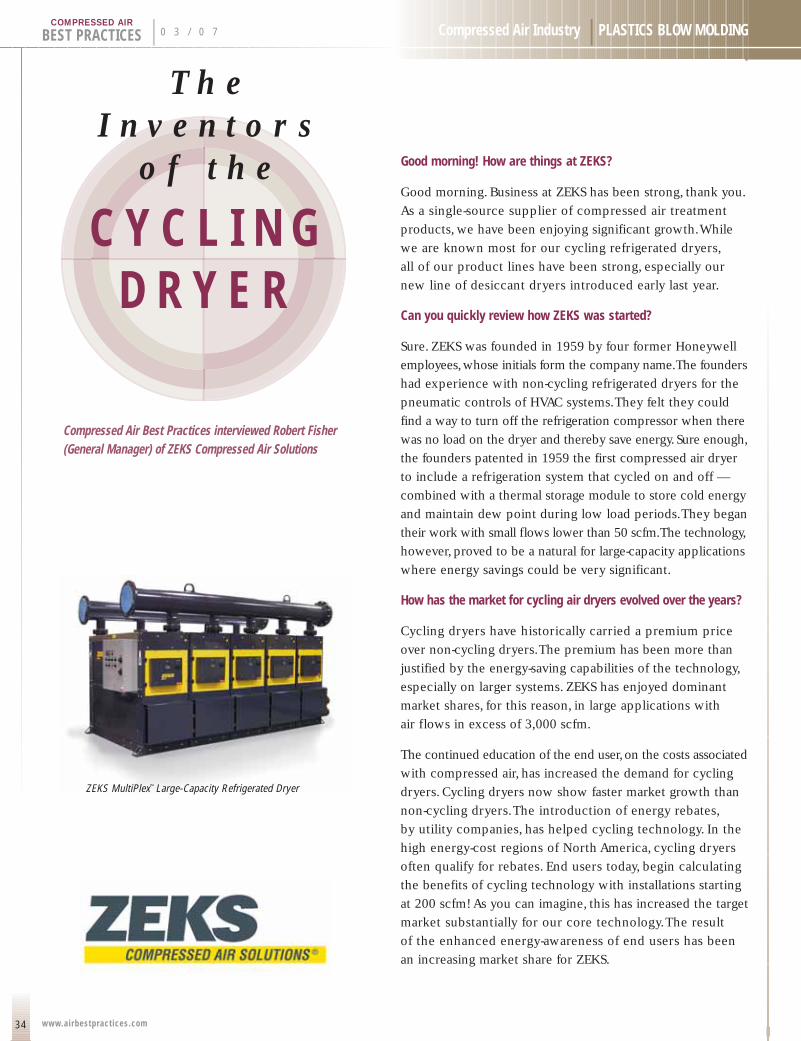
Compressed Air Best Practices interviewed Robert Fisher(General Manager) of ZEKS Compressed Air Solutions
34
BEST PRACTICES | 0 3 / 0 7 Compressed Air Industry | PLASTICS BLOW MOLDING
www.airbestpract ices.com
COMPRESSED AIR
Good morning! How are things at ZEKS?
Good morning. Business at ZEKS has been strong, thank you.
As a single-source supplier of compressed air treatment
products, we have been enjoying significant growth.While
we are known most for our cycling refrigerated dryers,
all of our product lines have been strong, especially our
new line of desiccant dryers introduced early last year.
Can you quickly review how ZEKS was started?
Sure. ZEKS was founded in 1959 by four former Honeywell
employees,whose initials form the company name.The founders
had experience with non-cycling refrigerated dryers for the
pneumatic controls of HVAC systems.They felt they could
find a way to turn off the refrigeration compressor when there
was no load on the dryer and thereby save energy. Sure enough,
the founders patented in 1959 the first compressed air dryer
to include a refrigeration system that cycled on and off —
combined with a thermal storage module to store cold energy
and maintain dew point during low load periods.They began
their work with small flows lower than 50 scfm.The technology,
however, proved to be a natural for large-capacity applications
where energy savings could be very significant.
How has the market for cycling air dryers evolved over the years?
Cycling dryers have historically carried a premium price
over non-cycling dryers.The premium has been more than
justified by the energy-saving capabilities of the technology,
especially on larger systems. ZEKS has enjoyed dominant
market shares, for this reason, in large applications with
air flows in excess of 3,000 scfm.
The continued education of the end user,on the costs associated
with compressed air, has increased the demand for cycling
dryers. Cycling dryers now show faster market growth than
non-cycling dryers.The introduction of energy rebates,
by utility companies, has helped cycling technology. In the
high energy-cost regions of North America, cycling dryers
often qualify for rebates. End users today, begin calculating
the benefits of cycling technology with installations starting
at 200 scfm! As you can imagine, this has increased the target
market substantially for our core technology.The result
of the enhanced energy-awareness of end users has been
an increasing market share for ZEKS.
ZEKS MultiPlex™ Large-Capacity Refrigerated Dryer
C Y C L I N G D R Y E R
T h eI n v e n t o r s
o f t h e
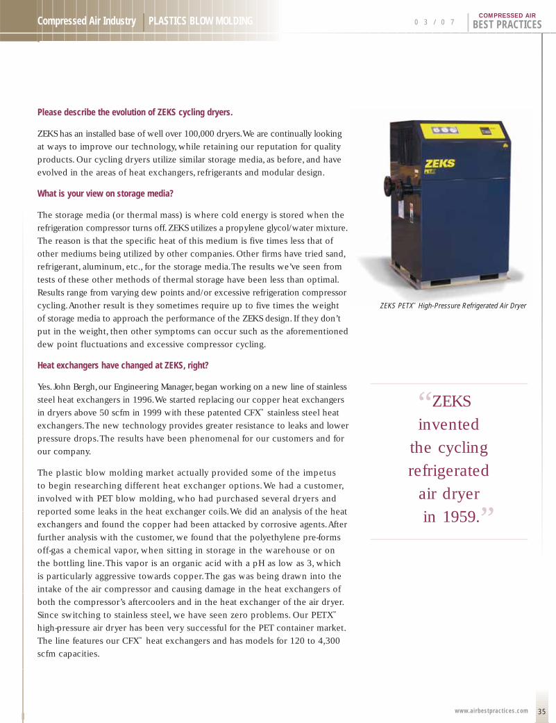
35
Compressed Air Industry | PLASTICS BLOW MOLDING 0 3 / 0 7 | BEST PRACTICESCOMPRESSED AIR
www.airbestpract ices.com
Please describe the evolution of ZEKS cycling dryers.
ZEKS has an installed base of well over 100,000 dryers.We are continually looking
at ways to improve our technology, while retaining our reputation for quality
products. Our cycling dryers utilize similar storage media, as before, and have
evolved in the areas of heat exchangers, refrigerants and modular design.
What is your view on storage media?
The storage media (or thermal mass) is where cold energy is stored when the
refrigeration compressor turns off.ZEKS utilizes a propylene glycol/water mixture.
The reason is that the specific heat of this medium is five times less that of
other mediums being utilized by other companies. Other firms have tried sand,
refrigerant, aluminum, etc., for the storage media.The results we’ve seen from
tests of these other methods of thermal storage have been less than optimal.
Results range from varying dew points and/or excessive refrigeration compressor
cycling.Another result is they sometimes require up to five times the weight
of storage media to approach the performance of the ZEKS design. If they don’t
put in the weight, then other symptoms can occur such as the aforementioned
dew point fluctuations and excessive compressor cycling.
Heat exchangers have changed at ZEKS, right?
Yes. John Bergh,our Engineering Manager,began working on a new line of stainless
steel heat exchangers in 1996.We started replacing our copper heat exchangers
in dryers above 50 scfm in 1999 with these patented CFX™ stainless steel heat
exchangers.The new technology provides greater resistance to leaks and lower
pressure drops.The results have been phenomenal for our customers and for
our company.
The plastic blow molding market actually provided some of the impetus
to begin researching different heat exchanger options.We had a customer,
involved with PET blow molding, who had purchased several dryers and
reported some leaks in the heat exchanger coils.We did an analysis of the heat
exchangers and found the copper had been attacked by corrosive agents.After
further analysis with the customer, we found that the polyethylene pre-forms
off-gas a chemical vapor, when sitting in storage in the warehouse or on
the bottling line.This vapor is an organic acid with a pH as low as 3, which
is particularly aggressive towards copper.The gas was being drawn into the
intake of the air compressor and causing damage in the heat exchangers of
both the compressor’s aftercoolers and in the heat exchanger of the air dryer.
Since switching to stainless steel, we have seen zero problems. Our PETX™
high-pressure air dryer has been very successful for the PET container market.
The line features our CFX™ heat exchangers and has models for 120 to 4,300
scfm capacities.
ZEKS PETX™ High-Pressure Refrigerated Air Dryer
“ZEKS .
invented
the cycling
refrigerated
air dryer
in 1959.”
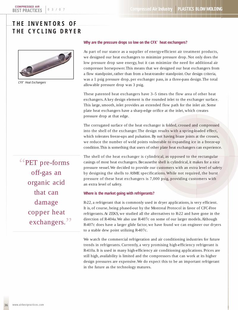
T H E I N V E N T O R S O FT H E C Y C L I N G D R Y E R
36
BEST PRACTICES | 0 3 / 0 7 Compressed Air Industry | PLASTICS BLOW MOLDING
www.airbestpract ices.com
COMPRESSED AIR
Why are the pressure drops so low on the CFX™ heat exchangers?
As part of our stance as a supplier of energy-efficient air treatment products,
we designed our heat exchangers to minimize pressure drop. Not only does the
low pressure drop save energy, but it can minimize the need for additional air
compressor horsepower.This means that we designed our heat exchangers from
a flow standpoint, rather than from a heat-transfer standpoint. Our design criteria,
was a 1 psig pressure drop, per exchanger pass, in a three-pass design.The total
allowable pressure drop was 3 psig.
These patented heat exchangers have 3–5 times the flow area of other heat
exchangers.A key design element is the rounded inlet to the exchanger surface.
This large, smooth, inlet provides an extended flow path for the inlet air. Some
plate heat exchangers have a sharp-edge orifice at the inlet, which creates
pressure drop at that edge.
The corrugated surface of the heat exchanger is folded, crossed and compressed
into the shell of the exchanger.The design results with a spring-loaded effect,
which tolerates freeze-ups and pulsation. By not having braze joints at the crosses,
we reduce the number of weld points vulnerable to expanding ice in a freeze-up
condition.This is something that users of other plate heat exchangers can experience.
The shell of the heat exchanger is cylindrical, as opposed to the rectangular
casings of most heat exchangers. Becausethe shell is cylindrical, it makes for a nice
pressure vessel.We decided to provide our customers with an extra level of safety
by designing the shells to ASME specifications.While not required, the burst
pressure of these heat exchangers is 7,000 psig, providing customers with
an extra level of safety.
Where is the market going with refrigerants?
R-22, a refrigerant that is commonly used in dryer applications, is very efficient.
It is, of course, being phased-out by the Montreal Protocol in favor of CFC-Free
refrigerants.At ZEKS, we studied all the alternatives to R-22 and have gone in the
direction of R-404a.We also use R-407c on some of our larger models.Although
R-407c does have a larger glide factor, we have found we can engineer our dryers
to a stable dew point utilizing R-407c.
We watch the commercial refrigeration and air conditioning industries for future
trends in refrigerants. Currently, a very promising high-efficiency refrigerant is
R-410a. It is used in many high-efficiency air conditioning applications. Prices are
still high, availability is limited and the compressors that can work at its higher
design pressures are expensive.We do expect this to be an important refrigerant
in the future as the technology matures.
CFX™ Heat Exchangers
“PET pre-forms .
off-gas an
organic acid
that can
damage
copper heat
exchangers.”

37
Compressed Air Industry | PLASTICS BLOW MOLDING 0 3 / 0 7 | BEST PRACTICESCOMPRESSED AIR
www.airbestpract ices.com
Let’s talk about modularity and redundancy.
Many end users have multiple air dryers in their facility, each of which is creating
a pressure drop of, on average, 5 psig. Servicing multiple dryers also creates
challenges in finding times when they are off-load to work on them.When the
business of a customer grows, more dryers are added, which make the system
even less efficient and more complex. Our customers asked us to find a solution
to these problems.
The solution arrived more than 15 years ago with the introduction of the MultiPlex™
Series of cycling refrigerated air dryers.These dryers are made up of multiple,
independent, cycling air treatment modules — within one large dryer. In 2002,
we redesigned these dryers with our CFX™ heat exchangers.The modules share
a single inlet header and a single outlet header, each with dual connection capability
for installation versatility.The modules turn on and off as the load characteristics
require, to deliver energy savings of up to 80%.We currently manufacture units
of up to 8 modules for an air flow of 19,200 scfm.
Expandability is also possible as the header centerline position is common among
all the models (4,000 scfm and larger).This feature enables users to “bolt-on”additional
units as operations expand. Dryer operations, of all the modules, is automatically
controlled and synchronized to optimize energy savings.A PLC manages the
appropriate loading and unloading of the modules required to maintain dew
point.A backlit LCD display provides the user with operating information
and a control interface.
Finally, the design is great for service because each module can be isolated from
the others.This allows for service to be performed on the module while the other
modules are in operation.The other benefit is that all the modules are the same in
design.This leads to increased levels of familiarity and expertise by service technicians.
On another topic, what does the Ingersoll Rand acquisition mean for ZEKS?
Ingersoll Rand acquired ZEKS on September 1, 2006.The previous owner had
purchased ZEKS in 1996. One of the reasons Ingersoll Rand was seen as an attractive
buyer was the additional volume that they could bring to the ZEKS facility.
Ingersoll Rand also has a great deal of knowledge of the markets outside of North
America where ZEKS has been weak.
ZEKS will be producing certain dryer products under the Ingersoll Rand name
for Ingersoll Rand.There will be a degree of differentiation between ZEKS and
Ingersoll Rand products.The sales, marketing and service of the Ingersoll Rand
business is completely separate from the ZEKS business.The ZEKS Regional
Managers as well as Inside Sales will continue to be 100% focused on ZEKS
equipment and ZEKS distributors.
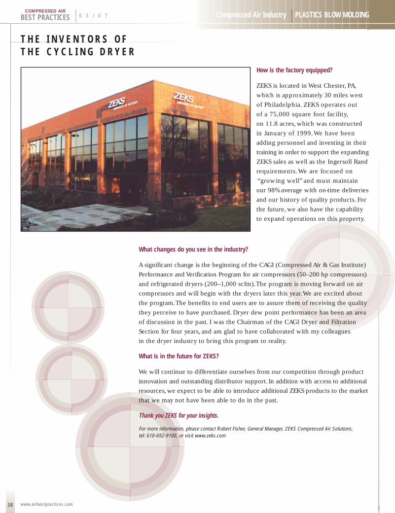
T H E I N V E N T O R S O FT H E C Y C L I N G D R Y E R
38
BEST PRACTICES | 0 3 / 0 7 Compressed Air Industry | PLASTICS BLOW MOLDING
www.airbestpract ices.com
COMPRESSED AIR
How is the factory equipped?
ZEKS is located in West Chester, PA,
which is approximately 30 miles west
of Philadelphia. ZEKS operates out
of a 75,000 square foot facility,
on 11.8 acres, which was constructed
in January of 1999.We have been
adding personnel and investing in their
training in order to support the expanding
ZEKS sales as well as the Ingersoll Rand
requirements.We are focused on
“growing well” and must maintain
our 98% average with on-time deliveries
and our history of quality products. For
the future, we also have the capability
to expand operations on this property.
What changes do you see in the industry?
A significant change is the beginning of the CAGI (Compressed Air & Gas Institute)
Performance and Verification Program for air compressors (50–200 hp compressors)
and refrigerated dryers (200–1,000 scfm).The program is moving forward on air
compressors and will begin with the dryers later this year.We are excited about
the program.The benefits to end users are to assure them of receiving the quality
they perceive to have purchased. Dryer dew point performance has been an area
of discussion in the past. I was the Chairman of the CAGI Dryer and Filtration
Section for four years, and am glad to have collaborated with my colleagues
in the dryer industry to bring this program to reality.
What is in the future for ZEKS?
We will continue to differentiate ourselves from our competition through product
innovation and outstanding distributor support. In addition with access to additional
resources, we expect to be able to introduce additional ZEKS products to the market
that we may not have been able to do in the past.
Thank you ZEKS for your insights.
For more information, please contact Robert Fisher, General Manager, ZEKS Compressed Air Solutions, tel: 610-692-9100, or visit www.zeks.com
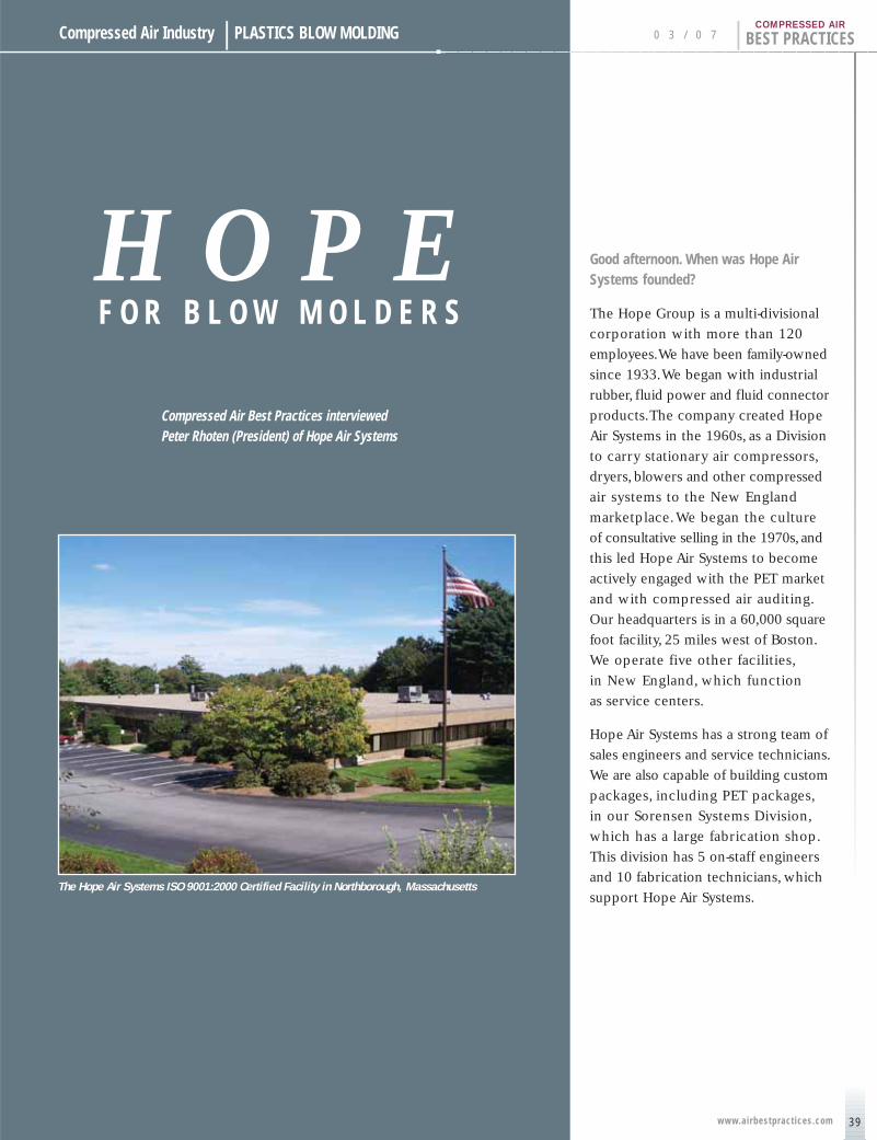
39
Compressed Air Industry | PLASTICS BLOW MOLDING
H O P EF O R B L O W M O L D E R S
Compressed Air Best Practices interviewedPeter Rhoten (President) of Hope Air Systems
0 3 / 0 7 | BEST PRACTICESCOMPRESSED AIR
www.airbestpract ices.com
Good afternoon. When was Hope AirSystems founded?
The Hope Group is a multi-divisional
corporation with more than 120
employees.We have been family-owned
since 1933.We began with industrial
rubber, fluid power and fluid connector
products.The company created Hope
Air Systems in the 1960s, as a Division
to carry stationary air compressors,
dryers, blowers and other compressed
air systems to the New England
marketplace.We began the culture
of consultative selling in the 1970s, and
this led Hope Air Systems to become
actively engaged with the PET market
and with compressed air auditing.
Our headquarters is in a 60,000 square
foot facility, 25 miles west of Boston.
We operate five other facilities,
in New England, which function
as service centers.
Hope Air Systems has a strong team of
sales engineers and service technicians.
We are also capable of building custom
packages, including PET packages,
in our Sorensen Systems Division,
which has a large fabrication shop.
This division has 5 on-staff engineers
and 10 fabrication technicians, which
support Hope Air Systems.The Hope Air Systems ISO 9001:2000 Certified Facility in Northborough, Massachusetts
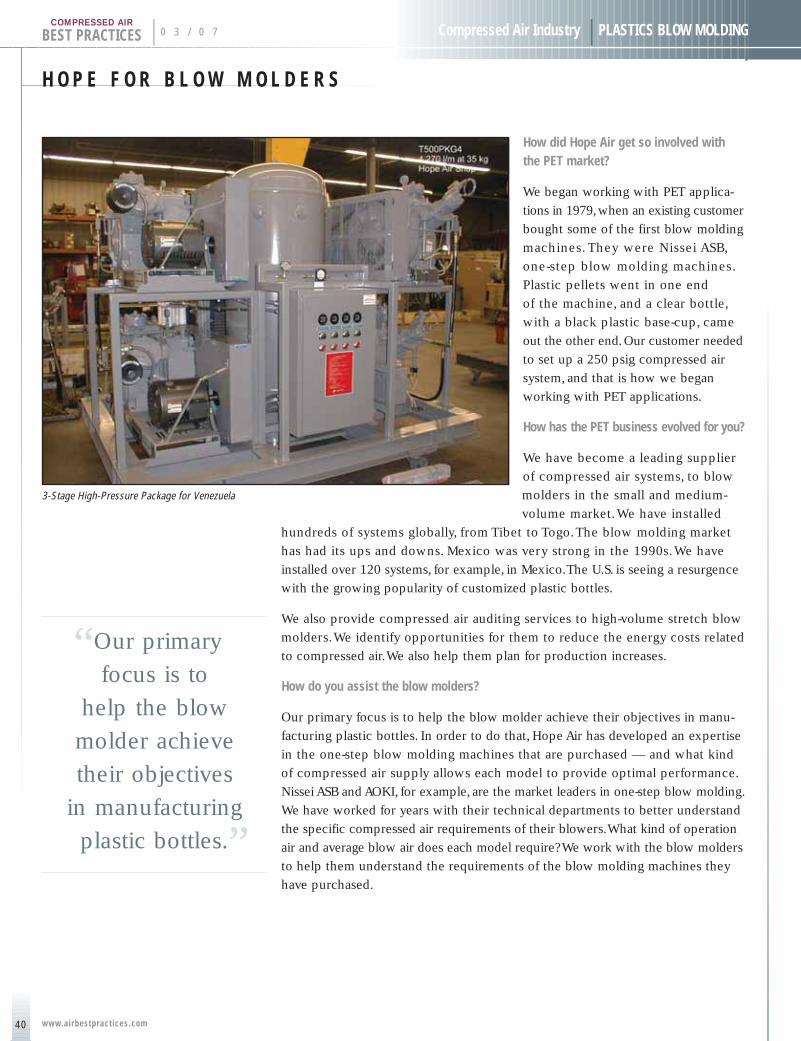
H O P E F O R B L O W M O L D E R S
40
BEST PRACTICES | 0 3 / 0 7 Compressed Air Industry | PLASTICS BLOW MOLDING
www.airbestpract ices.com
COMPRESSED AIR
How did Hope Air get so involved with the PET market?
We began working with PET applica-
tions in 1979,when an existing customer
bought some of the first blow molding
machines. They were Nissei ASB,
one-step blow molding machines.
Plastic pellets went in one end
of the machine, and a clear bottle,
with a black plastic base-cup, came
out the other end.Our customer needed
to set up a 250 psig compressed air
system, and that is how we began
working with PET applications.
How has the PET business evolved for you?
We have become a leading supplier
of compressed air systems, to blow
molders in the small and medium-
volume market.We have installed
hundreds of systems globally, from Tibet to Togo.The blow molding market
has had its ups and downs. Mexico was very strong in the 1990s.We have
installed over 120 systems, for example, in Mexico.The U.S. is seeing a resurgence
with the growing popularity of customized plastic bottles.
We also provide compressed air auditing services to high-volume stretch blow
molders.We identify opportunities for them to reduce the energy costs related
to compressed air.We also help them plan for production increases.
How do you assist the blow molders?
Our primary focus is to help the blow molder achieve their objectives in manu-
facturing plastic bottles. In order to do that, Hope Air has developed an expertise
in the one-step blow molding machines that are purchased — and what kind
of compressed air supply allows each model to provide optimal performance.
Nissei ASB and AOKI, for example, are the market leaders in one-step blow molding.
We have worked for years with their technical departments to better understand
the specific compressed air requirements of their blowers.What kind of operation
air and average blow air does each model require? We work with the blow molders
to help them understand the requirements of the blow molding machines they
have purchased.
3-Stage High-Pressure Package for Venezuela
“Our primary .
focus is to
help the blow
molder achieve
their objectives
in manufacturing
plastic bottles.”
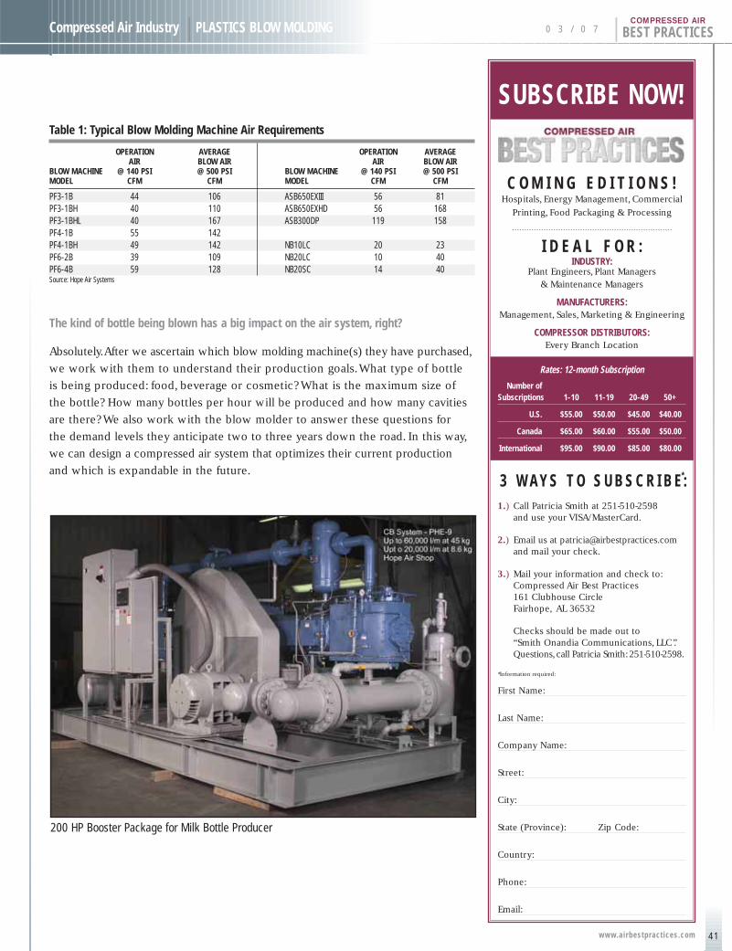
41
Compressed Air Industry | PLASTICS BLOW MOLDING 0 3 / 0 7 | BEST PRACTICESCOMPRESSED AIR
www.airbestpract ices.com
Table 1: Typical Blow Molding Machine Air Requirements
OPERATION AVERAGE OPERATION AVERAGE AIR BLOW AIR AIR BLOW AIR
BLOW MACHINE @ 140 PSI @ 500 PSI BLOW MACHINE @ 140 PSI @ 500 PSIMODEL CFM CFM MODEL CFM CFM
PF3-1B 44 106 ASB650EXIII 56 81PF3-1BH 40 110 ASB650EXHD 56 168PF3-1BHL 40 167 ASB300DP 119 158PF4-1B 55 142PF4-1BH 49 142 NB10LC 20 23PF6-2B 39 109 NB20LC 10 40PF6-4B 59 128 NB20SC 14 40Source: Hope Air Systems
The kind of bottle being blown has a big impact on the air system, right?
Absolutely.After we ascertain which blow molding machine(s) they have purchased,
we work with them to understand their production goals.What type of bottle
is being produced: food, beverage or cosmetic? What is the maximum size of
the bottle? How many bottles per hour will be produced and how many cavities
are there? We also work with the blow molder to answer these questions for
the demand levels they anticipate two to three years down the road. In this way,
we can design a compressed air system that optimizes their current production
and which is expandable in the future.
200 HP Booster Package for Milk Bottle Producer
SUBSCRIBE NOW!
C O M I N G E D I T I O N S !Hospitals, Energy Management, Commercial
Printing, Food Packaging & Processing
I D E A L F O R :INDUSTRY:
Plant Engineers, Plant Managers & Maintenance Managers
MANUFACTURERS:Management, Sales, Marketing & Engineering
COMPRESSOR DISTRIBUTORS:Every Branch Location
Rates: 12-month Subscription
Number of Subscriptions 1-10 11-19 20-49 50+
U.S. $55.00 $50.00 $45.00 $40.00
Canada $65.00 $60.00 $55.00 $50.00
International $95.00 $90.00 $85.00 $80.00
3 W A Y S T O S U B S C R I B E :*
1.) Call Patricia Smith at 251-510-2598 and use your VISA/MasterCard.
2.) Email us at [email protected] mail your check.
3.) Mail your information and check to:Compressed Air Best Practices161 Clubhouse CircleFairhope, AL 36532
Checks should be made out to “Smith Onandia Communications, LLC”.Questions,call Patricia Smith:251-510-2598.
*Information required:
First Name:
Last Name:
Company Name:
Street:
City:
State (Province): Zip Code:
Country:
Phone:
Email:
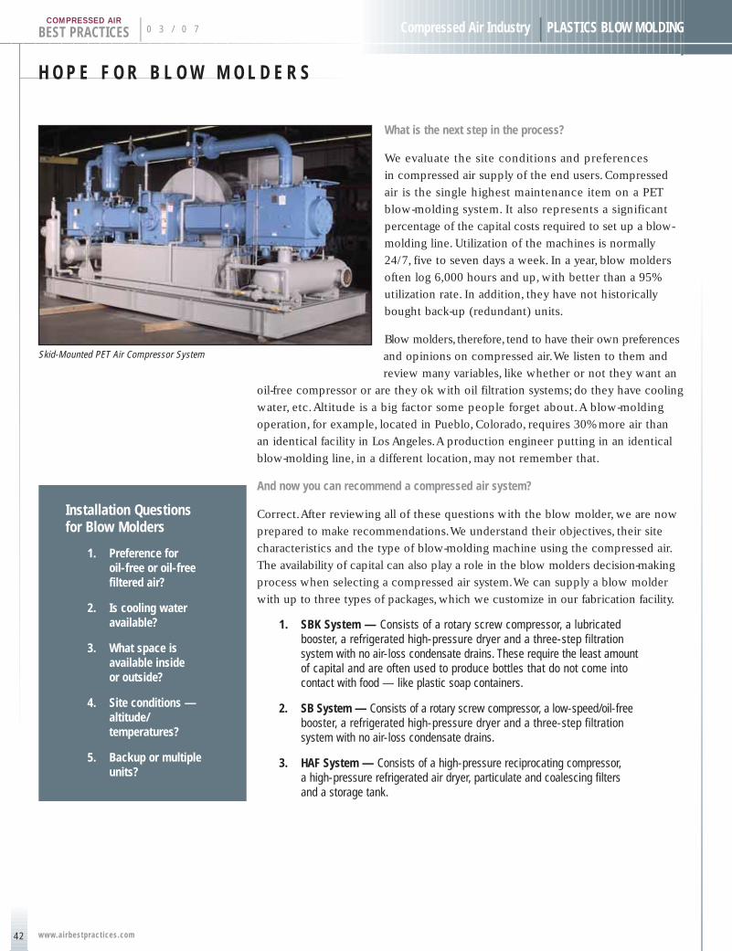
H O P E F O R B L O W M O L D E R S
42
BEST PRACTICES | 0 3 / 0 7 Compressed Air Industry | PLASTICS BLOW MOLDING
www.airbestpract ices.com
COMPRESSED AIR
What is the next step in the process?
We evaluate the site conditions and preferences
in compressed air supply of the end users. Compressed
air is the single highest maintenance item on a PET
blow-molding system. It also represents a significant
percentage of the capital costs required to set up a blow-
molding line. Utilization of the machines is normally
24/7, five to seven days a week. In a year, blow molders
often log 6,000 hours and up, with better than a 95%
utilization rate. In addition, they have not historically
bought back-up (redundant) units.
Blow molders, therefore, tend to have their own preferences
and opinions on compressed air.We listen to them and
review many variables, like whether or not they want an
oil-free compressor or are they ok with oil filtration systems; do they have cooling
water, etc.Altitude is a big factor some people forget about.A blow-molding
operation, for example, located in Pueblo, Colorado, requires 30% more air than
an identical facility in Los Angeles.A production engineer putting in an identical
blow-molding line, in a different location, may not remember that.
And now you can recommend a compressed air system?
Correct.After reviewing all of these questions with the blow molder, we are now
prepared to make recommendations.We understand their objectives, their site
characteristics and the type of blow-molding machine using the compressed air.
The availability of capital can also play a role in the blow molders decision-making
process when selecting a compressed air system.We can supply a blow molder
with up to three types of packages, which we customize in our fabrication facility.
1. SBK System — Consists of a rotary screw compressor, a lubricatedbooster, a refrigerated high-pressure dryer and a three-step filtration system with no air-loss condensate drains. These require the least amountof capital and are often used to produce bottles that do not come into contact with food — like plastic soap containers.
2. SB System — Consists of a rotary screw compressor, a low-speed/oil-freebooster, a refrigerated high-pressure dryer and a three-step filtration system with no air-loss condensate drains.
3. HAF System — Consists of a high-pressure reciprocating compressor,a high-pressure refrigerated air dryer, particulate and coalescing filtersand a storage tank.
Installation Questions for Blow Molders
1. Preference for oil-free or oil-freefiltered air?
2. Is cooling wateravailable?
3. What space isavailable inside or outside?
4. Site conditions —altitude/temperatures?
5. Backup or multipleunits?
Skid-Mounted PET Air Compressor System
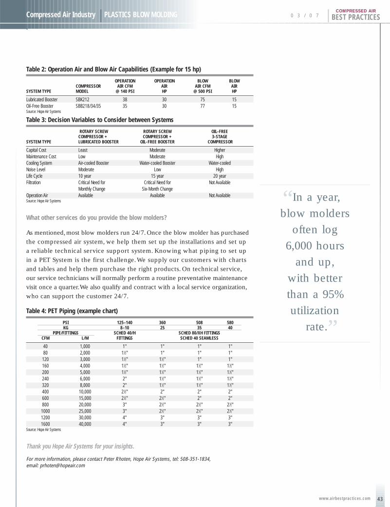
43
Compressed Air Industry | PLASTICS BLOW MOLDING 0 3 / 0 7 | BEST PRACTICESCOMPRESSED AIR
www.airbestpract ices.com
Table 2: Operation Air and Blow Air Capabilities (Example for 15 hp)
OPERATION OPERATION BLOW BLOWCOMPRESSOR AIR CFM AIR AIR CFM AIR
SYSTEM TYPE MODEL @ 140 PSI HP @ 500 PSI HP
Lubricated Booster SBK212 38 30 75 15Oil-Free Booster SBB218/34/35 35 30 77 15Source: Hope Air Systems
Table 3: Decision Variables to Consider between Systems
ROTARY SCREW ROTARY SCREW OIL-FREECOMPRESSOR + COMPRESSOR + 3-STAGE
SYSTEM TYPE LUBRICATED BOOSTER OIL-FREE BOOSTER COMPRESSOR
Capital Cost Least Moderate HigherMaintenance Cost Low Moderate HighCooling System Air-cooled Booster Water-cooled Booster Water-cooledNoise Level Moderate Low HighLife Cycle 10 year 15 year 20 yearFiltration Critical Need for Critical Need for Not Available
Monthly Change Six-Month ChangeOperation Air Available Available Not AvailableSource: Hope Air Systems
What other services do you provide the blow molders?
As mentioned, most blow molders run 24/7. Once the blow molder has purchased
the compressed air system, we help them set up the installations and set up
a reliable technical service support system. Knowing what piping to set up
in a PET System is the first challenge.We supply our customers with charts
and tables and help them purchase the right products. On technical service,
our service technicians will normally perform a routine preventative maintenance
visit once a quarter.We also qualify and contract with a local service organization,
who can support the customer 24/7.
Table 4: PET Piping (example chart)
PSI 125–140 360 508 580KG 8–10 25 35 40
PIPE/FITTINGS SCHED 40/H SCHED 80/XH FITTINGS CFM L/M FITTINGS SCHED 40 SEAMLESS
40 1,000 1" 1" 1" 1"80 2,000 11⁄2" 1" 1" 1"120 3,000 11⁄2" 11⁄2" 1" 1"160 4,000 11⁄2" 11⁄2" 11⁄2" 11⁄2"200 5,000 11⁄2" 11⁄2" 11⁄2" 11⁄2"240 6,000 2" 11⁄2" 11⁄2" 11⁄2"320 8,000 2" 11⁄2" 11⁄2" 11⁄2"400 10,000 21⁄2" 2" 2" 2"600 15,000 21⁄2" 21⁄2" 2" 2"800 20,000 3" 21⁄2" 21⁄2" 21⁄2"
1000 25,000 3" 21⁄2" 21⁄2" 21⁄2"1200 30,000 4" 3" 3" 3"1600 40,000 4" 3" 3" 3"
Source: Hope Air Systems
Thank you Hope Air Systems for your insights.
For more information, please contact Peter Rhoten, Hope Air Systems, tel: 508-351-1834, email: [email protected]
“In a year, .
blow molders
often log
6,000 hours
and up,
with better
than a 95%
utilization
rate.”
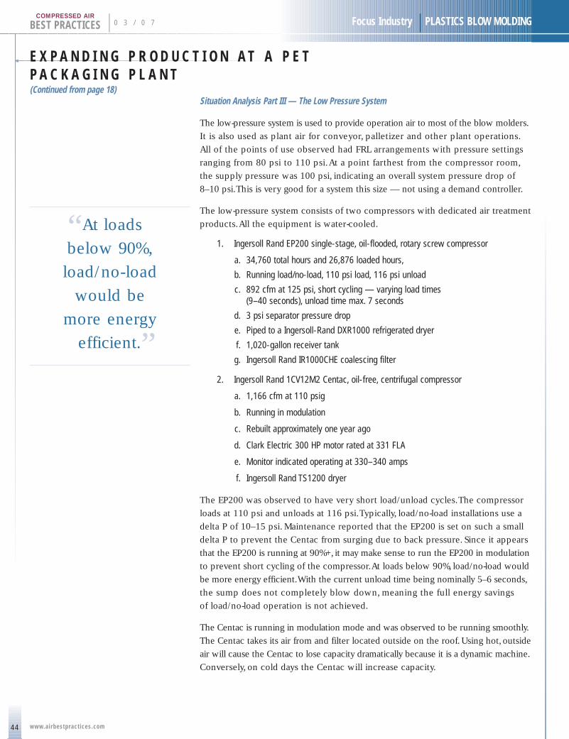
E X P A N D I N G P R O D U C T I O N A T A P E TP A C K A G I N G P L A N T(Continued from page 18)
44
BEST PRACTICES | 0 3 / 0 7 Focus Industry | PLASTICS BLOW MOLDING
www.airbestpract ices.com
COMPRESSED AIR
Situation Analysis Part III — The Low Pressure System
The low-pressure system is used to provide operation air to most of the blow molders.
It is also used as plant air for conveyor, palletizer and other plant operations.
All of the points of use observed had FRL arrangements with pressure settings
ranging from 80 psi to 110 psi.At a point farthest from the compressor room,
the supply pressure was 100 psi, indicating an overall system pressure drop of
8–10 psi.This is very good for a system this size — not using a demand controller.
The low-pressure system consists of two compressors with dedicated air treatment
products.All the equipment is water-cooled.
1. Ingersoll Rand EP200 single-stage, oil-flooded, rotary screw compressor
a. 34,760 total hours and 26,876 loaded hours,
b. Running load/no-load, 110 psi load, 116 psi unload
c. 892 cfm at 125 psi, short cycling — varying load times (9–40 seconds), unload time max. 7 seconds
d. 3 psi separator pressure drop
e. Piped to a Ingersoll-Rand DXR1000 refrigerated dryer
f. 1,020-gallon receiver tank
g. Ingersoll Rand IR1000CHE coalescing filter
2. Ingersoll Rand 1CV12M2 Centac, oil-free, centrifugal compressor
a. 1,166 cfm at 110 psig
b. Running in modulation
c. Rebuilt approximately one year ago
d. Clark Electric 300 HP motor rated at 331 FLA
e. Monitor indicated operating at 330–340 amps
f. Ingersoll Rand TS1200 dryer
The EP200 was observed to have very short load/unload cycles.The compressor
loads at 110 psi and unloads at 116 psi.Typically, load/no-load installations use a
delta P of 10–15 psi. Maintenance reported that the EP200 is set on such a small
delta P to prevent the Centac from surging due to back pressure. Since it appears
that the EP200 is running at 90%+, it may make sense to run the EP200 in modulation
to prevent short cycling of the compressor.At loads below 90%, load/no-load would
be more energy efficient.With the current unload time being nominally 5–6 seconds,
the sump does not completely blow down, meaning the full energy savings
of load/no-load operation is not achieved.
The Centac is running in modulation mode and was observed to be running smoothly.
The Centac takes its air from and filter located outside on the roof. Using hot, outside
air will cause the Centac to lose capacity dramatically because it is a dynamic machine.
Conversely, on cold days the Centac will increase capacity.
“At loads .
below 90%,
load/no-load
would be
more energy
efficient.”

45
Focus Industry | PLASTICS BLOW MOLDING 0 3 / 0 7 | BEST PRACTICESCOMPRESSED AIR
www.airbestpract ices.com
The piping system consists of a main 4" loop that reduces
to 2" shortly into the plant.There are numerous branches
and drops. Point-of-use regulation seems to do a good job,
as the pressure drop in the system is on the order of 8–10
psi for 1,000' plus of piping.There is a cross-over regulator
off of Belliss #1 that can provide back-up air, if required
and if there is sufficient high-pressure capacity.
Low-Pressure System Conclusions
The low-pressure system appears to be adequate for the
planned expansion.However,any additional air-using equipment
should be carefully considered to ensure that there is sufficient
low-pressure air. Please note this is a qualitative analysis
and should be followed up with flow metering to determine
actual use. In addition, flow and kW metering could determine
areas for energy savings, such as demand flow controllers,
extra storage and other possible equipment.
If either the rotary or centrifugal are down for maintenance,
there is not enough plant air.The centrifugal appears to
be running approximately 60%–70% loaded and the rotary
is running 80–90% loaded. Based on the machine flow ratings,
the centrifugal load is about 755 cfm (65%) and the rotary
load is also about 755 cfm (85%).The leftover capacity
is about 407 cfm in the centrifugal and 137 cfm in the rotary,
for a total of 544 cfm in reserve capacity.There is a cross-over
reducer to the high-pressure system, but its availability is
uncertain due to demand limits in the high-pressure system.
There is no backup in the low-pressure air system. Based on
current demand, an additional Ingersoll Rand EP200 system
would be sufficient. However, there are more energy-efficient
solutions available and if other changes are made, cascading
pressure-reducers from the high-pressure and medium-pressure
system could provide sufficient backup.
Situation Analysis Part IV: Energy Costs Associated with Compressor Systems
The electrical energy costs, required to run both the low-
pressure and high-pressure systems, is outlined below.
The low-pressure system, providing 110 psi air, is estimated
to cost $139,721 per year.The high-pressure system, providing
600, 500 and 150 psi air, is estimated to generate $512,278
in kW costs per year.The total kW energy costs for the current
system are estimated at $651,999.
Table 5: Current System kW Costs (including use of the proposedAoki and Mag)
FULL LOAD COST @ $.038 MODEL CFM KW KW/YR PER KWH
Centac 1CV 1166 Icfm 243.3 2,130,965 $80,977SSR EP200 892 cfm 176.5 1,545,905 $58,744
$139,721 110 psi CostBased on 4,563 cfm demand, including reducing valve losses and 150 psi use
Belliss 1 WH28 730 cfm 227.7 1,116,967 $42,445 50% loadedBelliss 2 WH28 730 cfm 227.7 1,994,583 $75,794Belliss 3 WH28 730 cfm 227.7 1,994,583 $75,794Belliss 4 WH40 1,100 cfm 389.2 3,409,544 $129,563Belliss 5 WH28 730 cfm 227.7 1,555,775 $59,119 75% loadedBelliss 6 WH28 1,100 cfm 389.2 3,409,544 $129,563
$512,278 600, 500 and150 psi Cost
$651,999 Total kW Cost
Action Plan: Three Alternatives to Consider
The objective is to provide this PET packaging facility withan air system that will allow it to expand, with the bestreturn-on-investment possible. Providing for some type of backup would also be a positive factor.The facility hasrequirements for air at 110 psi, 150 psi, 500 psi and 600 psi.There are three alternatives to consider:
1. Install a new, 600 psi, high-pressure Bellis & Morcom System
2. Install a dedicated 150 psi Compressor Systemand Piping Loop
3. Install a dedicated 150 psi Compressor Systemand Piping Loop — and a dedicated 500 psiPiping Loop
Action Plan Alternative 1: Installing a New 600 psi System
The anticipated demand is such that a new Bellis & MorcomSystem would primarily stand idle. It would be used duringthe peak production periods in the hot summer months,whenthe current system isn’t quite sufficient.This alternative is rejected as energy costs would be increased by roughly$5,000 and the capital cost requirement would be $340,000.
Action Plan Alternative 2: Installing a New 150 psi System
This alternative involves installing a dedicated air compressorto supply 150 psi air, through a dedicated 150 psi pipingloop.This would allow the Belliss & Morcom compressorsto be set up to unload and rotate properly.As mentioned,the use of regulators for 500 psi and 150 psi air introduces a huge inefficiency in the high-pressure system.The pressure-reducing valves/regulators introduce up to a 30% loss.Thisalso allows for backup capabilities in the high-pressure system.
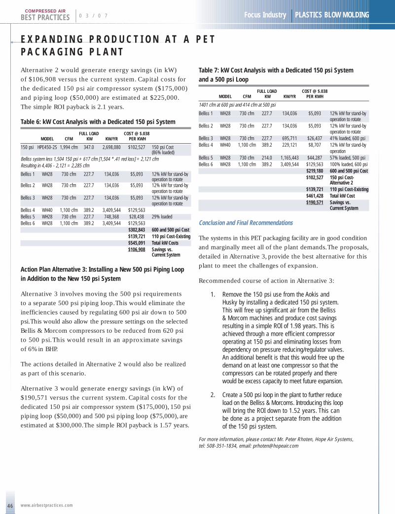
E X P A N D I N G P R O D U C T I O N A T A P E TP A C K A G I N G P L A N T
46
BEST PRACTICES | 0 3 / 0 7 Focus Industry | PLASTICS BLOW MOLDING
www.airbestpract ices.com
COMPRESSED AIR
Alternative 2 would generate energy savings (in kW)
of $106,908 versus the current system. Capital costs for
the dedicated 150 psi air compressor system ($175,000)
and piping loop ($50,000) are estimated at $225,000.
The simple ROI payback is 2.1 years.
Table 6: kW Cost Analysis with a Dedicated 150 psi System
FULL LOAD COST @ $.038MODEL CFM KW KW/YR PER KWH
150 psi HPE450-2S 1,994 cfm 347.0 2,698,080 $102,527 150 psi Cost (86% loaded)
Belliss system less 1,504 150 psi + 617 cfm [1,504 * .41 red loss] = 2,121 cfmResulting in 4,406 - 2,121 = 2,285 cfm
Belliss 1 WH28 730 cfm 227.7 134,036 $5,093 12% kW for stand-byoperation to rotate
Belliss 2 WH28 730 cfm 227.7 134,036 $5,093 12% kW for stand-by operation to rotate
Belliss 3 WH28 730 cfm 227.7 134,036 $5,093 12% kW for stand-byoperation to rotate
Belliss 4 WH40 1,100 cfm 389.2 3,409,544 $129,563Belliss 5 WH28 730 cfm 227.7 748,368 $28,438 29% loadedBelliss 6 WH28 1,100 cfm 389.2 3,409,544 $129,563
$302,843 600 and 500 psi Cost$139,721 110 psi Cost-Existing$545,091 Total kW Costs$106,908 Savings vs.
Current System
Action Plan Alternative 3: Installing a New 500 psi Piping Loop in Addition to the New 150 psi System
Alternative 3 involves moving the 500 psi requirements
to a separate 500 psi piping loop.This would eliminate the
inefficiencies caused by regulating 600 psi air down to 500
psi.This would also allow the pressure settings on the selected
Bellis & Morcom compressors to be reduced from 620 psi
to 500 psi.This would result in an approximate savings
of 6% in BHP.
The actions detailed in Alternative 2 would also be realized
as part of this scenario.
Alternative 3 would generate energy savings (in kW) of
$190,571 versus the current system. Capital costs for the
dedicated 150 psi air compressor system ($175,000), 150 psi
piping loop ($50,000) and 500 psi piping loop ($75,000), are
estimated at $300,000.The simple ROI payback is 1.57 years.
Table 7: kW Cost Analysis with a Dedicated 150 psi System and a 500 psi Loop
FULL LOAD COST @ $.038 MODEL CFM KW KW/YR PER KWH
1401 cfm at 600 psi and 414 cfm at 500 psi
Belliss 1 WH28 730 cfm 227.7 134,036 $5,093 12% kW for stand-byoperation to rotate
Belliss 2 WH28 730 cfm 227.7 134,036 $5,093 12% kW for stand-by operation to rotate
Belliss 3 WH28 730 cfm 227.7 695,711 $26,437 41% loaded, 600 psiBelliss 4 WH40 1,100 cfm 389.2 229,121 $8,707 12% kW for stand-by
operationBelliss 5 WH28 730 cfm 214.0 1,165,443 $44,287 57% loaded, 500 psiBelliss 6 WH28 1,100 cfm 389.2 3,409,544 $129,563 100% loaded, 600 psi
$219,180 600 and 500 psi Cost$102,527 150 psi Cost-
Alternative 2$139,721 110 psi Cost-Existing$461,428 Total kW Cost$190,571 Savings vs.
Current System
Conclusion and Final Recommendations
The systems in this PET packaging facility are in good condition
and marginally meet all of the plant demands.The proposals,
detailed in Alternative 3, provide the best alternative for this
plant to meet the challenges of expansion.
Recommended course of action in Alternative 3:
1. Remove the 150 psi use from the Aokis andHusky by installing a dedicated 150 psi system.This will free up significant air from the Belliss & Morcom machines and produce cost savingsresulting in a simple ROI of 1.98 years. This isachieved through a more efficient compressoroperating at 150 psi and eliminating losses fromdependency on pressure reducing/regulator valves.An additional benefit is that this would free up thedemand on at least one compressor so that thecompressors can be rotated properly and therewould be excess capacity to meet future expansion.
2. Create a 500 psi loop in the plant to further reduceload on the Belliss & Morcoms. Introducing this loopwill bring the ROI down to 1.52 years. This can be done as a project separate from the addition of the 150 psi system.
For more information, please contact Mr. Peter Rhoten, Hope Air Systems, tel: 508-351-1834, email: [email protected]

47
Compressed Air Industry | PLASTICS BLOW MOLDING 0 3 / 0 7 | BEST PRACTICESCOMPRESSED AIR
www.airbestpract ices.com
INDUSTRY NEWSPress Releases
BOURNE, MA, January 16, 2007 — Onset Computer Corporation, a leading
supplier of battery-powered data loggers, today announced the availability
of its 2007 Indoor Monitoring product catalog.
The catalog offers product descriptions, specifications and prices for a full line
of PC and Mac-based HOBO® data loggers for indoor monitoring applications.
A number of new hardware and software products are highlighted, including
Onset’s new HOBO Energy Logger Pro for energy monitoring and new alarm
software that provides real-time notification of environmental conditions
via email, pager and text messaging.
To receive a copy of the catalog, please visit
http://www.onsetcomp.com or call 1-800-LOGGERS.
About Onset Onset Computer Corporation has been producing small, inexpensive,battery-powered data loggers and embedded controllers since 1981, and has sold more than 1,000,000 loggers that are used throughout the world by more than 50,000 customers. The company manufactures a broad range of data logger and weather station products that are usedto measure temperature, humidity, light intensity, voltage and a broadrange of other parameters. Onset products are used in a wide range of research, commercial, industrial and educational applications.
MEDIA CONTACTEvan Lubofsky, Public Relations Manager Onset Computer CorporationTel. [email protected]
READER CONTACTOnset Computer Corporationwww.onsetcomp.com1-800-564-4377 / 508-759-9500Fax: [email protected]
O N S E T C O M P U T E R C O R P O R A T I O NA N N O U N C E S 2 0 0 7 P R O D U C T C A T A L O G
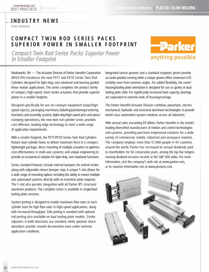
I N D U S T R Y N E W SPress Releases
48
BEST PRACTICES | 0 3 / 0 7 Compressed Air Industry | PLASTICS BLOW MOLDING
www.airbestpract ices.com
COMPRESSED AIR
Wadsworth, OH — The Actuator Division of Parker Hannifin Corporation(NYSE:PH) introduces the new P5TT and P5TD Series Twin RodCylinders designed for light-duty, non-rotational and bearing-guidedlinear motion applications. The series completes the product family of compact, high-speed, short-stroke actuators that provide superiorpower in a smaller footprint.
Designed specifically for use on conveyor equipment (stops/high-speed rejects), packaging machinery (labeling/positioning/centeringfunctions) and assembly systems (light-duty/high-speed pick-and-place/clamping operations), the new twin rod cylinder series provides cost-effective, leading-edge technology to meet a wide range of application requirements.
With a smaller footprint, the P5TT/P5TD Series Twin Rod Cylindersfeature dual-cylinder bores to deliver maximum force in a compact,lightweight package; direct mounting of multiple actuators to optimizecost-effectiveness in multi-axis systems; and unique engineering toprovide an economical solution for light-duty, non-rotational functions.
Series standard features include internal bumpers for extend strokealong with adjustable retract bumper stop. A unique T-slot allows fora wide range of mounting options including the ability to mount multiple-axis automated systems directly with no transition plate required.The T-slot also permits integration with all Parker IPS structuralaluminum products. The complete series is available in single/dualtooling plate versions.
System porting is designed to enable maximum flow rates to eachcylinder bore for high flow rates in high-speed applications, alongwith increased throughput. Side porting is standard with optional rod porting also available on dual tooling plate models. Strokeadjusters in both directions are standard, while optional shockabsorbers provide smooth deceleration even under extreme application conditions.
Integrated sensor grooves and a standard magnetic piston provideaccurate position sensing while a unique groove offers maximum LEDvisibility even from extreme angles. For added flexibility, the series’housing/tooling plate orientation is designed for use as gantry or dualtooling plate slide. For significantly increased load capacity, bearingsare separated to extreme ends of housing/carriage.
The Parker Hannifin Actuator Division combines pneumatic, electro-mechanical, hydraulic and structural aluminum technologies to provideworld-class automation system solutions across all industries.
With annual sales exceeding $9 billion, Parker Hannifin is the world’sleading diversified manufacturer of motion and control technologiesand systems, providing precision-engineered solutions for a widevariety of commercial, mobile, industrial and aerospace markets.The company employs more than 57,000 people in 43 countriesaround the world. Parker has increased its annual dividends paid to shareholders for 50 consecutive years, among the top five longest-running dividend-increase records in the S&P 500 index. For moreinformation, visit the company’s web site at www.parker.com,or its investor information site at www.phstock.com.
C O M P A C T T W I N R O D S E R I E S P A C K SS U P E R I O R P O W E R I N S M A L L E R F O O T P R I N T
Compact Twin Rod Series Packs Superior Power in Smaller Footprint
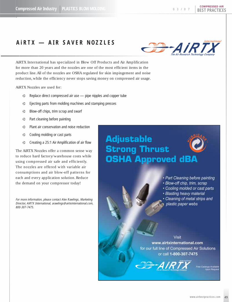
Compressed Air Industry | PLASTICS BLOW MOLDING 0 3 / 0 7 | BEST PRACTICESCOMPRESSED AIR
AiRTX International has specialized in Blow Off Products and Air Amplification
for more than 20 years and the nozzles are one of the most efficient items in the
product line.All of the nozzles are OSHA regulated for skin impingement and noise
reduction, while the efficiency never stops saving money on compressed air usage.
AiRTX Nozzles are used for:
p Replace direct compressed air use — pipe nipples and copper tube
p Ejecting parts from molding machines and stamping presses
p Blow-off chips, trim scrap and swarf
p Part cleaning before painting
p Plant air conservation and noise reduction
p Cooling molding or cast parts
p Creating a 25:1 Air Amplification of air flow
The AiRTX Nozzles offer a common sense way
to reduce hard factory/warehouse costs while
using compressed air safe and efficiently.
The nozzles are offered with variable air
consumptions and air blow-off patterns for
each and every application solution. Reduce
the demand on your compressor today!
For more information, please contact Alex Rawlings, MarketingDirector, AiRTX International, [email protected],800-307-7475.
A i R T X — A I R S A V E R N O Z Z L E S
49www.airbestpract ices.com
50
BEST PRACTICES | 0 3 / 0 7 Focus Industry | PLASTICS BLOW MOLDING
www.airbestpract ices.com
COMPRESSED AIRCompressed Air Industry | PLASTICS BLOW MOLDING
GRS · GRS FLUID HANDLINGNATIONAL MARKETING MANAGER — NORTHEAST/EAST U.S.
Sick of your boss? We can help! We are working on a search for a client, searching
for a National Marketing Manager who can lead a staff to great things. This position
will be responsible for total marketing of products, and be located in the Northeast/
East U.S. For an experienced candidate, direct reports will come not just from sales,
but from application and production.
Requirements:
• A technical background in marketing, with some experience
in the marketing of pump/compressor products and systems
• A Bachelors degree is required
• Experience working with customers, salesmen, C-level executives
and engineers
• An excitement about work and a positive attitude that leads to success
For someone with good leadership experience and a history of success in the
pump/vacuum/compressed air marketplace, this position offers a chance to be a
leader. With direct reports, personnel responsibilities and a role that reports directly
to the president — success in this role means visibility in the industry. If you are
someone who can succeed in a position like this, please send an e-mail to Mike Lee
For more information on these positions, any other positions we are working on or to
learn more about GRS and GRS Fluid Handling’s recruiting services, please send an e-mail
to us at [email protected].
6690 Beta Drive • Mayfield Village, OH • (440) 684-6150 • [email protected]
www.grsfluidhandling.com
Compressed Air Best Practices
JOB MARKETADVERTISING RATES
MAGAZINE ADSFor smaller classified-type ads use the following rates
per column inch:
1x per year: $94.00*per column inch
3x per year: $90.00* (i.e., this is a 10 col.inch, reversed ad)
12x per year: $84.00* *reversed ads = 1.5x normal price
Add $50.00 to post the job opening on
www.airbestpractices.com when you purchase an
ad in the magazine
Contact Patricia Smith for 4-color full page, 1/2 page
and 1/3 page ad rates
ONLINE ONLY ADSEach job posting is up on
the site for 60 days. Postings can be purchased in bulk
quantities per the rates below.The customer has 12 months
to put the postings on the site.After 12 months, any unusedpostings will be charged at
the minimum quantity.
Small Price per Bulk Price perQty. Posting Qty. Posting
1 $250 5-9 $1852 230 10-24 1703 210 25-49 1504 195 50+ 135
[email protected], tel: 251-510-2598
J o b O p e n i n g s i n t h e C o m p r e s s e d A i r I n d u s t r y
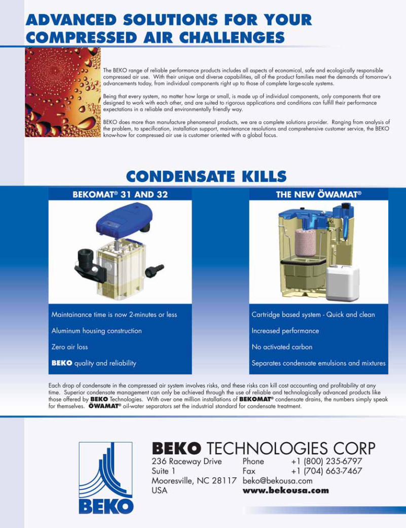

Consu l t i ng Se r v i c es • Compresso r P roduc t s • C lean A i r Tr ea tmen t P roduc t s • Con t ro l P roduc t s
COMPRESSORS
Kaeser Compressors, Inc., P.O. Box 946, Fredericksburg, VA 22404 USA � Tel: (800) 777-7873 � Fax: (540) 898-5520Sigma Profile and Built for a lifetime are trademarks of Kaeser Compressors, Inc. ©2007 Kaeser Compressors, Inc.
Taking efficiency to new heights.
Kaeser SFC compressors:
In the drive to save energy costs by precisely matching air production
to air demand, Kaeser’s Sigma Frequency Control compressors are the
most energy-efficient variable speed, single-stage compressors you can
find. The competition simply can’t compare in performance or quality.
Kaeser SFC compressors offer a wider range of operation, from 20%
partial load to 100% full load. Plus, our oversized Sigma Profile TM airend
rotates at lower speeds for greater output while consuming less energy.
With near-unity power factory, built-in phase protection, and superior
pressure control, our SFCs are built for a lifetime! And, since we offer
them in the widest range of sizes – most with integral dryer options –
we have just the right model for your needs. Of course, the best way to
appreciate the superior engineering of Kaeser SFC compressors is to
see them in operation, so call 800-777-7873 to find one near you.