air permit technical guidance for chemical sources ... permit technical guidance for chemical...
TRANSCRIPT
TCEQ (APDG 6422v2, Revised 06/2018) Page i
Air Permit Technical Guidance for Chemical Sources
Fugitive Guidance
APDG 6422
Air Permits Division Texas Commission on Environmental Quality
June 2018

TCEQ- (APDG 6422v2, Revised 06/18) Page ii
Technical Disclaimer
This Package Is Intended For Instructional Use Only
References to abatement technologies are not intended to represent minimum or maximum levels of BACT. Determinations of BACT are made on a case-by-case basis as part of the New Source Review of permit applications. BACT determinations are always subject to adjustment in consideration of specific process requirements air quality concerns, and recent developments in abatement technology. Additionally, specific health effects concerns may indicate stricter abatement than required by the BACT determination.
The represented calculation methods are intended as an aid in the completion of an acceptable submittal; alternative calculation methods may be equally acceptable if they are based upon, and adequately demonstrate, sound engineering assumptions or data.
The regulations discussed or referenced in this document are applicable as of the publication date of this package, but are subject to revision during the application preparation and review period. It is the responsibility of applicants to remain abreast of regulation developments that may affect their industries.
Examples of boilerplate special conditions are available on the TCEQ Internet site. Special Conditions included in an actual permit are written by the permit reviewer to address specific permit requirements and operating conditions.
The electronic version of this document may contain attachments/forms/tables that can be obtained electronically elsewhere on the TCEQ Internet site.

TCEQ- (APDG 6422v2, Revised 06/18) Page 1 of 33
Equipment Leak Fugitives
This document is intended to aid the permit applicant in the preparation of a technically complete permit application. The equipment leak fugitive emissions discussed in this guidance document package refer to the emissions from piping components and associated equipment including, but not limited to valves, connectors, pumps, agitators, compressor seals, relief valves, process drains, and open-ended lines. When components contain material that has the potential to act as an air pollutant, emissions of this potential pollutant must be estimated. Uncaptured emissions emanating from other sources such as cooling towers, oil/water separators, material stockpiles, and loading operations are not addressed in this document. This document discusses methods for calculating emissions from fugitive components, TCEQ inspection programs for reducing emissions from fugitive components, control technology, netting, and applicable regulations. This document does not address emissions from maintenance, start-up and shutdown (MSS). For guidance on MSS emissions from fugitive components refer to the MSS guidance. For more information on MSS please refer to www.tceq.texas.gov/assets/public/permitting/air/Guidance/NewSourceReview/mss/mss-guidance.pdf
The TCEQ encourages pollution prevention, specifically source reduction, as a means of eliminating or reducing air emissions from industrial processes. The applicant should consider opportunities to prevent or reduce the generation of emissions at the source whenever possible through methods such as product substitutions, process changes, or training. Considering such opportunities prior to designing or applying “end-of-pipe” controls can not only reduce the generation of emissions, but may also provide potential reductions in subsequent control design requirements (e.g., size) and costs.
Fugitive emission rates are estimated by counting the number of fugitive components, applying appropriate emission factors based on component type and service, and utilizing a reduction factor based on a monitoring program. Each of these elements is discussed in the following sections. Table 33 in attachment C has been developed to assist the applicant to report complete and accurate information needed to evaluate fugitive emissions represented on an application. This includes the number of fugitive components, component type, service type, industry type and pollutant type. This table also assists the permit reviewers to check the fugitive emission calculations more efficiently and consistently. Therefore, applicants are encouraged to complete this table and include it in their application.

Section I: Quantifying Uncontrolled Emissions
Uncontrolled fugitive emissions are quantified by the number and type of components and an emission rate factor for each component type. Fugitive emission factors have been established by case studies of chemical plants, oil and gas facilities, refineries, gasoline marketing terminals, and other industries, as discussed later in this section. An average leak factor is used to determine what the fugitive emission rate is for an area, a facility, or an entire plant.
Estimates are based on the assumption that all piping components are leaking vapors into the atmosphere at all times. For purposes of permitting, the emission rate is based on the number of components of a specific type in a defined area multiplied by the appropriate fugitive emission factor. The emission rate for a component type must also be speciated for the compounds found within the process unit or area. All components must be included in the emission estimate, even components that are exempt from monitoring, unless they are excluded from emission calculations as described under Additional Information.
The specific factors currently approved for use by the TCEQ are located in Appendix A and can also be found in the web page for Equipment Leak Fugitives, www.tceq.texas.gov/permitting/air/guidance/newsourcereview/fugitives/nsr_fac_eqfug.html. Sets of factors have been established for several industries, as described below. Emission rate estimates must be calculated using the appropriate set of factors. If factors are not established for a particular industry, the SOCMI factors without ethylene may be used, or the TCEQ Air Permits Division (APD) can be contacted for guidance.
Fugitive Emission Factor The Fugitive Emission Factor (FEF) is an average leak factor determined from data collected during industry case studies. The FEF is in units of pounds per hour per component (lb/hr/component). The following equation is used to estimate uncontrolled fugitive emissions for each type of component:
(FEF) × (# of components) = uncontrolled fugitive emission rate
There are three main criteria in choosing the correct FEF: • Component type• Service• Industry or pollutant type
These criteria are explained in more detail in the sections that follow.
Component Type The main component types considered are:
• Valves• Pumps• Flanges/connectors• Compressors• Relief valves• Open-ended lines• Process drains.
There may be other components found within a specific industry. For instance, in oil and gas production operations, other components may include diaphragms, dump arms, hatches, instruments, meters, and polished rods. For more information, please see Appendix A, Table II, footnote 10.
Some components are exempt from monitoring requirements based on size, physical location at a facility, VOC content, or low vapor pressure service. Emissions from these components must be calculated and included in the estimated fugitive emission rate regardless of any monitoring exemptions. In addition, certain difficult-to-monitor (DTM) and unsafe-to-monitor components, as defined in 30 Texas Administrative Code (TAC) Chapter 115, §115.352(7) and §115.354(1)(C) are exempt from monitoring requirements but the uncontrolled emissions must still be calculated. TCEQ-(APDG 6422v2, Revised 06/18) Page 2 of 33

TCEQ- (APDG 6422v2, Revised 06/18) Page 3 of 33
Factors have not been developed for certain types of piping components. In order to ensure consistency, the TCEQ has reviewed factors for components with similar characteristics and designated the following guidelines for calculating emissions from these components:
• Emissions from screwed fittings should be estimated in the same manner as connectors.• Emissions from liquid relief valves should be estimated in the same manner as light liquid valves. This
addresses only the emissions resulting from the liquid relief valve reseating. It does not address therelease itself which is an emission event.
• Emissions from agitators should be estimated in the same manner as light liquid pumps.• Tubing size lines (flexible lines less than or equal to 0.5 inches in diameter) and equipment do not need
to be quantified, unless the lines or equipment are subject to monitoring by any federal or stateregulation.
A complete list of component types can be found in Tables I and II in Appendix A.
Service The service designates the type of specific fluid handled by the component of concern. For most industries, these fluids include gas/vapor, light liquid, and heavy liquid. Oil and gas production operation factors include gas, water/light oil, light oil, and heavy oil. For industries other than oil and gas production sites, heavy liquids have vapor pressures of 0.044 pound per square inch absolute (psia) or less and light liquids have vapor pressures higher than 0.044 psia at 68°F. Gas/vapor factors are used for components in gas service at the operational conditions.
Industry or pollutant type The fugitive factor type indicates a set of factors that have been defined and approved for a specific industry.
For Table I, the fugitive factor types are: • Synthetic Organic Chemical Manufacturing Industry (SOCMI) Average• SOCMI Without Ethylene (C2)• SOCMI With Ethylene (C2)• SOCMI Non-Leaker.
For Table II, the fugitive factor types are: • Ethylene Oxide• Phosgene• Butadiene• Petroleum Marketing Terminal• Oil and Gas Production Operations• Refinery.
Specialty FEFs Specialty FEFs are industry or pollutant specific factors with specified Leak Detection and Repair (LDAR) program credits inherent within the factor. If an applicant uses Specialty FEFs, they are committed to using the associated LDAR program. Because LDAR program credits for those specialty factors are embedded within the specialty factors, the applicant cannot receive additional credits for using that LDAR program.
The SOCMI Non-Leaker FEFs in Table I, and the Ethylene Oxide, Phosgene, Butadiene, and Petroleum Marketing Terminal FEFs in Table II are considered Specialty FEFs. Applicants using the SOCMI Non-Leaker FEFs must employ LDAR program 28PI, endnote 3 in Table I. The ethylene oxide, phosgene, and butadiene factors can only be used with the specific LDAR programs defined in the associated footnotes in Table II. These factors will require additional permit conditions and can only be used for process lines that contain essentially pure compounds. Applicants using the Petroleum Marketing Terminal FEFs must employ LDAR program 28PET, endnote 5 and 6 in Table II. Refer to Section II for more detailed discussions on LDAR programs 28PI and 28PET.

Speciated Emissions If the chemical composition in a process unit is not 100% pure, a speciation, or breakdown of the different compounds, is necessary to determine the off-property impact for each different compound emitted from a fugitive source. This includes compounds other than VOCs such as inorganic compounds, exempt solvents, and inerts.
For example, if a process unit contains 80% toluene and 20% ethylene, the emission rate would need to reflect the estimated quantity of emissions for each compound. Multiplying the emission rate by the weight percent of each compound yields the specific emission rate for that compound. If the weight percent of a particular compound varies from one process stream to another, then the fugitive emission rate for each area should be calculated separately, multiplied by the appropriate weight percent, and then totaled. The permit applicant may also group different streams together and determine the maximum percentage of each compound for that group. When using this method, the speciated emissions may exceed the total VOC emissions. The total emission rate of each individual chemical should be submitted with the permit application. Please see Table VII in Appendix A for an example of speciation calculations. Note that further speciation is not necessary for mixtures with defined ESLs, for example crude oil and gasoline. For complex mixtures with low volatility consult your permit reviewer for speciation requirements. In many cases, similar compounds can be grouped together with assignment of an appropriately conservative ESL.
Selecting Appropriate Factors for the Site
SOCMI Factors The SOCMI factors are generally used in chemical plants and in chemical process units that are located in a refinery (e.g., cumene unit). The original SOCMI average factors were developed to represent fugitive emission rates from all chemical plants. The SOCMI average factors are found in the Environmental Protection Agency’s (EPA) document EPA 453/R-95-017, “Protocol for Equipment Leak Emission Estimates,” page 2-12, available at the EPA’s Web site at www3.epa.gov/ttnchie1/efdocs/equiplks.pdf. From these factors, the TCEQ further derived two additional sets of factors: “SOCMI with ethylene” to be used for components where the ethylene concentration is greater than 85% by weight; and “SOCMI without ethylene” to be used where the ethylene concentration is less than 11%. For streams where the ethylene concentration is between 11% - 85%, the SOCMI average factors should be applied. For components in service where the material has a vapor pressure between 0.0147 psia and 0.147 psia, fugitives may be estimated with the SOCMI Non-Leaker factors. The SOCMI Non-Leaker factors were developed from test data where no leaking emissions occurred above 10,000 parts per million per volume (ppmv); therefore, using the Non-Leaker factors assumes that no leaks will occur over the 10,000 ppmv leak detection threshold.
Petroleum Marketing Terminal Factors In February of 1995, TCEQ approved the use of the Petroleum Marketing Terminal Factors found in EPA document EPA-453/R-95-017, page 2-14. These factors are used to estimate fugitive emissions from components at gasoline distribution facilities that are “one-step removed” from local gasoline stations and other end-users. Although gasoline distribution facilities may also handle jet fuel and diesel, gasoline is their primary product. In a memorandum dated December 5, 2005, TCEQ approved the use of these factors for Pipeline Breakout Stations for crude oil and fuel service (gasoline, diesel, and jet fuel). For more information, please see www.tceq.texas.gov/assets/public/permitting/air/memos/petroleum_marketing.pdf.
The PMT factors were designed to be used only at distribution and pipeline breakout stations handling only fuels or fuel-related products at a facility consisting only of storage tanks and truck loading facilities. Loading racks at chemical plants, large terminals for hire, and refineries may not use these factors. Terminals for hire are generally larger, more complex facilities that store a variety of liquid compounds, and may have additional operations such as marine loading. Also, even though a terminal for hire may initially store only fuels and fuel-related products, they might later receive authorization through permit by rule (PBR) to store other products. In limited circumstances, small terminals for hire may be allowed to use the PMT factors if they meet all of the following criteria: the site has less than 25 tanks, it is limited by permit to only store fuels and fuel-related products and is prohibited by permit condition or physical constraints from using PBR authorization to authorize handling of other compounds, and it loads only tank trucks (no marine loading). TCEQ-(APDG 6422v2, Revised 06/18) Page 4 of 33

TCEQ-(APDG 6422v2, Revised 06/18) Page 5 of 33
Use of the PMT factors is accompanied by a physical inspection LDAR program performed on a monthly basis as specified in the 28PET permit special conditions. The petroleum marketing terminal factors include the appropriate reduction credit for the physical inspection; therefore, no additional reductions to the factors are necessary. The decision to require a physical inspection program instead of instrument monitoring was based on the EPA/American Petroleum Institute (API) bagging study of various gasoline distribution facilities employing a variety of LDAR programs. The results of the study indicated that little or no improvement in fugitive emission control was achieved when an instrument was used to detect leaks at this type of facility.
Oil and Gas Production Operations Factors The Oil and Gas Production Operations factors are based on equipment leak emissions data from the oil and gas production industry that was gathered by API and evaluated by the EPA. There are four equipment service categories covered by the Oil and Gas Production factors:
1. Gas Factors,2. Heavy Oil (< 20° API gravity),3. Light Oil (> 20° API gravity), and4. Water/Light Oil (water streams in light oil service with a water content between 50% and 99% by
weight).
The gas factors estimate total hydrocarbon emissions; therefore, the calculated emission rates must be multiplied by the VOC weight percent, (i.e., methane and ethane are excluded), in the gas stream to get a total VOC rate for permitting purposes. The Oil and Gas Production Operations gas factors replace the Gas Plant Fugitive Factors from the EPA protocol document (EPA-453/R-93-026).
Operators of crude oil pipeline facilities which handle weathered or “dead” crude may use the Oil and Gas Heavy Oil (< 20° API gravity) factors to estimate fugitive emissions. This decision was based upon studies at tank batteries and other upstream facilities that demonstrated weathered crude is free of the entrained gases and easily volatilized light ends.
Refinery Factors Refinery factors are used when estimating fugitive emissions in a petroleum refinery process unit. A chemical process, such as a cumene production unit, may be located in a refining facility; however, because it is not considered a refinery process, the refinery factors should not be used to calculate that specific unit's fugitive emissions. Refinery factors are given in the EPA document, EPA 453/R-95-017, page 2-13, available at the EPA’s Web site at www3.epa.gov/ttnchie1/efdocs/equiplks.pdf.
Additional Information This subsection discusses particular instances in regard to quantifying uncontrolled fugitive emissions including:
• When Fugitive Emissions Do Not Need to Be Quantified• Fugitive Emissions from Select Odorous and Inorganic Compounds• Operating Hours When Quantifying Fugitive Emissions• Correlation Equations and Plant-Specific Factors• Quantifying Fugitive Emissions from Process Drains• Maximum Allowable Emission Rates Table (MAERT) Footnote Clarification
When Fugitive Emissions Do Not Need to Be Quantified Emissions from certain components are expected to be so low that emissions from them do not need to be quantified. These include the following:
• Tubing size lines (flexible lines less than or equal to 0.5 inches in diameter) and equipment, unless thelines or equipment are subject to monitoring by any federal or state regulation. (As of August 2017, nocurrent state regulations require that tubing less than 0.5 inches be monitored).
• Non-piping type fittings (swedge lock or ferrule fittings).• Streams where the operating pressure is at least 0.7 psi below ambient pressure.• VOC emissions from mixtures in streams where the VOC has an aggregate partial pressure of less
than 0.002 psi at 68°Fahrenheit.
TCEQ-(APDG 6422v2, Revised 06/18) Page 6 of 33
• Anything that is not considered an air contaminant (i.e. water vapor and nitrogen).• Nitrogen lines (does not include lines with nitrogen that has been used as a sweep gas).• Steam lines (non-contact).• Components containing only noble gases, inerts such as CO2 and water or air contaminants not
typically listed on a MAERT such as methane, ethane, and Freon.• Storage tank conservation vents.
In other cases, emissions must be quantified even though the components may be exempt from monitoring requirements or qualify for reduced monitoring. These include the following:
• Unsafe-to-monitor components that qualify for reduced monitoring.• Difficult-to-monitor components that qualify for reduced monitoring.• Equipment in VOC service only during startup and shutdown, excluding startup and shutdown between
batches of the same campaign for a batch process.• Any pressure relief device that is routed to a process or fuel gas system or equipped with a closed vent
system capable of capturing and transporting leakage through the pressure relief device to a controldevice (quantify emissions from control device).
• Wastewater lines, pipeline quality sweet natural gas lines, and other lines that may be exempt frommonitoring based on the weight percent VOC in the stream.
• Equipment that is exempt from monitoring under the applicable LDAR program (for example, where theVOC has an aggregate partial pressure or vapor pressure of less than 0.044 pounds per square inch,absolute (psia) at 68°F).
Fugitive Emissions from Inorganic Compounds For inorganic compounds such as chlorine (Cl2), ammonia (NH3), hydrogen sulfide (H2S), hydrogen fluoride (HF), and hydrogen cyanide (HCN), fugitive emissions are calculated in the same manner as VOC fugitive emissions. Although the VOC emission factors were not developed specifically for use with these compounds, they are presently recommended for estimating their fugitive emissions.
Operating Hours When Quantifying Fugitive Emissions Fugitive emission factors are independent of process-unit throughput and therefore fugitives are assumed to occur if there is material in the line, regardless of the activity of the process. Therefore, the hours in service for all streams should always be 8,760 hours annually, regardless of process downtime. Any exception to this service time would result in a permit condition requiring the lines to be purged during process downtime.
Correlation Equations and Plant-Specific Factors The use of various correlation equations developed by EPA for estimating fugitive emissions is not accepted for permitting purposes although they can be used for estimating actual emissions for emission inventory purposes.
Emission factors developed for individual facilities are also not accepted for permitting purposes, unless prior approval has been obtained before the application is submitted. TCEQ does not have the resources to evaluate studies for individual facilities or companies during application review. Emission factors developed for individual facilities require additional discussions, development of sampling protocols, and analysis of results prior to their use in a submitted permitting application.
Quantifying Fugitive Emissions from Process Drains The refinery factor for fugitive emissions from process drains may be applied to any process drain regardless of facility or industry type.
MAERT Footnote Clarification In the past, some permits were issued with a footnote on the MAERT indicating that “Fugitive emissions are an estimate only and should not be considered as a maximum allowable emission rate.” The footnote language has been revised to indicate that the “Emission rate is an estimate and is enforceable through compliance with the applicable special condition(s) and permit application representations.” The newer language more clearly states the intent of the earlier language. The intent of the “new” language is to ensure that the permit holder is in compliance with their permit representations and LDAR programs. Although fugitive emission rates are
TCEQ-(APDG 6422v2, Revised 06/18) Page 7 of 33
“estimates” they are used in determining applicability of Title V and major new source review. It is not likely that a regulated entity would have measured concentrations that would lead to emission rates calculated through correlation equations that would exceed the MAERT limits, unless the number of components was greater than the number on which the MAERT limit was based. In this case, the older footnote language could result in enforcement action against the regulated entity for exceeding the number of components represented.
Section II - Fugitive Emission Reduction Options
Fugitive emission rates can be reduced by two methods: leak detection and repair (LDAR) programs and equipment specification. Pollution prevention should be considered when designing a process unit to minimize the number of piping components. Certain types of equipment have lower emissions by design as outlined in the design options section.
LDAR Programs
LDAR programs are used to inspect fugitive components to identify leaks either by using instruments or in limited cases, by physical inspections. Leaks identified by the inspections are then repaired within a specified time period, thus reducing the emissions. When these programs are in place, estimated fugitive emissions can be reduced using the emission control credits according to Table V, in Appendix A. These credits can only be given in cases where the components are actually inspected and for components for which the LDAR program could result in emission reductions.
LDAR programs can be grouped into two categories:
• Instrument monitoring, and• Physical inspection.
Instrument Monitoring LDAR programs can be differentiated by four key criteria as shown below and also in Appendix A Table III:
• Leak definition: The leak definition is the monitored concentration of an air contaminant, defined inparts per million by volume (ppmv), that identifies a leaking component needing repair. The mostcommon levels used for pumps are 10,000 ppmv; 2,000 ppmv; and 500 ppmv and for othercomponents are 10,000 ppmv and 500 ppmv.
• Monitoring frequency: The monitoring frequency varies depending on the component types and theLDAR program in place. Components typically must be monitored on a quarterly basis; however, someprograms allow facilities to skip monitoring periods when the percentage of leaking components ismaintained under a specified rate.
• Properties of the monitored compounds: Some LDAR programs define the components to bemonitored by the vapor pressure of the material in the component or the weight percent of VOC in thestream. Compounds must have sufficient VOC vapor pressure to register as a leak when dripping toqualify for an emission reduction credit for monitoring.
• Requirements for repair: Program repair requirements may be either directed or non-directedmaintenance. A directed maintenance program requires that a gas analyzer be used in conjunction withthe repair or maintenance of leaking components to assure that a minimum leak concentration isachieved. A non-directed maintenance program does not require the use of a gas analyzer duringrepair or maintenance of a leaking component. In either case, if a replacement is required to fix aleaking component, the replaced component should be re-monitored within 15 days to confirm that therepair was successful.
Each of the instrument monitoring programs is outlined in Table III of Appendix A. LDAR credits can only be given in cases where the components are actually inspected and only for components for which the LDAR program could result in emission reductions. Control credits do not apply to components that are designated as difficult or unsafe-to-monitor, unless these components are monitored. For example, if difficult-to-monitor components are monitored annually at 500 ppmv, then a 75% reduction credit can be applied as it is for annual connector monitoring per 28 CNTA.

Some LDAR programs allow reduced monitoring frequency if the numbers of leaking components detected are below a specific percentage. In these cases the components using the skip options would continue to qualify for the same reduction credit.
The credits, or control efficiencies, associated with each program are listed in Table V of Appendix A. Summaries of the programs are shown below:
28M, 28RCT, 28VHP, 28MID and 28LAER
• These are the most common LDAR programs. These are differentiated by leak definition, vaporpressure, and directed versus non-directed maintenance as detailed in Table III.
• The 28LAER LDAR program is used to control fugitive emissions that are part of a nonattainmentpermit. For facilities that are not subject to a nonattainment permit, the same emission reductions maybe attained by implementing the 28MID program in conjunction with the 28CNTQ LDAR program forconnectors and 28PI for components in heavy liquid service.
• In an effort to keep the permit special conditions for LDAR programs as concise as possible, theprocedures to calculate emissions from leaking components to justify delay of repair are not outlined inthe 28 series LDAR programs; instead they reference 30 TAC Chapter 115, Subchapter H, Division 3.The 28 series LDAR programs also use the 30 TAC Chapter 115, Subchapter D, Division 3, §115.352definition for difficult-to-monitor valves.
• When initial monitoring is required for existing components that have a change of service and are nowrequired to be monitored quarterly, these components are normally associated with a specific portion ofa process line or a plant. Most companies have an ongoing LDAR monitoring program in which amonitoring team works its way through the various sections of the plant by adhering to a schedule thatwill insure that every component is monitored once each quarter. It is conceivable that a component willre-enter service after the monitoring team has departed that portion of the plant. In that particular case,it is acceptable that this particular component is not monitored until the monitoring team is scheduled tomonitor that portion of the plant again, as long as it is monitored within the next quarter.
28CNTQ and 28CNTA
• These are LDAR monitoring programs for connectors that can be added to weekly inspections toincrease the reduction credit.
LDAR for Inorganic VOC Mixtures For inorganics in VOC mixtures that are monitored according to an LDAR program, the calculated uncontrolled emission rates can be reduced according to the credit allowed by the monitoring program. The emission rates of the inorganic compounds are determined by multiplying the total emission rate by the weight-percent of each individual compound present in the stream. Please see Table VII for an example.
Reduction Credit for Annual and Quarterly Connector Monitoring Annual instrument monitoring of connectors/flanges at a 500 ppmv leak detection limit may receive a 75% reduction credit at petroleum refineries and SOCMI facilities. This determination is based on information contained in the 1993 EPA document “Protocol for Equipment Leak Fugitives” and the results from monitoring data. The control effectiveness percentages given in the protocol document are based on the type of facility, monitored data, and the corresponding reduction in the percentage of leaking flanges. The lowest percent reduction was used to establish the appropriate reduction credit as it is preferable to allow a single reduction credit for both chemical facilities and refineries. Thus, the 75% reduction credit is suitable for use at both petroleum refineries and SOCMI facilities where the connectors/flanges are monitored annually at 500 ppmv. The 28CNTA LDAR program specifies the monitoring and recordkeeping necessary to receive the 75% reduction credit. This program may be used in conjunction with any of the other 28 series LDAR programs, except 28LAER, which already includes connector monitoring.
Quarterly instrument monitoring of connectors at a 500 ppmv leak detection limit may receive a 97% reduction credit. This credit is equivalent to that received by valves monitored at the same leak detection limit and frequency. The 28CNTQ LDAR program specifies the monitoring and recordkeeping necessary to receive the 97% reduction credit. This program may be used in conjunction with any of the other 28 series LDAR programs, except 28LAER, which already includes connector monitoring. TCEQ-(APDG 6422v2, Revised 06/18) Page 8 of 33

TCEQ-(APDG 6422v2, Revised 06/18) Page 9 of 33
Low Vapor Pressure Compounds Compounds with low vapor pressures can present a problem with instrument monitoring. No reduction credits are allowed for valves and pumps in heavy liquid service under any of the five 28 Series LDAR programs or 30 TAC Chapter 115 because components in heavy liquid service are not required to be monitored. An applicant may propose to monitor these components and take the appropriate reduction credits as noted in Table V, in Appendix A; however, the applicant must demonstrate that leaking components can be detected by implementing an instrument assisted fugitive monitoring program. For materials with vapor pressures below 0.147 psia, implementing a LDAR program with a 10,000 ppmv leak detection definition would be useless as leaking components may never be detected. For example, a component in heavy liquid service (vapor pressure < 0.044 psia) which is subject to a LDAR program with a leak definition of 10,000 ppmv would have a theoretical saturation concentration of 0.044/14.7 = 2990 ppmv. Depending on the instrument lower detection limit for the compounds being measured, this concentration may not be a measurable quantity; thus, it may not be possible to demonstrate an actual emission reduction via instrumental monitoring. These components would not get increased maintenance or reduced emission rates as a result of a LDAR Program with a 10,000-ppmv leak definition; therefore, these components cannot receive any reduction credit. To reduce these emissions, the applicant would have to commit to a 500 ppmv leak definition program.
For ultra-heavy liquids with vapor pressure less than 0.0147 psia at ambient temperature, emissions are calculated using the SOCMI without ethylene factors and the application of the 28 audio, visual and olfactory (28AVO) LDAR program reduction credits. Because the vapor pressure is so low, a dripping liquid leak found by visual inspection would have a similar concentration as the 500 ppmv leak rate that the 28AVO reduction credits are based upon. This estimate is more representative than the SOCMI factor alone because the SOCMI heavy liquid factor is overly conservative for these ultra-heavy liquids. Use of this estimation method requires the implementation of the 28 physical inspection (28PI) LDAR program as a minimum requirement. The weekly physical inspection for the dripping liquids is sufficient to control the air emissions and prevent the build-up of a liquid puddle which could become a wastewater permitting issue due to rain water runoff.
Phosgene, Butadiene, and Ethylene Oxide LDAR programs Specific factors have been developed for use with components in phosgene, butadiene, and ethylene oxide production facilities. These factors are used to estimate fugitive emissions from components in phosgene, butadiene, and ethylene oxide production facilities when monitored with the 28MID LDAR Program at the following leak definitions: Phosgene 50 ppmv Butadiene 100 ppmv Ethylene Oxide 500 ppmv
Note: the ethylene oxide connector factor does not include instrument monitoring. An additional reduction credit can be taken if connector monitoring is required.
TCEQ-(APDG 6422v2, Revised 06/18) Page 10 of 33
Physical Inspection Programs
Physical inspections are available for those compounds for which instrument monitoring is not appropriate and for heavy liquids below the vapor pressure thresholds of the various LDAR programs. Physical inspections rely primarily on the visual detection of dripping liquids. A few highly odorous compounds with extreme odor nuisance potential may utilize an audio, visual and olfactory program (28AVO) to reduce leaks; however, use of this program is restricted to the following approved compounds: chlorine, ammonia, hydrogen sulfide, hydrogen cyanide and mercaptans. Hydrogen fluoride fugitives are controlled visually by the use of HF detection paint and are also subject to the 28AVO LDAR program.
28PI Weekly physical inspection of all components for dripping liquids may be used when all components are in heavy liquid service for a 30% reduction credit. When components are in ultra-heavy liquid service (VP<0.0147-psia), 28PI may be used but the 28AVO credits may be employed. This program may also be used for insulated components that cannot be monitored with an instrument as long as a visual indication of a leak can be pin-pointed to the appropriate component and the insulation can be removed to repair the leak.
28PET Monthly physical inspection for dripping liquids may only be used in conjunction with the Petroleum Marketing Terminal factors for bulk gasoline terminals and pipeline breakout stations.
28 Audio, Visual and Olfactory (AVO) Inspection The 28AVO inspection program is a physical walk-through inspection every four hours with repair or containment of leak within one hour of detection and identification. This may only be used with certain compounds for which instrument monitoring is not available and which have sufficient odors to allow ready detection of leaks. It is approved for chlorine, ammonia, hydrogen sulfide, hydrogen fluoride, hydrogen cyanide, and mercaptans. Other odorous compounds may be considered with TCEQ management approval. If the predicted off-property impact of an inorganic/odorous compound is unacceptable, the applicant will be required to implement the 28AVO walk-through inspection. The inspection frequency given in the 28AVO condition may be reduced on a case-by-case basis, but may not be reduced to less than once a shift.
The 28AVO credit is based on type of component, not vapor pressure or service type. Fugitive emission rates controlled through the 28AVO inspection are determined as follows:
The total number of components in service of the compound in question should be multiplied by the appropriate “SOCMI without ethylene” emission factor regardless of industry type, as described in Section I. The 28AVO reduction credits found in Appendix A, Table V should then be applied to the uncontrolled inorganic, odorous compound emission rates.
If inorganic compounds are present in VOC mixtures and their maximum predicted off-property impacts are acceptable based on reduction credits from the VOC monitoring, separate 28AVO monitoring may not be required.
Equipment Credits
There are certain options that may be implemented in the design of a facility to reduce fugitive emissions. When calculating emission rates, various control credits may be applied to components in service as described below. Also, LDAR program monitoring for identified types of equipment is not required if 100% reduction credit is given. Remember that all fugitive components must be included in component counts, even if they are given 100% credit.
Relief Valves 100% control may be taken if one of the following conditions is met:
1. Relief valve vents are routed to an operating control device; or2. Relief valves are equipped with a rupture disc and pressure sensing device (between the valve and
disc) to monitor for disc integrity.
For new facilities, BACT guidelines generally require that all relief valves vent to a control device in order to control the releases. Releases may be vented to atmosphere if required for safety purposes and justified by applicant. If the relief valve is vented to the atmosphere it must be monitored regardless of accessibility unless each valve is equipped with a rupture disc upstream. A pressure gauge must also be installed between the relief valve and rupture disc to monitor disc integrity, and all leaking discs must be replaced at the earliest opportunity but no later than the next process shutdown.
Pumps Certain types of pumps are designed to be “leakless” and can be given 100% control credit. Any of the following designs are accepted as leakless pumps:
1. Canned Pumps,2. Magnetic Drive Pumps,3. Diaphragm Pumps,4. Double mechanical seals and the use of a barrier fluid at a higher pressure than the process, and5. Double mechanical seals and venting the barrier fluid seal pot to a control device.
Valves 100% control credit may be taken if one of the following conditions is met:
1. Use of bellows valves with bellows welded to both the bonnet and stem,2. Use of diaphragm-type valves, or3. Use of seal-welded, magnetically actuated, packless, hermetically sealed control valves.
Open-ended lines If an open-ended line is equipped with a cap, blind flange, plug, or a second valve, then a 100% control credit can be taken. The connector count is increased by the number of open-ended lines to account for the credit. Valves used in this manner are counted as connectors.
Connectors Connectors may receive 100% control credit if the connections are welded together around the circumference of the connection such that the flanges are no longer capable of being disassembled by simply removing the bolts.
Compressors Compressors must be designed to be entirely enclosed and must have the crankcase vented to a control device to be given 100% control.
Double Mechanical Seals Any component employing double mechanical seals may be given a 75% credit. If the seals are monitored, then use the appropriate monitoring credit. One hundred percent credit can be given if the barrier fluid seal pot is controlled or the barrier fluid is at a higher pressure than process pressure.
Process Drains Facilities subject to fugitive emission monitoring under 30 TAC §§115.324(1)(C) and 354(1)(A) are required to monitor process drains on an annual basis. A 75% reduction credit may be applied for annual monitoring of process drains at a leak threshold of 500 ppmv provided the drain is designed in such a manner that repairs to leaking drains can be achieved. For example, flushing a water seal on a leaking process drain would constitute repair, so a 75% reduction credit may be applied. Similarly, a 95% reduction credit can be applied for quarterly monitoring of drains if repairs to the leaking drains can be completed.
Design Options
There are certain options that may be incorporated into the design of a facility to minimize piping components, improve maintenance and/or reduce susceptibility to leaks. While some of these options may not result in reduction credits for fugitive emissions, they can result in lower maintenance costs and improved performance in some cases. TCEQ-(APDG 6422v2, Revised 06/18) Page 11 of 33

TCEQ-(APDG 6422v2, Revised 06/18) Page 12 of 33
Overall 1. Design equipment layout to minimize pipe run lengths and associated connectors.2. Minimize the use of valves and other components.3. Minimize the use of relief valves whenever possible.4. Optimize piping and component metallurgy for compatibility with process streams and/or physical
environment to reduce corrosion potential.
Pumps 1. Use of pressure transfer to eliminate the need for pumps.2. Use of submerged pumps which limit the exposure of potential leaks to the atmosphere.
Valves 1. Optimize length of time between leaks by using special packing sets and stringent adherence to
packing procedures.2. Use on-line direct injection repair equipment. However, this option may introduce an additional potential
leak path for the valve if corrosion occurs around the tap.
Connectors 1. Use of new technologies which have been deemed by the TCEQ to be equivalent to flanges.2. Eliminate the use of screwed fittings smaller than 2 inches in diameter.
Note: BACT for fugitives does not allow the use of screwed connections on lines greater than 2 inchesin diameter.
Compressors 1. Designs with lower leak potentials such as diaphragm compressors.2. Shaft seal design such as carbon rings, double mechanical seals or buffered seals.3. Design options such as internal balancing, double inlet or gland eductors.
Quantifying Fugitive Emission Reductions
Here are several important points to remember when calculating fugitive emission rates: 1. All components must be accounted for when estimating emission rates regardless of exemptions from
monitoring requirements except for the fugitive components that meet the one or more of the exclusionsspecified in “When Fugitive Emissions Do Not Need to Be Quantified,”.
2. Taking an emission reduction for monitoring implies that all of those components will be monitoredregardless of exemptions.
3. Difficult-to-monitor components and other unmonitored components must be clearly identified andseparated from monitored components when calculating emission rates.
4. All components given emission reduction credits for monitoring must be capable of having reducedemissions through the monitoring program, i.e., any components represented as being monitored musthave sufficient vapor pressure to allow the reduction.
5. Representations of emission reductions in a permit application will result in permit special conditionsrequiring monitoring for certain components based on the emission estimates.
6. The following connector monitoring can be applied in order to reduce emissions:• For a weekly walk-through inspection as required by an LDAR program, a 30% credit can be taken.• The 28CNT LDAR programs are used in addition to the other 28 series LDAR programs if
connector monitoring is required by special circumstances or to reduce emissions.• For annual instrument monitoring of connectors under the 28CNTA LDAR program, a 75% credit
may be taken.• For quarterly instrument monitoring of connectors under the 28CNTQ LDAR program, the valve
credit corresponding to the appropriate leak definition for the LDAR program may be appliedinstead of the 30% credit.
7. Emission calculations should include a component count for those components with 100% controlefficiency with a footnote describing the specific method of control.
TCEQ-(APDG 6422v2, Revised 06/18) Page 13 of 33
Please see Table VII in Appendix A for an example calculation of fugitive emissions from equipment leaks for a SOCMI facility using the 28VHP LDAR program.
Section III - Best Available Control Technology and Impacts Guidelines
An integral part of the permitting process is the determination of Best Available Control Technology (BACT) for all new and modified sources.. BACT guidelines are based on the fugitive emissions for the site, not the new emissions only. The project may have lower emissions than the tons per year at which an LDAR program is required but the total uncontrolled site emissions are used to determine which LDAR program meets BACT. For example: An existing site currently does not require the use of a monitoring program, based on current uncontrolled fugitive emission rates. An applicant proposes to install a new process unit, which by itself would not require monitoring. If the emissions from the new unit combined with emissions from the existing unit would trigger a requirement to apply a monitoring program as BACT, the new unit would be required to institute monitoring.
Please see the TCEQ website www.tceq.texas.gov/permitting/air/nav/air_bact_chemsource.html, for guidelines for determining BACT for process fugitive emissions when submitting a permit application.
The uncontrolled annual emission rate thresholds and corresponding LDAR programs given in the TCEQ website are guidelines only; a case-by-case review will be performed for all permit applications. Separate applicability determinations must also be made for 30 TAC Chapter 115, 40 CFR Part 60, 40 CFR Part 61, or 40 CFR Part 63 affected sources. A more stringent program may be required to reduce impacts.
The following practices are generally considered to be the minimum for BACT.
1. Construction of new and reworked piping, valves, pump systems, and compressor systems shallconform to applicable American National Standards Institute (ANSI), American Petroleum Institute(API), American Society of Mechanical Engineers (ASME), or equivalent codes based on the material.
2. New and reworked buried connectors shall be welded.3. To the extent that good engineering practice will permit, new and reworked valves and piping
connections shall be reasonably accessible for leak checking during plant operation.4. Damaged, leaking, or severely rusted valves, connectors, compressor seals, agitator seals, and pump
seals found by visual inspection to be leaking (e.g., process fluids) shall be tagged and replaced orrepaired. All leaking components that cannot be repaired until a scheduled shutdown shall be identifiedfor such repair by tagging.
5. Open-ended lines are required to be equipped with a cap, plug, blind flange, or second valve.6. New relief valves are required to vent to a control device for any potential releases and as a result, any
fugitive emissions are reduced. Exceptions may be made if venting relief valves to control will result in asafety concern, but this does not exempt the company from controls such as equipping the valve with arupture disk and pressure-sensing device. If instrument monitoring is chosen for existing relief valves,monitoring must be performed quarterly regardless of the accessibility of the relief valves.
Off-Property Impacts Review The control technology determination is separate from the off-property impacts assessment performed during the permit review process. A more stringent LDAR program than required for BACT may be necessary to reduce impacts if the TCEQ Toxicology division determines that the predicted off-property impact of fugitive emissions is unacceptable or if the permit reviewer/toxicologist determines that the hours of exceedance of the ESL are unacceptable. If the impacts evaluation indicates a concern for off-property impacts exists, the following additional steps may be required:
1. Switching to a more stringent fugitive monitoring program, if available.2. Equipment specifications for leakless operation (See Section II.)3. Addition of secondary fugitive programs such as 28PI, 28CNTQ, or 28CNTA.

TCEQ- (APDG 6422v2, Revised 06/18) Page 14 of 33
Applicants may submit their own proposals to reduce fugitive emissions and their impacts, but the TCEQ will not give additional credit above the levels listed in Appendix A, Table V without additional monitoring.
To view the requirements of our fugitive monitoring programs www.tceq.texas.gov/permitting/air/guidance/newsourcereview/fugitives/nsr_fac_eqfug.html.
Section IV – Federal Applicability Considerations for Fugitive Emissions
Fugitive emissions are defined in 30 TAC §101.1(39) as “Any gaseous or particulate contaminant entering the atmosphere that could not reasonably pass through a stack, chimney, vent, or other functionally equivalent opening designed to direct or control its flow.” Fugitive emissions from sources that are in one of the federal “named source” categories or are in a source category which, as of August 7, 1980, is being regulated under Federal Clean Air Act (FCAA) §§ 111 (New Source Performance Standards) or 112 (National Emission Standards for Hazardous Air Pollutants) are considered in determining whether a source is considered “major” for purposes of Title V applicability and for purposes of major new source review applicability. According to 30 TAC 122.10(14) and 30 TAC 116.12(19), fugitive emissions from “unnamed sources” are not included when determining whether a source is considered to be “major.” Most chemical plants and refineries are “named sources” and accordingly do need to include equipment leak fugitive emissions in their major source determinations. If fugitive components are within a building, there is a presumption that the emissions can be captured and would not be considered “fugitives” because they can be routed to a stack.
For netting purposes, fugitive emissions from equipment leaks are evaluated differently than other sources of emissions because they are independent of process throughputs and cannot be directly measured. The TCEQ Air Permits Division does not require the use of actual emissions as reported in the Emissions Inventory for the netting calculations or project increases in the contemporaneous period. Project increases should be determined based on the number of new components, the appropriate emission factors, and the reduction credits based on the LDAR program applied (if any).
Creditable increases or decreases during the contemporaneous window should be based on the difference between the newly authorized and previously authorized fugitive emissions as determined considering the change in the number of components, emission factors and control credits contained in each contemporaneous change. The previously authorized fugitive emissions may need to be adjusted downward to correct for changes in or promulgation of applicable regulatory requirements.
Additional Information For more information about netting please review APDG 5881, “Major New Source Review - Applicability Determination” at the following link: www.tceq.texas.gov/assets/public/permitting/air/Guidance/NewSourceReview/fnsr_app_determ.pdf.
Section V - Regulations Governing VOC Equipment Leaks
A number of state and federal regulations exist that address VOC equipment leaks. All permit applications must demonstrate that the facility will comply with all applicable rules and regulations. New Source Performance Standards (NSPS) in 40 CFR Part 60 , National Emission Standards for Hazardous Air Pollutants (NESHAPS in 40 CFR Part 61 and MACT in 40 CFR Part 63) and 30 TAC Chapter 115 have fugitive emission monitoring programs that vary depending on the specific industry, the material, and the county where the source is located. Each of the major fugitive emission monitoring programs required by state or federal regulation is listed below by industry type. For specific details, refer to the actual regulation.
A facility may be subject to more than one monitoring program. Meeting the requirements of one program does not exempt a facility from the requirements of another. When LDAR programs have conflicting requirements, the permit holder is expected to perform the most stringent aspects of both.

TCEQ-(APDG 6422v2, Revised 06/18) Page 15 of 33
For instance if the regulations require monthly inspections at 10,000 ppmv and the permit requires quarterly inspections at a leak definition of 500 ppmv, the permit holder must perform monthly inspections at a leak definition of 10,000 ppmv and once per quarter at a leak definition of 500 ppmv.
New Source Performance Standards (NSPS) (40 CFR Part 60)
Subpart Title VV Standards of Performance for Equipment Leaks of VOC in the Synthetic Organic Chemicals
Manufacturing Industry for Which Construction, Reconstruction, or Modification Commenced After January 5, 1981, and on or Before November 7, 2006.
VVa Standards of Performance for Equipment Leaks of VOC in the Synthetic Organic Chemicals Manufacturing Industry for Which Construction, Reconstruction, or Modification Commenced After November 7, 2006.
XX Standards of Performance for Bulk Gasoline Terminals. DDD Standards of Performance for Volatile Organic Compound (VOC) Emissions from the
Polymer Manufacturing Industry. GGG Standards of Performance for Equipment Leaks of VOC in Petroleum Refineries for Which
Construction, Reconstruction, or Modification Commenced After January 4, 1983, and on or Before November 7, 2006 (Excluding Those Subject to Subparts VV or KKK).
GGGa Standards of Performance for Equipment Leaks of VOC in Petroleum Refineries for Which Construction, Reconstruction, or Modification Commenced After November 7, 2006.
KKK Standards of Performance for Equipment Leaks of VOC from Onshore Natural Gas Processing Plants for Which Construction, Reconstruction, or Modification Commenced After January 20, 1984, and on or Before August 23, 2011 (Excluding Those Covered Under Subparts VV or GGG). (Replaced by Subpart OOOO for facilities modified after August 23, 2011).
QQQ Standards of Performance for VOC Emissions From Petroleum Refinery Wastewater Systems.
OOOO Standards of Performance for Crude Oil and Natural Gas Production, Transmission and Distribution for which Construction, Modification or Reconstruction Commenced after August 23, 2011, and on or before September 18, 2015.
OOOOa Standards of Performance for Crude Oil and Natural Gas Production, Transmission and Distribution for which Construction, Modification or Reconstruction Commenced After September 18, 2015.
National Emission Standards for Hazardous Air Pollutants (NESHAP) (40 CFR Part 61) Subpart Title
F National Emission Standard for Vinyl Chloride.
J National Emission Standard for Equipment Leaks (Fugitive Emission Sources) of Benzene.
L National Emission Standard for Benzene Emissions from Coke By Product Recovery Plants.
V National Emission Standard for Equipment Leaks (Fugitive Emission Sources).
BB National Emission Standard for Benzene Emissions From Benzene Transfer Operations
FF National Emission Standard for Benzene Waste Operations
TCEQ- (APDG 6422v2, Revised 06/18) Page 16 of 33
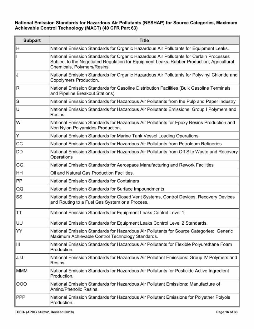
National Emission Standards for Hazardous Air Pollutants (NESHAP) for Source Categories, Maximum Achievable Control Technology (MACT) (40 CFR Part 63)
Subpart Title
H National Emission Standards for Organic Hazardous Air Pollutants for Equipment Leaks.
I National Emission Standards for Organic Hazardous Air Pollutants for Certain Processes Subject to the Negotiated Regulation for Equipment Leaks. Rubber Production, Agricultural Chemicals, Polymers/Resins.
J National Emission Standards for Organic Hazardous Air Pollutants for Polyvinyl Chloride and Copolymers Production.
R National Emission Standards for Gasoline Distribution Facilities (Bulk Gasoline Terminals and Pipeline Breakout Stations).
S National Emission Standards for Hazardous Air Pollutants from the Pulp and Paper Industry
U National Emission Standards for Hazardous Air Pollutants Emissions: Group I Polymers and Resins.
W National Emission Standards for Hazardous Air Pollutants for Epoxy Resins Production and Non Nylon Polyamides Production.
Y National Emission Standards for Marine Tank Vessel Loading Operations.
CC National Emission Standards for Hazardous Air Pollutants from Petroleum Refineries.
DD National Emission Standards for Hazardous Air Pollutants from Off Site Waste and Recovery Operations
GG National Emission Standards for Aerospace Manufacturing and Rework Facilities
HH Oil and Natural Gas Production Facilities.
PP National Emission Standards for Containers
QQ National Emission Standards for Surface Impoundments
SS National Emission Standards for Closed Vent Systems, Control Devices, Recovery Devices and Routing to a Fuel Gas System or a Process.
TT National Emission Standards for Equipment Leaks Control Level 1.
UU National Emission Standards for Equipment Leaks Control Level 2 Standards.
YY National Emission Standards for Hazardous Air Pollutants for Source Categories: Generic Maximum Achievable Control Technology Standards.
III National Emission Standards for Hazardous Air Pollutants for Flexible Polyurethane Foam Production.
JJJ National Emission Standards for Hazardous Air Pollutant Emissions: Group IV Polymers and Resins.
MMM National Emission Standards for Hazardous Air Pollutants for Pesticide Active Ingredient Production.
OOO National Emission Standards for Hazardous Air Pollutant Emissions: Manufacture of Amino/Phenolic Resins.
PPP National Emission Standards for Hazardous Air Pollutant Emissions for Polyether Polyols Production.
TCEQ-(APDG 6422v2, Revised 06/18) Page 17 of 33
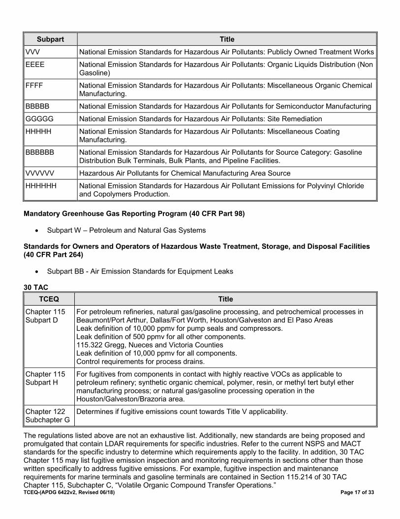
Subpart Title
VVV National Emission Standards for Hazardous Air Pollutants: Publicly Owned Treatment Works
EEEE National Emission Standards for Hazardous Air Pollutants: Organic Liquids Distribution (Non Gasoline)
FFFF National Emission Standards for Hazardous Air Pollutants: Miscellaneous Organic Chemical Manufacturing.
BBBBB National Emission Standards for Hazardous Air Pollutants for Semiconductor Manufacturing
GGGGG National Emission Standards for Hazardous Air Pollutants: Site Remediation
HHHHH National Emission Standards for Hazardous Air Pollutants: Miscellaneous Coating Manufacturing.
BBBBBB National Emission Standards for Hazardous Air Pollutants for Source Category: Gasoline Distribution Bulk Terminals, Bulk Plants, and Pipeline Facilities.
VVVVVV Hazardous Air Pollutants for Chemical Manufacturing Area Source
HHHHHH National Emission Standards for Hazardous Air Pollutant Emissions for Polyvinyl Chloride and Copolymers Production.
Mandatory Greenhouse Gas Reporting Program (40 CFR Part 98)
• Subpart W – Petroleum and Natural Gas Systems
Standards for Owners and Operators of Hazardous Waste Treatment, Storage, and Disposal Facilities (40 CFR Part 264)
• Subpart BB - Air Emission Standards for Equipment Leaks
30 TAC TCEQ Title
Chapter 115 Subpart D
For petroleum refineries, natural gas/gasoline processing, and petrochemical processes in Beaumont/Port Arthur, Dallas/Fort Worth, Houston/Galveston and El Paso Areas Leak definition of 10,000 ppmv for pump seals and compressors. Leak definition of 500 ppmv for all other components. 115.322 Gregg, Nueces and Victoria Counties Leak definition of 10,000 ppmv for all components. Control requirements for process drains.
Chapter 115 Subpart H
For fugitives from components in contact with highly reactive VOCs as applicable to petroleum refinery; synthetic organic chemical, polymer, resin, or methyl tert butyl ether manufacturing process; or natural gas/gasoline processing operation in the Houston/Galveston/Brazoria area.
Chapter 122 Subchapter G
Determines if fugitive emissions count towards Title V applicability.
The regulations listed above are not an exhaustive list. Additionally, new standards are being proposed and promulgated that contain LDAR requirements for specific industries. Refer to the current NSPS and MACT standards for the specific industry to determine which requirements apply to the facility. In addition, 30 TAC Chapter 115 may list fugitive emission inspection and monitoring requirements in sections other than those written specifically to address fugitive emissions. For example, fugitive inspection and maintenance requirements for marine terminals and gasoline terminals are contained in Section 115.214 of 30 TAC Chapter 115, Subchapter C, “Volatile Organic Compound Transfer Operations.”

TCEQ-(APDG 6422v2, Revised 06/18) Page 18 of 33
Appendix A: Tables
Table I: Uncontrolled SOCMI Fugitive Emission Factors Equipment/Service SOCMI Average1 SOCMI Without
Ethylene (C2)2 SOCMI With Ethylene (C2)2
SOCMI Non-Leaker3
Valves
Gas/Vapor 0.0132 0.0089 0.0258 0.00029
Light Liquid 0.0089 0.0035 0.0459 0.00036
Heavy Liquid 0.0005 0.0007 0.0005 0.0005
Pumps
Light Liquid 0.0439 0.0386 0.144 0.0041
Heavy Liquid 0.019 0.0161 0.0046 0.0046
Flanges/Connectors
Gas/Vapor 0.0039 0.0029 0.0053 0.00018
Light Liquid 0.0005 0.0005 0.0052 0.00018
Heavy Liquid 0.00007 0.00007 0.00007 0.00018
Compressors 0.5027 0.5027 0.5027 0.1971
Relief Valve (Gas/Vapor) 0.2293 0.2293 0.2293 0.0986
Open-ended Lines4 0.0038 0.004 0.0075 0.0033
Sampling Connection5 0.033 0.033 0.033 0.0336
Agitators No factors developed; use industry appropriate light liquid pump factors.
Liquid Relief Valves No factors developed; use industry appropriate light liquid valve factors for existing units. New units are expected to have no emissions if they meet BACT.
Endnotes Table I 1 Factors are taken from EPA document, EPA-453/R-95-017, November 1995, Page 2-12. 2 Factors are TCEQ derived, “without Ethylene (C2)” means components contain less than 11% C2 and “with
Ethylene (C2)” means components contain greater than 85%C2 3 Applicable only for components with vapor pressures between 0.0147 psia and 0.147 psia. Control credit is
included in factor; no additional control credit can be applied to these factors. 28PI LDAR program is required.
4 The 28 series quarterly LDAR programs require open-ended lines to be equipped with a cap, blind flange, plug, or a second valve. If so equipped, open-ended lines may be given 100% control credit.
5 Emission factor is in terms of pounds per hour per sample taken. Valves, connectors and open-ended lines should be quantified separately.
6 No factors were developed. The SOCMI sampling connection factor is also used for Non-Leaker.

TCEQ-(APDG 6422v2, Revised 06/18) Page 19 of 33
Table II: Facility/Compound Specific Fugitive Emission Factors Equipment/Service Compound Specific See Section I for more
information Facility Specific1
Ethylene Oxide2 w/LDAR
Phosgene3 w/LDAR
Butadiene w/LDAR4 Petroleum Marketing Terminal5, 6 w/28PET
Oil and Gas ProductionOperation6 Refinery6
Gas Heavy Oil < 20 API
Light Oil Water/ Light Oil
Valves 0.00992 0.0000185 0.0055 0.000216
Gas/Vapor 0.000444 0.00000216 0.001105 0.0000287 0.059
Light Liquid 0.00055 0.00000199 0.00314 0.0000948 0.024
Heavy Liquid 0.0000948 0.00051
Pumps 0.042651 0.0000201 0.05634 0.00529 0.001137 0.02866 0.000052
Light Liquid 0.00119 0.251
Heavy Liquid 0.00119 0.046
Flanges/Connectors11 0.000555 0.00000011 0.000307 0.00086 0.00000086 0.000243 0.000006 0.00055
0.00044 0.0000165 0.000463 0.000243
Gas/Vapor 0.000092604
Light Liquid 0.00001762
Heavy Liquid 0.0000176
Compressors 0.000767 0.000004 0.0194 0.0000683 0.0165 0.0309 1.399
Relief Valve 0.000165 0.0000162 0.02996 0.0194 0.0000683 0.0165 0.0309 0.35
Open-ended Lines8 0.001078 0.00000007 0.00012 0.00441 0.000309 0.00309 0.00055 0.0051
Sampling9 0.000088 0.00012 0.033
Other10 0.0194 0.0000683 0.0165 0.0309
Gas/Vapor 0.000265
Light/Heavy Liquid 0.000287
Process Drains 0.0194 0.0000683 0.0165 0.0309 0.07
Endnotes Table II 1 Factors give the total organic compound emission rate. Multiply by the weight percent of non-methane,
non-ethane organics to get the VOC emission rate. 2 These emission factors require the use of the 28MID fugitive program. Monitoring must occur at a leak
definition of 500 ppmv. No additional control credit can be applied to these factors except 28CNTQ and 28CNTA. Emission factors are from EOIC Fugitive Emission Study, summer 1988.
3 These emission factors require the use of the 28MID fugitive program. Monitoring must occur at a leak definition of 50 ppmv. No additional control credit can be applied to these factors. Emission factors are from Phosgene Panel Study, summer 1988.
4 These emission factors require the use of the 28MID fugitive program. Monitoring must occur at a leak definition of 100 ppmv. No additional control credit can be applied to these factors. Emission factors are from Randall, J. L., et al., Radian Corporation. Fugitive Emissions from the 1,3-butadiene Production Industry: A Field Study. Final Report. Prepared for the 1,3-Butadiene Panel for the Chemical Manufacturers Association. April 1989.
5 Control credit is included in the factor; no additional control credit can be applied to these factors. Monthly 28 PET inspection is required.
6 Factors are taken from EPA Document EPA-453/R-95-017, November 1995, pages 2-13, 2-14, and 2-15. 7 Heavy liquid oil – Pump factor was not derived during the API study. The factor is the SOCMI without C2
Heavy Liquid – Pump factor with a 93% reduction credit for the physical inspection.
TCEQ-(APDG 6422v2, Revised 06/18) Page 20 of 33
8 The 28 Series quarterly LDAR programs require open-ended lines to be equipped with a cap, blind flange, plug, or a second valve. If so equipped, open-ended lines may be given a 100% control credit.
9 Emission factor for sampling connections is in terms of pounds per hour per sample taken. 10 For Petroleum Marketing Terminals, “Other” includes any component excluding fittings, pumps, and valves.
For Oil and Gas Production Operations, “Other” includes diaphragms, dump arms, hatches, instruments, meters, polished rods, and vents.
11 For Oil and Gas Production Operations, separate factors are given for “Flanges” and “Connectors.” The factor for “flanges” is shown on the top line, and the factor for “connectors” is on the line below

TCEQ-(APDG 6422v2, Revised 06/18) Page 21 of 33
Table III: Leak Detection and Repair (LDAR) Program Instrument Monitoring Options
LDAR Program 28M 28RCT 28VHP 28MID 28LAER 28CNTQ 28CNTA
Leak Definition for Pumps and Compressors
10,000 ppmv 10,000 ppmv 2,000 ppmv 500 ppmv 500 ppmv N/A N/A
Leak Definition for All Other Components
10,000 ppmv 500 ppmv 500 ppmv 500 ppmv 500 ppmv 500 ppmv 500 ppmv
Applicable Vapor Pressure
>0.5 psia at100°F
>0.044 psia at68°F
>0.044 psia at68°F
>0.044 psia at68°F
>0.044 psia at68°F
>0.044 psia at68°F
>0.044 psia at68°F
Monitoring Frequency
Quarterly Quarterly Quarterly Quarterly Quarterly Quarterly Annually
Directed/Nondirected Maintenance
Nondirected Nondirected Nondirected Directed Directed Nondirected Nondirected
Most Common State/Federal Programs with Similar Requirements
40 CFR Part 60 Subpart VV 40 CFR Part 61 30 TAC §115.322
30 TAC §115.3521
40 CFR Part 60 Subpart VVa 40 CFR Part 63 Subparts H, CC
N/A Nonattainment NSR
N/A 40 CFR Part 60Subpart VVa, 40 CFR Part 63 Subparts H, CC
Endnotes Table III 1 Except in Gregg, Nueces, and Victoria Counties where 28M applies.

TCEQ-(APDG 6422v2, Revised 06/18) Page 22 of 33
Table IV: LDAR Program Physical Inspection Options
LDAR Program 28AVO1 28PET2 28PI3
Monitoring Frequency Every 4 hours Monthly Weekly
Repair Schedule Immediately, but no later than one hour after leak is found
As soon as practicable but no later than 15 days after leak is found
As soon as practicable but no later than 15 days after leak is found
Directed/Nondirected Maintenance
N/A N/A N/A
Endnotes Table IV 1 28AVO is an audio, visual and olfactory leak detection and repair program allowed only for specific
compounds. TCEQ Management approval is required to use this program for compounds other than chlorine, ammonia, hydrogen sulfide, hydrogen fluoride, mercaptans, and hydrogen cyanide.
2 28PET is a petroleum marketing terminal audio, visual and olfactory leak detection and repair program. 28PET is an AVO LDAR program that is only available for petroleum marketing terminals as approved by TCEQ
3 28PI is a physical inspection audio, visual and olfactory leak detection and repair program.

TCEQ-(APDG 6422v2, Revised 06/18) Page 23 of 33
Table V: Control Efficiencies for LDAR
Equipment/Service 28M 28RCT 28VHP 28MID 28LAER 28CNTQ 28CNTA 28PI 28AVO9
Valves1 97%
Gas/Vapor 75% 97% 97% 97% 97% 30%
Light Liquid 75% 97% 97% 97% 97% 30%
Heavy Liquid5 0%6 0%6 0%6 0%6 30%6, 8 30%8
Pumps1 93%
Light Liquid 75% 75% 85% 93% 93% 30%
Heavy Liquid5 0% 0%7 0%7 0%8, 10 30%8 30%8
Flanges/Connectors1 30% 30% 30% 30% 30% 97%
Gas/Vapor 97% 97% 75%
Light Liquid 97% 97% 75%
Heavy Liquid8 30% 30% 30%
Compressors1 75% 75% 85% 95% 95% 30% 95%
Relief Valves1, 2 (Gas/Vapor)
75% 97% 97% 97% 97% 30% 97%
Sampling Connection3 (pounds per hour per sample taken)
0% 0% 0% 0% 0% 0% 0%
Open Ended Lines1, 4
It should be noted in the application and added to the permit conditions if any of the footnotes are applicable. For example, if components in heavy liquid service are monitored, then the application should include the monitored concentration and the concentration of saturation, in ppmv and such monitoring will be added as a separate condition.
Endnotes Table V 1 Control efficiencies apply only to components that are actually monitored. Control efficiencies do not apply
to components that are difficult or unsafe-to-monitor on the standard schedule. However, difficult-to-monitor gas or light liquid valves under the 28RCT, 28VHP, 28MID, or 28LAER programs that are monitored once per year may apply a 75% reduction credit.
2 100% control may be taken if a relief valve vents to an operating control device or if it is equipped with a rupture disc and a pressure-sensing device between the valve and disc to monitor for disc integrity. For new facilities, BACT guidelines generally require that all relief valves vent to a control device. When there are safety reasons that the relief valve cannot achieve 100% control, the relief valve can be monitored under the LDAR programs for the credit listed. This monitoring must be performed regardless of whether the relief valve is considered accessible, difficult-to-monitor or unsafe-to-monitor. Relief valves that do not achieve 100% control should not be built in locations that are unsafe-to-monitor.
3 Sampling connection control efficiencies are covered under other equipment and services. Sampling emissions are based on the number of samples taken per year as opposed to the number of connections. Fugitives for a closed loop sampling system are based on the component count.
4 Good design criteria for special chemicals handling and most LDAR programs require open-ended lines to be equipped with an appropriately sized cap, blind flange, plug, or a second valve. If so equipped, open-ended lines may be given a 100% control credit. Regardless of the lines given 100% credit, these lines should be mentioned in permit applications. Exceptions to the LDAR program criteria may be made for safety reasons with the approval of TCEQ management.

TCEQ-(APDG 6422v2, Revised 06/18) Page 24 of 33
5 Monitoring components in heavy liquid service using an instrument is not required by any of the 28 Series LDAR programs. If monitored with an instrument, the applicant must demonstrate that the VOC being monitored has sufficient vapor pressure to allow for reduction credit. Monitoring near or below background concentration is unreasonable and additional credit is not given for monitoring generic VOC below 500 ppmv. Credit will be given in cases where a specific compound is monitored below 500 ppmv when sufficient demonstration has been made of the ability to monitor at the specified concentration and there is no concern about the monitoring concentration being close to the background concentration. No credit may be taken if the concentration at saturation is below the leak definition of the monitoring program (i.e. (0.044 psia/14.7 psia) x 106 = 2,993 ppmv versus leak definition = 10,000 ppmv).
6 If the concentration at saturation is greater than the leak definition. Contact the TCEQ to determine whether valves in heavy liquid service may be given a 97% credit if monitored at 500 ppmv
7 If the concentration at saturation is greater than the leak definition. Contact the TCEQ to determine whether pumps in heavy liquid service may be given a 85% reduction credit if monitored at 2,000 ppmv.
8 Ultra heavy liquid with a vapor pressure < 0.0147 psia at operating temperature may receive higher emission reduction credit (matching the credit of 28AVO) provided a 28PI inspection program is performed on these components.
9 Audio, Visual and Olfactory (AVO) – AVO credit is based on the chemical constituent, not vapor pressure or service type. This program (28AVO) is approved for chlorine, ammonia, hydrogen sulfide, hydrogen fluoride, mercaptans, and hydrogen cyanide only.
10 If the concentration at saturation is greater than the leak definition. Contact the TCEQ to determine whether pumps in heavy liquid service may be given a 93% credit if monitored at 500 ppmv.

TCEQ-(APDG 6422v2, Revised 06/18) Page 25 of 33
Table VI: Sample Fugitive Emission Rate Calculations for a Chemical Plant Implementing the 28VHP LDAR Program
Component Name Stream Type Number of Components SOCMI w/o C2, Emission Factors
Valves Gas/Vapor 1,019 0.0089
Valves Light Liquid 2,263 0.0035
Pumps Light Liquid 14 0.0386
Connectors Gas/Vapor 1,435 0.0029
Connectors Light Liquid 3,056 0.0005
Compressors Gas/Vapor 1 0.5027
Relief Valves Gas/Vapor 12 0.2293
Open-Ended Gas/Vapor 3 0.0040
Component Name LDAR Program Control Efficiency Controlled Emission rate
lbs/hr
Controlled Emission Rate
Tons/Year
Valves 28VHP 97% 0.27 1.19
Valves 97% 0.24 1.04
Pumps 85% 0.08 0.36
Connectors 97%1 0.12 0.55
Connectors 97%2 0.05 0.20
Compressors 85% 0.08 0.33
Relief Valves 100%3 0.00 0.00
Open-Ended 100%4 0.00 0.00
Total Fugitive Emission Rates 0.84 3.67
Endnotes Table VI 1 Connectors monitored at 500 ppmv; therefore, the 28 CNTQ control credit is applied. 2 Connectors monitored at 500 ppmv; therefore, the 28 CNTQ control credit is applied. 3 Relief valves routed to a flare; therefore, 100% control credit is applied. 4 The 28 Series LDAR Programs require open-ended lines to be equipped with a cap, blind flange, plug, or a
second valve for 100% control credit. The connector count is increased by the number of open-ended lines to account for the credit.
TCEQ-(APDG 6422v2, Revised 06/18) Page 26 of 33
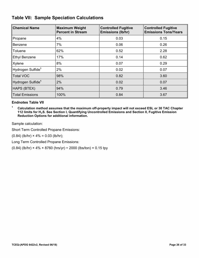
Table VII: Sample Speciation Calculations
Chemical Name Maximum Weight Percent in Stream
Controlled Fugitive Emissions (lb/hr)
Controlled Fugitive Emissions Tons/Years
Propane 4% 0.03 0.15
Benzene 7% 0.06 0.26
Toluene 62% 0.52 2.28
Ethyl Benzene 17% 0.14 0.62
Xylene 8% 0.07 0.29
Hydrogen Sulfide1 2% 0.02 0.07
Total VOC 98% 0.82 3.60
Hydrogen Sulfide1 2% 0.02 0.07
HAPS (BTEX) 94% 0.79 3.46
Total Emissions 100% 0.84 3.67
Endnotes Table VII 1 Calculation method assumes that the maximum off-property impact will not exceed ESL or 30 TAC Chapter
112 limits for H2S. See Section I, Quantifying Uncontrolled Emissions and Section II, Fugitive Emission Reduction Options for additional information.
Sample calculation:
Short Term Controlled Propane Emissions:
(0.84) (lb/hr) × 4% = 0.03 (lb/hr);
Long Term Controlled Propane Emissions:
(0.84) (lb/hr) × 4% × 8760 (hrs/yr) ÷ 2000 (lbs/ton) = 0.15 tpy
TCEQ-(APDG 6422v2, Revised 06/18) Page 27 of 33
Appendix B
Section I: History of Calculation Methods for Equipment Leak Fugitives
A fugitive emission is defined in 30 TAC Chapter 115 as “any volatile organic compound entering the atmosphere that could not reasonably pass through a stack, chimney, vent, or other functionally equivalent opening designed to direct or control its flow”. Examples include dust from aggregate piles, leaks around gaskets and fittings on transport vessels, and leaks from piping fittings. The most common usage of the term “fugitives” or “fugitive emissions” in the petrochemical and refining industry refers to the emissions from leaking piping components including valves, connectors, pump seals, compressor seals and relief valves.
The state of Texas began requiring permitting of construction and operation of air emission sources in 1971. The EPA began regulating the permitting of major sources in 1978. However, early permitting focused on control of point sources and it was not until 1986 that the agency began to consistently include calculation of emissions of piping fugitives in the permit review and on the maximum allowable emission rate table. Prior to this time, it was difficult to quantify fugitive emissions since limited studies on the emissions from piping components had been done.
The earliest study on piping fugitives was a California study done in 1957-58. This study provided factors for calculating fugitive emissions which were reported in the earliest version of AP-42 “Compilation of Air Pollution Emission Factors.” The next significant study was the EPA/Radian study which generated an EPA guidance document in February 1979 and generated the factors used for refinery fugitive emissions. Additional studies at petrochemical facilities generated the SOCMI factors which appeared in an EPA guidance document dated April 1982. These factors were revised in the mid-1990’s to the SOCMI factors currently in use today.
These studies were based on “bagging” a piping component and measuring the mass of material which leaked from the component over a set period of time. Bagging a component means the component was completely enclosed in a gas impermeable material such as Mylar or Teflon. Strict protocols were followed during the testing and a statistically significant number of components for each component and service type had to be sampled from a number of facilities in order to generate sufficient information to develop relevant leak rate factors. Factors were developed for specific component type and service within a specific study. For example, the original refinery study developed factors for piping components at refineries which included valves, connectors, pumps, compressors, relief valves and other. Within the individual component type, the factors were further broken down by service type (gas/vapor, light liquid and heavy liquid). Over the years fugitive factors have been developed and approved for a number of different industries and three specific compounds. The studies were conducted by various industry or trade organizations using EPA protocols and the final results were reviewed and approved by EPA. For a number of these studies, information was also supplied to the agency in conjunction with the EPA regarding the studies.
The development of specific LDAR monitoring programs is described below.
28 Series Nomenclature - Please be aware that the naming system used for the 28 series LDAR programs are not generally acronyms and reflects the use of changing technology at the agency. The “28” originated with the storage of standardized conditions on magnetic tape drives to speed typing of permits. The fugitive LDAR program 28M was stored on magnetic tape drive number 28 hence the reference name for permit reviewers. As more LDAR programs were developed the use of the 28 designation continued to identify the condition as an LDAR program. The letters added to the “28” were the developer’s shorthand for the focus of the LDAR program. For example, 28RCT was developed when changes were made to the LDAR programs found in 30 TAC Chapter 115. The 28 identifies the condition as an LDAR program while the RCT was shorthand for the RACT (reasonably available control technology) generally required by the state regulation. Another example would be 28CNTA where the CNT is shorthand for connector and the A indicates annual monitoring. The 28LAER program is the only one that is truly an acronym and should be updated to reflect LAER for piping fugitives. Some of these LDAR programs are not acronyms and the names reflect magnetic tape drive storage locations or shorthand for the developer’s use.

TCEQ- (APDG 6422v2, Revised 06/18) Page 28 of 33
28M – 1st leak detection and repair program developed that required monitoring using Method 21. The requirements of this program are compatible with NSPS Subpart VV and the program was originally BACT for piping fugitives. The program was developed around 1986.
28MD – This program was developed in the late 1980’s and is no longer in use. The program was a monthly monitoring program with a 10,000 ppm leak definition. The program was used for ethylene and propylene. The program was retired in 1995 when it was determined it was more appropriate to give credit for reducing the leak definition rather than increasing the monitoring frequency.
28MID – This program was developed in the later 1980’s and is compound specific. It was developed to address off property impact problems associated with piping fugitive emissions from a specific compound. The condition allows an applicant to select the percentage of the compound in question at which the program applies. The program is the most stringent voluntary program and requires directed maintenance.
28AVO – This program was developed in the late 1980’s to address specific chemicals with a high odor nuisance or other potential that cannot be monitored. These compounds include ammonia, chlorine, hydrogen sulfide, hydrogen fluoride and mercaptans.
28VHP – Development of this program began in 1993 as more applicants began voluntarily implementing 28MID for general VOC fugitives in order to reduce emissions for federal applicability purposes. A new level of Tier 1 BACT for piping fugitives was demonstrated and a new LDAR program proposed. The program originally proposed a leak definition of 500 ppm for all components; however, this was increased to 1,000 ppm for pumps and compressors due to industry concerns with the ability of older existing pump and compressor seals to meet 500 ppm. The HON MACT (40 CFR Part 63 Subpart H) was proposed during the finalization of the 28VHP requirements resulting in a decision to raise the leak definition for pumps and compressors to 2,000 ppm to avoid potential conflict between BACT and the MACT standard. The program became BACT for facilities with uncontrolled fugitive emission ≥25 TPY in 1995.
28RCT – This program was developed in 1995 in response to changes to Chapter 115 for VOC fugitives.
28LAER – This LDAR program was developed for fugitive emissions subject to nonattainment new source review permitting. It combines the most stringent aspects of all the available LDAR programs and was developed in the mid-990’s.
28CNTA– This program was developed in 1995 in direct response to the connector monitoring requirement in the HON MACT. Applicants asked for a reduction credit for the connector monitoring required by the HON. A reduction credit of 75% was determined to be appropriate. The LDAR program was developed to allow other facilities to use the credit.
28CNTQ – This program was developed after 28CNTA in response to requests for additional monitoring credits to generate reductions in nonattainment areas.
28PET– The Petroleum Marketing Terminal Factors were developed in the early 1990’s. The factors were reviewed by the agency and the EPA and were included in the EPA document “Protocol for Equipment Leak Emission Estimates, “EPA document EPA-453/R-95-017, available at the EPA’s Web site at www3.epa.gov/ttnchie1/efdocs/equiplks.pdf. The decision to require a physical LDAR program instead of an instrument monitoring program was based on the EPA/API bagging study which included gasoline distribution facilities employing a variety of inspection and maintenance programs ranging from simple physical inspections to organic vapor analyzer (OVA) instrument monitoring. The results of the study indicated little or no improvement in fugitive emission control was associated with inspection programs utilizing instrument monitoring to detect leaks. This finding was confirmed during conversations with both EPA and API representatives. See Interoffice Memorandum dated 3/27/1996, www.tceq.texas.gov/assets/public/permitting/air/memos/historical_memos/histmemo3-1996.pdf
28PI – The use of a weekly physical inspection for components in heavy liquid service was allowed for several years without a formal LDAR program being developed. In the early 2000’s a physical inspection LDAR condition was formally developed in order to improve consistency. The program contains a weekly physical inspection requirement and the boilerplate “28 series” language which deals with the non-inspection requirements such as construction standards and repair.

TCEQ-(APDG 6422v2, Revised 06/18) Page 29 of 33
Section II Discussion of Method 21, for more information please refer to www.epa.gov/emc/method-21-volatile-organic-compound-leaks
The instrument monitoring of piping components is performed using Method 21, found in 40 CFR Part 60, Appendix A. This test method includes performance specifications for the monitor to be used, calibration requirements, and guidelines for how each component should be tested. The most common types of monitors used in conjunction with Method 21 are flame ionization detectors (FIDs) and photoionization detectors (PIDs). Both are acceptable and which type is selected is generally dependent on the compounds being monitored since the detector must respond to the compounds being processed and must be capable of measuring the specified leak definition.
The first step in the Method 21 procedure is the evaluation of performance for the instrument selected against the performance criteria of Method 21. For each VOC to be measured, the response factor must be <10 unless otherwise specified in a specific regulation. The response factor is the ratio of the known concentration of a VOC compound to the observed meter reading of an instrument calibrated with the specified reference compound. The calibration precision must be <10% of the calibration gas value. The calibration precision is the relative percentage of the average difference between the meter readings and the known concentration. The response time of the instrument must be less than or equal to 30 seconds. This is the time interval from a step change in VOC concentration at the input of the sampling system to the time at which 90% of the corresponding final value is reached as displayed on the instrument readout meter. The evaluation of the monitoring instrument is usually performed once when the monitor is selected, although, additional evaluation must be performed if new compounds are added to the process streams subject to monitoring.
The second step in the Method 21 procedure is instrument calibration. The instrument must be calibrated before each monitoring episode or daily. At least two calibration gases must be used for instrument calibration and performance evaluation. A zero gas standard (air with less than 10 ppmv VOC) and a known reference gas at a concentration approximately equal to the applicable leak definition are used to calibrate the instrument. The reference gas may be specified by a specific regulation or may be selected based upon the response factors of the compounds being monitored.
The third step in the Method 21 procedure specifies how the monitoring is to be performed for each component type. The monitor probe must be placed at the surface of the component interface where leakage could occur. The probe is then moved along the interface periphery while observing the instrument readout. The monitor readout is observed while the probe is moved to locate the maximum reading. The probe is kept at the location of the maximum reading for 2 times the response time to ensure a stable reading is recorded. If the concentration reading is above the applicable leak definition, then the component is leaking and must be repaired. All maximum readings, leakers and non-leakers, are recorded.
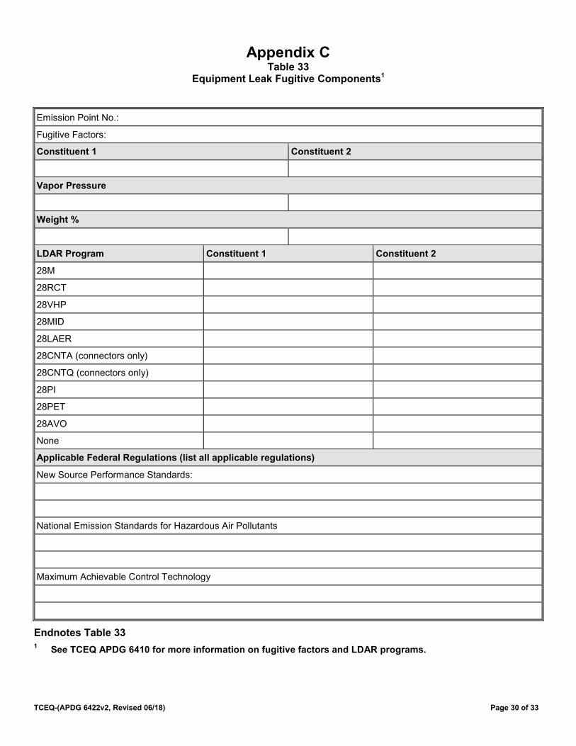
TCEQ-(APDG 6422v2, Revised 06/18) Page 30 of 33
Appendix C Table 33
Equipment Leak Fugitive Components1
Emission Point No.:
Fugitive Factors:
Constituent 1 Constituent 2
Vapor Pressure
Weight %
LDAR Program Constituent 1 Constituent 2
28M
28RCT
28VHP
28MID
28LAER
28CNTA (connectors only)
28CNTQ (connectors only)
28PI
28PET
28AVO
None
Applicable Federal Regulations (list all applicable regulations)
New Source Performance Standards:
National Emission Standards for Hazardous Air Pollutants
Maximum Achievable Control Technology
Endnotes Table 33 1 See TCEQ APDG 6410 for more information on fugitive factors and LDAR programs.

TCEQ-(APDG 6422v2, Revised 06/18) Page 31 of 33
Table 33 Equipment Leak Fugitive Components
Service Component Constituent 1 Total Quality
Constituent 1 Difficult-to-Monitor
Constituent 2 Total Quantity
Constituent 2 Difficult-to-Monitor
Gas/Vapor Valves
Flanges and Connectors
Compression Fittings
Other
Compressor
Heavy Liquid Valves
Flanges and Connectors
Compression Fittings
Other
Pumps
Light Liquid Valves
Flanges and Connectors
Compression Fittings
Other
Pumps
Water/Oil Valves
Flanges and Connectors
Compression Fittings
Other
Pumps
All Open-ended Lines2
Sampling Connections3
Endnotes Table 33 2 The 28 Series quarterly LDAR programs require open-ended lines to be equipped with a cap, blind flange,
plug, or a second valve. If so equipped, open-ended lines may be given a 100% control credit. 3 Emission factor for Sampling Connections is in terms of pounds per hour per sample taken.
Appendix D
Acronyms For a complete list of acronyms and abbreviations that are commonly used by TCEQ in air permitting, please refer to the Air Permitting Acronyms and Other Abbreviations list on the APD website.
FEF: Fugitive Emission Factor. TAC: Texas Administrative Code.
CFR: Code of Federal Regulations
Definitions Be aware that there are often differences in term usage and term definitions between the state and federal regulatory agencies.
Best Available Control Technology or BACT: an air pollution control method for a new or modified facility that through experience and research, has proven to be operational, obtainable, and capable of reducing or eliminating emissions from the facility, and is considered technically practical and economically reasonable for the facility. The emissions reduction can be achieved through technology such as the use of add-on control equipment or by enforceable changes in production processes, systems, methods, or work practice. Reference: 30 TAC § 116.10.
Chemical Species: individual air contaminant with a specific effects screening level (ESL)
Constituent: an essential part or component of a chemical mixture or of an emissions stream; for instance, benzene is one constituent of gasoline.
Dead crude and or weathered crude: Crude oil that has already been depressurized such that atmospheric entrained volatile constituents have been removed (flashed off).
Difficult-to-monitor: A component that qualifies for reduced monitoring frequency because it cannot be inspected without elevating the monitoring personnel more than two meters above a permanent support surface or that requires a permit for confined space entry as defined in 29 CFR §1910.146 (December 1, 1998). Also, see the definition “Non-accessible.” Reference: 30 TAC Chapter 115 and Chapter 29; CFR §1910.146.
Dripping liquid: Generally refers to leaking process fluids not including lubricants such as lube oil.
Effects Screening Level or ESL: guideline concentrations derived by the Texas Commission on Environmental Quality (TCEQ) and used to evaluate ambient air concentrations of constituents. ESLs are based on a constituent’s potential to cause adverse health effects, odor nuisances, vegetation effects, or materials damage. Health-based screening levels are set at levels lower than those reported to produce adverse health effects, and are set to protect the general public, including sensitive subgroups such as children, the elderly, or people with existing respiratory conditions. If an air concentration of a constituent is below the screening level, adverse effects are not expected. If an air concentration of a constituent is above the screening level, it is not indicative that an adverse effect will occur, but rather that further evaluation is warranted.
Emission Point: point where constituent emissions are released into the air. Emission Point Number or EPN: unique identification number assigned to an emission point.
Emission Unit: any part of a stationary source that emits or would have the potential to emit any regulated NSR pollutant or any pollutant listed under FCAA § 112(b). Reference: 40 CFR § 51.166(b)(7). Note: TCEQ equates the federal term “emission unit” with the state term “facility.” The state term is at least as stringent as the federal term. Reference: THSC § 382.003(6).
Facility: a discrete or identifiable structure, device, item, equipment, or enclosure that constitutes or contains a stationary source, including appurtenances other than emission control equipment. A mine, quarry, well test or
TCEQ-(APDG 6422v2, Revised 06/18) Page 32 of 33

TCEQ-(APDG 6422v2, Revised 06/18) Page 33 of 33
road is not considered to be a facility. For the purpose of emissions inventory, this term does not refer to the entire site but to individual process units at the site.
Heavy liquid: A liquid with vapor pressure less than 0.0440 psia at 68°F. Light liquid: A liquid with vapor pressure greater than or equal to 0.0440 psia at 68°F.
Non-accessible: Terminology once used to describe components that qualified for reduced monitoring frequency because they could not be monitored without elevating monitoring personnel above a permanent support structure. The term “difficult-to-monitor” is now used instead for consistency with 30 TAC Chapter 115. psi: pounds per square inch. A unit of pressure. psia: pounds per square inch absolute. This is a unit for pressure measured relative to a full vacuum. Chemicals with higher psia values for their measured vapor pressure evaporate faster. psig: pounds per square inch gauge. This is a unit for pressure measured relative to ambient atmospheric pressure. This is the value measured when a gauge is used to measure a pressure vessel. This is the difference in pressure between the atmosphere and the item measured. At sea level, the conversion between psia and psig is psig+14.7= psia
Ultra-Heavy Liquid: A liquid with vapor pressure less than 0.0147 psia at 68°F.
Unsafe-to-monitor: A component that the owner or operator determines is unsafe-to-monitor because monitoring personnel would be exposed to an immediate danger as a consequence of conducting the monitoring.