air preparation products - lydey automationair purity class - iso 8573-1:2010 5µ (5:8:4) 25µ...
TRANSCRIPT

651 Series | 652 Series | 653 SeriesFilter Regulator Lubricator (FRL)
Air Preparation Products
SERIES
651/652/653 ASCO NUMATICS™
Air Purity Class - ISO 8573-1:20105µ (5:8:4)25µ (6:8:4)40µ (7:8:4)
Materials in Contact with FluidBody AluminumSeals NBR/FKMFilter Element Sintered PolyethyleneBowl Polycarbonate or Aluminum
Performance DataSeries 651 652 653Port Sizes 1/8, 1/4 1/4, 3/8, 1/2 1/2, 3/4, 1Thread Type NPTF, G & Rc
Nominal Flow - Per ISO 6358
P1 = 91.4 PSI (6.3 bar)ΔP = 14.5 PSI (1 bar)
Micron Rating SCFM (L/min ANR)
1/85µ 31.2 (885) - -25µ 32.5 (920) - -40µ 34.6 (980) - -
1/45µ 44.1 (1250) 70.8 (2020) -25µ 49.6 (1410) 89.3 (2250) -40µ 54.7 (1550) 92.4 (2640) -
3/85µ - 76.5 (2190) -25µ - 118.7 (3390) -40µ - 135.5 (3870) -
1/25µ - 80.2 (2290) 136.0 (3850)25µ - 129.5 (3700) 162.4 (4600)40µ - 153.0 (4370) 196.0 (5550)
3/45µ - - 141.3 (4000)25µ - - 166.0 (4700)40µ - - 229.5 (6500)
15µ - - 150.1 (4250)25µ - - 176.6 (5000)40µ - - 245.4 (6950)
Maximum Inlet Pressure PSIG (bar)Polycarbonate Bowl 232 (16) 174 (12)
Aluminum Bowl 232 (16) 290 (20)Ambient Temperature Range °F (°C) -4 to 122 (-20 to 50)Fluid Temperature Range °F (°C) -4 to 122 (-20 to 50)Fluid Air or Inert Gas
Weight Ibs. (kg)w/Polycarbonate Bowl 0.52 (0.238) 0.94 (0.426) 2.06 (0.934)
w/Aluminum Bowl 0.84 (0.382) 1.22 (0.553) 2.51 (1.140)
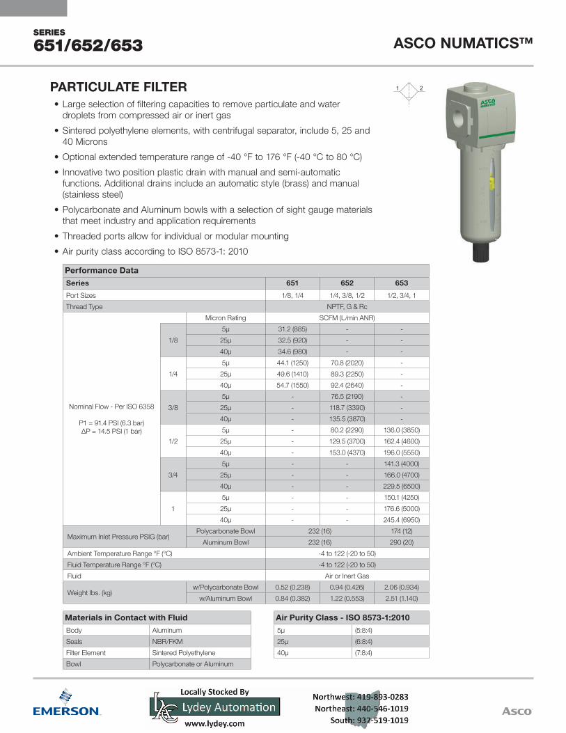
• Large selection of filtering capacities to remove particulate and waterdroplets from compressed air or inert gas
• Sintered polyethylene elements, with centrifugal separator, include 5, 25 and40 Microns
• Optional extended temperature range of -40 °F to 176 °F (-40 °C to 80 °C)• Innovative two position plastic drain with manual and semi-automatic
functions. Additional drains include an automatic style (brass) and manual(stainless steel)
• Polycarbonate and Aluminum bowls with a selection of sight gauge materialsthat meet industry and application requirements
• Threaded ports allow for individual or modular mounting• Air purity class according to ISO 8573-1: 2010
PARTICULATE FILTER

SERIES
651/652/653ASCO NUMATICS™
1
1 Conforms to ISO standards 1179-12 If multiple options are required, please use the online CAD
configurator on the website to generate the part number(www.asco.com), or consult factory
3 Compressed air must be dry enough so no ice formation is present on the product. All bowls should be emptied prior to ambient temperatures dropping below 32 °F (0 °C)
Port Size1 = 1/8 (651 Series)2 = 1/4 (651 or 652 Series)3 = 3/8 (652 Series)4 = 1/2 (652 or 653 Series)5 = 3/4 (653 Series)6 = 1 (653 Series)
101
2
3
OptionsA00 = No Options101 = Side Mounting Brackets105 = High Temperature (80 °C/176 °F)106 = Low Temperature (-40 °C/-40 °F)109 = FKM Seals117 = ATEX Zones 1–21 202 = 105 + 1092A9 = 105 + 106
QNA
Drain Type0 = No DrainA = Auto Drain Normally OpenN = Manual - Semi-automatic DrainQ = Manual Drain - Stainless Steel
PNK/L/M
Bowl TypeK = Metal Bowl without Sight GaugeL = Metal Bowl with Sight Gauge (Glass)M = Metal Bowl with Sight Gauge (Polyamide)N = Polycarbonate Bowl without Bowl Guard (651 only)P = Polycarbonate Bowl with Bowl Guard
JBA
ElementsA = 40 Micron (Green)B = 5 Micron (White)J = 25 Micron (Yellow)
Product TypeB = Filter - Particulate
RevisionA
Product Series651652653
Port Type8 = NPTFG = ISO 228/1-GJ = ISO 7/1 Rc
8 651 A B B P 2 J A00 0 N
How to Order - Particulate Filter
Locally Stocked Coalescing Filters8651ABBP2JA000N 8652ABBP3JA000N 8652ABBP4JA000N 8653ABBP5JA000N 8653ABBP6JA000N

SERIES
651/652/653 ASCO NUMATICS™
Air Purity Class - ISO 8573-1:2010*0.3 µm (3:7:3)0.01 µm (2:7:2)
* 651 Series maximum flow at 91.4 PSI (6.3 bar) inlet pressure to maintain air purity class is 3.5 SCFM (100 L/min)
* 652 Series maximum flow at 91.4 PSI (6.3 bar) inlet pressure to maintain air purity class is 10.6 SCFM (303 L/min)
* 653 Series maximum flow at 91.4 PSI (6.3 bar) inlet pressure to maintain air purity class is 25.0 SCFM (707 L/min)
* 653 Series - High Flow maximum flow at 91.4 PSI (6.3 bar) inlet pressure to maintain air purity class is 58.0 SCFM (1,641 L/min)
Materials in Contact with FluidBody AluminumSeals NBR/FKMCoalescing Filter Element Borosilicate Microfiber & PolyesterFilter Element End Cap PolypropyleneAdsorber Activated CarbonBowl Polycarbonate or Aluminum
Performance DataSeries 651 652 653 653 High Flow
Port Sizes 1/8, 1/4 1/4, 3/8, 1/2 1/2, 3/4, 1 1Thread Type NPTF, G & Rc
Nominal Flow - Per ISO 6358
P1 = 91.4 PSI (6.3 bar)ΔP = 5 PSI (0.35 bar)
Micron Rating SCFM (L/min ANR)
1/80.3 µm 15.3 (430) - - -0.01 µm 10.9 (310) - - -
1/40.3 µm 17.0 (480) 28.0 (800) - -0.01 µm 12.4 (350) 25.0 (710) - -
3/80.3 µm - 28.6 (820) - -0.01 µm - 27.5 (790) - -
1/20.3 µm - 30.5 (870) 81.2 (2300) -0.01 µm - 29.1 (830) 63.6 (1800) -
3/40.3 µm - - 90.0 (2550) -0.01 µm - - 67.1 (1900) -
10.3 µm - - 91.8 (2600) 291.3 (8250)0.01 µm - - 79.5 (2250) 271.9 (7700)
Maximum Inlet Pressure PSIG (bar)Polycarbonate Bowl 232 (16) 174 (12) -
Aluminum Bowl 232 (16) 290 (20)Ambient Temperature Range °F (°C) 35 to 122 (1.7 to 50) Fluid Temperature Range °F (°C) 35 to 122 (1.7 to 50) Fluid Air or Inert Gas
Weight Ibs. (kg)w/Polycarbonate Bowl 0.54 (0.245) 0.98 (0.442) 3.18 (1.442) N/A
w/Aluminum Bowl 0.86 (0.390) 1.25 (0.569) 2.72 (1.234) 4.03 (1.828)
• Extensive range of coalescing filter elements to remove oil andsub-micron particles down to 0.01 microns. Air purity classaccording to ISO 8573-1: 2010
• Optional 3 micron pre-filter integrated in the coalescing elementeliminates the need for a separate particulate element. Coalescingfilter elements include 0.3 and 0.01 microns
• Adsorber filter (activated carbon) for removal of odors and hydrocarbon vapor• 653 High Flow Coalescer optimizes overall 653 manifold flow; use transition
adapters to step up from 651 to 652 or 652 to 653 filters when needed• Polycarbonate and Aluminum bowls with a selection of sight gauge materials
that meet industry and application requirements• Optional extended temperature range of 176 °F (80 °C)• Visual or electrical differential pressure Indicators for condition monitoring
of filter element
COALESCING FILTER & ADSORBER
651/652/653 653 High Flow

SERIES
651/652/653ASCO NUMATICS™
Port Size1 = 1/8 (651 Series)2 = 1/4 (651 or 652 Series)3 = 3/8 (652 Series)4 = 1/2 (652 or 653 Series)5 = 3/4 (653 Series)6 = 1 (653 Series)
HE
Indication TypeE = Electric Differential Pressure Indicator H = Differential Pressure Visual Pop-up
Indicator J = No Differential Pressure Indicator
101
3 OptionsA00 = No Options101 = Side Mounting Brackets105 = High Temperature (80 °C/176 °F)109 = FKM Seals117 = ATEX Zones 1–21 202 = 105 + 109
QNA
Drain Type0 = No DrainA = Auto Drain Normally OpenN = Manual - Semi-automatic DrainQ = Manual Drain - Stainless Steel
PNK/L/MK (High Flow)
Bowl TypeK = Metal Bowl without Sight GaugeL = Metal Bowl with Sight Gauge (Glass)M = Metal Bowl with Sight Gauge (Polyamide)N = Polycarbonate Bowl without Bowl Guard (651 only)P = Polycarbonate Bowl with Bowl Guard
FE/ND/M
ElementsD = 0.3 Micron - Coalescer (Green)E = 0.01 Micron - Coalescer (Red)F = Adsorber - Activated Carbon (Gray)M = 0.3 Micron Coalescer with 3 Micron
Prefilter (Green)N = 0.01 Micron Coalescer with 3 Micron
Prefilter (Red)
HA/F
2
Product TypeA = Adsorber - Activated Carbon (All Series)F = Filter - Coalescing (All Series)H = High Flow Version (653 Series Filter only,
Coalescing or Adsorber)
RevisionA
Product Series651652653
1
Port Type8 = NPTFG = ISO 228/1-GJ = ISO 7/1 Rc
8 651 A F D P 2 H A00 0 N
How to Order - Coalescing Filter
Locally Stocked Coalescing Filters8651AFDP2HA000N 8652AFDP3HA000N 8652AFDP4HA000N 8653AFDP5HA000N 8653AFDP6HA000N

SERIES
651/652/653 ASCO NUMATICS™
Materials in Contact with FluidBody AluminumSeals NBR/FKMSprings Stainless SteelPoppet BrassStem PA
Performance DataSeries 651 652 653Port Size 1/8, 1/4 1/4, 3/8, 1/2 1/2, 3/4, 1
Thread Type NPTF, G & Rc
Nominal Flow - Per ISO 6358
P1 = 145 PSI (10 bar)Setpoint P2 = 91.4 PSI (6.3 bar)
ΔP = 14.5 PSI (1 bar)
SCFM (L/min ANR)
1/8 28.1 (800) - -
1/4 72.6 (2060) 144.2 (4120) -
3/8 - 228.6 (6530) -
1/2 - 245.0 (7000) 245.0 (7000)
3/4 - - 353.1 (10000)
1 - - 406.1 (11500)
Maximum Inlet Pressure PSIG (bar) P1 232 (16) 290 (20)
Adjustable Pressure Ranges PSIG (bar) P2
3 to 45 (0.2 to 3)
3 to 60 (0.2 to 4)
7 to 125 (0.5 to 8)
7 to 145 (0.5 to 10)
- - 7 to 232 (0.5 to 16)*
Pilot Operated Regulator Input-to-Output Pressure Ratio - 1:1 -
Ambient Temperature Range °F (°C) -4 to 122 (-20 to 50)
Fluid Temperature Range °F (°C) -4 to 122 (-20 to 50)
Fluid Air or Inert Gas
Weight Ibs. (kg) 0.47 (0.215) 0.95 (0.431) 2.43 (1.102)/2.85 (1.293)*
* High pressure assisted version
• High flow with a wide range of adjustable output pressure ranges• Available with relieving, non-relieving and internal flow check options• Optional low profile gauge, round gauge, digital gauge or digital pressure
switch• Optional extended temperature range of -40 °F to 176 °F (-40 °C to 80 °C)• Threaded ports allow for individual or modular mounting• Key lockable and tamper resistant options
REGULATOR

SERIES
651/652/653ASCO NUMATICS™
123122
119104103101
3
4
OptionsA00 = No Options101 = Side Mounting Brackets102 = Panel Nut
(651 and 652 only)103 = Tamper Resistant104 = Key Lockable105 = High Temperature (80 °C/176 °F)106 = Low Temperature (-40 °C/-40 °F)109 = FKM Seals113 = Stainless Steel Fasteners114 = Provision for Key Lockable Option117 = ATEX Zones 1–21 119 = Panel Bracket with Panel Nut
(651 and 652 only)121 = Non-relieving
(Not available on Pilot Operated Regulator)122 = Bottom Oriented Pressure
Adjustment123 = Gauge Type Mounted for
Right-to-Left Flow202 = 105 + 1092A9 = 105 + 106
Pressure RangeD = 3–45 PSIG/0.2–3 barE = 3–60 PSIG/0.2–4 barG = 7–125 PSIG/0.5–8 barH = 7–145 PSIG/0.5–10 barN = 7–232 PSIG/0.5–16 bar (653 only)*
0Q/RN/P
H/JF/GDB/C
Gauge TypeB = Digital Pressure Switch - PNPC = Digital Pressure Switch - NPND = Digital GaugeF = Low Profile Gauge PSI/barG = Low Profile Gauge bar/PSIH = Low Profile Gauge PSI/bar with Pressure Range IndicatorJ = Low Profile Gauge bar/PSI with Pressure Range IndicatorN = No Gauge with Port Plate (1/8 NPTF)P = No Gauge with Port Plate (1/8 ISO 7/1 Rc)Q = Round Gauge bar/PSIR = Round Gauge PSI/bar0 = No Gauge Port
Port Size1 = 1/8 (651 Series)2 = 1/4 (651 or 652 Series)3 = 3/8 (652 Series)4 = 1/2 (652 or 653 Series)5 = 3/4 (653 Series)6 = 1 (653 Series)
WA
B
C
D
E
F
G
H
A
B
C
D
E
F
G
H
1 2 3 4 5 6 7 8 9 10 11 12
1 2 3 4 5 6 7 8 9 10 11 12
C
H J K L M N P Q R S T V W X29 14,5 35 42 44,5 20 10 50 70 92 7 6,3 11 39,5
(1.41) (.57) (1.38) (1.65) (1.75) (.79) (.39) (1.97) (2.76) (3.62) (.28) (.25) (.43) (1.56)
A B C D E F G102 77 50 25 58 29 3,4
(4.02) (3.03) (1.97) (.98) (2.28) (1.41) (.13)
651 STANDARD REGULATOR
DIMENSIONS: mm (inches)
506045_US_CATALOG
E
F
G
D
A
B
L M
H
J
QN
P
K
R
S
V (2x)
W (2x)
T (2x)
X
K/R
2
Product TypeK = Regulator with Internal Flow Check (652 only)R = RegulatorW = Pilot Operated Regulator (652 only)
RevisionA
Product Series651652653
1
Port Type8 = NPTFG = ISO 228/1-GJ = ISO 7/1 Rc
8 651 A R 0 0 2 F A00 G 0
How to Order - Regulator
Note 1
Note 1
Locally Stocked Regulators8651AR002HA00G08652AR003F104G08652AR004F104G08652AR004HA00G08652AK002H240G08653AR005H104G08653AR006H104G08653AR005HA00G08653AR006HA00G08652AR004H104G01 this option stocked locally for 652 and 653 only

SERIES
651/652/653ASCO NUMATICS™
Air Purity Class - ISO 8573-1: 20105µ (5:8:4)25µ (6:8:4)40µ (7:8:4)
Materials in Contact with FluidBody AluminumSeals NBR/FKMSprings Stainless SteelFilter Element Sintered PolyethyleneBowl Polycarbonate or AluminumPoppet BrassStem PA
Performance DataSeries 651 652 653Port Sizes 1/8, 1/4 1/4, 3/8, 1/2 1/2, 3/4, 1Thread Type NPTF, G & Rc
Nominal Flow - Per ISO 6358
P1 = 145 PSI (10 bar)Setpoint P2 = 91.4 PSI (6.3 bar)
ΔP = 14.5 PSI (1 bar)
Micron Rating SCFM (L/min ANR)
1/85µ 25.1 (710) - -25µ 25.8 (730) - -40µ 28.5 (800) - -
1/45µ 79.1 (2240) 133.0 (3800) -25µ 83.4 (2360) 144.2 (4120) -40µ 100.1 (2840) 150.5 (4300) -
3/85µ - 155.8 (4450) -25µ - 189.7 (5420) -40µ - 196.0 (5590) -
1/25µ - 157.2 (4490) 275.4 (7800)25µ - 192.5 (5500) 278.9 (7900)40µ - 203.0 (5800) 307.2 (8700)
3/45µ - - 314.3 (8900)25µ - - 317.1 (9000)40µ - - 353.1 (10000)
15µ - - 317.8 (9000)25µ - - 353.1 (10000)40µ - - 370.8 (10500)
Maximum Inlet Pressure PSIG (bar) P1Polycarbonate Bowl 232 (16) 174 (12)
Aluminum Bowl 232 (16) 290 (20)
Adjustable Pressure Ranges PSIG (bar) P2
3 to 45 (0.2 to 3)3 to 60 (0.2 to 4)7 to 125 (0.5 to 8)7 to 145 (0.5 to 10)
- - 7 to 232 (0.5 to 16)*Ambient Temperature Range °F (°C) -4 to 122 (-20 to 50) Fluid Temperature Range °F (°C) -4 to 122 (-20 to 50) Fluid Air or Inert Gas
Weight Ibs. (kg)w/Polycarbonate Bowl 0.62 (0.304) 1.20 (0.546) 2.90 (1.315)
w/Aluminum Bowl 0.99 (0.449) 1.52 (0.688) 3.45 (1.565)/3.90 (1.769)*
• High flow with a wide range of adjustable output pressure ranges• Optional low profile gauge, round gauge, digital gauge or digital pressure switch• Optional extended temperature range of -40 °F to 176 °F (-40 °C to 80 °C)• Sintered polyethylene elements, with centrifugal separator, include 5, 25 and 40 Microns• Threaded ports allow for individual or modular mounting• Innovative two position plastic drain with manual and semi-automatic functions. Additional drains
include an automatic style (brass) and manual (stainless steel)• Polycarbonate and Aluminum bowls with a selection of sight gauge materials that meet industry
and application requirements• Key lockable and tamper resistant models• Air purity class according to ISO 8573-1: 2010
PARTICULATE FILTER/REGULATOR
* High pressure assisted version

SERIES
651/652/653 ASCO NUMATICS™
123
119104103101
3
4
2
114 = Provision for Key Lockable Option
OptionsA00 = No Options101 = Side Mounting Brackets102 = Panel Nut
(651 and 652 only)103 = Tamper Resistant104 = Key Lockable Note 1105 = High Temperature (80 °C/176 °F)106 = Low Temperature (-40 °C/-40 °F)109 = FKM Seals113 = Stainless Steel Fasteners (652 and 653 only) 114 = Provision for Key Lockable Option117 = ATEX Zones 1–21 119 = Panel Bracket with Panel Nut
(651 and 652 only)121 = Non-relieving123 = Gauge Type Mounted for
Right-to-Left Flow202 = 105 + 1092A9 = 105 + 106
Pressure RangeD = 3–45 PSIG/0.2–3 barE = 3–60 PSIG/0.2–4 barG = 7–125 PSIG/0.5–8 barH = 7–145 PSIG/0.5–10 barN = 7–232 PSIG/0.5–16 bar (653 only)
QNA
Drain Type0 = No DrainA = Auto Drain Normally OpenN = Manual - Semi-automatic DrainQ = Manual Drain - Stainless Steel
0Q/RN/P
H/JF/GDB/C
Gauge TypeB = Digital Pressure Switch - PNPC = Digital Pressure Switch - NPND = Digital GaugeF = Low Profile Gauge PSI/barG = Low Profile Gauge bar/PSIH = Low Profile Gauge PSI/bar with Pressure Range IndicatorJ = Low Profile Gauge bar/PSI with Pressure Range IndicatorN = No Gauge with Port Plate (1/8 NPTF)P = No Gauge with Port Plate (1/8 ISO 7/1 Rc)Q = Round Gauge bar/PSIR = Round Gauge PSI/bar0 = No Gauge Port
Port Size1 = 1/8 (651 Series)2 = 1/4 (651 or 652 Series)3 = 3/8 (652 Series)4 = 1/2 (652 or 653 Series)5 = 3/4 (653 Series)6 = 1 (653 Series)
Bowl TypeK = Metal Bowl without Sight GaugeL = Metal Bowl with Sight Gauge (Glass)M = Metal Bowl with Sight Gauge (Polyamide)N = Polycarbonate Bowl without Bowl Guard (651 only)P = Polycarbonate Bowl with Bowl Guard
JBA
ElementsA = 40 Micron (Green)B = 5 Micron (White)J = 25 Micron (Yellow)
Product TypeK = Filter/Regulator - Particulate with
Internal Flow Check (652 only)P = Filter/Regulator - Particulate
RevisionA
Product Series651652653
1
Port Type8 = NPTFG = ISO 228/1-GJ = ISO 7/1 Rc
8 651 A P B P 2 F A00 G NHow to Order - Particulate Filter/Regulator
Locally Stocked Particulate Filters/Regulators8651APBP2HA00GN 8652APBP2RA00GN 8652APBP3HA00GN 8652APBP4H104GN 8652APBP4HA00GN 8653APBP5HA00GN 8653APBP6HA00GN
1. Option stocked locally as 652 series with 1/2" ports

SERIES
651/652/653ASCO NUMATICS™
H* J*141,5 25(5.57) (.98)
A B C D E F G216 77 50 25 58 29 5
(4.92) (3.72) (2.60) (1.30) (2.72) (1.36) (.14)
651 COALESCER FILTER/REGULATOR ASSEMBLY
*) VARIABLE DIMENSIONS. DEPEND ON DRAINS' TYPES.
506045_US_CATALOG
DIMENSIONS: mm (inches)
TO REMOVE BOWL ALLOW 60 mmFROM THE BOTTON OF THE DRAIN.
G
A
B
J*
CD
E
F
H*
Air Purity Class - ISO 8573-1: 2010*0.3 µm (3:7:3)
0.01 µm (2:7:2)
* 651 Series maximum flow at 91.4 PSI (6.3 bar) inlet pressureto maintain air purity class is 3.5 SCFM (100 L/min)
* 652 Series maximum flow at 91.4 PSI (6.3 bar) inlet pressureto maintain air purity class is 10.6 SCFM (303 L/min)
* 653 Series maximum flow at 91.4 PSI (6.3 bar) inlet pressureto maintain air purity class is 25.0 SCFM (707 L/min)
Materials in Contact with FluidBody Aluminum
Seals NBR/FKM
Springs Stainless Steel
Filter Element Borosilicate Microfiber & Polyester
Filter Element End Cap Polypropylene
Bowl Polycarbonate or Aluminum
Poppet Brass
Performance DataSeries 651 652 653
Port Sizes 1/8, 1/4 1/4, 3/8, 1/2 1/2, 3/4, 1
Thread Type NPTF, G & Rc
Nominal Flow - Per ISO 6358
P1 = 145 PSI (10 bar)Setpoint P2 = 91.4 PSI (6.3
bar)ΔP = 5 PSI (0.35 bar)
Micron Rating SCFM (L/min ANR)
1/80.3 µm 8.5 (240) - -
0.01 µm 5.9 (170) - -
1/40.3 µm 10.3 (290) 11.3 (320) -
0.01 µm 7.2 (200) 10.2 (290) -
3/80.3 µm - 20.5 (580) -
0.01 µm - 18.9 (540) -
1/20.3 µm - 20.8 (590) 26.5 (750)
0.01 µm - 19.1 (540) 21.2 (600)
3/40.3 µm - - 26.5 (750)
0.01 µm - - 21.2 (600)
10.3 µm - - 26.5 (750)
0.01 µm - - 21.2 (600)
Maximum /Inlet Pressure PSIG (bar) P1Polycarbonate Bowl 232 (16) 174 (12)
Aluminum Bowl 232 (16) 290 (20)
Adjustable Pressure Ranges PSIG (bar) P2
3 to 45 (0.2 to 3)
3 to 60 (0.2 to 4)
7 to 125 (0.5 to 8)
7 to 145 (0.5 to 10)
- 7 to 232 (0.5 to 16)*
Ambient Temperature Range °F (°C) 35 to 122 (1.7 to 50)
Fluid Temperature Range °F (°C) 35 to 122 (1.7 to 50)
Fluid Air or Inert Gas
Weight Ibs. (kg)w/Polycarbonate Bowl 0.68 (0.308) 1.24 (0.564) 2.90 (1.315)
w/Aluminum Bowl 1.00 (0.453) 1.55 (0.705) 3.50 (1.588)/3.95 (1.792)*
• Extensive range of coalescing filter elements to remove oil and sub-micron particlesdown to 0.01 microns. Air purity class according to ISO 8573-1: 2010
• Optional 3 micron pre-filter integrated in the coalescing element eliminates the need for aseparate particulate element
• Optional low profile gauge, round gauge, digital gauge or digital pressure switch• Optional extended temperature range up to 176 °F (80 °C)• Threaded ports allow for individual or modular mounting• Innovative two position plastic drain with manual and semi-automatic functions Additional
drains include an automatic style (brass) and manual (stainless steel)• Polycarbonate and Aluminum bowls with a selection of sight gauge materials that meet
industry and application requirements• Key lockable and tamper proof models
COALESCING FILTER/REGULATOR
* High pressure assisted version

SERIES
651/652/653 ASCO NUMATICS™
123
119104103101
114 = Provision for Key Lockable Option
OptionsA00 = No Options101 = Side Mounting Brackets102 = Panel Nut
(651 and 652 only)103 = Tamper Resistant104 = Key Lockable Note 1105 = High Temperature (80 °C/176 °F)109 = FKM Seals113 = Stainless Steel Fasteners (652 and 653 only) 114 = Provision for Key Lockable Option117 = ATEX Zones 1–21 119 = Panel Bracket with Panel Nut
(651 and 652 only)121 = Non-relieving123 = Gauge Type Mounted for
Right-to-Left Flow202 = 105 + 109
Pressure RangeD = 3–45 PSIG/0.2–3 barE = 3–60 PSIG/0.2–4 barG = 7–125 PSIG/0.5–8 barH = 7–145 PSIG/0.5–10 barN = 7–232 PSIG/0.5–16 bar (653 only)
QNA
Drain Type0 = No DrainA = Auto Drain Normally OpenN = Manual - Semi-automatic DrainQ = Manual Drain - Stainless Steel
0Q/RN/PH/JF/GDB/C
Gauge TypeB = Digital Pressure Switch - PNPC = Digital Pressure Switch - NPND = Digital GaugeF = Low Profile Gauge PSI/barG = Low Profile Gauge bar/PSIH = Low Profile Gauge PSI/bar with Pressure Range IndicatorJ = Low Profile Gauge bar/PSI with Pressure Range IndicatorN = No Gauge with Port Plate (1/8 NPTF)P = No Gauge with Port Plate (1/8 ISO 7/1 Rc)Q = Round Gauge bar/PSIR = Round Gauge PSI/bar0 = No Gauge Port
Port Size1 = 1/8 (651 Series)2 = 1/4 (651 or 652 Series)3 = 3/8 (652 Series)4 = 1/2 (652 or 653 Series)5 = 3/4 (653 Series)6 = 1 (653 Series)
Bowl TypeK = Metal Bowl without Sight GaugeL = Metal Bowl with Sight Gauge (Glass)M = Metal Bowl with Sight Gauge (Polyamide)N = Polycarbonate Bowl without Bowl Guard (651 only)P = Polycarbonate Bowl with Bowl Guard
E/ND/M
ElementsD = 0.3 Micron - Coalescer (Green)E = 0.01 Micron - Coalescer (Red)M = 0.3 Micron Coalescer with 3 Micron
Prefilter (Green)N = 0.01 Micron Coalescer with 3 Micron
Prefilter (Red)
Product TypeC = Filter/Regulator - CoalescingK = Filter/Regulator - Coalescing with
Internal Flow Check (652 only)
RevisionA
Product Series651652653
Port Type8 = NPTFG = ISO 228/1-GJ = ISO 7/1 Rc
8 651 A C D P 2 F A00 G N
How to Order - Coalescing Filter/Regulator
3
1
2
Locally Stocked Coalescing Filters/Regulators
8651ACDP2HA00GN8652ACDP3H104GN8652ACDP3HA00GN8652ACDP4H104GN8652ACDP4HA00GN8653ACDP5HA00GN8653ACDP6HA00GN8651ACDP2FA00GA
1. stocked locally on 652 series 3/8 and 1/2" ports

SERIES
651/652/653ASCO NUMATICS™
Materials in Contact with FluidBody Aluminum
Seals NBR/FKM
Performance DataSeries 651 652 653Port Sizes 1/8, 1/4 1/4, 3/8, 1/2 1/2, 3/4, 1
Thread Type NPTF, G & Rc
Nominal Flow - Per ISO 6358
P1 = 91.4 PSI (6.3 bar)∆P = 11.6 PSI (0.8 bar)
SCFM (L/min ANR)
1/8 31.8 (900) - -
1/4 68.5 (1940) 97.3 (2780) -
3/8 - 175.0 (5000) -
1/2 - 178.5 (5100) 328.4 (9300)
3/4 - - 459.1 (13000)
1 - - 459.1 (13000)
Maximum Pressure PSIG (bar)Polycarbonate Bowl 145 (10)
Aluminum Bowl 145 (10) 232 (16)
Minimum Flow for Lubrication - SCFM (L/min) 0.16 (4.5) 0.71 (20) 8.83 (250)
Ambient Temperature Range °F (°C) 41 to 122 (5 to 50)
Fluid Temperature Range °F (°C) 41 to 122 (5 to 50)
Fluid Air or Inert Gas
Bowl Capacity - mL (fluid oz.) 45 (1.52) 90 (3.04) 200 (6.76)
Weight Ibs. (kg)Polycarbonate Bowl 0.53 (0.240) 1.16 (0.526) 2.05 (0.930)
Aluminum Bowl 0.74 (0.334) 1.47 (0.667) 2.55 (1.157)
• Provides consistent reliable lubrication to the system• Uses venturi type technology to distribute the lubrication into the
compressed air line• Optional electronic liquid level indicator provides condition monitoring• Allows fill while under pressure from fill port or bowl by removing the
fill plug• Polycarbonate and Aluminum bowls with a selection of sight gauge
materials that meet industry and application requirements• Recommended oil type: Non-detergent type and without aggressive
additives (VG32 - ISO3448)• Threaded ports allow for individual or modular mounting
LUBRICATOR

SERIES
651/652/653 ASCO NUMATICS™
1 Conforms to ISO standards 1179-1
2 If multiple options are required, please use the online CAD configurator on the website to generate the part number (www.asco.com), or consult factory
Port Size1 = 1/8 (651 Series)2 = 1/4 (651 or 652 Series)3 = 3/8 (652 Series)4 = 1/2 (652 or 653 Series)5 = 3/4 (653 Series)6 = 1 (653 Series)
108101
OptionsA00 = No Options101 = Side Mounting Brackets108 = Liquid Level Indicator - Electronic109 = FKM Seals117 = ATEX Zones 1–21
PNK/L/M
Bowl TypeK = Metal Bowl without Sight GaugeL = Metal Bowl with Sight Gauge (Glass)M = Metal Bowl with Sight Gauge (Polyamide)N = Polycarbonate Bowl without Bowl Guard (651 only)P = Polycarbonate Bowl with Bowl Guard
Product TypeL = Lubricator
RevisionA
Product Series651652653
Port Type8 = NPTFG = ISO 228/1-GJ = ISO 7/1 Rc
8 651 A L 0 P 2 0 A00 0 0
How to Order - Lubricator
2
1
Locally Stocked Lubricators
8651AL0P20A0000 8652AL0P30A0000 8652AL0P40A0000 8652AL0L40A0000 8653AL0P50A0000 8653AL0P60A0000 8652AL0P30A0000 8653AL0P50A0000 8652AL0P20A0000

SERIES
651/652/653 ASCO NUMATICS™
Materials in Contact with FluidBody AluminumBall Chrome Plated BrassSeat PTFESeals NBR/FKM
Performance DataSeries 651 652 653Port Sizes 1/8, 1/4 1/4, 3/8, 1/2 1/2, 3/4, 1
Thread Type NPTF, G & Rc
Nominal Flow - Per ISO 6358
P1 = 91.4 PSI (6.3 bar)∆P = 14.5 PSI (1 bar)
SCFM (L/min ANR)
1 2 2 3 1 2 2 3 1 2 2 3
1/8 50.8 (1440) 8.8 (250) - - - -
1/4 166.7 (4720) 8.8 (250) 151.0 (4300) 8.1 (230) - -
3/8 - - 308.0 (8800) 8.1 (230) - -
1/2 - - 400.0 (11400) 8.1 (230) 458.0 (12970) 10.6 (300)
3/4 - - - - 1165.0 (33000) 10.6 (300)
1 - - - - 1833.0 (51900) 10.6 (300)
Maximum Inlet Pressure PSIG (bar) 232 (16) 290 (20)
Ambient Temperature Range °F (°C) 14 to 122 (-10 to 50)
Fluid Temperature Range °F (°C) 14 to 122 (-10 to 50)
Fluid Air or Inert Gas
Weight Ibs. (kg) 0.57 (0.260) 0.97 (0.438) 2.08 (0.943)
• Robust and easy-to-operate shut off valve, with lockout (front or back)on handle
• Provides shut off to downstream machinery• Optional low profile gauge provides clear indication of the
downstream pressure, and when the downstream components canbe safely removed when pressure (P2) is at zero
• Available as 3/2 or 2/2 construction• Threaded ports allow for individual or modular mounting
SHUT OFF ISOLATION VALVE

SERIES
651/652/653ASCO NUMATICS™
0Q/R
N/PH/JF/G
Gauge TypeF = Low Profile Gauge PSI/barG = Low Profile Gauge bar/PSIH = Low Profile Gauge PSI/bar with
Pressure Range IndicatorJ = Low Profile Gauge bar/PSI with
Pressure Range IndicatorN = No Gauge with Port Plate (1/8 NPTF)P = No Gauge with Port Plate (1/8 ISO 7/1 Rc)Q = Round Gauge bar/PSIR = Round Gauge PSI/bar0 = No Gauge Port
123122101
OptionsA00 = No Options101 = Side Mounting Brackets109 = FKM Seals111 = Metal Muffler112 = Polyethylene Muffler113 = Stainless Steel Fasteners115 = Scissor Lock117 = ATEX Zones 1–21 122 = Inverted Mounting123 = Gauge Type Mounted for
Right-to-Left Flow2B9 = 111 + 115
Port Size1 = 1/8 (651 Series)2 = 1/4 (651 or 652 Series)3 = 3/8 (652 Series)4 = 1/2 (652 or 653 Series)5 = 3/4 (653 Series)6 = 1 (653 Series)
Pilot Valve/Electrical Connection0 = No Electrical Connection
Valve TypeM = Manually Operated Ball Valve with Lockout
Product Type2 = 2/2 - Shut Off Valve3 = 3/2 - Shut Off Valve
RevisionA
Product Series651652653
Port Type8 = NPTFG = ISO 228/1-GJ = ISO 7/1 Rc
8 651 A 3 M 0 2 F A00 00
How to Order - Shut Off Isolation Valve
2
1
Note 1
1 Muffler will ship loose and option code may reflect A00 option
Locally Stocked Shut-off Isolation Valves
8651A3M020A00008652A3M040A00008652A3M040111008653A3M050A00008653A3M060A00008652A3M030123008652A3M03F101008652A3M030A00008651A3M020112008653A3M05011100

SERIES
651/652/653ASCO NUMATICS™
Materials in Contact with FluidBody Aluminum
Seals NBR/FKM
Springs Stainless Steel
Operating Data24/DC 120/60 240/60 24/60
Power — 9 VA 9 VA 9 VA
Holding 3.0 Watts 4 VA (3.0 Watts)
Performance DataSeries 651 652 653
Port Sizes 1/8, 1/4 1/4, 3/8, 1/2 1/2, 3/4, 1
Thread Type NPTF, G & Rc
Nominal Flow - Per ISO 6358
P1 = 91.4 PSI (6.3 bar)∆P = 14.5 PSI (1 bar)
SCFM (L/min ANR)
1 2 2 3 1 2 2 3 1 2 2 3
1/8 27.5 (780) 36.7 (1040) - - - -
1/4 35.3 (1000) 39.6 (1120) 53.0 (1500) 74.0 (2100) - -
3/8 - - 132.0 (3750) 151.0 (4300) - -
1/2 - - 164.0 (4650) 176.0 (5000) 174.8 (4950) 238.0 (6740)
3/4 - - - - 257.1 (7280) 313.9 (8890)
1 - - - - 290.6 (8230) 316.4 (8960)
Minimum Operating Pressure PSIG (bar) 55 (3.8)*
Maximum Operating Pressure PSIG (bar) 145 (10)
Ambient Temperature Range °F (°C) 14 to 122 (-10 to 50)
Fluid Temperature Range °F (°C) 14 to 122 (-10 to 50)
Fluid Air or Inert Gas
Weight Ibs. (kg) 0.85 (0.387) 0.97 (0.438) 3.51 (1.592)*If P(1) supply flow is restricted on valves with internal pilot supply, momentary exhaust leakage can occur.
• High exhaust capacity for quick depletion of downstream pressure• Slow Starts provide gradual increase of downstream pressure and
full flow once 70% of inlet pressure is reached• Threaded ports allow for individual or modular mounting• Manual override (momentary-pulse type) is standard when using the horizontal
solenoid operator• Optional extended temperature range of -40 °F to 176 °F (-40 °C to 80 °C); for air
piloted models only (excludes solenoid operators)• Constructions includes: 3/2 Quick Exhaust, 3/2 Slow Start/Quick Exhaust, and 2/2
Slow Start• Electrical connections: Coil with DIN terminals; DIN Plug, DIN Plug with LED, and
coil with built-in M12 3 Pin male connection (24 VDC)• Voltages: 24 VDC, 120/60 & 115/50 VAC, 230-50/60 VAC, 24-50/60 VAC
SLOW START/ QUICK EXHAUST VALVE
System Pressurization and Depressurization Curves (with Automatic Soft Start Device)
P1
P2
t1t2
t3
2
1
t (s)
Pressure Depressurization of SystemThe adjustment range for the pressurization time lies between curves (1) and (2).The transition to full flow takes place automatically as soon as the downstream pressure reaches 80% (651)/60% to 70% (652/653) of the upstream pressure.
Filling and venting times (seconds)651 Series 652 Series 653 Series
t1 (with screw loosened by 6 (651)/7 (652)/8 (653) turns) 8.0 3.2 2.8
t2 (with screw loosened by 1 turn) 112.0 23.0 18.5
t3 (venting time) 4.8 1.0 0.5
These times correspond to a supply pressure (Pa) of 6.3 bar, a transition pressure (P2) of 80% (651)/60% to 70% (652/653) P1 (not adjustable) and a downstream capacity of 10 liters.
P2: 80% P1 (651)60..70% P1 (652/653)

SERIES
651/652/653 ASCO NUMATICS™
0Q/RN/P
H/JF/GDB/C
Gauge TypeB = Digital Pressure Switch - PNP
(Rated Pressure - 0-145 PSIG/0-10 bar)C = Digital Pressure Switch - NPN
(Rated Pressure - 0-145 PSIG/0-10 bar)D = Digital Gauge (Rated Pressure - 0-145 PSIG/0-10 bar) F = Low Profile Gauge PSI/bar G = Low Profile Gauge bar/PSIH = Low Profile Gauge PSI/bar with
Pressure Range IndicatorJ = Low Profile Gauge bar/PSI with
Pressure Range IndicatorN = No Gauge with Port Plate (1/8 NPTF)P = No Gauge with Port Plate (1/8 ISO 7/1 Rc)Q = Round Gauge bar/PSIR = Round Gauge PSI/bar0 = No Gauge Port
123101
OptionsA00 = No Options101 = Side Mounting Brackets109 = FKM Seals110 = Without Manual Override 111 = Metal Muffler112 = Polyethylene Muffler113 = Stainless Steel Fasteners117 = ATEX Zones 1–21 122 = Inverted Mounting123 = Gauge Type Mounted for
Right-to-Left Flow201 = 110 + 111
4
5
VoltageFT = 115/50 VAC (653 only)EW = 120/60, 115/50 VACF1 = 24 VDCFQ = 24 50/60 VACFH = 230 50/60 VAC (651 or 652)F8 = 230/50 VAC (653 only)DE = 230/60 VAC (653 only)00 = No Voltage
3
Port Size1 = 1/8 (651 Series)2 = 1/4 (651 or 652 Series)3 = 3/8 (652 Series)4 = 1/2 (652 or 653 Series)5 = 3/4 (653 Series)6 = 1 (653 Series)
Pilot Valve/Electrical Connection0 = No Electrical Connection1 = Vertical Solenoid, without DIN Connector
(651 locally stocked only)2 = Vertical Solenoid. DIN Connector with LED
(651 or 652 only; must order with option 110)3 = Vertical Solenoid, DIN Connector w/o LED
(651 or 652 only; must order with option 110)4 = Vertical Solenoid, 3 Pin M12 Connection
(651 or 652 only; must order with option 110)5 = Horizontal Solenoid, without DIN Connector6 = Horizontal Solenoid, DIN Connector
with LED7 = Horizontal Solenoid, DIN Connector
without LED8 = Horizontal Solenoid with 3 Pin M12
Connection9 = Without Pilot Operator
2
2
Valve TypeE = External Air PilotP = Internal Air Pilot (Available on 2/2 Slow
Start only)S = Solenoid Pilot
Product Type4 = 2/2 - Slow Start5 = 3/2 - Quick Exhaust6 = 3/2 - Slow Start/Quick Exhaust
RevisionA
Product Series651652653
Port Type8 = NPTFG = ISO 228/1-GJ = ISO 7/1 Rc
1
8 651 A 6 S 6 2 F A00 F1
How to Order - Slow Start/Quick Exhaust Valve
Slo Start stocked on 651 only
8651A5S520A00F18651A5S620A00F18651A5S620111F18651A5S52FA00F1
8652A5S120201F1 8652A5S53FA00F18652A5S54FA00F1 8652A5S44F110F18652A5S530A00F1 8652A5S540A00F18652A5S630A00F1 8652A5S630111F18652A5S640A00F1 8652A5S640111F1
8653A5S55FA00F1 8653A5S56FA00F18653A5S550A00F1 8653A5S560A00F18653A5S650A00F1 8653A5S650111F18653A5S660A00F1 8653A5S660111F1 8653A6S86F111F1
Locally-Stocked Soft-Start and Quick Exhaust Valves

SERIES
651/652/653 ASCO NUMATICS™
1 Conforms to ISO standards 1179-1
2 If multiple options are required, please use the online CAD configurator on the website to generate the part number (www.asco.com), or consult factory
Port Size2 = 1/4 (651 Series)4 = 1/2 (652 Series)6 = 1 (653 Series)
Pressure Switch InterfaceC = Pad Mount (Europe only)T = 1/8 (US only)
OptionsA00 = No Options101 = Side Mounting Brackets117 = ATEX Zones 1–21 101 = Side Mounting Brackets
Product TypeD = Diverter Block
RevisionA
Product Series651652653
Port Type8 = NPTFG = ISO 228/1-GJ = ISO 7/1 Rc
8 651 A D 0 0 2 T A00 0 0
How to OrderDiverter Block
Materials in Contact with FluidBody Aluminum
Performance DataSeries 651 652 653
Port SizesLeft, Right & Bottom 1/4 & Flanged 1/2 & Flanged 1 & Flanged
Front & Back** 1/4 3/8 3/4
Thread Type NPTF, G & RcTop Port (for Pressure Switch/Pressure Sensor) 1/8*Maximum Pressure PSIG (bar) 232 (16) 290 (20)Fluid Air or Inert GasWeight Ibs. (kg) 0.41 (0.188) 0.73 (0.331) 1.67 (0.753)
* Different for EU** To access front & back ports remove covers and plugs
• Ideal for branching off primary series air prep manifold to add additionalproducts, such as adding another regulator or dividing lubricated andun-lubricated compressed air lines
• 1/8 or pad mount interface ports on top of product for adding pressureswitches/sensors or other condition monitoring devices
• 1/4 ports (651 Series), 3/8 ports (652 Series), or 3/4 ports (653 Series) on thefront and back provide additional flexibility to attach or branch off the mainmanifold. It can also be used to feed auxiliary air to air prep assemblies thatrequire additional air capacity, such as a bank of manifold regulators
DIVERTER BLOCK
1
2
Locally Stocked Diverter Blocks
8651AD002TA00008652AD004TA00008653AD006TA0000
SERIES
651/652/653 ASCO NUMATICS™
Valve TypeL = Manually Operated Lockout
Port Size4 = 1/2 (652 Series)6 = 1 (653 Series)
OptionsA00 = No Option111 = Metal Muffler115 = Scissor Lock2B9 = 111 + 115
Product Type5 = 3/2 - Quick Exhaust6 = 3/2 - Slow Start/Quick Exhaust
RevisionA
Product Series652653
Port TypeT = Modular Mounting
T 652 A 5 L 0 4 0 A00 00
How to OrderLockout Valve
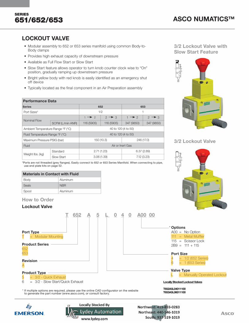
3/2 Lockout Valve with Slow Start Feature
3/2 Lockout Valve
Materials in Contact with FluidBody Aluminum
Seals NBR
Spool Aluminum
• Modular assembly to 652 or 653 series manifold using common Body-to-Body clamps
• Provides high exhaust capacity of downstream pressure• Available as Full Flow Start or Slow Start• Slow Start feature allows operator to turn knob counter clock wise to “On”
position, gradually ramping up downstream pressure• Bright yellow body with red knob is easily identified as an emergency shut
off device• Typically located as the final component in an Air Preparation assembly
* If multiple options are required, please use the online CAD configurator on the websiteto generate the part number (www.asco.com), or consult factory.
LOCKOUT VALVE
*
Performance DataSeries 652 653
Port Sizes* 1/2 1
Nominal Flow1 2 2 3 1 2 2 3
SCFM (L/min ANR) 116 (5905) 116 (5905) 347 (9850) 347 (9850)
Ambient Temperature Range °F (°C) 40 to 120 (4 to 50)
Fluid Temperature Range °F (°C) 40 to 120 (4 to 50)
Maximum Pressure PSIG (bar) 150 (10.3) 246 (17.0)
Fluid Air or Inert Gas
Weight Ibs. (kg)Standard 2.71 (1.23) 6.37 (2.89)
Slow Start 3.06 (1.39) 7.12 (3.23)
* Ports are not threaded (grey flanges). Easily connect to 652 or 653 Series Manifold. When connecting to pipe,use end plate kits on page 52.
Locally Stocked Lockout Valves
T652A5L04011100T653A5L06011100

SERIES
651/652/653 ASCO NUMATICS™
All manifolds come assembled and fully tested to your configuration.If additional support is required in the middle of a manifold. Please specify kit number P699AT502467001. This kit contains one Wall/Panel Bracket (also referred to as support bracket or mounting bracket). This bracket can be installed at the factory or ordered separately as a kit. This kit contains two screws, which allows customers to easily attach the bracket to the back of any of the Body-to-Body clamps in the manifold assembly. After selecting the top level assembly part number, please refer to each of the How to Order charts within this catalog to determine the specific product that is required in the manifold assembly. The How to Order charts are located on the following pages:
1 Conforms to ISO standards 1179-1
Air Flow DirectionL = Configure Air Flow P(1) Left - P(2) RightR = Configure Air Flow P(1) Right - P(2) Left
End Plate Port Size0 = None2 = 1/4 (651 Series)4 = 1/2 (652 Series)6 = 1 (653 Series)7 = 1-1/4 (653 Series)
L (653)L (651/652)
FC
Mounting Type0 = No MountingC = End Plates, Body-to-Body Assembly
Clamps & Wall/Panel BracketsF = End Plates and Body-to-Body
Assembly ClampsL = Side Mounting Brackets
OptionsA00 = No Options117 = ATEX Zones 1–21
Number of StationsA = 1 K = 11B = 2 L = 12C = 3 M = 13D = 4 N = 14E = 5 O = 15F = 6 P = 16G = 7 Q = 17H = 8 R = 18I = 9 S = 19J = 10 T = 20
Product TypeS = FRL Assembly
RevisionA
Product Series651652653
Port Type8 = NPTFG = ISO 228/1-GJ = ISO 7/1 Rc
8 651 A S L D 2 C 0 0 A00
How to Order - Air Preparation Manifold AssembliesAIR PREPARATION MANIFOLD ASSEMBLIES
1
Particulate Filter Page 4Coalescing Filter Page 8Regulator Page 12Manifold Regulator Page 16Particulate Filter/Regulator Page 19Coalescing Filter/Regulator Page 23
Lubricator Page 27Shut Off Isolation Valve Page 30Slow Start/Quick Exhaust Valve Page 33Diverter Block Page 36Lockout Valve Page 38

SERIES
651/652/653ASCO NUMATICS™
1
2
3
4
5
12 3
4 5
6
If multiple options are required, please use the online CAD configurator on the website to generate the part number (www.asco.com), or consult factory.
Example #2The following example assembly includes five stations of the 651 series products and side mounting brackets. The manifold air flow is from Right-to-Left. Port type is ISO 228/1-G. Port size is 1/4. The Lubricator is configured with an Electronic Liquid Level Indicator (option 108). The Shut Off Isolation Valve uses a combination option (270), which is configured when you use a Metal Muffler (111) and a Low Profile Gauge that requires a Right-to-Left flow (123). The Coalescing Filter/Regulator also uses a combination option. In this case, a combination option (243) includes a Key Lockable Handle (104) and a Low Profile Gauge that requires a Right-to-Left flow (123).
How to Order - 651/652 Series Air Preparation Manifold AssembliesExample #1The following example assembly includes six stations of the 652 series products, manifold end plates with mounting brackets and an additional support bracket between station 1 and 2. The manifold air flow is from Left-to-Right. Port type is NPTF. Port size is 1/2.The regulator is configured for a bottom oriented pressure adjustment (option 122). The Shut Off Isolation Valve is configured with a Low Profile Gauge, with pressure range indicators.
Example OrderAssembly G651ASRE0L00A00 651 Series Air Prep AssemblyStation #5 G651AL0M2010800 651 Series LubricatorStation #4 G651AD002TA0000 651 Series Diverter BlockStation #3 G651ACDM2F243GA 651 Series Coalescing Filter-RegulatorStation #2 G651ABBM2JA000A 651 Series Particulate FilterStation #1 G651A3M02F27000 651 Series Shut Off Isolation Valve
Assembled
Example OrderAssembly 8652ASLF4C00A00 652 Series Air Prep AssemblyStation #1 8652A3M04H11100 652 Series Shut Off Isolation Valve
P699AT502467001 Support BracketStation #2 8652ABBP4JA000N 652 Series Particulate FilterStation #3 8652AFDM4FA000A 652 Series Coalescing FilterStation #4 8652AR004F122G0 652 Series RegulatorStation #5 8652AD004TA0000 652 Series Diverter BlockStation #6 8652A6S74FA00F1 652 Series Slow Start/Quick
Exhaust Solenoid Valve Assembled

ASCO (USA) | Tel (1) 888-686-2842 | [email protected] | www.ASCO.com
Netherlands (31) 33-277-7911Singapore (65) 6556-1100South Korea (82) 2-3483-1570Spain (34) 942-87-6100United Kingdom (44) 1695-713600
France (33) 2-37-24-42-24Germany (49) 7237-9960India (91) 44-39197300Italy (39) 02-356931Japan (81) 798-65-6361Mexico (52) 55-5809-5640
Australia (61) 2-9-451-7077Brazil (55) 11-4208-1700Canada (1) 519-758-2700China (86) 21-3395-0000Czech Republic (420) 235-090-061Dubai - UAE (971) 4-811-8200
Global Contacts