air slide table · my = 1 x 9.8 (10 + 30)/1000 = 0.39 a3 = 30 may = 1 x 1 x 18 = 18 mymax = 18 k =...
TRANSCRIPT

Functional optionAdjuster optionSymmetric type
Body mounting taps
High precision, compact design
Positioning hole
Workpiece mountingtaps
Improved strength
Dual rods
Integrating table with guide rail
Recirculating linear guide
Wide Variety of Option
Positioning hole
Auto switch mounting groove
Body mounting through-hole
Application Example
�����
MXQ12-30
������
������������ ����������
�����������
0.035
��
������ ���������
±0.08
±��
����
46
!�
������
30
�
"#����� ������
86
$�
Series MXQ
Air Slide Table
%6, %8, %12, %16, %20, %25
Comparison of MXQ and MXS &��'
Wide variety of adjuster option
(����#�� )��*�����
��+����� �������������
,�� ����� +���
�-��� �+��� �+���+����
&,-���� ��� ��� )��� �+..��'
/)��� ��� �+��+� �. ���#�������� ���������
��� ���� ������ �+��� ����* �������� �. ����������� ��������� �����
Improved load resistance0��� ���������� ������� �+���� ��� �-�����#� �-������
.����� �� ������ ����� ����� ������� ���� ������ ����
Symmetric type is
also standardized.1#������� .�� ��� ������
1+�� �)������ ��� �� ��+���� �� ����#��
���#���� �� ��� ���� �. ��� ���� )���� ����
�� ��� �����+���
���� �. ����������� ��������� �����
�����+�������� .��
��+����� �� ��� ���� ���
���� �����#���
��+����� �� �������� .���
� �����������
1�2+���� ������ ��� .+������ ������ ��� �� ��������
��� ����*� ��2+����
��� ����* ��������
��� �+..�� ���������
��� ��� ���*
1-��� ������ ����
1. Lateral mounting
(Body tapped)
2. Lateral mounting
(Body through-hole)
3. Vertical mounting
(Body tapped)
1� 3�-�� .�� ���*���
��� �������
4�� ����������� �. ������� �� � ���#����
$5
MXH
MXU
MXS
MXQ
MXF
MXW
MXJ
MXP
MXY
MTS
Individual
-X�
D-�
-X�

With Buffer Mechanism With End Lock
Axial Piping Type
Application Example
Buffer mechanism in operational condition
Normal
condition
Series Variations
Locked
MXQ6L
MXQ8L
MXQ12L
MXQ16L
MXQ20L
MXQ25L
MXQ 6
MXQ 8
MXQ12
MXQ16
MXQ20
MXQ25
Standard type Symmetric type
Model
10 20 30 40 50 75 100 125 150
Rubberstopper
Shock absorber
Metalstopper
Adjuster option
Standard stroke (mm)
Auto switch
(mm)
6
8
12
16
20
25
Lock pistonSpring
Unlocked
Cylinder air
supply port
Speed controller
Functional OptionAdjuster Option
Air Slide Table Series MXQ
Bore size
Ext
ensi
on
en
d
Retr
act
ion
en
d
Bot
h en
ds
Ext
ensi
on
end
Retr
act
ion
en
d
Bot
h en
ds
Ext
ensi
on
en
d
Retr
act
ion
en
d
Bot
h en
ds
Functional option
With
buf
fer
With
end
lock
Axia
lpi
ping
type
Reed auto switch
• D-A9�
• D-A9�V
Solid state auto switch
• D-M9�
• D-M9�V
2-color indication
solid state auto switch
• D-M9�W
• D-M9�WV
Adjuster at extension end Retraction end adjuster
� Rubber stopperStandard stroke adjuster
� Shock absorberFor use in harsh conditions.Absorbs the impact at the stroke end forsmooth stopping. Improved stopping accuracy.
� Metal stopperImproved stopping accuracy.Without cushioning function for use with light loads and low speeds.
Three different types of adjusting bolt have been standardized for front end rear and double end adjusters and cushion mechanisms.
� Protects workpieces and tools, etc., by eliminating impact at the end of the extension stroke.
� Buffer unit is auto switch capable.
Auto switchNormally OFF ∗
ON is buffer in operation.( )
Bufferstroke
Magnet
Magnet
Auto switchNormally ON∗
OFF is buffer in operation.( )
∗ The normally ON/OFF setting is changed by
changing the direction of the auto switch
mounting.
In workpiece insertion processes when there is
a problem such as faulty positioning, the buffer
mechanism absorbs the shock from the
workpiece impact to prevent damage.
Air gripper
Workpiece
NG
Buffermechanism
� Holds the cylinder’s home position to prevent dropping of the workpiece even if the air supply is cut off.
� Centralized piping in axial direction to maintain clear space around the body.
89
MXH
MXU
MXS
MXQ
MXF
MXW
MXJ
MXP
MXY
MTS
Individual
-X�
D-�
-X�

Model Selection Step Formula/Data Selection Example
Operating Conditions
Kinetic Energy
Load Factor
3-1 Load Factor of Load Mass
3-2 Load Factor of the Static Moment
3-3 Load Factor of Dynamic Moment
3-4 Sum of the Load Factors
1
2
3
L2+
A5
L3
L1
Series MXQ
Model Selection
Enumerate the operating
conditions considering the
mounting position and workpiece
configuration.
• Model to be used
• Type of cushion
• Workpiece mounting position
• Mounting orientation
• Average speed Va (mm/s)
• Load mass W (kg): Fig. (1)
• Overhang Ln (mm) Fig. (2)
Cylinder: MXQ16-50
Cushion: Rubber stopper
Workpiece table mounting
Mounting: Horizontal wall mounting
Average speed: Va = 300 [mm/s]
Load mass: W = 1 [kg]
L1 = 10 mm
L2 = 30 mm
L3 = 30 mm
Find the kinetic energy E (J) of the
load.
Find the allowable kinetic energy
Ea (J).
Confirm that the kinetic energy of
the load does not exceed the
allowable kinetic energy.
Ea = K • E max
1 V 2E = —— • W (————) 2 1000
Collision speed V = 1.4 • Va —— ∗
Workpiece mounting coefficient K: Fig. (3)
Max. allowable kinetic energy Emax: Table (1)
Kinetic energy (E) ≤ Allowable kinetic energy (Ea)
∗) Correction factor
(Reference
values)
1 420 2E = —— x 1 (————) = 0.088 2 1000
V = 1.4 x 300 = 420
Ea = 1x 0.11 = 0.11
Can be used based on E = 0.088 ≤ Ea = 0.11
Find the allowable load mass Wa (kg).Note) No need to consider this load
factor in the case of using
perpendicularly in a vertical
position. (Define α1 =0.)
Find the load factor of the load
weight α1.
Wa = K • β • Wmax
Workpiece mounting coefficient K: Fig. (3)
Allowable load weight coefficient β: Graph (1)
Max. allowable load mass Wmax: Table (2)
α1 = W/Wa
Wa = 1 x 1 x 4 = 4
K = 1
β = 1
Wmax = 4
α1 = 1/4 = 0.25
Find the static moment M (N·m).
Find the allowable static moment
Ma (N·m).
Find the load factor α2 of the static moment.
M = W x 9.8 (Ln + An)/1000
Correction value of moment center position distance An: Table (3)
Ma = K • γ • Mmax
Workpiece mounting coefficient K: Fig. (3)
Allowable moment coefficient γ: Graph (2)
Maximum allowable moment Mmax: Table (4)
α2 = M/Ma
Examine My.
My = 1 x 9.8 (10 + 30)/1000
= 0.39
A3 = 30
May = 1 x 1 x 18 = 18
Mymax = 18
K = 1 γ = 1
α2 = 0.39/18 = 0.022
RollingYawing
Examine Mr.
Mr = 1 x 9.8 (30 + 10.5)/1000
= 0.39
A6 = 10.5
Mar = 36
Mrmax = 36
K = 1
γ = 1
α'2 = 0.39/36 = 0.011
Find the dynamic moment Me (N·m).
Find the allowable dynamic moment Mea (N·m).
Find the load factor α3 of the dynamic moment.
(Ln + An)Me = 1/3 • We x 9.8 ————— 1000
Collision equivalent to impact We = δ • W • V
δ: Bumper coefficient
Rubber stopper without adjuster = 4/100
Shock absorber = 1/100
Metal stopper= 16/100
Correction value of moment center position distance An: Table (3)
Mea = K • γ • Mmax
Workpiece mounting coefficient K: Fig. (3)
Allowable moment coefficient γ: Graph (2)
Max. allowable moment Mmax: Graph (4)
α3 = Me/Mea
Examine Mep. (30 + 10.5)Mep = 1/3 x 16.8 x 9.8 x ——————— = 2.2 1000 We = 4/100 x 1 x 420 = 16.8 A2 = 10.5Meap = 1 x 0.7 x 18 = 12.6 K = 1 γ = 0.7Mpmax = 18α3 = 2.2/12.6 = 0.17
Examine Mey. (30 + 24.5)Mey = 1/3 x 16.8 x 9.8 x ——————— = 3.0 1000 We=168 A4 = 24.5Meay = 12.6 (Same value as Meap)
α'3 = 3.0/12.6 = 0.24
Pitching
Yawing
Use is possible if the sum of the load factors does not exceed 1. Σαn = α1 + α2 + ·········· + αn ≤ 1
Σαn = α1 + α2 + α'2 + α3 + α'3
= 0.25 + 0.022 + 0.011 + 0.17 + 0.24 = 0.693 ≤ 1
And it is possible to use.
90

������
An (n = 1 to 6)
E
Emax
Ln (n = 1 to 3)
M (Mp, My, Mr)
Ma (Map, May, Mar)
Me (Mep, Mey)
Mea (Meap, Meay)
Mmax (Mpmax, Mymax, Mrmax)
V
���� ���
����� ��� ���� � ���� �� � ���� ��� ��� ���
��� �� ����
�������� ��� �� ����
�������
� � �� ���� ��� �� !�� "���#
�������� � � �� ���� ��� �� !�� "���#
������� ���� ��� �� !��#
�������� ������� ���� ��� �� !��#
$�%���� �������� ���� ��� �� !�� "���#
��������� ���
Symbol
MXQ 6
MXQ 8
MXQ12
MXQ16
MXQ20
MXQ25
$���
&'
&()
*('
)(+
&,
&-
,*
&('
'(+
'(.
'()
'(,
'(*
.' &'' *'' ,'' .'' +''
&('
'(+
'(.
'()
'(,
'(*
.' &'' *'' ,'' .'' +''
W
W
$/0 1
$/0 2
$/0&*
$/0&1
$/0*'
$/0*.
$���
&'
&)(.
&1(.
*&
*+
*-(.
,.(.
����� ��� ���� � ���� �� � ���� ��� ��� ��� �"� � 3���� �*#(#
MXQ 6
MXQ 8
MXQ12
MXQ16
MXQ20
MXQ25
$���
'(1
&
*
)
1
-
MXQ 6
MXQ 8
MXQ12
MXQ16
MXQ20
MXQ25
$���
�������� ��� �� ����
4� ��� ��5�� �"���� � ����
'('&2
'('*+
'('..
'(&&
'(&1
'(*)
$�%���� �������� ���� ����
W
W
K=1
K=0.6
W
Mp
6& �&
W
Mp
6& �*
Mep
�*
6,
Mey
6*
�)
W
My
6* �,
W
My
6* �)
W
Mr
6, �.
W
Mr
6, �1
'('&2
'('*+
'('..
'(&&
'(&1
'(*)
����� �������
7
'('.)
'(&&
'(**
'(,*
'()2
$ �� � ����
'(''-
'('&,
'('*+
'('..
'('2'
'(&*
��5�� � �� ���
A1, A3
� ��� ���# �* �) �. �1
*'
&)(.
&1(.
*&
*+
*-(.
,.(.
,'
&)(.
&2(.
*&
*+
*-(.
,.(.
)'
&2(.
*'(.
*.
*+
*-(.
,.(.
.'
&2(.
*2
*.
,'
,,(.
),
+.
7
*2(.
,)
,,
,+(.
),
&''
7
7
,)
)*(.
.,(.
.'
&*.
7
7
7
)*(.
..
1)
&.'
7
7
7
7
.1(.
1)
1
+
-
&'(.
&)
&1(.
&,(.
&1
&-(.
*)(.
,'
,+
&,(.
&1
&-(.
*)(.
,'
,+
1
+
-
&'(.
&)
&1(.
� ��� ���#
*'
&()
*('
)(+
&,
&-
,*
,'
&()
*(2
)(+
&,
&-
,*
)'
*(2
,(+
+(*
&,
&-
,*
.'
*(2
+(-
+(*
&2
*+
.*
+.
7
+(-
&.
*,
,1
.*
&''
7
7
&.
)*
2)
+2
&*.
7
7
7
)*
2)
&)'
&.'
7
7
7
7
2)
&)'
&'
,(.
.(&
&&
,&
)+
2&
*'
,(.
.(&
&&
,&
)+
2&
,'
,(.
1('
&&
,&
)+
2&
)'
.(&
1(-
&,
,&
)+
2&
.'
.(&
+()
&,
,1
.+
&&'
+.
7
+()
&)
)&
11
&&'
&''
7
7
&)
)&
+.
&,'
&*.
7
7
7
)&
+.
&,'
&.'
7
7
7
7
+.
&,'
�� ��8!�� ���� 9 $���%8$���%
� ��� ���#
"��� ���� 9 $���%
Caution :� ��%���� ���� ��� ��� �� � �� � ���� �� *'' ��8�(
W
Fig. (1) Load Mass: W (kg)
;� # ;� �� � �������
��� ���� �� �� �� � ��� �
����� ������������� �� �
�� ���� ���� ���(
Fig. (2) Overhang: Ln (mm), Correction Value of Moment Center Position Distance: An (mm)
�� �� ���� !�� ���� "��� ����
Fig. (3) Workpiece Mounting Coefficient: K
:��� ���� ���
<�� ��� ���� ���
� �
��
��
�
�
���
��
���
��
�
;� # � � �� ���� 9 $��� ���� � �� ����� �
������� ���� 9 $��� ���� � �� ����� ��� ��������� �� � � ����
Table (1) Allowable Kinetic Energy: Emax (J) Table (2)Maximum Allowable Load Mass: Wmax (kg)
Table (3) Correction Value of Moment Center Position Distance: An (mm)
;� # 3�� �* �) �. ��� �1 �� �� �� ����� �� � ����� � ����� �� � � � ���(
Table (4) Maximum Allowable Moment: Mmax (N·m)
>��
��
?
?
��
;@�
;@�
;@�
;@�
;@�
��8�
������
Va
W
Wa
We
Wmax
���K
���� ���
����� ���
6��� ����
�������� ���� ����
4��� A������ � �����
$�%( �������� ���� ����
6��� �� ��
�������� ���� ���� ������
�������� ���� ������
4������ ���� ��� ������
>��
��8�
��
��
��
��
7
7
7
7
Graph (1) Allowable Load Mass Coefficient: �
����
��
��
���
��
���
��
��
��
9�
����� ��� B� ���8�#
Graph (2) Allowable Moment Coefficient: �
����
��
��
��
�
�
��
��
��
9�
����� ��� B� ���8�# ��������� ��� B ���8�#
;� # >� � ����� ��� ��� ������� ��� � � ��
���� (
>� � ��������� ��� ��� ������� ���
������� ���� (
-&
Air Slide Table Series MXQ
MXH
MXU
MXS
MXQ
MXF
MXW
MXJ
MXP
MXY
MTS
Individual
-X�
D-�
-X�
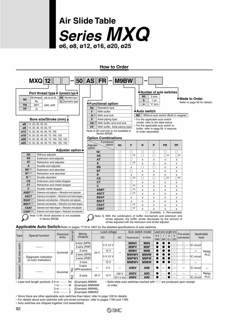
How to Order
ø6
ø8
ø12
ø16
ø20
ø25
MXQ 12 50 M9BWAS FR
Nil
L
Symmetric typePort thread type
Nil
TN
TF
M thread
Rc
NPT
G
ø6 to ø16
ø20, ø25
Without adjuster
Extension end adjuster
Retraction end adjuster
Double end adjuster
Extension end absorber
Retraction end absorber
Double absorber
Extension end metal stopper
Retraction end metal stopper
Double metal stopper
Extension end adjustor + Retraction end absorber
Extension end adjustor + Retraction end metal stopper
Extension end absorber + Retraction end adjuster
Extension end absorber + Retraction end metal stopper
Extension end metal stopper + Retraction end adjuster
Extension end metal stopper + Retraction end absorber
Nil
Refer to page 93 for details.
Nil
Nil F R P FR FP
Option Combinations
AS
AT
A
BS
BT
B
CS
CT
C
ASBT
ASCT
BSAT
BSCT
CSAT
CSBT
Functional option
A96V
A93V
A90V
M9NV
M9PV
M9BV
M9NWV
M9PWV
M9BWV
A96
A93
A90
M9N
M9P
M9B
M9NW
M9PW
M9BW
Type Special function
—
24 V
24 V
3-wire (NPN)
3-wire (PNP)
2-wire
3-wire (NPN)
3-wire (PNP)
2-wire
Load voltage
DC AC
Auto switch model Lead wire length (m)
Perpendicular In-line0.5
(Nil)
5
(Z)
—
100 V
100 V or less
—
—
—
—
—
—
—
1
(M)
—
—
—
IC circuit
—
IC circuit
IC circuit
—
IC circuit
—
—
—
—
5 V
12 V
5 V,12 V
12 V
5 V,12 V
12 V
3
(L)
Standard type
Symmetric type
Bore size/Stroke (mm)
10, 20, 30, 40, 50
10, 20, 30, 40, 50, 75
10, 20, 30, 40, 50, 75, 100
10, 20, 30, 40, 50, 75, 100, 125
10, 20, 30, 40, 50, 75, 100, 125, 150
10, 20, 30, 40, 50, 75, 100, 125, 150
Adjuster option
AS
AT
A
BS (1)
BT (1)
B (1)
CS
CT
C
ASBT (1)
ASCT
BSAT (1)
BSCT (1)
CSAT
CSBT (1)
Note 1) W/ shock absorber is not available
in Series MXQ6.
Number of auto switches2 pcs.
1 pc.
“n” pcs.
Nil
S
n
Made to Order
Auto switchNil Without auto switch (Built-in magnet)
∗ For the applicable auto switch model, refer to the table below.
∗ For the applicable auto switch to buffer, refer to page 95. It requires to order separately.
Standard type
With buffer
With end lock
Axial piping type
With buffer and end lock
With buffer, Axial piping type
Nil
F
R (2)
P
FR (2)
FP
Note 2) W/ end lock is not available in Series MXQ6.
Adjusteroption
Functionaloption
Note 3) With the combination of buffer mechanism and extension end stroke adjuster, the buffer stroke decreases by the amount of stroke adjusted with the extension end stroke adjuster.
: Available, : Not available
Applicable Auto Switch/Refer to pages 1719 to 1827 for the detailed specifications of auto switches.
Electricalentry
Reed s
witc
hS
olid
sta
te s
witc
h
Diagnostic indication(2-color indication)
Grommet
Grommet Ye
sN
oYes
Indi
cato
r lig
ht
Wiring (Output)
3-wire
(NPN equivalent)
2-wire
Pre-wired
connector
Applicable
load
Relay,
PLC
Relay,
PLC
∗ Lead wire length symbols: 0.5 m ········· Nil (Example) M9NW
1 m ·········· M (Example) M9NWM
3 m ·········· L (Example) M9NWL
5 m ·········· Z (Example) M9NWZ
∗ Solid state auto switches marked with “ ” are produced upon receipt
of order.
∗ Since there are other applicable auto switches than listed, refer to page 128 for details.
∗ For details about auto switches with pre-wired connector, refer to pages 1784 and 1785.
∗ Auto switches are shipped together (not assembled).
92
Air Slide Table
Series MXQø6, ø8, ø12, ø16, ø20, ø25
(3) (3) (3)
(3) (3)
(3)
(3)
(3)
(3)
(3)
(3)
(3)
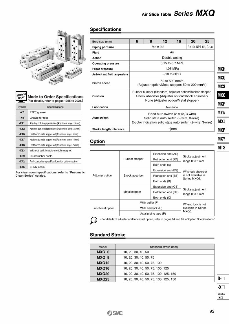
Bore size (mm)
Piping port size
Fluid
Action
Operating pressure
Proof pressure
Ambient and fluid temperature
Specifications
Air
Double acting
0.15 to 0.7 MPa
1.05 MPa
–10 to 60°C
50 to 500 mm/s(Adjuster option/Metal stopper: 50 to 200 mm/s)
Rubber bumper (Standard, Adjuster option/Rubber stopper)
Shock absorber (Adjuster option/Shock absorber)
None (Adjuster option/Metal stopper)
Non-lube
Reed auto switch (2-wire, 3-wire)
Solid state auto switch (2-wire, 3-wire)
2-color indication solid state auto switch (2-wire, 3-wire)
mm
M5 x 0.8
Piston speed
MXQ 6
MXQ 8
MXQ12
MXQ16
MXQ20
MXQ25
Standard Stroke
Standard stroke (mm)
10, 20, 30, 40, 50
10, 20, 30, 40, 50, 75
10, 20, 30, 40, 50, 75, 100
10, 20, 30, 40, 50, 75, 100, 125
10, 20, 30, 40, 50, 75, 100, 125, 150
10, 20, 30, 40, 50, 75, 100, 125, 150
Cushion
Lubrication
Auto switch
Stroke length tolerance
6 8 12 16 20 25
Rc 1/8, NPT 1/8, G 1/8
Adjuster option
Option
Extension end (AS)
Retraction end (AT)
Both ends (A)
Extension end (BS)
Retraction end (BT)
Both ends (B)
Extension end (CS)
Retraction end (CT)
Both ends (C)
Rubber stopper
Shock absorber
Metal stopper
Functional option
With buffer (F)
With end lock (R)
Axial piping type (P)
Stroke adjustment
range 0 to 5 mm
W/ shock absorber
is not available in
Series MXQ6.
Stroke adjustment
range 0 to 5 mm
W/ end lock is not
available in Series
MXQ6.
Model
Symbol Specifications
PTFE grease
Grease for food
Adjusting bolt, long specification (Adjustment range: 15 mm)
Adjusting bolt, long specification (Adjustment range: 25 mm)
Heat treated metal stopper bolt (Adjustment range: 5 mm)
Heat treated metal stopper bolt (Adjustment range: 15 mm)
Heat treated metal stopper bolt (Adjustment range: 25 mm)
Without built-in auto switch magnet
Fluororubber seals
Anti-corrosive specifications for guide section
EPDM seals
-X7
-X9
-X11
-X12
-X16
-X17
-X18
-X33
-X39
-X42
-X45
+1 0
Made to Order Specifications(For details, refer to pages 1955 to 2021.)
For clean room specifications, refer to “Pneumatic Clean Series” catalog.
∗ For details of adjuster and functional option, refer to pages 94 and 95 in “Option Specifications”.
93
Air Slide Table Series MXQ
MXH
MXU
MXS
MXQ
MXF
MXW
MXJ
MXP
MXY
MTS
Individual
-X�
D-�
-X�

Symmetric type
Adjustment range
Nil
-X11
-X12
MXQ
� ��
�� ��
�� ��
6
8
12
16
20
25
12 X11AS
�����
� ���
��
��
���
���
���
���
Theoretical Output
���
��
�
��
��
��
��
��
��
���
��
���
���
���� ��������
�� ��������
����� ���������
� ����� ���!���
� ����� ����"�� �#���
6
8
12
16
�
�
�
�
�$%
&'
�(
��
�$%
&'
���
(�
�$%
&'
���
�(�
�$%
&'
���
���
���
�(
��
��
��
��
��
���
��
���
���
���
��(
���
��
�(
��
��
��
��
���
���
���
���
���
���
���
��
��
��
��
���
��
���
���
���
���
���
�(�
���
��
��
��
��
���
���
���
���
�((
���
���
���
��(
��
��
(�
��
���
���
���
���
���
���
��(
���
MXQ 6
MXQ 8
MXQ12
MXQ16
MXQ20
MXQ25
#��)
����� ����*� ����
20 ��
25 ��
�$%
&'
���
�(�
�$%
&'
���
(��
&'�$%
+�����) ,�� -� �. �/"���� � ���
��
���
���
���
���
����
�(��
��
���
�(�
���
���
����
�(��
��
���
���
���
�(�
����
�(��
��
���
���
���
(��
����
����
��
���
���
���
���
����
����
(�
0
���
���
����
�(��
�(��
���
0
0
(��
����
����
����
���
0
0
0
����
����
����
���
0
0
0
0
����
�(��
�
��
��
��
��
���
�
��
��
��
��
���
��
��
(�
���
���
���
0
��
���
���
���
���
How to Order Stroke Adjuster (Accessory)
Mass
L
Nil
L
AS
AT
BS
BT
CS
CT
����*� �/"����� �� �
Option Specifications
0
��
�(
(�
�(�
���
0
��
��
��
���
���
��
��
��
��
���
���
�
��
��
��
��
���
The dual rod ensures an output twice that of existing cylinders. �'�
'���� %-������!�) �"� "� �'� 1 �����"�� �#��� 2 ����� ���� �����
�"33�� ��� ��
42����� � �����!��� �
�-�!* �3���3��
42����� � �����!��� �
#���) ��� ��
42����� � �����!��� �
� �
+2��) � � �5 �
��6 ����*� �����
7��- �
)�!*7��- 3"..��
42��� .�� � ���
�� 8 ��� �
�� 8 ��� �
�� 8 ��� �
�� 8 ��� �
��� 8 ��� �
��� 8 ��� �
Stroke Adjustment Range of Adjuster Option �&���!�) .�� �2����� � �����!��� ���
%5 �
�"33�� ��� ��
7��- �-�!* �3���3��
#���) ��� ��
� �� � ��
��.�� �� �-� ������� � � � ����
� �� � ��
� � ����) ,�� �/"����� �� � �/"���� ��� �:��)�3)�,��- �"33�� ��� �� � ����) ��� ���
Adjuster option
42����� �
�����!��� �
42����� �
�����!��� �
42����� �
�����!��� �
�"33��
��� ��
�-�!*
�3���3��
#���)
��� ��
����� �5 �
�5������! �5 �
Applicable bore size'��� �� ;<�� ��/"��� �� �6 �� ��� �� �� �:��)�3)� � ������ #<=��
'��� �� ;<�� � ;<�� ��� �� �:��)�3)� ,��- �-�!* �3���3���
'��� �� 7> �-�!* �3���3�� �� �� �:��)�3)� � ������ #<=��
'��� �� ?�� �������@ ��.�� �� � �� ��� �� ����
?�� �-� �5������! �5 �@ ��.�� �� �-� �2����) ������� �5������!�))5�
��5������! �5 � �� ,-�� �-� ���!��� �. �-� �/"��� 3�)� �� ��:������
��
Series MXQ

Table Accuracy
MXQ6
Shock Absorber Specifications
Model MXQ6
6
3
6
MXQ8
8
5
8
MXQ12
12
10
13
MXQ16
16
13
17
MXQ20
20
17
25
MXQ25
25
21
29
5 10
Model MXQ8
8
25
MXQ12
12
60
MXQ16
16
110
MXQ20
20
160
MXQ25
25
250
50 to 500 mm/s
RB0805
MXQ8
0.98
5
80
245
1.96
3.83
15
RB0806
MXQ12
RB1007
MXQ16
RB1411
MXQ20
RB1412
MXQ25
2.94
6
80
245
1.96
4.22
15
5.88
7
50 to 500
70
422
–10 to 60
4.22
6.86
25
14.7
11
45
814
6.86
15.30
65
19.6
12
45
814
6.86
15.98
65
With End Lock Specifications
Buffer Mechanism Specifications
Applicable Auto Switch to Buffer
–4 to 0
MXQ8
–4 to 0
MXQ12
–6 to 0
MXQ16
–10 to 0
MXQ20
–12 to 0
MXQ25
–14 to 0
MXQ 6
MXQ 8
MXQ12
MXQ16
MXQ20
MXQ25
10
0.025
0.025
0.03
0.035
0.04
0.045
20
0.03
0.03
0.03
0.035
0.04
0.045
30
0.035
0.035
0.035
0.04
0.04
0.045
40
0.04
0.04
0.04
0.045
0.045
0.05
50
0.045
0.055
0.045
0.05
0.055
0.06
75
—
0.065
0.065
0.065
0.07
0.07
100
—
—
0.075
0.08
0.095
0.09
125
—
—
—
0.095
0.105
0.115
150
—
—
—
—
0.125
0.125
WA
BC
M
0.06
0.04
0.02
0 50 100 150
Radial
clearance
Shock absorber model
Applicable slide table
Max. energy absorption (J)
Stroke absorption (mm)
Max. collision speed (mm/s)
Max. operating frequency (cycle/min)
Max. allowable thrust (N)
Ambient temperature range (°C)
Spring force (N)
Mass (g)
Extended
Retracted
Note) The shock absorber service life is different from that of the MXQ cylinder depending on operating conditions. Refer to the RB Series Specific Product Precautions for the replacement period.
Bore size (mm)
Piston speed
Holding force (N)
Note) For caution on end lock, refer to page 132.
Bore size (mm)
Piston speed
Buffer stroke (mm)
Bufferstrokeload (N)
Strokeat 0 (mm)Maximumstroke
50 to 500 mm/s (Horizontal mounting 50 to 300 mm/s)
Note 1) For caution on handling the one with buffer mechanism,refer to page 132.
Note 2) The buffer stroke decreases by the amount of stroke adjusted with the extension end stroke adjuster.
Type model
D-M9BV
D-M9NV
D-M9PV
Solid state
switch
Specifications
With light, 2-wire
With light, 3-wire, Output: NPN
With light, 3-wire, Output: PNP
Electrical entry direction
Vertical
∗ The auto switch for buffer must be ordered separately.
Model
B side parallelism to A side
B side traveling parallelism to A side
C side perpendicularity to A side
M dimension tolerance
W dimension tolerance
Radial internal clearance (µm)
Refer to Table (1).
Refer to Graph (1).
0.05 mm
±0.08 mm (±0.1 mm) ∗1
±0.1 mm
∗1) ±0.1 mm for 75 mm or longer stroke
Table (1) B Side Parallelism to A Side (mm)
(mm)
ModelStroke (mm)
Graph (1) B Side Traveling Parallelism to A Side
Tra
velin
g p
ara
llelis
m (
mm
)
Stroke (mm)
Traveling parallelism:The amount of deflection on a dial gauge when
the table travels a full stroke with the body secured
on a reference base surface.
95
Air Slide Table Series MXQ
MXH
MXU
MXS
MXQ
MXF
MXW
MXJ
MXP
MXY
MTS
Individual
-X�
D-�
-X�

Table Deflection (Reference Values)
Lr=40 mm
Lr=70 mm
Lr=90 mm
0.03
0.02
0.01
10 20 30
20 40 60
0.03
0.02
0.01
20 40 60 80 100
0.01
0.02
0.03
0.04
0.03
0.02
0.01
10 20 30
0.04
0.02
20 40 60
0.04
0.06
20 40 60 80 100
0.10
0.02
0.04
0.06
0.08
0.015
0.010
40 80 120
0.005
0.010
40 80 120
0.005
0.012
0.008
120
0.016
0.004
0.020
16040 80
0
0
0
0
0
0
0
0
0
ø8
ø12
ø6
ø8
ø12
ø6
ø8
ø12
F A
Lr
F
MXQ6-10
MXQ6-20
MXQ6-30MXQ6-50
MXQ6-40
MXQ6-10
MXQ6-20
MXQ6-30
MXQ6-50
MXQ6-40
MXQ6-10MXQ6-20MXQ6-30 MXQ6-50
MXQ6-40MXQ6-10MXQ6-20MXQ6-30 MXQ6-50
MXQ6-40
MXQ12-10
MXQ12-30
MXQ12-20
MXQ12-50
MXQ12-40
MXQ12-75
MXQ12-100
MXQ12-75
MXQ12-10
MXQ12-40
MXQ12-20
MXQ12-30
MXQ12-100
MXQ12-75
MXQ12-10
MXQ12-40
MXQ12-20
MXQ12-30
MXQ12-100
MXQ12-50
MXQ12-30MXQ12-20MXQ12-10
MXQ12-100MXQ12-75MXQ12-50MXQ12-40
MXQ12-30MXQ12-20MXQ12-10
MXQ8-20
MXQ8-10
MXQ8-30MXQ8-40
MXQ8-50
MXQ8-75MXQ8-75
MXQ8-10MXQ8-20
MXQ8-50MXQ8-40
MXQ8-75
MXQ8-10MXQ8-20 MXQ8-30
MXQ8-50MXQ8-40
ø60.05
MXQ8-10
MXQ8-30
MXQ8-75
MXQ8-20
MXQ8-40
MXQ8-50
Table displacement due topitch moment loadTable displacement when loads are applied to the
section marked with the arrow at the full stroke.
Table displacement due toyaw moment loadTable displacement when loads are applied to the
section marked with the arrow at the full stroke.
Table displacement due toroll moment loadTable displacement of section A when loads are
applied to the section F with the slide table retracted.
Ta
ble
dis
pla
ce
me
nt
am
ou
nt
(mm
)
Ta
ble
dis
pla
ce
me
nt
am
ou
nt
(mm
)
Ta
ble
dis
pla
ce
me
nt
am
ou
nt
(mm
)
Ta
ble
dis
pla
ce
me
nt
am
ou
nt
(mm
)
Ta
ble
dis
pla
ce
me
nt
am
ou
nt
(mm
)
Ta
ble
dis
pla
ce
me
nt
am
ou
nt
(mm
)
Ta
ble
dis
pla
ce
me
nt
am
ou
nt
(mm
)
Ta
ble
dis
pla
ce
me
nt
am
ou
nt
(mm
)
Ta
ble
dis
pla
ce
me
nt
am
ou
nt
(mm
)
Load (N) Load (N) Load (N)
Load (N) Load (N) Load (N)
Load (N) Load (N) Load (N)
96
Series MXQ

Lr=120 mm
Lr=160 mm
Lr=200 mm
0.06
0.04
0.02
50 100 200
100 200 300
0.06
0.04
0.02
100 200 300 400 500
0.04
0.06
0.08
0.10
0.08
0.04
50 100 200
0.04
100 200 300
0.08
0.12
100 200 300 400 500
0.12
0.04
0.08
0.04
0.03
100 200 300
0.02
0.04
100 200 300
0.02
0.04
0.02
600
0.06
0.08
800200 400
0
0
0
0
0
0
0
0
0
ø20
ø25
ø16
ø20
ø25
ø16
ø20
ø25
ø160.12
F A
Lr
F
MXQ16-20MXQ16-30
MXQ16-10
MXQ16-40
MXQ16-50
MXQ16-100MXQ16-125
MXQ16-75
MXQ16-20MXQ16-30
MXQ16-10
MXQ16-40
MXQ16-50
MXQ25-100MXQ25-125MXQ25-150
MXQ25- 50MXQ25- 75
MXQ25-100MXQ25-125MXQ25-150
MXQ25- 50MXQ25- 75
MXQ25- 10MXQ25- 20MXQ25- 30MXQ25- 40
MXQ16-30
MXQ16-50
MXQ16-20
MXQ16-10
MXQ16-40
MXQ16-75MXQ16-100MXQ16-125
MXQ16-10
MXQ16-20
MXQ16-100
MXQ16-30
MXQ16-50
MXQ16-75MXQ16-40
MXQ16-125
MXQ20-10
MXQ20-50
MXQ20-125
MXQ20-20
MXQ20-75MXQ20-30
MXQ20-150
MXQ20-40
MXQ20-100
MXQ25-10
MXQ25-30MXQ25-50MXQ25-125
MXQ25-150MXQ25-100
MXQ25-75
MXQ25-20
MXQ25-40
MXQ25-10
MXQ20-125MXQ20-150
MXQ20-40MXQ20-75
MXQ20-125MXQ20-150
MXQ20-50
MXQ20-10
MXQ20-30
MXQ20-20
MXQ20-100
MXQ20-40MXQ20-75
150 150
0.01
400
0.06
400 500 600
0.08
MXQ25-125
MXQ25-150
MXQ25-50
MXQ25-20
MXQ25-30MXQ25-125MXQ25-100MXQ25-75
MXQ25-150
MXQ25-50
MXQ25-20
MXQ25-40
MXQ25-30
0.02
MXQ20-50
MXQ20-100MXQ20-125MXQ20-150
MXQ20-10MXQ20-20MXQ20-30
MXQ20-50MXQ20-75
MXQ20-40
The graphs below show the table displacement when the static moment
load is applied to the table. The graphs do not show the loadable mass.
Refer to the Model Selection for the loadable mass.
Table displacement due topitch moment loadTable displacement when loads are applied to the
section marked with the arrow at the full stroke.
Table displacement due toyaw moment loadTable displacement when loads are applied to the
section marked with the arrow at the full stroke.
Table displacement due toroll moment loadTable displacement of section A when loads are
applied to the section F with the slide table retracted.
Ta
ble
dis
pla
ce
me
nt
am
ou
nt
(mm
)
Load (N)
Ta
ble
dis
pla
ce
me
nt
am
ou
nt
(mm
)
Load (N)
Ta
ble
dis
pla
ce
me
nt
am
ou
nt
(mm
)
Load (N)
Ta
ble
dis
pla
ce
me
nt
am
ou
nt
(mm
)
Load (N)
Ta
ble
dis
pla
ce
me
nt
am
ou
nt
(mm
)
Load (N)
Ta
ble
dis
pla
ce
me
nt
am
ou
nt
(mm
)
Load (N)
Ta
ble
dis
pla
ce
me
nt
am
ou
nt
(mm
)
Load (N)
Ta
ble
dis
pla
ce
me
nt
am
ou
nt
(mm
)
Load (N)
Ta
ble
dis
pla
ce
me
nt
am
ou
nt
(mm
)
Load (N)
97
Air Slide Table Series MXQ
MXH
MXU
MXS
MXQ
MXF
MXW
MXJ
MXP
MXY
MTS
Individual
-X�
D-�
-X�

Dimensions: MXQ6
Model F
22
25
21
26
27
N
4
4
6
6
6
G
6
13
—
11
21
H
23
26
—
28
28
NN
2
2
3
3
3
I
9
9
9
16
9
J
17
27
37
48
65
K
21.5
31.5
41.5
51.5
61.5
Z
41.5
51.5
61.5
79.5
89.5
M
42
52
62
80
90
ZZ
48
58
68
86
96
MXQ6-10
MXQ6-20
MXQ6-30
MXQ6-40
MXQ6-50
Basic style
4 x M2.5 x 0.45 thread depth 3.5
4 x M2.5 x 0.45 thread depth 2.5
Adjuster at extension end
(mm)
GA
13
13
29
39
49
HA
16
26
20
28
28
Z
ZZ
Max. 10 (Retraction end adjuster)6IJ
10.5 5.5
3
2 6
131620
3 x M3 x 0.5 thread depth 5
15.5
3.5
2 x M2.5 x 0.45 thread depth 3
Operating port 2 x M5 x 0.8
5.5
10
13
.5
20
4
9
4
N x M3 x 0.5 thread depth 4 Note 1) Note 2)
14
27
1.5
31
5.5 3
15
12
18.2
0.3
F
11
5 M
12.5K
6.53
3.5
20
10.5 5.5
ø6.5
ø7
ø3.2
ø3.2
ø6.5
ø7
G
B
H
A
4
HA GA
BA
12
0.5
∗ For detailed dimensions about the stroke adjuster,
refer to the option for the stroke adjuster.
Rubber stopper (Refer to page 122.)
Metal stopper (Refer to page 125.)
Note 1) If long bolts are used, they can touch the guide block and cause malfunction, etc.Refer to the Specific Product Precautions.
Note 2) Since the table is made of a magnetic substance, it could become magnetized if touched by a magnet, etc. This could cause auto switch malfunction.
19.5 (Adjuster at extension end)
6 (
Adju
ste
r a
t e
xte
nsio
n e
nd)
ø3 depth 2.5+0.03 0
Retraction end adjuster
3
depth
2.5
+0
.03
0
2N
– 1 x F
Bottom view of MXQ6-30
(NN – 1) x H
ø3H9 depth 2.5+0.025 0
3H
9 d
epth
2.5
+0
.02
5 0
NN x M4 x 0.7 thread depth 8
Section AA Section BB
Note)Note)
Note) Refer to the bottom view of MXQ6-30.
98
Series MXQ

� � �� � ��� ��� ��� �
��
���
�������� ��� � � �� � ���
�
� ��
��
���
����
����
�
���
��
��
����
With buffer (ø6): MXQ6-��F
� ��� ��������� �� �� ���� �� ����� ������
Axial piping type (ø6): MXQ6-��P
� ��� ��������� �� �� ���� �� ����� ������
��
Air Slide Table Series MXQ
MXH
MXU
MXS
MXQ
MXF
MXW
MXJ
MXP
MXY
MTS
Individual
-X�
D-�
-X�

4 x M2.5 x 0.45 thread depth 3.5
4 x M2.5 x 0.45 thread depth 2.56.5
Z
ZZ
6IJ3
2 6
131620
3 x M3 x 0.5 thread depth 5
15.5
3.5
2 x M2.5 x 0.45 thread depth 3Operating port 2 x M5 x 0.8
5.5
10
13
.5
20
4
9
4
N x M3 x 0.5 thread depth 4 Note 1) Note 2)
14 27
1.5
31
5.5 3
15
12
18
.20
.3
F
11
5 M
12.5K
3 3.5
20
10.5 5.5
ø3.2
ø6.5 ø7
10.5 5.5
ø3.2
ø6.5 ø7
NN x M4 x 0.7 thread depth 8
G
B
H
A
4
HA GA
BA
12
Dimensions: MXQ6L/Symmetric Type
Model F
22
25
21
26
27
N
4
4
6
6
6
G
6
13
—
11
21
H
23
26
—
28
28
NN
2
2
3
3
3
I
9
9
9
16
9
J
17
27
37
48
65
K
21.5
31.5
41.5
51.5
61.5
Z
41.5
51.5
61.5
79.5
89.5
M
42
52
62
80
90
ZZ
48
58
68
86
96
MXQ6L-10
MXQ6L-20
MXQ6L-30
MXQ6L-40
MXQ6L-50
Basic style
(mm)
GA
13
13
29
39
49
HA
16
26
20
28
28
0.5
∗ For detailed dimensions about the stroke adjuster,
refer to the option for the stroke adjuster.
Rubber stopper (Refer to page 122.)
Metal stopper (Refer to page 125.)
Note 1) If long bolts are used, they can touch the guide block and cause malfunction, etc.Refer to the Specific Product Precautions.
Note 2) Since the table is made of a magnetic substance, it could become magnetized if touched by a magnet, etc. This could cause auto switch malfunction.
2N
– 1 x F
6 (
Ad
juste
r a
t exte
nsio
n e
nd)
Adjuster at extension end
19.5 (Adjuster at extension end)
ø3 depth 2.5+0.03 0
Retraction end adjuster
3 de
pth
2.5
+0
.03
0
Max. 10
(Retraction end adjuster)
Bottom view of MXQ6L-30
ø3H9 depth 2.5+0.025 0
(NN – 1) x H
3H
9 d
epth
2.5
+0
.02
5 0
Section AA Section BB
Note) Refer to the bottom view of MXQ6L-30.
100
Series MXQ
Note) Note)

� � �� � ��� ��� ��� �
�������� ��� � � �� � ���
�
�
���
����
��
���
���
��
��
��
��
����
����
�
� ��� ��������� �� �� ���� �� ����� ������
With buffer (ø6): MXQ6L-��F
� ��� ��������� �� �� ���� �� ����� ������
���
Air Slide Table Series MXQ
Axial piping type (ø6): MXQ6L-��P
MXH
MXU
MXS
MXQ
MXF
MXW
MXJ
MXP
MXY
MTS
Individual
-X�
D-�
-X�

4 x M3 x 0.5 thread depth 4
NA x M3 x 0.5 thread depth 3.5
Adjuster at extension end
Retraction end adjuster
Z
ZZ
Max. 11 (Retraction end adjuster)8IJ
12.5 5.7
3.5
2 7
62327
3 x M4 x 0.7 thread depth 6
16
.54
16
2 x M3 x 0.5 thread depth 4
Operating port 2 x M5 x 0.8
6.5
12
24
5
10
4
16
32
1
36
6.5 3.5
17
15
21.2
0.3
F
12
6 M
14.6K
73.8
14.6KA
73.8
4
23
ø6.5
ø7ø3.2
12.5 5.7
ø6.5
ø7ø3.2
NN x M4 x 0.7 thread depth 8
G
B
H
A
4
HA GAB
A
14
Dimensions: MXQ8
Model F
25
25
26
32
46
50
N
4
4
6
6
6
6
G
7
14
—
8
8
31
H
25
28
—
31
29
30
NN
2
2
3
3
4
4
I
11
10
12
14
13
12
J
17
28
40
52
78
105
K
23.5
33.5
43.5
53.5
63.5
88.5
Z
45.5
55.5
69.5
83.5
108.5
134.5
M
46
56
70
84
109
135
ZZ
53
63
77
91
116
142
MXQ8-10
MXQ8-20
MXQ8-30
MXQ8-40
MXQ8-50
MXQ8-75
Basic style
(mm)
GA
13
14
29
39
37
61
HA
19
28
27
31
58
60
NA
4
4
4
4
8
8
KA
—
—
—
—
82.5
112.5
0.7
∗ For detailed dimensions about the stroke adjuster,
refer to the option for the stroke adjuster.
Rubber stopper (Refer to page 122.)
Metal stopper (Refer to page 125.)
Note 1) If long bolts are used, they can touch the guide block and cause malfunction, etc.Refer to the Specific Product Precautions.
Note 2) Since the table is made of a magnetic substance, it could become magnetized if touched by a magnet, etc. This could cause auto switch malfunction.
22.5 (Adjuster at extension end)ø3 depth 3
+0.03 0
N x M3 x 0.5 thread depth 5 Note 1) Note 2)
6.5
(A
dju
ste
r a
t exte
nsio
n e
nd)
2N
– 1 x F
3
depth
3+
0.0
3
0
Bottom view of MXQ8-30
(NN – 1) x H
ø3H9 depth 3+0.025 0
3H
9 d
epth
3+
0.0
25
0
Section AA Section BB
Note) Refer to the bottom view of MXQ8-30.
Note) Note)
102
Series MXQ

��������� ��
��
��������� ��
��
� � �� � ��� ����� ���� ���
���
����
�
��������� ���� � � �� � ���
��������� ���� � � �� � ���
��
� ����
��
�
��
� ����� � �����
����
���
����
����
�
����
��
���
��
��
��
����
�
����
Stroke Adjustable Range !!�
� ����� �!������� ��� ��� ��!� �� "���� ��#$��
���� ��
%���& �"���"�� �� ��������� ��
%���& �"���"�� �� ���������� ��
���� ��
����� ���� ���� ��� ��� �( ��� ����& �"���"�� )��� *�$$ "� ������ ���� ���� �( ��� ��"$��
With buffer (ø8): MXQ8-��F
� ����� �!������� ��� ��� ��!� �� "���� ��#$��
With end lock (ø8): MXQ8-��R
� ����� �!������� ��� ��� ��!� �� "���� ��#$��
Axial piping type (ø8): MXQ8-��P
� ����� �!������� ��� ��� ��!� �� "���� ��#$��
���
Air Slide Table Series MXQ
With shock absorber (ø8): MXQ8-��BS/BT/B
MXH
MXU
MXS
MXQ
MXF
MXW
MXJ
MXP
MXY
MTS
Individual
-X�
D-�
-X�

4 x M3 x 0.5 thread depth 4
NA x M3 x 0.5 thread depth 3.5
Z
ZZ
8IJ3.5
2 762327
3 x M4 x 0.7 thread depth 6
16.5
4
2 x M3 x 0.5 thread depth 4Operating port 2 x M5 x 0.8
6.5
12 16
24
5
10
4
N x M3 x 0.5 thread depth 5 Note 1) Note 2)
16
32
1
36
6.5 3.5
17
15
21.2
0.3
F
12
6 M
14.6KA
14.6K
3.8 7
3.8 7
4
23
12.5 5.7
ø3.2
ø6.5 ø7
12.5 5.7
ø3.2
ø6.5 ø7
NN x M4 x 0.7 thread depth 8
G
BHA
4
HA GA
BA
14
Dimensions: MXQ8L/Symmetric Type
Model F
25
25
26
32
46
50
N
4
4
6
6
6
6
G
7
14
—
8
8
31
H
25
28
—
31
29
30
NN
2
2
3
3
4
4
I
11
10
12
14
13
12
J
17
28
40
52
78
105
K
23.5
33.5
43.5
53.5
63.5
88.5
Z
45.5
55.5
69.5
83.5
108.5
134.5
M
46
56
70
84
109
135
ZZ
53
63
77
91
116
142
MXQ8L-10
MXQ8L-20
MXQ8L-30
MXQ8L-40
MXQ8L-50
MXQ8L-75
Basic style
(mm)
GA
13
14
29
39
37
61
HA
19
28
27
31
58
60
NA
4
4
4
4
8
8
KA
—
—
—
—
82.5
112.5
0.7
∗ For detailed dimensions about the stroke adjuster,
refer to the option for the stroke adjuster.
Rubber stopper (Refer to page 122.)
Metal stopper (Refer to page 125.)
Note 1) If long bolts are used, they can touch the guide block and cause malfunction, etc.Refer to the Specific Product Precautions.
Note 2) Since the table is made of a magnetic substance, it could become magnetized if touched by a magnet, etc. This could cause auto switch malfunction.
22.5 (Adjuster at extension end)
Adjuster at extension end
6.5
(A
dju
ste
r a
t exte
nsio
n e
nd) 2
N– 1 x F
3 d
ep
th 3
+0
.03
0
ø3 depth 3+0.03 0
Retraction end adjuster
Max. 11 (Retraction end adjuster)
Bottom view of MXQ8L-30
ø3H9 depth 3 +0.025 0
(NN – 1) x H
3H
9
d
epth
3+
0.0
25
0
Section AA Section BB
Note)Note)
Note) Refer to the bottom view of MXQ8L-30.
104
Series MXQ

� � �� � ��� �� � ��� �
���
��
����
�
���� ��� ��� � � �� � ���
���� ��� ��� � � �� � ���
��
� ����
��
�
��
� ����
����
���
����
����
�
����
��
���
��
��
��
����
�
����
�������� ���
��
��� ���� ���
��
Axial piping type (ø8): MXQ8L-��P
Stroke Adjustable Range !!�
� ��� ��!������� �� � � !� � " ��� �#$�
� �� ��
%��& "���"�� �������� ���
� �� ��
� ����
%��& "���"�� ��� ���� ���
���� ��� � �� �( � ���& "���"�� )�� *�$$ "� ���� � �( � "$��
� ��� ��!������� �� � � !� � " ��� �#$�
� ��� ��!������� �� � � !� � " ��� �#$�
� ��� ��!������� �� � � !� � " ��� �#$�
���
Air Slide Table Series MXQ
With shock absorber (ø8): MXQ8L-��BS/BT/B
With buffer (ø8): MXQ8L-��F
With end lock (ø8): MXQ8L-��R
MXH
MXU
MXS
MXQ
MXF
MXW
MXJ
MXP
MXY
MTS
Individual
-X�
D-�
-X�

4 x M4 x 0.7 thread depth 6
NA x M4 x 0.7 thread depth 4
Z
ZZ
10IJ
16 8
4.75
2 9.5
92939
3 x M5 x 0.8 thread depth 8
1
29.5 (Adjuster at extension end)
85
2 x M4 x 0.7 thread depth 6 Operating port 2 x M5 x 0.8
8.5
14
.5
19
.5
29
5
13
5
N x M4 x 0.7 thread depth 5 Note 1) Note 2)
20 39
2.5
46
8 4.5
22
20
27.2
0.3
F
16
8 M
18.5K
8.55
18.5KA
8.55
4.8
30
ø8.5
ø9
ø4.2
16 8
ø8.5
ø9
ø4.2
NN x M5 x 0.8 thread depth 10
G
B
HA
5
HA GA
BA
19
Dimensions: MXQ12
Model F
28
28
38
34
34
36
36
N
4
4
4
6
6
8
10
G
18
18
20
—
9
23
12
H
32
32
40
—
39
36
36
NN
2
2
2
3
3
4
5
I
12
12
14
15
13
17
17
J
34
34
42
58
70
110
135
K
26.5
36.5
46.5
56.5
66.5
91.5
116.5
Z
66
66
76
93
103
147
172
M
67
67
77
94
104
148
173
ZZ
76
76
86
103
113
157
182
MXQ12- 10
MXQ12- 20
MXQ12- 30
MXQ12- 40
MXQ12- 50
MXQ12- 75
MXQ12-100
(mm)
GA
18
18
20
38
48
59
84
HA
32
32
40
39
39
72
72
NA
4
4
4
4
4
8
8
KA
—
—
—
—
—
117.5
142.5
1
Basic style
∗ For detailed dimensions about the stroke adjuster,
refer to the option for the stroke adjuster.
Rubber stopper (Refer to page 122.)
Metal stopper (Refer to page 125.)
Max. 13 (Retraction end adjuster)
Note 1) If long bolts are used, they can touch the guide block and cause malfunction, etc.Refer to the Specific Product Precautions.
Note 2) Since the table is made of a magnetic substance, it could become magnetized if touched by a magnet, etc. This could cause auto switch malfunction. Adjuster at extension end
ø4H9 depth 4+0.030 0
Retraction end adjuster
10 (
Adju
ste
r a
t exte
nsio
n e
nd
)
2N
– 1 x F
4H
9
d
epth
4+
0.0
30
0
Bottom view of MXQ12-40
(NN – 1) x H
ø4H9 depth 4+0.030 0
4H
9
d
ep
th 4
+0
.03
0 0
Section AA Section BB
Note)Note)
Note) Refer to the bottom view of MXQ12-40.
106
Series MXQ
� � �� � ��� �� � ��� �
��
���
��
�
���� ��� ��� � � �� � ���
��
� ��
����
��
����
��
���
����
��
����
����
���
��
��
��
����
�
��
�������� ���
��
��� ���� ���
��
Stroke Adjustable Range� !
� ��� �� ������� �� � � � � " ��� �#$��
� �� ��
%��& "���"�� �������� ��� %��& "���"�� ��� ���� ���
� �� ��
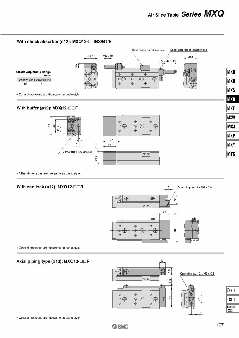
With buffer (ø12): MXQ12-��F
� ��� �� ������� �� � � � � " ��� �#$��
With end lock (ø12): MXQ12-��R
� ��� �� ������� �� � � � � " ��� �#$��
� ��� �� ������� �� � � � � " ��� �#$��
Axial piping type (ø12): MXQ12-��P
���� ��� ��� � � �� � ���
���
Air Slide Table Series MXQ
With shock absorber (ø12): MXQ12-��BS/BT/B
MXH
MXU
MXS
MXQ
MXF
MXW
MXJ
MXP
MXY
MTS
Individual
-X�
D-�
-X�

Max. 13 (Retraction end adjuster)
10IJ
4 x M4 x 0.7 thread depth 6
NA x M4 x 0.7 thread depth 4
Z
ZZ
4.75
2 9.5
92939
3 x M5 x 0.8 thread depth 8
18
5
2 x M4 x 0.7 thread depth 6Operating port 2 x M5 x 0.8
8.5
14
.5
19
.5
29
5
13
5N x M4 x 0.7 thread depth 5 Note 1) Note 2)
20
39
2.5
46
8 4.5
22
20
27.2
0.3
F
16
8 M
18.5KA
18.5K
5 8.5
5 8.5
4.8 30
16 8
ø4.2
ø8.5 ø9
16 8
ø4.2
ø8.5 ø9
NN x M5 x 0.8 thread depth 10
G
B
HA
5
HA GA
BA
19
Dimensions: MXQ12L/Symmetric Type
Model F
28
28
38
34
34
36
36
N
4
4
4
6
6
8
10
G
18
18
20
—
9
23
12
H
32
32
40
—
39
36
36
NN
2
2
2
3
3
4
5
I
12
12
14
15
13
17
17
J
34
34
42
58
70
110
135
K
26.5
36.5
46.5
56.5
66.5
91.5
116.5
Z
66
66
76
93
103
147
172
M
67
67
77
94
104
148
173
ZZ
76
76
86
103
113
157
182
MXQ12L- 10
MXQ12L- 20
MXQ12L- 30
MXQ12L- 40
MXQ12L- 50
MXQ12L- 75
MXQ12L-100
(mm)
GA
18
18
20
38
48
59
84
HA
32
32
40
39
39
72
72
NA
4
4
4
4
4
8
8
KA
—
—
—
—
—
117.5
142.5
1
Basic style
∗ For detailed dimensions about the stroke adjuster,
refer to the option for the stroke adjuster.
Rubber stopper (Refer to page 122.)
Metal stopper (Refer to page 125.)
Note 1) If long bolts are used, they can touch the guide block and cause malfunction, etc.Refer to the Specific Product Precautions.
Note 2) Since the table is made of a magnetic substance, it could become magnetized if touched by a magnet, etc. This could cause auto switch malfunction.
2N
– 1 x F
10 (
Adju
ste
r a
t exte
nsio
n e
nd)
29.5 (Adjuster at extension end)
ø4H9 depth 4+0.030 0
Adjuster at extension end
Retraction end adjuster
4H9
de
pth
4+
0.03
0 0
Bottom view of MXQ12L-40
4H
9 depth
4+
0.0
30
0
(NN – 1) x H
ø4H9 depth 4+0.030 0
Section AA Section BB
Note)Note)
Note) Refer to the bottom view of MXQ12L-40.
108
Series MXQ
� � �� � ��� �� � ��� �
���
��
��
�
���� ��� ��� � � �� � ���
���� ��� ��� � � �� � ���
��
� ��
����
��
����
��
���
����
��
����
����
���
��
��
��
����
�
��
�������� ���
��
��� ���� ���
��
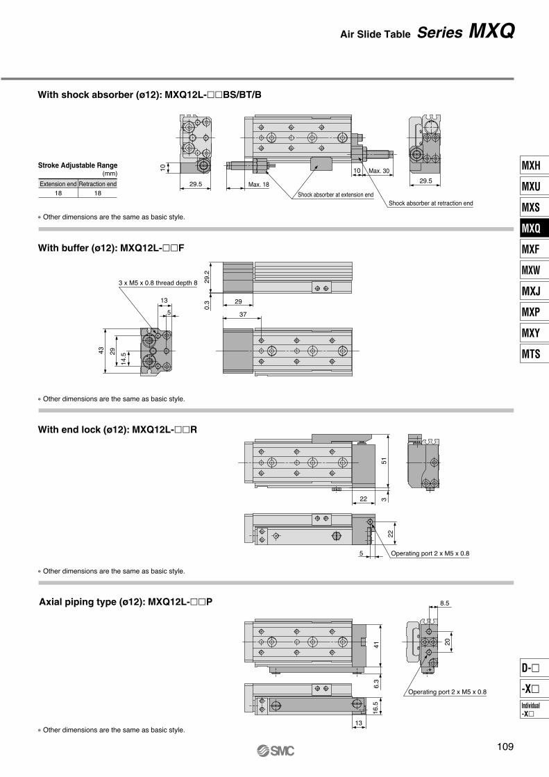
With shock absorber (ø12): MXQ12L-��BS/BT/B
Stroke Adjustable Range� !
� ��� �� ������� �� � � � � " ��� �#$��
� ��� �� ������� �� � � � � " ��� �#$��
� ��� �� ������� �� � � � � " ��� �#$��
� ��� �� ������� �� � � � � " ��� �#$��
� �� ��
%��& "���"�� �������� ���
%��& "���"�� ��� ���� ���
� �� ��
With buffer (ø12): MXQ12L-��F
With end lock (ø12): MXQ12L-��R
Axial piping type (ø12): MXQ12L-��P
���
Air Slide Table Series MXQ
MXH
MXU
MXS
MXQ
MXF
MXW
MXJ
MXP
MXY
MTS
Individual
-X�
D-�
-X�

4 x M5 x 0.8 thread depth 7
NA x M5 x 0.8 thread depth 6.5
Z
ZZ
12IJ
21 9
5.5
3 11
133545
3 x M6 x 1 thread depth 10
11
15.5
2 x M5 x 0.8 thread depth 8
Operating port 2 x M5 x 0.8
11
14
.5
24.5
29
6.5
14
6
N x M5 x 0.8 thread depth 6 Note 1) Note 2)
24 49
3.5
58
11 5.5
28
24
.5
33.7
0.3
F
21
10 M
21K
105.5
21KA
105.5
5.5
37
ø9.5
ø10.5
ø5.1
21 9
ø9.5
ø10.5
ø5.1
NN x M6 x 1 thread depth 12
G
B
HA
6
HA GA
BA
24
Dimensions: MXQ16
Model F
38
38
48
58
40
46
44
44
N
4
4
4
4
6
6
8
10
G
18
18
19
19
—
21
36
17
H
39
39
48
58
—
52
44
44
NN
2
2
2
2
3
3
4
5
I
12
12
12
12
20
15
18
23
J
40
40
50
60
68
105
145
165
K
28
38
48
58
68
93
118
143
Z
77
77
87
97
113
145
188
213
M
78
78
88
98
114
146
189
214
ZZ
89
89
99
109
125
157
200
225
MXQ16- 10
MXQ16- 20
MXQ16- 30
MXQ16- 40
MXQ16- 50
MXQ16- 75
MXQ16-100
MXQ16-125
(mm)
GA
18
18
19
19
48
73
80
105
HA
39
39
48
58
45
52
88
88
NA
4
4
4
4
8
8
8
8
KA
—
—
—
—
91
123
166
191
1
Basic style
∗ For detailed dimensions about the stroke adjuster,
refer to the option for the stroke adjuster.
Rubber stopper (Refer to page 122.)
Metal stopper (Refer to page 125.)
Max. 12 (Retraction end adjuster)
Note 1) If long bolts are used, they can touch the guide block and cause malfunction, etc.Refer to the Specific Product Precautions.
Note 2) Since the table is made of a magnetic substance, it could become magnetized if touched by a magnet, etc. This could cause auto switch malfunction.
36.5 (Adjuster at extension end)Adjuster at extension end
ø5H9 depth 5+0.030 0
Retraction end adjuster
12.5
(A
dju
ste
r a
t exte
nsio
n e
nd
)
2N
– 1 x F
5H
9
d
ep
th 5
+0
.03
0
0
Bottom view of MXQ16-50
(NN – 1) x H
ø5H9 depth 5+0.030 0
5H
9 depth
5+
0.0
30
0
Section AA Section BB
Note)Note)
Note) Refer to the bottom view of MXQ16-50.
110
Series MXQ

� � �� � � ���� � �� ��
��
���
����
� ����� �� � � �� � ���
� ����� �� � � �� � ���
����
��� ��
����
��
����
��
���
����
����
��
��
��
��
��
��
��
��
�
��
�������� ��
��
�������� ��
��
Stroke Adjustable Range� !
� ��� �� ������ � �� �� �� "���� ��#$�
� ��� �� ������ � �� �� �� "���� ��#$�
� ��� �� ������ � �� �� �� "���� ��#$�
� ��� �� ������ � �� �� �� "���� ��#$�
���� ��%���& �"��" �� ������� ��
���� ��
%���& �"��" �� ������� ��
With buffer (ø16): MXQ16-��F
With end lock (ø16): MXQ16-��R
Axial piping type (ø16): MXQ16-��P
���
Air Slide Table Series MXQ
With shock absorber (ø16): MXQ16-��BS/BT/B
MXH
MXU
MXS
MXQ
MXF
MXW
MXJ
MXP
MXY
MTS
Individual
-X�
D-�
-X�

12IJ
4 x M5 x 0.8 thread depth 7
NA x M5 x 0.8 thread depth 6.5
Z
ZZ
5.5
3 11
3 x M6 x 1 thread depth 10
111
5.5
2 x M5 x 0.8 thread depth 8 Operating port 2 x M5 x 0.8
11
14.5
24
.5
29
6.5
14
6
N x M5 x 0.8 thread depth 6 Note 1) Note 2)
24 49
3.5
58
11 5.5
28
24.5
33.7
0.3
21
10 M
21KA
21K
5.5 10
5.5 10
5.5 37
21 9
ø5.1
ø9.5
ø10.5
21 9
ø5.1
ø9.5
ø10.5
NN x M6 x 1 thread depth 12
G
BHA
6
HA GA
BA
24
Dimensions: MXQ16L/Symmetric Type
Model F
38
38
48
58
40
46
44
44
N
4
4
4
4
6
6
8
10
G
18
18
19
19
—
21
36
17
H
39
39
48
58
—
52
44
44
NN
2
2
2
2
3
3
4
5
I
12
12
12
12
20
15
18
23
J
40
40
50
60
68
105
145
165
K
28
38
48
58
68
93
118
143
Z
77
77
87
97
113
145
188
213
M
78
78
88
98
114
146
189
214
ZZ
89
89
99
109
125
157
200
225
MXQ16L- 10
MXQ16L- 20
MXQ16L- 30
MXQ16L- 40
MXQ16L- 50
MXQ16L- 75
MXQ16L-100
MXQ16L-125
(mm)
GA
18
18
19
19
48
73
80
105
HA
39
39
48
58
45
52
88
88
NA
4
4
4
4
8
8
8
8
KA
—
—
—
—
91
123
166
191
F
1
133545
Basic style
∗ For detailed dimensions about the stroke adjuster,
refer to the option for the stroke adjuster.
Rubber stopper (Refer to page 122.)
Metal stopper (Refer to page 125.)
Note 1) If long bolts are used, they can touch the guide block and cause malfunction, etc.Refer to the Specific Product Precautions.
Note 2) Since the table is made of a magnetic substance, it could become magnetized if touched by a magnet, etc. This could cause auto switch malfunction.
36.5 (Adjuster at extension end)
ø5H9 depth 5+0.030 0
12.5
(A
dju
ste
r a
t exte
nsio
n e
nd
)
2N
– 1 x F
5H9
de
pth
5+
0.03
0 0
Adjuster at extension end
Retraction end adjuster
Max. 12 (Retraction end adjuster)
ø5H9 depth 5+0.030 0
(NN – 1) x H
5H
9 depth
5+
0.0
30
0
Section AA Section BB
Bottom view of MXQ16L-50
Note)Note)
Note) Refer to the bottom view of MXQ16L-50.
112
Series MXQ

��
����
� � � � � �� �� � �� ��
���
��
����
�� ����� ��� � � � � ���
�� ����� ��� � � � � ���
����
��� ��
����
��
���
����
����
����
��
��
��
��
��
��
�
��
�� ����� ��
��
� ������ ��
��
With shock absorber (ø16): MXQ16L-��BS/BT/B
Stroke Adjustable Range� !
"���# �$���$ � � � ����� �� "���# �$���$ � � � ������ ��
� �� � �� ������ �� � �� �� $���� �%& �
� �� � �� ������ �� � �� �� $���� �%& �
� �� � �� ������ �� � �� �� $���� �%& �
� �� � �� ������ �� � �� �� $���� �%& �
With buffer (ø16): MXQ16L-��F
With end lock (ø16): MXQ16L-��R
Axial piping type (ø16): MXQ16L-��P
���
Air Slide Table Series MXQ
��� ��
��� ��
MXH
MXU
MXS
MXQ
MXF
MXW
MXJ
MXP
MXY
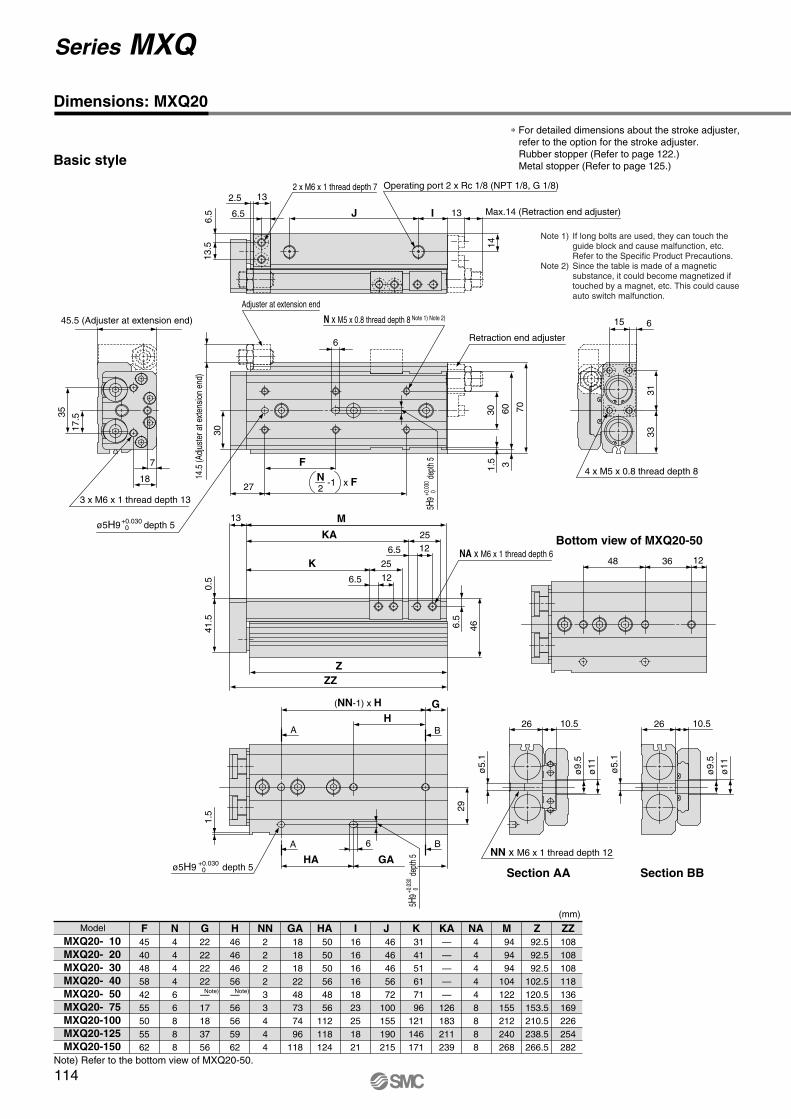
MTS
Individual
-X�
D-�
-X�
4 x M5 x 0.8 thread depth 8
NA x M6 x 1 thread depth 6
Z
ZZ
13IJ
26 10.5
6.5
2.5 13
123648
3 x M6 x 1 thread depth 13
1.5
13.5
6.5
2 x M6 x 1 thread depth 7 Operating port 2 x Rc 1/8 (NPT 1/8, G 1/8)
14
17.5
30
35
7
18
6
N x M5 x 0.8 thread depth 8 Note 1) Note 2)
30
1.5
60
3
70
15 6
33
31
41.5
0.5
F
27
13 M
25K
126.5
25KA
126.5
6.5
46
ø9.5
ø11
ø5.1
26 10.5
ø9.5
ø11
ø5.1
NN x M6 x 1 thread depth 12
G
B
HA
6
HA GA
BA
29
Dimensions: MXQ20
Model F
45
40
48
58
42
55
50
55
62
N
4
4
4
4
6
6
8
8
8
G
22
22
22
22
—
17
18
37
56
H
46
46
46
56
—
56
56
59
62
NN
2
2
2
2
3
3
4
4
4
I
16
16
16
16
18
23
25
18
21
J
46
46
46
56
72
100
155
190
215
K
31
41
51
61
71
96
121
146
171
Z
92.5
92.5
92.5
102.5
120.5
153.5
210.5
238.5
266.5
M
94
94
94
104
122
155
212
240
268
ZZ
108
108
108
118
136
169
226
254
282
MXQ20- 10
MXQ20- 20
MXQ20- 30
MXQ20- 40
MXQ20- 50
MXQ20- 75
MXQ20-100
MXQ20-125
MXQ20-150
(mm)
GA
18
18
18
22
48
73
74
96
118
HA
50
50
50
56
48
56
112
118
124
NA
4
4
4
4
4
8
8
8
8
KA
—
—
—
—
—
126
183
211
239
Basic style
∗ For detailed dimensions about the stroke adjuster,
refer to the option for the stroke adjuster.
Rubber stopper (Refer to page 122.)
Metal stopper (Refer to page 125.)
Max.14 (Retraction end adjuster)
Note 1) If long bolts are used, they can touch the guide block and cause malfunction, etc.Refer to the Specific Product Precautions.
Note 2) Since the table is made of a magnetic substance, it could become magnetized if touched by a magnet, etc. This could cause auto switch malfunction.
45.5 (Adjuster at extension end)
Adjuster at extension end
Retraction end adjuster
ø5H9 depth 5+0.030 0
14.5
(A
djus
ter
at e
xten
sion
end
)
2N
-1 x F
5H9
de
pth
5+0
.030
0
Bottom view of MXQ20-50
(NN-1) x H
ø5H9 depth 5+0.030 0
+0.0
30 0
Section AA Section BB
Note) Refer to the bottom view of MXQ20-50.
Note)Note)
5H9
de
pth
5
114
Series MXQ
3 x M6 x 1 thread depth 13
65
11.5
78.5
Operating port 2 x Rc 1/8 (NPT 1/8, G 1/8)
18
7 44.5
46.5
0.5 Note)
13
46.5
30.5
0.5
42.5
16
35
60
17
.5
20
33
26
14
32
8
34
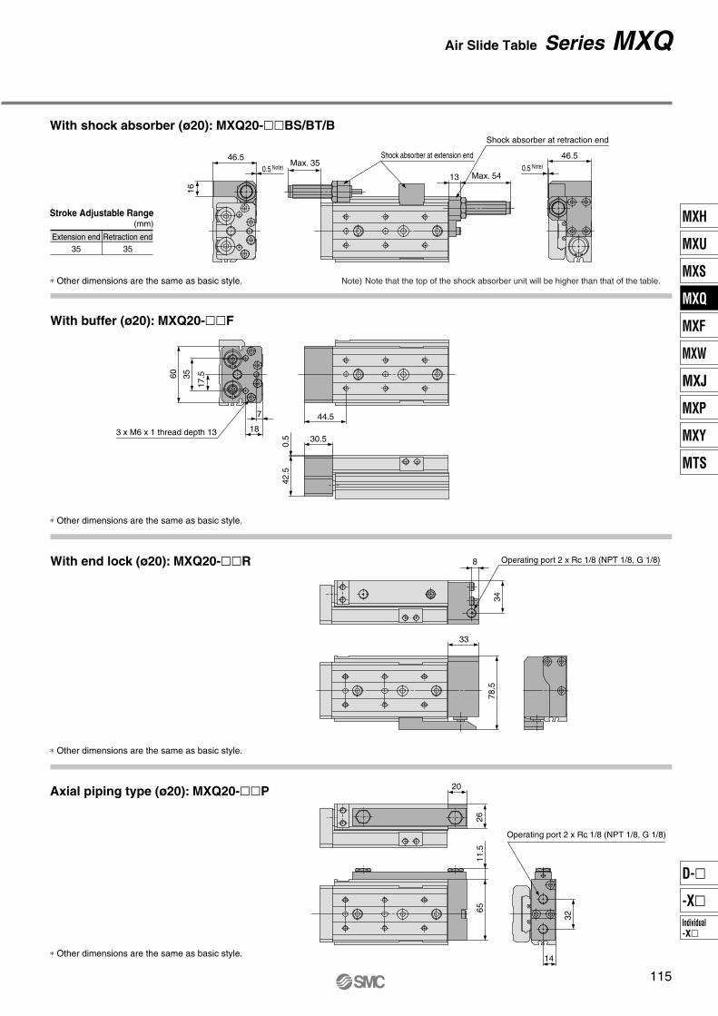
Extension end
35
Retraction end
35
Stroke Adjustable Range(mm)
∗ Other dimensions are the same as basic style.
∗ Other dimensions are the same as basic style.
∗ Other dimensions are the same as basic style.
∗ Other dimensions are the same as basic style.
Max. 35
Max. 54
Shock absorber at extension end
Shock absorber at retraction end
0.5 Note)
Note) Note that the top of the shock absorber unit will be higher than that of the table.
With buffer (ø20): MXQ20-��F
With end lock (ø20): MXQ20-��R
Operating port 2 x Rc 1/8 (NPT 1/8, G 1/8)
Axial piping type (ø20): MXQ20-��P
115
Air Slide Table Series MXQ
With shock absorber (ø20): MXQ20-��BS/BT/B
MXH
MXU
MXS
MXQ
MXF
MXW
MXJ
MXP
MXY
MTS
Individual
-X�
D-�
-X�

13IJ
4 x M5 x 0.8 thread depth 8
NA x M6 x 1 thread depth 6
Z
ZZ
6.5
2.5 13
123648
3 x M6 x 1 thread depth 13
1.5
13.5
6.5
2 x M6 x 1 thread depth 7
Operating port 2 x Rc 1/8 (NPT 1/8, G 1/8)
14
17
.5
35
30
7
18
6
N x M5 x 0.8 thread depth 8 Note 1) Note 2)
30
1.5
60
3
70
15 6
33
31
41
.50.5
F
27
13 M
25KA
25K
6.5 12
6.5 12
6.5 4
6
26 10.5
ø5.1
ø9.5
ø11
26 10.5
ø5.1
ø9.5
ø11
NN x M6 x 1 thread depth 12
G
BHA
6
HA GA
BA
29
Dimensions: MXQ20L/Symmetric Type
Model F
45
40
48
58
42
55
50
55
62
N
4
4
4
4
6
6
8
8
8
G
22
22
22
22
—
17
18
37
56
H
46
46
46
56
—
56
56
59
62
NN
2
2
2
2
3
3
4
4
4
I
16
16
16
16
18
23
25
18
21
J
46
46
46
56
72
100
155
190
215
K
31
41
51
61
71
96
121
146
171
Z
92.5
92.5
92.5
102.5
120.5
153.5
210.5
238.5
266.5
M
94
94
94
104
122
155
212
240
268
ZZ
108
108
108
118
136
169
226
254
282
MXQ20L- 10
MXQ20L- 20
MXQ20L- 30
MXQ20L- 40
MXQ20L- 50
MXQ20L- 75
MXQ20L-100
MXQ20L-125
MXQ20L-150
Basic style
(mm)
GA
18
18
18
22
48
73
74
96
118
HA
50
50
50
56
48
56
112
118
124
NA
4
4
4
4
4
8
8
8
8
KA
—
—
—
—
—
126
183
211
239
∗ For detailed dimensions about the stroke adjuster,
refer to the option for the stroke adjuster.
Rubber stopper (Refer to page 122.)
Metal stopper (Refer to page 125.)
Note 1) If long bolts are used, they can touch the guide block and cause malfunction, etc.Refer to the Specific Product Precautions.
Note 2) Since the table is made of a magnetic substance, it could become magnetized if touched by a magnet, etc. This could cause auto switch malfunction.
45.5 (Adjuster at extension end)
ø5H9 depth 5+0.030 0
Adjuster at extension end
14.5
(A
dju
ste
r at exte
nsio
n e
nd)
2N
– 1 x F
5H9
dep
th 5
+0.
030
0
Retraction end adjuster
Bottom view of MXQ20L-50
ø5H9 depth 5+0.030 0
5H
9 d
epth
5+
0.0
30
0
(NN – 1) x H Section AA Section BB
Max. 14 (Retraction end adjuster)
Note)Note)
Note) Refer to the bottom view of MXQ20L-50.
116
Series MXQ

��������� ��
��
��������� ��
��
����
����
��
� � �� � � ����� ���� ��
����
��
����
��������� ���� � � � ��� �� ! ���" # ���$
��������� ���� � � � ��� �� ! ���" # ���$
��
� %%��
%������ ����$ ��� ����$
%���
����
���
%���
��
�%
��
��
��
�
��
�%
With shock absorber (ø20): MXQ20L-��BS/BT/B
Stroke Adjustable Range�&&$
� ����� �&������� ��� ��� ��&� �� '���� ��()��
� ����� �&������� ��� ��� ��&� �� '���� ��()��
� ����� �&������� ��� ��� ��&� �� '���� ��()��
� ����� �&������� ��� ��� ��&� �� '���� ��()��
���� ��
���� �%
*���+ �'���'�� �� ��������� ��
*���+ �'���'�� �� ���������� ��
����$ ���� ���� ��� ��� �- ��� ����+ �'���'�� .��� /�)) '� ������ ���� ���� �- ��� ��')��
With buffer (ø20): MXQ20L-��F
With end lock (ø20): MXQ20L-��R
Axial piping type (ø20): MXQ20L-��P
���
Air Slide Table Series MXQ
MXH
MXU
MXS
MXQ
MXF
MXW
MXJ
MXP
MXY
MTS
Individual
-X�
D-�
-X�
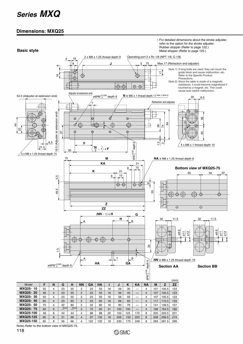
Z
ZZ
4 x M6 x 1 thread depth 10
NA x M8 x 1.25 thread depth 8
15IJ
32 11.5
8
4 16
225065
3 x M8 x 1.25 thread depth 15
1.5
16
82 x M8 x 1.25 thread depth 9 Operating port 2 x Rc 1/8 (NPT 1/8, G 1/8)
17
22
37
44
6.5
21.5
7
N x M6 x 1 thread depth 11 Note 1) Note 2)
36
1.5
74
3
84
20 6.5
40
38
49.5
0.5
F
30
15 M
31K
158
31KA
158
8
55
35
ø11
ø12
ø6.6
32 11.5
ø11
ø12
NN x M8 x 1.25 thread depth 16
G
BH
A
7
HA GA
BA
Dimensions: MXQ25
Model F
55
46
55
65
75
60
48
60
65
N
4
4
4
4
4
6
8
8
8
G
23
23
23
23
32
—
44
31
56
H
55
55
55
65
80
—
44
66
66
NN
2
2
2
2
2
3
4
4
4
I
16
16
16
16
16
31
20
18
18
J
56
56
56
66
90
100
150
205
230
K
35
45
55
65
75
100
125
150
175
Z
105.5
105.5
105.5
115.5
139.5
164.5
203.5
256.5
281.5
M
107
107
107
117
141
166
205
258
283
ZZ
123
123
123
133
157
182
221
274
299
MXQ25- 10
MXQ25- 20
MXQ25- 30
MXQ25- 40
MXQ25- 50
MXQ25- 75
MXQ25-100
MXQ25-125
MXQ25-150
Basic style
(mm)
GA
23
23
23
23
32
72
88
97
122
HA
55
55
55
65
80
65
88
132
132
NA
4
4
4
4
4
4
8
8
8
KA
—
—
—
—
—
—
170
223
248
ø6.6
∗ For detailed dimensions about the stroke adjuster,
refer to the option for the stroke adjuster.
Rubber stopper (Refer to page 122.)
Metal stopper (Refer to page 125.)
Max.17 (Retraction end adjuster)
Note 1) If long bolts are used, they can touch the guide block and cause malfunction, etc.Refer to the Specific Product Precautions.
Note 2) Since the table is made of a magnetic substance, it could become magnetized if touched by a magnet, etc. This could cause auto switch malfunction.
54.5 (Adjuster at extension end)Adjuster at extension end
ø6H9 depth 6+0.030 0
Retraction end adjuster
16.5
(A
dju
ste
r a
t exte
nsio
n e
nd
)
2N
– 1 x F
6H9
dep
th 6
+0.0
30 0
Bottom view of MXQ25-75
(NN – 1) x H
ø6H9 depth 6+0.030 0
6H
9 d
epth
6+
0.0
30
0
Section AA Section BB
Note) Refer to the bottom view of MXQ25-75.
118
Series MXQ
Note)Note)

� � �� � ��� �� �� � �� �
��
��
�
��
�� ����� ��� � � �� ��� ���� ��� ! ���"
�� ����� ��� � � �� ��� ���� ��� ! ���"
���
#� $
�
��
�
��
$�
��
�
�#
�
����
��
�$
��
��
��
�$
�
�$
%� �&��� ��
�
� ������ ��
�
With shock absorber (ø25): MXQ25-��BS/BT/B
Stroke Adjustable Range�''"
���� �� (���) �*&��* � � � �&��� ��
(���) �*&��* � � � ������ ��
���� �
� �� � ��' �&���& �� � &�' �& *�&�� &+, �
� �� � ��' �&���& �� � &�' �& *�&�� &+, �
� �� � ��' �&���& �� � &�' �& *�&�� &+, �
� �� � ��' �&���& �� � &�' �& *�&�� &+, �
With buffer (ø25): MXQ25-��F
With end lock (ø25): MXQ25-��R
Axial piping type (ø25): MXQ25-��P
���
Air Slide Table Series MXQ
MXH
MXU
MXS
MXQ
MXF
MXW
MXJ
MXP
MXY
MTS
Individual
-X�
D-�
-X�

15IJ
4 x M6 x 1 thread depth 10
NA x M8 x 1.25 thread depth 8
Z
ZZ
8
4 16
7
225065
3 x M8 x 1.25 thread depth 15
1.5
16
8
2 x M8 x 1.25 thread depth 9 Operating port 2 x Rc 1/8 (NPT 1/8, G 1/8)
22
37
44
6.521.5
N x M6 x 1 thread depth 11 Note 1) Note 2)
36
1.5
74
3
84
20 6.5
40
38
49.5
0.5
F
30
15 M
31KA
31K
8 15
8 15
8
55
32 11.5
ø11
ø12
32 11.5
ø11
ø12
NN x M8 x 1.25 thread depth 16
G
BHA
7
HA GA
BA
35
17
Dimensions: MXQ25L/Symmetric Type
Model F
55
46
55
65
75
60
48
60
65
N
4
4
4
4
4
6
8
8
8
G
23
23
23
23
32
—
44
31
56
H
55
55
55
65
80
—
44
66
66
NN
2
2
2
2
2
3
4
4
4
I
16
16
16
16
16
31
20
18
18
J
56
56
56
66
90
100
150
205
230
K
35
45
55
65
75
100
125
150
175
Z
105.5
105.5
105.5
115.5
139.5
164.5
203.5
256.5
281.5
M
107
107
107
117
141
166
205
258
283
ZZ
123
123
123
133
157
182
221
274
299
MXQ25L- 10
MXQ25L- 20
MXQ25L- 30
MXQ25L- 40
MXQ25L- 50
MXQ25L- 75
MXQ25L-100
MXQ25L-125
MXQ25L-150
(mm)
GA
23
23
23
23
32
72
88
97
122
HA
55
55
55
65
80
65
88
132
132
NA
4
4
4
4
4
4
8
8
8
KA
—
—
—
—
—
—
170
223
248
ø6.6
ø6.6
Basic style
∗ For detailed dimensions about the stroke adjuster,
refer to the option for the stroke adjuster.
Rubber stopper (Refer to page 122.)
Metal stopper (Refer to page 125.)
Note 1) If long bolts are used, they can touch the guide block and cause malfunction, etc.Refer to the Specific Product Precautions.
Note 2) Since the table is made of a magnetic substance, it could become magnetized if touched by a magnet, etc. This could cause auto switch malfunction.
54.5 (Adjuster at extension end)
16.5
(Adj
uste
r at e
xten
sion
end
)
Adjuster at extension end
ø6H9 depth 6+0.030 0 Retraction end adjuster
Bottom view of MXQ25L-75
2N
– 1 x F
6H9
dep
th 6
+0.0
30 0
Max. 17 (Retraction end adjuster)
ø6H9 depth 6+0.030 0
(NN – 1) x H
6H
9 d
epth
6+
0.0
30
0
Section AA Section BB
Note) Refer to the bottom view of MXQ25L-75.
Note)Note)
120
Series MXQ

���� �
�
��
����
� � ���� � ���� ���� ��
��
���
�
��
��������� ���� � �� ��� ���� ��� ! ���"
����
#�� �$
����
��
$��
��
��
�#
��
��
�$
�$
��
�
��
�$
%���&��� ���
��
���������� ���
��
Stroke Adjustable Range�''"
� �� �� ��'��&���& ��� � � &�'� �& (�&�� &�)*��
� �� �� ��'��&���& ��� � � &�'� �& (�&�� &�)*��
� �� �� ��'��&���& ��� � � &�'� �& (�&�� &�)*��
� �� �� ��'��&���& ��� � � &�'� �& (�&�� &�)*��
�� ��
+ ��, �(&��(�� �� ����&��� ���
+ ��, �(&��(�� �� ���������� ���
�� ��
With buffer (ø25): MXQ25L-��F
With end lock (ø25): MXQ25L-��R
Axial piping type (ø25): MXQ25L-��P
��������� ���� � �� ��� ���� ��� ! ���"
���
Air Slide Table Series MXQ
With shock absorber (ø25): MXQ25L-��BS/BT/B
MXH
MXU
MXS
MXQ
MXF
MXW
MXJ
MXP
MXY
MTS
Individual
-X�
D-�
-X�
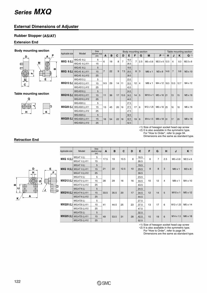
External Dimensions of Adjuster
Extension End
Applicable size
MXQ 6 (L)
MXQ 8 (L)
MXQ12 (L)
MXQ16 (L)
MXQ20 (L)
MXQ25 (L)
Model
MXQ-AS 6 (L)
MXQ-AS 6 (L)-X11
MXQ-AS 8 (L)
MXQ-AS 8( L)-X11
MXQ-AS 8 (L)-X12
MXQ-AS12 (L)
MXQ-AS12 (L)-X11
MXQ-AS12 (L)-X12
MXQ-AS16 (L)
MXQ-AS16 (L)-X11
MXQ-AS16 (L)-X12
MXQ-AS20 (L)
MXQ-AS20 (L)-X11
MXQ-AS20 (L)-X12
MXQ-AS25 (L)
MXQ-AS25 (L)-X11
MXQ-AS25 (L)-X12
5
15
5
15
25
5
15
25
5
15
25
5
15
25
5
15
25
Strokeadjustment range
(mm)
Body mounting section Table mounting section
A
6
7
9.5
11
13
16
Retraction End
Applicable size
MXQ 6 (L)
MXQ 8 (L)
MXQ12 (L)
MXQ16 (L)
MXQ20 (L)
MXQ25 (L)
Model
MXQ-AT 6 (L)
MXQ-AT 6 (L)-X11
MXQ-AT 8 (L)
MXQ-AT 8 (L)-X11
MXQ-AT 8 (L)-X12
MXQ-AT12 (L)
MXQ-AT12 (L)-X11
MXQ-AT12 (L)-X12
MXQ-AT16 (L)
MXQ-AT16 (L)-X11
MXQ-AT16 (L)-X12
MXQ-AT20 (L)
MXQ-AT20 (L)-X11
MXQ-AT20 (L)-X12
5
15
5
15
25
5
15
25
5
15
25
5
15
25
5
15
25
Strokeadjustment range
(mm)
B C F G M
M5 x 0.8
M6 x 1
M8 x 1
M10 x 1
M12 x 1.25
M14 x 1.5
P ∗1)
M2.5 x 6
M3 x 8
M4 x 12
M5 x 16
M6 x 16
M8 x 18
H J K Q ∗1)
M2.5 x 8
M3 x 10
M4 x 12
M5 x 16
M6 x 16
M8 x 18
16.5
26.5
19.5
29.5
39.5
23.5
33.5
43.5
24.5
34.5
44.5
27.5
37.5
47.5
32.5
42.5
52.5
D
A
17.5
21
28
33.5
41
49
B C F G H J K ∗1) ED
M5 x 0.8
M6 x 1
M8 x 1
M10 x 1
M12 x 1.25
M14 x 1.5
M2.5 x 6
M3 x 8
M4 x 10
M5 x 12
M5 x 14
M6 x 18
E
19
22
29
36
45
54
8
9
14
17
20
22
7
7.5
11
13.5
16
18
7
8
12
14
17
19
2.5
3
4
5
6
6
12.5
14.6
18.5
21
25
31
6
7
10.5
13
16
17
8.3
9.8
12.7
15
18
20
MXQ-AT25 (L)
MXQ-AT25 (L)-X11
MXQ-AT25 (L)-X12
19
22
29
35.5
44.5
53.5
10.5
12.5
16
20
25
31
8
10
16
17
23
28
16.5
26.5
19.5
29.5
39.5
23.5
33.5
43.5
24.5
34.5
44.5
27.5
37.5
47.5
32.5
42.5
52.5
6
8
10
12
13
15
7
8
12
14
17
19
2.5
3
4
5
6
6
H
J
Q
K
AB
E
P
M
G
D
F
C
E
J
F
B
C
D
H
G
AK
Rubber Stopper (AS/AT)
Body mounting section
Table mounting section
∗1) Size of hexagon socket head cap screw∗2) It is also available in the symmetric type.
For “How to Order”, refer to page 94. Dimensions are the same as standard type.
∗1) Size of hexagon socket head cap screw∗2) It is also available in the symmetric type.
For “How to Order”, refer to page 94. Dimensions are the same as standard type.
122
Series MXQ
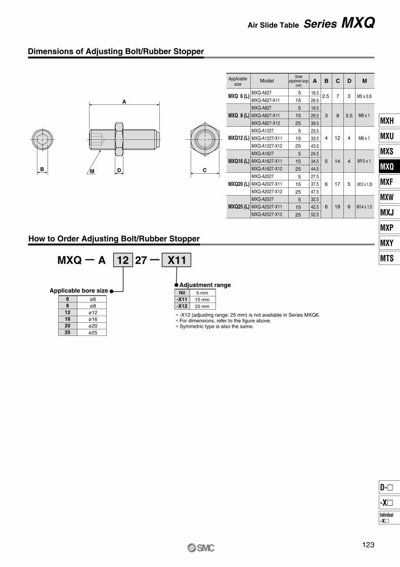
Dimensions of Adjusting Bolt/Rubber Stopper
MXQ
5 mm
15 mm
25 mm
6
8
12
16
20
25
ø6
ø8
ø12
ø16
ø20
ø25
12 X11
How to Order Adjusting Bolt/Rubber Stopper
Applicablesize
MXQ 6 (L)
MXQ 8 (L)
MXQ12 (L)
MXQ16 (L)
MXQ20 (L)
MXQ25 (L)
Model
MXQ-A627
MXQ-A627-X11
MXQ-A827
MXQ-A827-X11
MXQ-A827-X12
MXQ-A1227
MXQ-A1227-X11
MXQ-A1227-X12
MXQ-A1627
MXQ-A1627-X11
MXQ-A1627-X12
MXQ-A2027
MXQ-A2027-X11
MXQ-A2027-X12
MXQ-A2527
MXQ-A2527-X11
MXQ-A2527-X12
5
15
5
15
25
5
15
25
5
15
25
5
15
25
5
15
25
Strokeadjustment range
(mm)A B
2.5
3
4
5
6
6
C
716.5
26.5
19.5
29.5
39.5
23.5
33.5
43.5
24.5
34.5
44.5
27.5
37.5
47.5
32.5
42.5
52.5
8
12
14
17
19
MD
3
3.5
4
4
5
6
M5 x 0.8
M6 x 1
M8 x 1
M10 x 1
M12 x 1.25
M14 x 1.5
A 27
B D C
A
M
Applicable bore sizeAdjustment range
Nil
-X11
-X12
∗ -X12 (adjusting range: 25 mm) is not available in Series MXQ6.∗ For dimensions, refer to the figure above. ∗ Symmetric type is also the same.
123
Air Slide Table Series MXQ
MXH
MXU
MXS
MXQ
MXF
MXW
MXJ
MXP
MXY
MTS
Individual
-X�
D-�
-X�

Extension End
Applicable size
MXQ 8 (L)
MXQ12 (L)
MXQ16 (L)
MXQ20 (L)
MXQ25 (L)
Model
MXQ-BS 8 (L)
MXQ-BS12 (L)
MXQ-BS16 (L)
MXQ-BS20 (L)
MXQ-BS25 (L)
Body mounting section Table mounting section
A
Retraction End
MXQ 8 (L)
MXQ12 (L)
MXQ16 (L)
MXQ20 (L)
MXQ25 (L)
Model
MXQ-BT 8 (L)
MXQ-BT12 (L)
MXQ-BT16 (L)
MXQ-BT20 (L)
MXQ-BT25 (L)
20
18
22
35
35
B C F G M
M8 x 1
M8 x 1
M10 x 1
M14 x 1.5
M14 x 1.5
P *1)
M3 x 12
M4 x 12
M5 x 16
M6 x 18
M8 x 18
H J K Q ∗1)
M3 x 12
M4 x 12
M5 x 16
M6 x 20
M8 x 20
D
A B C E1 G H J K ∗1) ED
M8 x 1
M8 x 1
M10 x 1
M14 x 1.5
M14 x 1.5
Body mounting section Table mounting section
E
23
28
33.5
43
49
24.5
29
35.5
46
53.5
12.5
16
20
26
31
14
16
17
25
28
40.8
40.8
46.7
67.3
67.3
5
6
7
11
12
F
8
10
12
13
15
12
12
14
19
19
1.4
1.4
1.4
12
12
M3 x 8
M4 x 10
M5 x 12
M5 x 14
M6 x 18
20
18
22
35
35
7
9.5
11
13
16
24.5
29
36
46
54
14
14
17
22
22
12.5
11
13.5
17.5
18
LE1
40.8
40.8
46.7
67.3
67.3
5
6
7
11
12
12
12
14
19
19
1.4
1.4
1.4
12
12
16.6
20.5
23
27
33
8
11
13.5
17
19
12
13
16
22
22
14.6
18.5
21
25
31
MXQ-BT20 (L)MXQ-BT25 (L)
H
MXQ-BT 8 (L)MXQ-BT12 (L)MXQ-BT16 (L)
MXQ-BS 8 (L)MXQ-BS12 (L)MXQ-BS16 (L)
MXQ-BS20 (L)MXQ-BS25 (L)
G
D
F
C
G
P
M
E E1
B
A
Q
J
H
L
K
J
E
F
E1D
AK
H
B
C
G
External Dimensions of Adjuster
With Shock Absorber (BS/BT)
Strokeadjustment range
(mm)
∗1) Size of hexagon socket head cap screw∗2) It is also available in the symmetric type.
For “How to Order”, refer to page 94.Dimensions are the same as standard type.
Applicable size
Strokeadjustment range
(mm)
∗1) Size of hexagon socket head cap screw∗2) It is also available in the symmetric type.
For “How to Order”, refer to page 94.Dimensions are the same as standard type.
124
Series MXQ
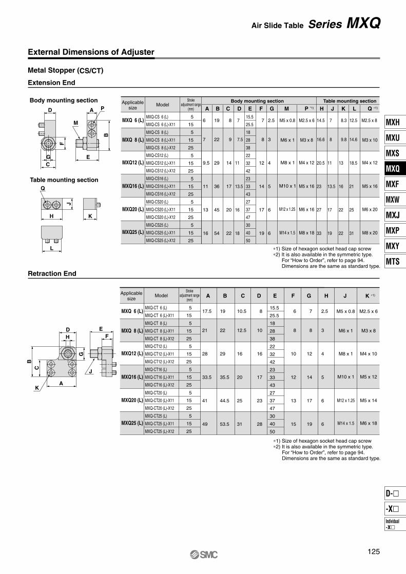
External Dimensions of Adjuster
Extension End
MXQ 6 (L)
MXQ 8 (L)
MXQ12 (L)
MXQ16 (L)
MXQ20 (L)
MXQ25 (L)
MXQ-CS 6 (L)
MXQ-CS 6 (L)-X11
MXQ-CS 8 (L)
MXQ-CS 8 (L)-X11
MXQ-CS 8 (L)-X12
MXQ-CS12 (L)
MXQ-CS12 (L)-X11
MXQ-CS12 (L)-X12
MXQ-CS16 (L)
MXQ-CS16 (L)-X11
MXQ-CS16 (L)-X12
MXQ-CS20 (L)
MXQ-CS20 (L)-X11
MXQ-CS20 (L)-X12
MXQ-CS25 (L)
MXQ-CS25 (L)-X11
MXQ-CS25 (L)-X12
5
15
5
15
25
5
15
25
5
15
25
5
15
25
5
15
25
Body mounting section Table mounting section
A
6
7
9.5
11
13
16
Retraction End
MXQ 6 (L)
MXQ 8 (L)
MXQ12 (L)
MXQ16 (L)
MXQ20 (L)
MXQ25 (L)
MXQ-CT 6 (L)
MXQ-CT 6 (L)-X11
MXQ-CT 8 (L)
MXQ-CT 8 (L)-X11
MXQ-CT 8 (L)-X12
MXQ-CT12 (L)
MXQ-CT12 (L)-X11
MXQ-CT12 (L)-X12
MXQ-CT16 (L)
MXQ-CT16 (L)-X11
MXQ-CT16 (L)-X12
MXQ-CT20 (L)
MXQ-CT20 (L)-X11
MXQ-CT20 (L)-X12
5
15
5
15
25
5
15
25
5
15
25
5
15
25
5
15
25
B C F G M
M5 x 0.8
M6 x 1
M8 x 1
M10 x 1
M12 x 1.25
M14 x 1.5
M2.5 x 6
M3 x 8
M4 x 12
M5 x 16
M6 x 16
M8 x 18
H J K
M2.5 x 8
M3 x 10
M4 x 12
M5 x 16
M6 x 20
M8 x 20
15.5
25.5
18
28
38
22
32
42
23
33
43
27
37
47
30
40
50
D
A
17.5
21
28
33.5
41
49
B C F G H JED
M5 x 0.8
M6 x 1
M8 x 1
M10 x 1
M12 x 1.25
M14 x 1.5
M2.5 x 6
M3 x 8
M4 x 10
M5 x 12
M5 x 14
M6 x 18
E
19
22
29
36
45
54
8
9
14
17
20
22
7
7.5
11
13.5
16
18
7
8
12
14
17
19
2.5
3
4
5
6
6
14.5
16.6
20.5
23
27
33
7
8
11
13.5
17
19
8.3
9.8
13
16
22
22
MXQ-CT25 (L)
MXQ-CT25 (L)-X11
MXQ-CT25 (L)-X12
19
22
29
35.5
44.5
53.5
10.5
12.5
16
20
25
31
8
10
16
17
23
28
15.5
25.5
18
28
38
22
32
42
23
33
43
27
37
47
30
40
50
6
8
10
12
13
15
7
8
12
14
17
19
2.5
3
4
5
6
6
L
12.5
14.6
18.5
21
25
31
AB
E
P
M
G
D
F
C
E
J
F
B
C
D
H
G
AK
Q
J
H
L
K
Metal Stopper (CS/CT)
Body mounting section
Table mounting section
Applicablesize
ModelStroke
adjustment range(mm) P *1) Q ∗1)
∗1) Size of hexagon socket head cap screw∗2) It is also available in the symmetric type.
For “How to Order”, refer to page 94. Dimensions are the same as standard type.
Applicablesize
ModelStroke
adjustment range(mm)
K ∗1)
∗1) Size of hexagon socket head cap screw∗2) It is also available in the symmetric type.
For “How to Order”, refer to page 94. Dimensions are the same as standard type.
125
Air Slide Table Series MXQ
MXH
MXU
MXS
MXQ
MXF
MXW
MXJ
MXP
MXY
MTS
Individual
-X�
D-�
-X�

Dimensions of Adjusting Bolt/Metal Stopper
MXQ
5 mm
15 mm
25 mm
MXQ 6
MXQ 8
MXQ12
MXQ16
MXQ20
MXQ25
ø6
ø8
ø12
ø16
ø20
ø25
12 X11
MXQ 6 (L)
MXQ 8 (L)
MXQ12 (L)
MXQ16 (L)
MXQ20 (L)
MXQ25 (L)
MXQ-A638
MXQ-A638-X11
MXQ-A838
MXQ-A838-X11
MXQ-A838-X12
MXQ-A1238
MXQ-A1238-X11
MXQ-A1238-X12
MXQ-A1638
MXQ-A1638-X11
MXQ-A1638-X12
MXQ-A2038
MXQ-A2038-X11
MXQ-A2038-X12
MXQ-A2538
MXQ-A2538-X11
MXQ-A2538-X12
5
15
5
15
25
5
15
25
5
15
25
5
15
25
5
15
25
A B
2.5
3
4
5
6
6
C
715.5
25.5
18
28
38
22
32
42
23
33
43
27
37
47
30
40
50
8
12
14
17
19
MD
3
3.5
4
4
5
6
M5 x 0.8
M6 x 1
M8 x 1
M10 x 1
M12 x 1.25
M14 x 1.5
A 38
C
A
DMB
How to Order Adjusting Bolt/Metal Stopper
Applicablesize
ModelStroke
adjustment range(mm)
Applicable bore sizeAdjustment rangeNil
-X11
-X12
∗ -X12 (adjusting range: 25 mm) is not available in Series MXQ6.
∗ For dimensions, refer to the figure above.
∗ Symmetric type is also the same.
126
Series MXQ

Construction
No.
1
2
3
4
5
6
Description
Body
Table
End plate
Guide block
Cover
Return guide
Scraper
Rod
Piston assembly
Rod cover
Seal support
Head cap
Floating bushing
Rod bumper
End bumper
Steel balls
Parallel pin
Piston seal
Rod seal
O-ring
7
8
9
10
11
12
13
14
15
16
17
18
19
20
Aluminum alloy
Stainless steel
Aluminum alloy
Stainless steel
Synthetic resin
Synthetic resin
Stainless steel, NBR
Stainless steel
—
Aluminum alloy
Brass
Synthetic resin
Stainless steel
Polyurethane
Polyurethane
High carbon chrome bearing steel
Stainless steel
NBR
NBR
NBR
Material
Hard anodized
Heat treated, Electroless nickel plated
Hard anodized
Heat treated
With magnet on one side
Anodized
Electroless nickel plated
Note
Component Parts
No.
21
22
23
24
25
Description
End plate
Spring collar
Head cap
Spring
Magnet
Aluminum alloy
Stainless steel
Stainless steel
Stainless steel
—
Material Note
Hard anodized
Component Parts: With Buffer
Replacement Parts: Seal Kit
68
12162025
Bore size (mm)
No.
26
27
28
29
30
31
32
33
34
35
36
Description
Locking body
Table support
Rod cover
Piston rod
Bushing
Blanking plug
Return spring
Piston seal
Rod seal
O-ring
O-ring
Aluminum alloy
Carbon steel
Aluminum alloy
Stainless steel
Aluminum alloy
Brass
Stainless steel
NBR
NBR
NBR
NBR
Material
Hard anodized
Anti-corrosive treated
Chromated
Electroless nickel plated
Note
Component Parts: With End Lock
No.
37
38
39
40
41
42
43
44
Description
Axial piping plate
Pipe
Bushing
Stud
O-ring
O-ring
Gasket
O-ring
Aluminum alloy
Aluminum alloy
Aluminum alloy
Brass
NBR
NBR
NBR, Stainless steel
NBR
Material
Hard anodized
Hard anodized
Chromated
Electroless nickel plated
Note
Component Parts: Axial Piping Type
Kit no.
MXQ 6-PS
MXQ 8-PS
MXQ12-PS
MXQ16-PS
MXQ20-PS
MXQ25-PS
Contents
68
12162025
MXQ 6P-PS
MXQ 8P-PS
MXQ12P-PS
MXQ16P-PS
MXQ20P-PS
MXQ25P-PS
812162025
MXQ 8R-PS
MXQ12R-PS
MXQ16R-PS
MXQ20R-PS
MXQ25R-PS
Grease packpart no.
GR-S-005 (5g)GR-S-010 (10g)GR-S-020 (20g)GR-S-050 (50g)
GR-L-005 (5g)GR-L-010 (10g)GR-L-020 (20g)GR-L-050 (50g)
Appliedsection
Guide
Cylinder
With buffer With end lock Axial piping type
Replacement Parts: Seal Kit for with End Lock
Bore size (mm) Kit no. Contents
Bore size (mm) Kit no. Contents
Replacement Parts:Seal Kit for Axial Piping Type
Replacement Parts:Grease Pack
∗ Seal kit includes these seals to provide as a set. Order the seal kit, based on each bore size.
127
Air Slide Table Series MXQ
MXH
MXU
MXS
MXQ
MXF
MXW
MXJ
MXP
MXY
MTS
Individual
-X�
D-�
-X�

Auto Switch Proper Mounting Position (Detection at Stroke End)
MXQ6
MXQ8
MXQ12
MXQ16
MXQ20
MXQ25
6
7.5
11.5
16.5
19
22
Reed Auto Switch: D-A90, D-A93, D-A96, D-A90V, D-A93V, D-A96V
10
5.5
8
24.5
30.5
43.5
52.5
20
5.5
8
14.5
20.5
33.5
42.5
30
5.5
12
14.5
20.5
23.5
32.5
125
—
—
—
51.5
74.5
88.5
75
—
32
40.5
33.5
39.5
46.5
100
—
—
40.5
51.5
71.5
60.5
Stroke
B
Stroke
E
Model A
40
13.5
16
21.5
20.5
33.5
32.5
50
13.5
31
21.5
26.5
31.5
46.5
150
—
—
—
—
77.5
88.5
10
20 30 125
—
—
—
75
—
100
—
—
40 50 150
—
—
—
—
MXQ6
MXQ8
MXQ12
MXQ16
MXQ20
MXQ25
10
11.5
15.5
20.5
23
27
Solid State Auto Switch: D-M9B, D-M9N, D-M9P, D-M9BW, D-M9NW, D-M9PW
10
9.5
12
28.5
34.5
47.5
56.5
20
9.5
12
18.5
24.5
37.5
46.5
30
9.5
16
18.5
24.5
27.5
36.5
125
—
—
—
55.5
78.5
92.5
75
—
36
44.5
37.5
43.5
50.5
100
—
—
44.5
55.5
75.5
64.5
Stroke
B
Stroke
E
Model A
40
17.5
20
25.5
24.5
37.5
36.5
50
17.5
35
25.5
30.5
35.5
50.5
150
—
—
—
—
81.5
92.5
10 20 30 12575
—
10040 50 150
Solid State Auto Switch: D-M9BV, D-M9NV, D-M9PV, D-M9BWV, D-M9NWV, D-M9PWV
–0.5
3.5(1)6
(3.5)22.5(20)28.5(26)41.5(39)50.5(48)
3.5(1)6
(3.5)12.5(10)18.5(16)31.5(29)40.5(38)
3.5(1)10
(7.5)12.5(10)18.5(16)21.5(19)30.5(28)
11.5(9)14
(11.5)19.5(17)18.5(16)31.5(29)30.5(28)
11.5(9)29
(26.5)19.5(17)24.5(22)29.5(27)44.5(42)
30(27.5)38.5(36)31.5(29)37.5(35)44.5(42)
38.5(36)49.5(47)69.5(67)58.5(56)
49.5(47)72.5(70)86.5(84)
77.5(75)77.5(75)
–0.5 –0.5 7.5 7.5
2 2 6 10 25
18.5 8.5 8.5 15.5 15.5
24.5 14.5 14.5 14.5 20.5
37.5 27.5 17.5 27.5 25.5
46.5 36.5 26.5 26.5 40.5
26
34.5 34.5
27.5 45.5 45.5
33.5 65.5 68.5 73.5
40.5 54.5 82.5 73.5
A E
B
Caution
MXQ6
MXQ8
MXQ12
MXQ16
MXQ20
MXQ25
10
11.5
15.5
20.5
23
27
10
9.5
12
28.5
34.5
47.5
56.5
20
9.5
12
18.5
24.5
37.5
46.5
30
9.5
16
18.5
24.5
27.5
36.5
125
55.5
78.5
92.5
75
36
44.5
37.5
43.5
50.5
100
44.5
55.5
75.5
64.5
Stroke
B
Stroke
E
Model A
40
17.5
20
25.5
24.5
37.5
36.5
50
17.5
35
25.5
30.5
35.5
50.5
150
81.5
92.5
10
1.5
4
20.5
26.5
39.5
48.5
20
1.5
4
10.5
16.5
29.5
38.5
30
1.5
8
10.5
16.5
19.5
28.5
125
47.5
70.5
84.5
75
28
36.5
29.5
35.5
42.5
100
36.5
47.5
67.5
56.5
40
9.5
12
17.5
16.5
29.5
28.5
50
9.5
27
17.5
22.5
27.5
42.5
150
75.5
75.5
Auto Switch Mounting Operating Range
D-A9, A9�V
D-M9�, M9�V
D-M9�W, M9�WV
Operating range
6
4.5
2.5
8
5
2.5
12
6
3
16
7
4
20
8
4.5
25
9
5
Auto switch model
Tightening Torque of Auto Switch Mounting Screw
Auto switch model Tightening torque
0.10 to 0.20
0.05 to 0.15
D-A9�(V)
D-M9�(V)D-M9�W(V)
(N•m)
Auto Switch Mounting Tool• When tightening the auto switch mounting screw (included with
auto switch), use a watchmaker’s screwdriver with a handle about
5 to 6 mm in diameter.
Tightening Torque
∗ ( ): Denotes D-A93.
— — — —
— — —
— —
—
— — — —
— — —
— —
—
Note) Adjust the auto switch after confirming the operating conditions in the actual setting.
∗ Since the operating range is provided as a guideline including hysteresis, it cannot be guaranteed (assuming approximately ±30% dispersion). It may vary substantially depending on an ambient environment.
Auto switch
Watchmaker’s screwdriver
Auto switch mounting screw
(included with auto switch)
Other than the applicable auto switches listed in “How to Order”, the following auto switches can be mounted.
∗ Normally closed (NC = b contact) solid state auto switches (D-F9G/F9H types) and solid state auto switch D-F8 are also available.
Refer to pages 1745 and 1746 for details.
—
—
—
—
—
—
—
—
—
Applicable bore size
(mm)
128
Series MXQ

MountingSelection
Caution
Model
MXQ 6 (L)
MXQ 8 (L)
MXQ12 (L)
MXQ16 (L)
MXQ20 (L)
MXQ25 (L)
Bolt
M4 x 0.7
M4 x 0.7
M5 x 0.8
M6 x 1
M6 x 1
M8 x 1.25
2.1
2.1
4.4
7.4
7.4
18.0
8
8
10
12
12
16
1. Lateral Mounting (Body tapped)
Model
MXQ 6 (L)
MXQ 8 (L)
MXQ12 (L)
MXQ16 (L)
MXQ20 (L)
MXQ25 (L)
Bolt
M3 x 0.5
M3 x 0.5
M4 x 0.7
M5 x 0.8
M5 x 0.8
M6 x 1
1.2
1.2
2.8
5.7
5.7
10.0
10.5
12.5
16
21
26
32
2. Lateral Mounting (Body through-hole)
Model
MXQ 6 (L)
MXQ 8 (L)
MXQ12 (L)
MXQ16 (L)
MXQ20 (L)
MXQ25 (L)
Bolt
M2.5 x 0.45
M3 x 0.5
M4 x 0.7
M5 x 0.8
M5 x 0.8
M6 x 1
0.5
0.9
2.1
4.4
4.4
7.4
4
4
6
7
8
10
3. Vertical Mounting (Body tapped)
ll
Caution
l
Mounting
1. Operate loads within the range
of the operating limits.Select the model considering maximum allowable load and allowable moment. Refer to pages 90 and 91 for the details. When actuator is used outside of operating limits, eccentric loads on guide will be in excess of this causing vibration on guide, inaccuracy, and shortened life.
2. If intermediate stops by external
stopper is done, avoid ejection.If lurching occurs damage can result. When making a stop with an external stopper to be followed by continued forward movement, first supply pressure to momentarily reverse the table, then retract the intermediate stopper, and finally apply pressure to the opposite port to operate the table again.
3. Do not use it in such a way that
excessive external force or
impact force could work on it.This could result in damage.
1. Do not scratch or dent the
mounting side of the body, table
or end plate.This can cause loss of parallelism in the mounting surfaces, vibration in the guide unit and increased operating resistance, etc.
2. Do not scratch or dent on the
forward side of the rail or guide.This could result in looseness and increased operating resistance, etc.
3. Do not apply excessive power
and load when work is mounted.If the external force more than the allowable moment were applied, looseness of the guide unit or increased operating resistance could take place.
4. Flatness of mounting surface
should be less than 0.02 mm.Poor parallelism of the workpiece mounted on the body, the base, and other parts can cause vibration in the guide unit and increased operating resistance, etc.
5. Select the proper connection
with the load which has external
support and/or guide mechanism
on the outside, and align it
properly.
6. Avoid contact with the body
during operation.Hands, etc., may get caught in the stroke adjuster. Install a cover as a safety measure if there are instances to be near the slide table during operation.
7. Keep away from objects which
are influenced by magnets.As the body magnets are built-in, do not allow close contact with magnetic disks, magnetic cards or magnetic tapes. Data may be erased.
8. Do not touch a magnet to the
table section.Since the table is made from the magnetic substance, it could turn to be magnetized if it stuck by a magnet, etc. That could cause auto switches, etc. to malfunction.
9. When mounting the body, use
screws with appropriate length
and do not exceed the maximum
tightening torque.Tightening with a torque above the limit could malfunction. Whereas tightening insufficiently could result in misalignment or come to a drop.
Maximum tighteningtorque (N·m)
Maximum screw-in depth (l mm)
Maximum tighteningtorque (N·m)
Maximum screw-in depth (l mm)
129
Series MXQSpecific Product Precautions 1Be sure to read before handling. Refer to front matters 42 and 43 for Safety Instructions and pages 3 to 11 for Actuator and Auto Switch Precautions.
l mmMaximum tighteningtorque (N·m)
MXH
MXU
MXS
MXQ
MXF
MXW
MXJ
MXP
MXY
MTS
Individual
-X�
D-�
-X�
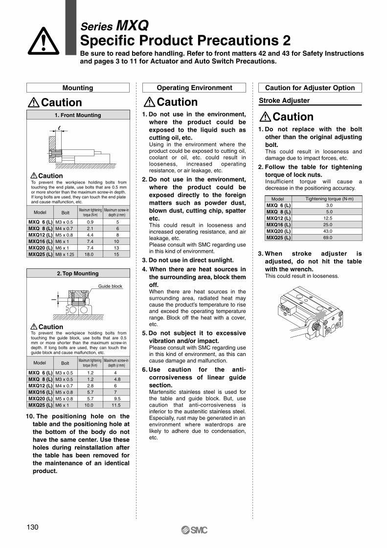
Mounting Operating Environment
CautionCaution
MXQ 6 (L)
MXQ 8 (L)
MXQ12 (L)
MXQ16 (L)
MXQ20 (L)
MXQ25 (L)
M3 x 0.5
M4 x 0.7
M5 x 0.8
M6 x 1
M6 x 1
M8 x 1.25
0.9
2.1
4.4
7.4
7.4
18.0
5
6
8
10
13
15
1. Front Mounting
MXQ 6 (L)
MXQ 8 (L)
MXQ12 (L)
MXQ16 (L)
MXQ20 (L)
MXQ25 (L)
M3 x 0.5
M3 x 0.5
M4 x 0.7
M5 x 0.8
M5 x 0.8
M6 x 1
1.2
1.2
2.8
5.7
5.7
10.0
4
4.8
6
7
9.5
11.5
2. Top Mounting
Model
MXQ 6 (L)
MXQ 8 (L)
MXQ12 (L)
MXQ16 (L)
MXQ20 (L)
MXQ25 (L)
Tightening torque (N·m)
3.0
5.0
12.5
25.0
43.0
69.0
Caution for Adjuster Option
Caution
Stroke Adjuster
l
l
Caution
Series MXQSpecific Product Precautions 2Be sure to read before handling. Refer to front matters 42 and 43 for Safety Instructions and pages 3 to 11 for Actuator and Auto Switch Precautions.
To prevent the workpiece holding bolts from touching the end plate, use bolts that are 0.5 mm or more shorter than the maximum screw-in depth. If long bolts are used, they can touch the end plate and cause malfunction, etc.
Model BoltMaximum tightening
torque (N·m)Maximum screw-in
depth (l mm)
Guide block
To prevent the workpiece holding bolts from touching the guide block, use bolts that are 0.5 mm or more shorter than the maximum screw-in depth. If long bolts are used, they can touch the guide block and cause malfunction, etc.
Caution
Model BoltMaximum tightening
torque (N·m)Maximum screw-in
depth (l mm)
10. The positioning hole on the
table and the positioning hole at
the bottom of the body do not
have the same center. Use these
holes during reinstallation after
the table has been removed for
the maintenance of an identical
product.
1. Do not use in the environment,
where the product could be
exposed to the liquid such as
cutting oil, etc.Using in the environment where the product could be exposed to cutting oil, coolant or oil, etc. could result in looseness, increased operating resistance, or air leakage, etc.
2. Do not use in the environment,
where the product could be
exposed directly to the foreign
matters such as powder dust,
blown dust, cutting chip, spatter
etc.This could result in looseness and increased operating resistance, and air leakage, etc.Please consult with SMC regarding use in this kind of environment.
3. Do not use in direct sunlight.
4. When there are heat sources in
the surrounding area, block them
off.When there are heat sources in the surrounding area, radiated heat may cause the product’s temperature to rise and exceed the operating temperature range. Block off the heat with a cover, etc.
5. Do not subject it to excessive
vibration and/or impact.Please consult with SMC regarding use in this kind of environment, as this can cause damage and malfunction.
6. Use caution for the anti-
corrosiveness of linear guide
section.Martensitic stainless steel is used for the table and guide block. But, use caution that anti-corrosiveness is inferior to the austenitic stainless steel. Especially, rust may be generated in an environment where waterdrops are likely to adhere due to condensation, etc.
1. Do not replace with the bolt
other than the original adjusting
bolt.This could result in looseness and damage due to impact forces, etc.
2. Follow the table for tightening
torque of lock nuts.Insufficient torque will cause a decrease in the positioning accuracy.
3. When stroke adjuster is
adjusted, do not hit the table
with the wrench.This could result in looseness.
130

Caution
Rubber Stopper
Caution on Mounting Adjuster Option
Caution
Shock Absorber
Model
MXQ 6 (L)MXQ 8 (L)MXQ12 (L)MXQ16 (L)MXQ20 (L)MXQ25 (L)
0.5
0.9
2.1
4.4
7.0
18.0
M2.5 x 6
M3 x 8
M4 x 12
M5 x 16
M6 x 16
M8 x 18
M2.5 x 8
M3 x 10
M4 x 12
M5 x 16
M6 x 16
M8 x 18
Stroke adjuster at extension end (AS) Stroke adjuster at
retraction end (AT)Body mounting section Table mounting section
M2.5 x 6
M3 x 8
M4 x 10
M5 x 12
M5 x 14
M6 x 18
Thread size Tightening torque (N·m) Thread size Tightening torque (N·m) Thread size Tightening torque (N·m)
0.5
0.9
2.1
4.4
7.0
18.0
0.5
0.9
2.1
4.4
4.4
7.0
Model
MXQ 6 (L)MXQ 8 (L)MXQ12 (L)MXQ16 (L)MXQ20 (L)MXQ25 (L)
0.5
0.9
2.1
4.4
7.0
18.0
M2.5 x 6
M3 x 8
M4 x 12
M5 x 16
M6 x 16
M8 x 18
M2.5 x 8
M3 x 10
M4 x 12
M5 x 16
M6 x 20
M8 x 20
Stroke adjuster at extension end (CS) Stroke adjuster at
retraction end (CT)Body mounting section Table mounting section
M2.5 x 6
M3 x 8
M4 x 10
M5 x 12
M5 x 14
M6 x 18
0.5
0.9
2.1
4.4
7.0
18.0
0.5
0.9
2.1
4.4
4.4
7.0
Model
MXQ 8 (L)MXQ12 (L)MXQ16 (L)MXQ20 (L)MXQ25 (L)
0.9
2.1
4.4
7.0
18.0
M3 x 12
M4 x 12
M5 x 16
M6 x 18
M8 x 18
M3 x 12
M4 x 12
M5 x 16
M6 x 20
M8 x 20
Shock absorber at extension end (BS) Shock absorber at
retraction end (BT)Body mounting section Table mounting section
M3 x 8
M4 x 10
M5 x 12
M5 x 14
M6 x 18
0.9
2.1
4.4
7.0
18.0
0.9
2.1
4.4
4.4
7.0
Caution
Metal Stopper
Caution
With Shock Absorber
Caution on Adjuster Option
Applicable size
MXQ 8 (L)MXQ12 (L)
Tightening torque (N•m)
1.67
3.14
10.8MXQ20 (L)MXQ25 (L)
MXQ16 (L)
Applicable size
MXQ 8 (L)
MXQ12 (L)
MXQ16 (L)
MXQ20 (L)
MXQ25 (L)
Shock absorber model
RB0805
RB0806
RB1007
RB1411
RB1412
1. Allowable operating cycle under
the specifications set in this
catalog is shown below.
1.2 million cycles RB08��
2 million cycles RB10�� to RB14��
Note) Specified service life (suitable replacement
period) is the value at room temperature
(20 to 25°C). The period may vary
depending on the temperature and other
conditions. In some cases the absorber
may need to be replaced before the
allowable operating cycle above.
Caution
Service Life and ReplacementPeriod of Shock Absorber
1. Do not rotate the screw set on
bottom of shock absorber.This is not an adjusting screw. Turning it
could cause oil leakage.
2. Do not scratch the exposed
portion of the piston rod.Durability could be degraded and lead to
return defect.
Turning thebottom screw is not allowed.Piston rod
Damage is not allowed.
3. Shock absorber is considered a
consumable component. When
energy absorption is decreased,
replace it.
1. Use caution that the length of the bolts for mounting on the body and
the bolts for the table is different from each other in some models. Stroke adjuster at extension end (AS) of MXQ6 and 8 has the different length of a hexagon socket
head cap screw for mounting on the body and on the table. Use sufficient care for mounting.
If assembled by making an error in length, it could cause looseness or lead to malfunction.
2. Follow the table below for tightening torque of mounting bolts.Insufficient torque will cause a decrease in the positioning accuracy and lead to malfunction.
1. Use caution that the length of the bolts for mounting on the body and
the bolts for the table is different from each other in some models. Shock absorber at extension end (BS) for MXQ20 and 25 has the different length of a hexagon
socket head cap screw for mounting on the body and on the table. Use sufficient care for
mounting.
If assembled by making an error in length, it could cause looseness or lead to malfunction.
2. Follow the table below for tightening torque of mounting bolts.Insufficient torque will cause a decrease in the positioning accuracy and lead to malfunction.
Thread size Tightening torque (N·m) Thread size Tightening torque (N·m) Thread size Tightening torque (N·m)
1. Use caution that the length of the bolts for mounting on the body and
the bolts for the table is different from each other in some models. Stroke adjuster at extension end (CS) of MXQ6, 8, 20 and 25 has the different length of a hexagon
socket head cap screw for mounting on the body and on the table. Use sufficient care for
mounting.
If assembled by making an error in length, it could cause looseness or lead to malfunction.
2. Follow the table below for tightening torque of mounting bolts.Insufficient torque will cause a decrease in the positioning accuracy and lead to malfunction.
Thread size Tightening torque (N·m) Thread size Tightening torque (N·m) Thread size Tightening torque (N·m)
131
Series MXQSpecific Product Precautions 3Be sure to read before handling. Refer to front matters 42 and 43 for Safety Instructions and pages 3 to 11 for Actuator and Auto Switch Precautions.
MXH
MXU
MXS
MXQ
MXF
MXW
MXJ
MXP
MXY
MTS
Individual
-X�
D-�
-X�
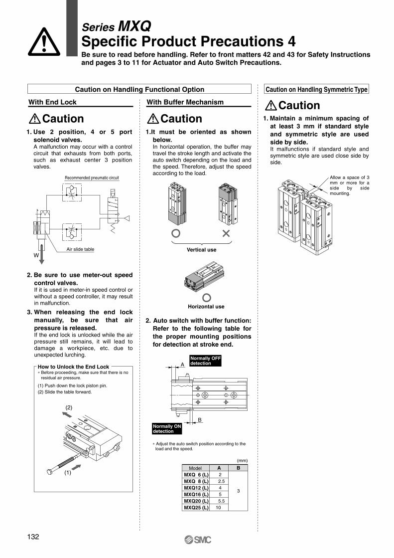
Caution
With End Lock
Caution on Handling Functional Option
How to Unlock the End Lock∗ Before proceeding, make sure that there is no
residual air pressure.
(1) Push down the lock piston pin.
(2) Slide the table forward.
Caution
With Buffer Mechanism
Model
MXQ 6 (L)
MXQ 8 (L)
MXQ12 (L)
MXQ16 (L)
MXQ20 (L)
MXQ25 (L)
A
2
2.5
4
5
5.5
10
B
3
W
Caution on Handling Symmetric Type
Caution
A
B
(2)
(1)
1. Use 2 position, 4 or 5 port
solenoid valves.A malfunction may occur with a control circuit that exhausts from both ports, such as exhaust center 3 position valves.
Recommended pneumatic circuit
Air slide table
2. Be sure to use meter-out speed
control valves.If it is used in meter-in speed control or without a speed controller, it may result in malfunction.
3. When releasing the end lock
manually, be sure that air
pressure is released.If the end lock is unlocked while the air pressure still remains, it will lead to damage a workpiece, etc. due to unexpected lurching.
1.It must be oriented as shown
below.In horizontal operation, the buffer may travel the stroke length and activate the auto switch depending on the load and the speed. Therefore, adjust the speed according to the load.
Vertical use
Horizontal use
2. Auto switch with buffer function:
Refer to the following table for
the proper mounting positions
for detection at stroke end.
Normally OFFdetection
Normally ONdetection
∗ Adjust the auto switch position according to theload and the speed.
(mm)
1. Maintain a minimum spacing of
at least 3 mm if standard style
and symmetric style are used
side by side.It malfunctions if standard style and symmetric style are used close side by side.
Allow a space of 3 mm or more for a side by side mounting.
132
Series MXQSpecific Product Precautions 4Be sure to read before handling. Refer to front matters 42 and 43 for Safety Instructions and pages 3 to 11 for Actuator and Auto Switch Precautions.

Series MXQHow to Order
Air slide tableø6, ø8, ø12, ø16, ø20, ø25
Auto switch specifications (Refer to Best Pneumatics catalog for detailed specifications and auto switches not in the following table.)
Specialfunction
—
—
Electricalentry
Grommet
Grommet
Indicatorlight
Yes
Yes
Type
Reed switch
Solid state switch
Wiring(Output)
2-wire
3-wire (NPN)
2-wire
12V
In-line
A93
M9N
M9B
—
—
—
�
�
�
�
�
�—
100V
12V
12V
24V
24V
Load voltage
ACDC
Lead wire length (m) ∗
0.5Nil
3(L)
Applicable load
∗ Lead wire length symbols: 0.5m………Nil (Example) A93 3 m………L (Example) A93L
PLC: Programmable Logic Controller
Auto switch modelElectrical entry direction
Relay, PLC
Relay, PLC
10, 20, 30, 40, 50
10, 20, 30, 40, 50, 75
10, 20, 30, 40, 50, 75, 100
10, 20, 30, 40, 50, 75, 100, 125
10, 20, 30, 40, 50, 75, 100, 125, 150
10, 20, 30, 40, 50, 75, 100, 125, 150
Adjuster option
Nil
S
n
Bore size / Stroke (mm)6
8
12
16
20
25
Number of auto switches2 pcs.
1 pc.
"n" pcs.
Nil
AS
AT
A
CS
CT
C
Extension endRetraction endBoth ends
Extension end
Retraction end
Both ends
Type of auto switchNil Without auto switch
∗ For the applicable auto switch model, refer to the table below.
Nil
PNote)
Functional option
Standard type
Axial piping type
Nil
L
Symmetric typeStandard type
Symmetric type
Without adjuster
Rubberstopper
Metalstopper
13-22-
MXQ 1222 50 M9N
MXQ 1213 50 M9N
Copper, fluorine and silicon-free +Low particle generation
22 Vacuum suction type
Clean series13 Vacuum suction type (Special treatment on guide)
Refer to page 182 for a list of applicable auto switches.
Symbol
Nil
TN
TF
Port thread typeThread type
M-thread
Rc
NPT
G
Bore size
ø6 to ø16
ø20, ø25
ø20, ø25
ø20, ø25
106
Note) The combination of axial piping type and both ends adjusters or retraction end adjuster is not available.

Proper auto switch mounting position (Detection at stroke end)
Adjuster Option: Stroke Adjustment Range
Rubber stopper
Metal stopper
Extension end (AS)
Retraction end (AT)
Both ends (A)
Extension end (CS)
Retraction end (CT)
Both ends (C)
Suction flow rate ofvacuum suction type(Reference values)
Bore size
6, 8, 12
16
20
25
Suction flow rate l/min (ANR)
1
2
3
5
Stroke adjustment range0 to 5 mm
Stroke adjustment range0 to 5 mm
13-/22-MXQ6(L)13-/22-MXQ8(L)13-/22-MXQ12(L)13-/22-MXQ16(L)13-/22-MXQ20(L)13-/22-MXQ25(L)
6
7.5
11.5
16.5
19
22
Reed switch: D-A93
10
5.5
8
24.5
30.5
43.5
52.5
20
5.5
8
14.5
20.5
33.5
42.5
30
5.5
12
14.5
20.5
23.5
32.5
125
—
—
—
51.5
74.5
88.5
75
—
32
40.5
33.5
39.5
46.5
100
—
—
40.5
51.5
71.5
60.5
4.5
5
6
7
8
9
Stroke
BStroke
E
Model A40
13.5
16
21.5
20.5
33.5
32.5
50
13.5
31
21.5
26.5
31.5
46.5
150
—
—
—
—
77.5
88.5
10
20 30 125
—
—
—
75
—
100
—
—
40 50 150
—
—
—
—
13-/22-MXQ6(L)
13-/22-MXQ8(L)
13-/22-MXQ12(L)
13-/22-MXQ16(L)
13-/22-MXQ20(L)
13-/22-MXQ25(L)
10
11.5
15.5
20.5
23
27
Solid state switch: D-M9B, D-M9N
10
9.5
12
28.5
34.5
47.5
56.5
20
9.5
12
18.5
24.5
37.5
46.5
30
9.5
16
18.5
24.5
27.5
36.5
125
—
—
—
55.5
78.5
92.5
75
—
36
44.5
37.5
43.5
50.5
100
—
—
44.5
55.5
75.5
64.5
1.5
1.5
2.5
3
3
3
Stroke
BStroke
E
Model A40
17.5
20
25.5
24.5
37.5
36.5
50
17.5
35
25.5
30.5
35.5
50.5
150
—
—
—
—
81.5
92.5
10 20 30 125
—
—
—
75
—
100
—
—
40 50 150
—
—
—
—
-0.5
1
3.5
20
26
39
48
1
3.5
10
16
29
38
1
7.5
10
16
19
28
9
11.5
17
16
29
28
9
26.5
17
22
27
42
27.5
36
29
35
42
36
47
67
56
47
70
84
75
75
-0.5 -0.5 7.5 7.5
2 2 6 10 25
18.5 8.5 8.5 15.5 15.5
24.5 14.5 14.5 14.5 20.5
37.5 27.5 17.5 27.5 25.5
46.5 36.5 26.5 26.5 40.5
26
34.5 34.5
27.5 45.5 45.5
33.5 65.5 68.5 73.5
40.5 54.5 82.5 73.5
EA B
MXQAir slide table 13-22-
Specifications
Bore size (mm)
Fluid
Action
Operating pressure
Proof pressure
Ambient and fluid temperature
Piston speed
Cushion
Lubrication
Stroke length tolerance
Grease
Without adjuster
Rubber stopper
Metal stopper
Particle generation grade (Refer to front matter pages 13 to 22 for details.)
6 8 12 16 20 25
Air
Double acting
0.15 to 0.7MPa
1.05 MPa
–10 to 60°C (No freezing)
50 to 300 mm/s(Adjuster option/Metal stopper: 50 to 200 mm/s)
Rubber bumper (Standard, Adjuster option/Rubber stopper)None (Adjuster option/Metal stopper)
Non-lube
mm
10-/11-: Fluorine grease21-/22-: Lithium soap based grease
13-/22-: Grade 3
13-/22-: Grade 4
+10
107
Auto switch operation range
Auto switch operation range
Air
cylin
der
Rot
ary
actu
ator
Air
grip
per
Dire
ctio
nal c
ontr
olva
lve
Fitt
ings
& T
ubin
gP
ress
ure
switc
hC
lean
gas
filte
rF
low
con
trol
equi
pmen
tF
ilter
, Pre
ssur
eco
ntro
l equ
ipm
ent
Air
prep
arat
ion
equi
pmen
t

Model
Note) Refer to the bottom view of 13-MXQ6-30.
F2225212627
N44666
G 613—1121
H2326—2828
NN22333
I 999
169
J1727374865
K21.531.541.551.561.5
Z41.551.561.579.589.5
M4252628090
ZZ647484
102112
13-/22-MXQ6-1013-/22-MXQ6-2013-/22-MXQ6-3013-/22-MXQ6-4013-/22-MXQ6-50
4-M2.5 x 0.45 thread depth 3.5
4-M2.5 x 0.45 thread depth 2.5
Section AA Section BB
Extension end adjuster
Retraction end adjuster
ø3 depth 2.5+0.03 0
2N –1 x F
3
de
pth
2.5
+0.0
3 0
ø3H9 depth 2.5+0.025 0
3H9
dep
th 2
.5+
0.02
5 0
(mm)
GA1313293949
HA1626202828
Z
ZZ
Max. 10 (Retraction end adjuster)6IJ
10.5 5.5
6 (E
xten
sion
end
adj
uste
r)
34
2 6
131620
3-M3 x 0.5 thread depth 5
Vacuum suction port M5 x 0.8
1
19.5 (Extension end adjuster)
5.5
7
3.5
2-M2.5 x 0.45 thread depth 3
Operating port 2-M5 x 0.8
5.5
10
20
13.5
4
9
4
N-M3 x 0.5 thread depth 4
14 271.
5
31
5.5 3
1512
19.2
0.3
F
27
21 M
12.5K
6.53
3.5
20
10.5 5.5
ø6.
5
ø7
ø3.
2
ø3.
2
ø6.
5
ø7
NN-M4 x 0.7 thread depth 8
(NN–1) x H G
B
H
A
4
HA GA
BA
12
0.5
Basic style
Note) Note)
MXQAir slide table 13-22-
Dimensions: MXQ613-22-
Bottom view of MXQ6-3013-22-
108

266.
3
Operating port 2-M5 x 0.8
∗ Other dimensions are the same as basic style.
5.5
12
Dimensions: MXQ613-22-
Axial piping type (ø6): MXQ6-��P13-22-
MXQAir slide table 13-22-
12.5
12
109
Air
cylin
der
Rot
ary
actu
ator
Air
grip
per
Dire
ctio
nal c
ontr
olva
lve
Fitt
ings
& T
ubin
gP
ress
ure
switc
hC
lean
gas
filte
rF
low
con
trol
equi
pmen
tF
ilter
, Pre
ssur
eco
ntro
l equ
ipm
ent
Air
prep
arat
ion
equi
pmen
t

Basic style
4-M2.5 x 0.45 thread depth 3.5
4-M2.5 x 0.45 thread depth 2.56.5
Section AA Section BB
Extension end adjuster
Retraction end adjuster
ø3 depth 2.5+0.03 0
3
d
epth
2.5
+0.
03 0
ø3H9 depth 2.5+0.025 0
3H9
dep
th 2
.5+
0.02
5 0
Z
ZZ
Max. 10(Retraction end adjuster)
6IJ
6 (E
xten
sion
end
adj
uste
r)
19.5 (Extension end adjuster)
3
4
2 6
131620
3-M3 x 0.5 thread depth 5
15.
53.
5
7
2-M2.5 x 0.45 thread depth 3
Operating port 2-M5 x 0.8
5.5
10
20
4
9
4
N-M3 x 0.5 thread depth 4
14
13.5
271.
5
315.5 3
1512
19.2
0.3
F
2N –1 x F
27
21 M
12.5K
3 3.5
20
10.5 5.5
ø3.
2
ø6.
5 ø7
10.5 5.5
ø3.
2
ø6.
5 ø7
NN-M4 x 0.7 thread depth 8
(NN–1) x H G
B
H
A
4
HA GA
BA
12
Model F2225212627
N44666
G 613—1121
H2326—2828
NN22333
I 999
169
J1727374865
K21.531.541.551.561.5
Z41.551.561.579.589.5
M4252628090
ZZ647484
102112
13-/22-MXQ6L-1013-/22-MXQ6L-2013-/22-MXQ6L-3013-/22-MXQ6L-4013-/22-MXQ6L-50
(mm)
GA1313293949
HA1626202828
0.5
Vacuum suction port M5 x 0.5
Note) Note)
Note) Refer to the bottom view of 13-MXQ6L-30.
MXQAir slide table 13-22-
Dimensions: MXQ6L / Symmetric type13-22-
Bottom view of MXQ6L-3013-22-
110
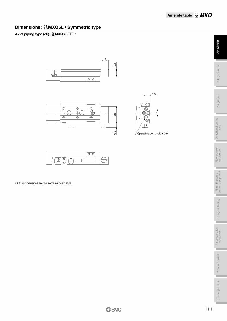
Operating port 2-M5 x 0.8
∗ Other dimensions are the same as basic style.
266.
3
5.5
12
111
Dimensions: MXQ6L / Symmetric type13-22-
Axial piping type (ø6): MXQ6L-��P13-22-
12.5
12
MXQAir slide table 13-22-
Air
cylin
der
Rot
ary
actu
ator
Air
grip
per
Dire
ctio
nal c
ontr
olva
lve
Fitt
ings
& T
ubin
gP
ress
ure
switc
hC
lean
gas
filte
rF
low
con
trol
equi
pmen
tF
ilter
, Pre
ssur
eco
ntro
l equ
ipm
ent
Air
prep
arat
ion
equi
pmen
t

Basic style
4-M3 x 0.5 thread depth 4
NA-M3 x 0.5 thread depth 3.5
Section AA Section BB
Extension end adjuster
Retraction end adjuster
ø30 depth 3+0.03 0
2N –1 x F
ø3H9 depth 3+0.025 0
Z
ZZ
Max. 11 (Retraction end adjuster)8IJ
12.5 5.7
6.5
(Ext
ensi
on e
nd a
djus
ter)
3.5
5.5
2 7
62327
3-M4 x 0.7 thread depth 6
1
22.5 (Extension end adjuster)
6.5
4
2-M3 x 0.5 thread depth 4
Operating port 2-M5 x 0.8
Vacuum suction port M5 x 0.8
6.5
12
24
5
10
4
N-M3 x 0.5 thread depth 5
16
16
321
36
6.5 3.5
1715
22.2
0.3
F
30
3
de
pth
3+
0.03
0
24 M
14.6K73.8
14.6KA73.8
4
23
ø6.
5
ø7ø3.
2
12.5 5.7
ø6.
5
ø7ø3.
2
NN-M4 x 0.7 thread depth 8
(NN–1) x H G
BH
A
4
HA GAB
A
143H
9
d
epth
3+0
.025
0
Model F252526324650
N446666
G7
14—88
31
H2528—312930
NN223344
I111012141312
J 1728405278
105
K23.533.543.553.563.588.5
Z 45.5 55.5 69.5 83.5108.5134.5
M 46 56 70 84109135
ZZ 71 81 95109134160
13-/22-MXQ8-1013-/22-MXQ8-2013-/22-MXQ8-3013-/22-MXQ8-4013-/22-MXQ8-5013-/22-MXQ8-75
(mm)
GA131429393761
HA192827315860
NA444488
KA————
82.5112.5
8
0.7
Note) Refer to the bottom view of 13-MXQ8-30.
Note) Note)
MXQAir slide table 13-22-
Dimensions: MXQ813-22-
Bottom view of MXQ8-3013-22-
112

∗ Other dimensions are the same as basic style.
Operating port 2-M5 x 0.8
316.
3
6.5
15
Dimensions: MXQ813-22-
Axial piping type (ø8): MXQ8-��P13-22-
MXQAir slide table 13-22-
14.5
12
113
Air
cylin
der
Rot
ary
actu
ator
Air
grip
per
Dire
ctio
nal c
ontr
olva
lve
Fitt
ings
& T
ubin
gP
ress
ure
switc
hC
lean
gas
filte
rF
low
con
trol
equi
pmen
tF
ilter
, Pre
ssur
eco
ntro
l equ
ipm
ent
Air
prep
arat
ion
equi
pmen
t
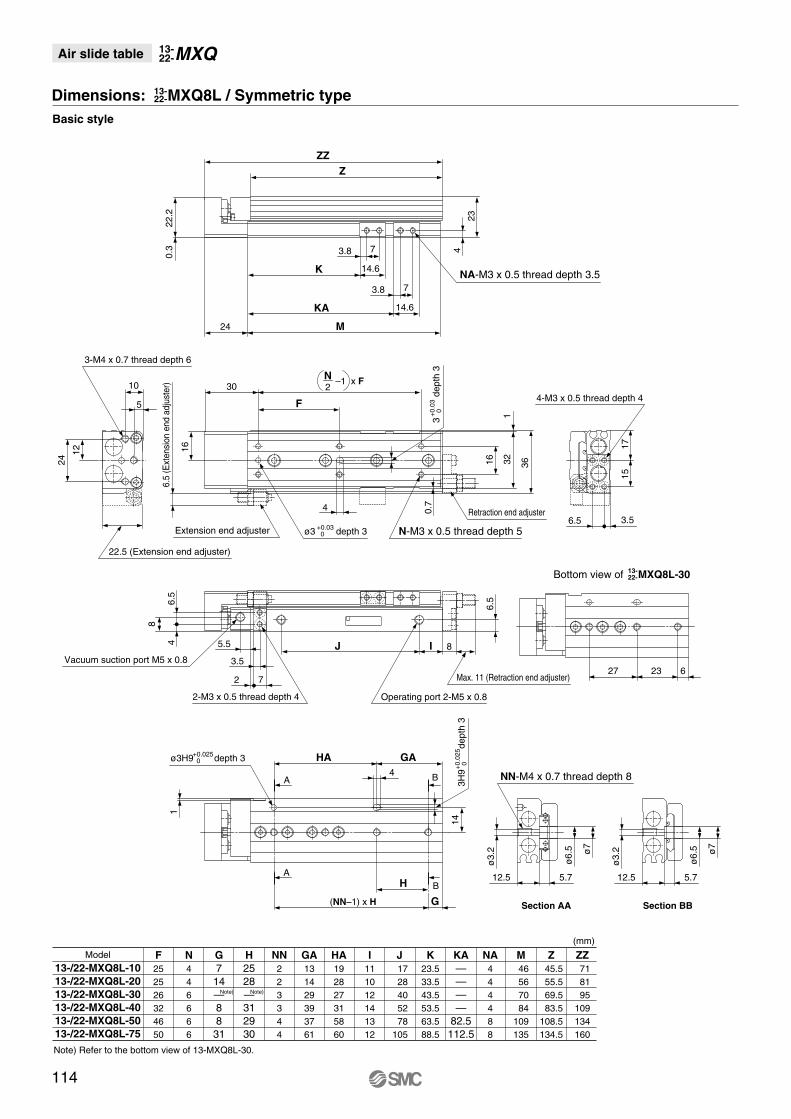
Basic style
4-M3 x 0.5 thread depth 4
NA-M3 x 0.5 thread depth 3.5
Section AA Section BB
Extension end adjuster
Retraction end adjuster
ø3 depth 3+0.03 0
3
d
epth
3+
0.03
0
ø3H9 depth 3+0.025 0
ZZZ
Max. 11 (Retraction end adjuster)
8IJ
6.5
(Ext
ensi
on e
nd a
djus
ter)
22.5 (Extension end adjuster)
3.5
5.5
2 762327
3-M4 x 0.7 thread depth 6
16.
54
8
2-M3 x 0.5 thread depth 4
Vacuum suction port M5 x 0.8
Operating port 2-M5 x 0.8
6.5
12
24
5
10
4
N-M3 x 0.5 thread depth 5
16
16
321
366.5 3.5
1715
22.2
0.3
F
2N –1 x F
30
24 M
14.6KA
14.6K
3.8 7
3.8 7
4
23
12.5 5.7
ø3.
2
ø6.
5 ø7
12.5 5.7
ø3.
2
ø6.
5 ø7
NN-M4 x 0.7 thread depth 8
(NN–1) x H G
BH
4
HA GA
BA
143H
9
d
epth
3+
0.02
5 0
Model F252526324650
N446666
G7
14—88
31
H2528—312930
NN223344
I111012141312
J 1728405278
105
K23.533.543.553.563.588.5
Z 45.5 55.5 69.5 83.5108.5134.5
M 46 56 70 84109135
ZZ 71 81 95109134160
13-/22-MXQ8L-1013-/22-MXQ8L-2013-/22-MXQ8L-3013-/22-MXQ8L-4013-/22-MXQ8L-5013-/22-MXQ8L-75
(mm)
GA131429393761
HA192827315860
NA444488
KA————
82.5112.5
0.7
A
Note) Refer to the bottom view of 13-MXQ8L-30.
Note) Note)
Bottom view of MXQ8L-3013-22-
MXQAir slide table 13-22-
Dimensions: MXQ8L / Symmetric type13-22-
114
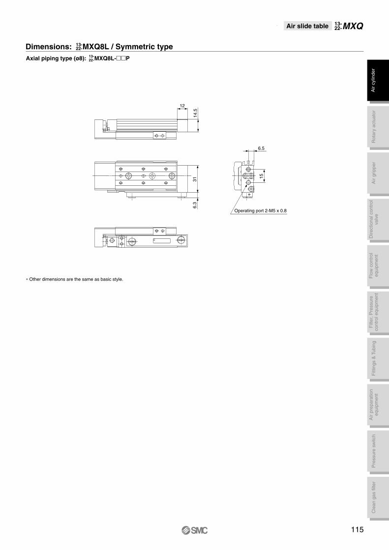
∗ Other dimensions are the same as basic style.
6.3
31
Operating port 2-M5 x 0.8
6.5
15
Dimensions: MXQ8L / Symmetric type13-22-
Axial piping type (ø8): MXQ8L-��P13-22-
MXQAir slide table 13-22-
12
14.5
115
Air
cylin
der
Rot
ary
actu
ator
Air
grip
per
Dire
ctio
nal c
ontr
olva
lve
Fitt
ings
& T
ubin
gP
ress
ure
switc
hC
lean
gas
filte
rF
low
con
trol
equi
pmen
tF
ilter
, Pre
ssur
eco
ntro
l equ
ipm
ent
Air
prep
arat
ion
equi
pmen
t

Basic style
4-M4 x 0.7 thread depth 6
NA-M4 x 0.7 thread depth 4
Section AA Section BB
Extension end adjuster
Retraction end adjusterø4H9 depth 4+0.030
0
ø4H9 depth 4+0.030 0
ZZZ
Max. 13 (Retraction end adjuster)10IJ
16 8
10 (
Ext
ensi
on e
nd a
djus
ter)
5.5
92939
3-M5 x 0.8 thread depth 8
1
29.5 (Extension end adjuster)
10
Vacuum suction port M5 x 0.8
Operating port 2-M5 x 0.8
8.5
14.5
29
5
13
5
N-M4 x 0.7 thread depth 5
20
19.5
392.
5
46
8 4.5
2220
29.2
0.3
F
2N –1 x F35
4H9
dep
th 4
+0
.030
0
27 M
18.5K8.55
18.5KA8.55
4.8
30
ø8.
5
ø9ø4.
2
16 8
ø8.
5
ø9ø4.
2
NN-M5 x 0.8 thread depth 10
(NN–1) x H G
BH
A
5
HA GA
BA
194H
9
d
epth
4+0
.030
0
Model F28283834343636
N 4 4 4 6 6 810
G181820—9
2312
H323240—393636
NN2223345
I12121415131717
J 34 34 42 58 70110135
K 26.5 36.5 46.5 56.5 66.5 91.5116.5
Z 66 66 76 93103147172
M 67 67 77 94104148173
ZZ 95 95105122132176201
13-/22-MXQ12- 1013-/22-MXQ12- 2013-/22-MXQ12- 3013-/22-MXQ12- 4013-/22-MXQ12- 5013-/22-MXQ12- 7513-/22-MXQ12-100
(mm)
GA18182038485984
HA32324039397272
NA4444488
KA—————
117.5142.5
1
Note) Refer to the bottom view of 13-MXQ12-40.
Note) Note)
Dimensions: 13-MXQ1213-22-
MXQAir slide table 13-22-
Bottom view of MXQ12-4013-22-
116

∗ Other dimensions are the same as basic style.
416.
3
Operating port 2-M5 x 0.8
8.5
20
Dimensions: MXQ1213-22-
Axial piping type (ø12): MXQ12-��P13-22-
MXQAir slide table 13-22-
13
16.5
117
Air
cylin
der
Rot
ary
actu
ator
Air
grip
per
Dire
ctio
nal c
ontr
olva
lve
Fitt
ings
& T
ubin
gP
ress
ure
switc
hC
lean
gas
filte
rF
low
con
trol
equi
pmen
tF
ilter
, Pre
ssur
eco
ntro
l equ
ipm
ent
Air
prep
arat
ion
equi
pmen
t

Basic style
Max. 13 (Retraction end adjuster)
10IJ
4-M4 x 0.7 thread depth 6
NA-M4 x 0.7 thread depth 4
Section AA Section BB
Extension end adjuster
Retraction end adjuster
ø4H9 depth 4+0.030 0
4H9
dep
th 4
+0.0
30 0
ø4H9 depth 4+0.030 0
Z
ZZ10
(E
xten
sion
end
adj
uste
r)
29.5 (Extension end adjuster)
5.5
92939
3-M5 x 0.8 thread depth 8
1
Vacuum suction port M5 x 0.8 Operating port 2-M5 x 0.8
8.5
14.5
29
5
13
5N-M4 x 0.7 thread depth 5
20 392.
5
46
8 4.5
2220
29.2
0.3
F2N –1 x F
35
27 M
18.5KA
18.5K
5 8.5
5 8.5
4.8 30
16 8
ø4.
2
ø8.
5 ø9
16 8
ø4.
2
ø8.
5 ø9
NN-M5 x 0.8 thread depth 10
(NN–1) x H G
BH
A
5
HA GA
BA
194H
9
d
epth
4+
0.03
0 0
Model F28283834343636
N 4 4 4 6 6 810
G181820—9
2312
H323240—393636
NN2223345
I12121415131717
J 34 34 42 58 70110135
K 26.5 36.5 46.5 56.5 66.5 91.5116.5
Z 66 66 76 93103147172
M 67 67 77 94104148173
ZZ 95 95105122132176201
13-/22-MXQ12L- 1013-/22-MXQ12L- 2013-/22-MXQ12L- 3013-/22-MXQ12L- 4013-/22-MXQ12L- 5013-/22-MXQ12L- 7513-/22-MXQ12L-100
(mm)
GA18182038485984
HA32324039397272
NA4444488
KA—————
117.5142.5
10
1
Note) Refer to the bottom view of 13-MXQ12L-40.
Note) Note)
19.5
MXQAir slide table 13-22-
Dimensions: MXQ12L / Symmetric type13-22-
Bottom view of MXQ12L-4013-22-
118

∗ Other dimensions are the same as basic style.
6.3
41
Operating port 2-M5 x 0.8
8.5
20
Dimensions: MXQ12L / Symmetric type13-22-
Axial piping type (ø12): MXQ12L-��P13-22-
MXQAir slide table 13-22-
13
16.5
119
Air
cylin
der
Rot
ary
actu
ator
Air
grip
per
Dire
ctio
nal c
ontr
olva
lve
Fitt
ings
& T
ubin
gP
ress
ure
switc
hC
lean
gas
filte
rF
low
con
trol
equi
pmen
tF
ilter
, Pre
ssur
eco
ntro
l equ
ipm
ent
Air
prep
arat
ion
equi
pmen
t

Basic style
4-M5 x 0.8 thread depth 7
NA-M5 x 0.8 thread depth 6.5
Section AA Section BB
Extension end adjuster
Retraction end adjusterø5H9 depth 5+0.030
0
ø5H9 depth 5+0.030 0
ZZZ
Max. 12 (Retraction end adjuster)12IJ
21 9
12.5
(Ext
ensi
on e
nd a
djus
ter)
133545
3-M6 x 1 thread depth 10
1
36.5 (Extension end adjuster)
Vacuum suction port M5 x 0.8
Operating port 2-M5 x 0.8
11
14.5
29
6.5
14
6
N-M5 x 0.8 thread depth 6
24
24.5
493.
5
58
11 5.5
2824
.5
35.7
0.3
F
2N –1 x F41
5H9
dep
th 5
+0.0
30 0
30 M
21K105.5
21KA105.5
5.5
37
ø9.
5
ø10
.5
ø5.
1
21 9
ø9.
5
ø10
.5
ø5.
1
NN-M6 x 1 thread depth 12
(NN–1) x H G
BH
A
6
HA GA
BA
245H
9
d
epth
5+0
.030
0
Model F3838485840464444
N 4 4 4 4 6 6 810
G18181919—213617
H39394858—524444
NN22223345
I1212121220151823
J 40 40 50 60 68105145165
K 28 38 48 58 68 93118143
Z 77 77 87 97113145188213
M 78 78 88 98114146189214
ZZ109109119129145177220245
13-/22-MXQ16- 1013-/22-MXQ16- 2013-/22-MXQ16- 3013-/22-MXQ16- 4013-/22-MXQ16- 5013-/22-MXQ16- 7513-/22-MXQ16-10013-/22-MXQ16-125
(mm)
GA 18 18 19 19 48 73 80105
HA3939485845528888
NA44448888
KA————91
123166191
5.5
11
1
Note) Refer to the bottom view of 13-MXQ16-50.
Note) Note)
MXQAir slide table 13-22-
Dimensions: MXQ1613-22-
Bottom view of MXQ16-5013-22-
120

∗ Other dimensions are the same as basic style.
526.
3
Operating port 2-M5 x 0.8
11
26
Dimensions: MXQ1613-22-
Axial piping type (ø16): MXQ16-��P13-22-
MXQAir slide table 13-22-
21
14
121
Air
cylin
der
Rot
ary
actu
ator
Air
grip
per
Dire
ctio
nal c
ontr
olva
lve
Fitt
ings
& T
ubin
gP
ress
ure
switc
hC
lean
gas
filte
rF
low
con
trol
equi
pmen
tF
ilter
, Pre
ssur
eco
ntro
l equ
ipm
ent
Air
prep
arat
ion
equi
pmen
t
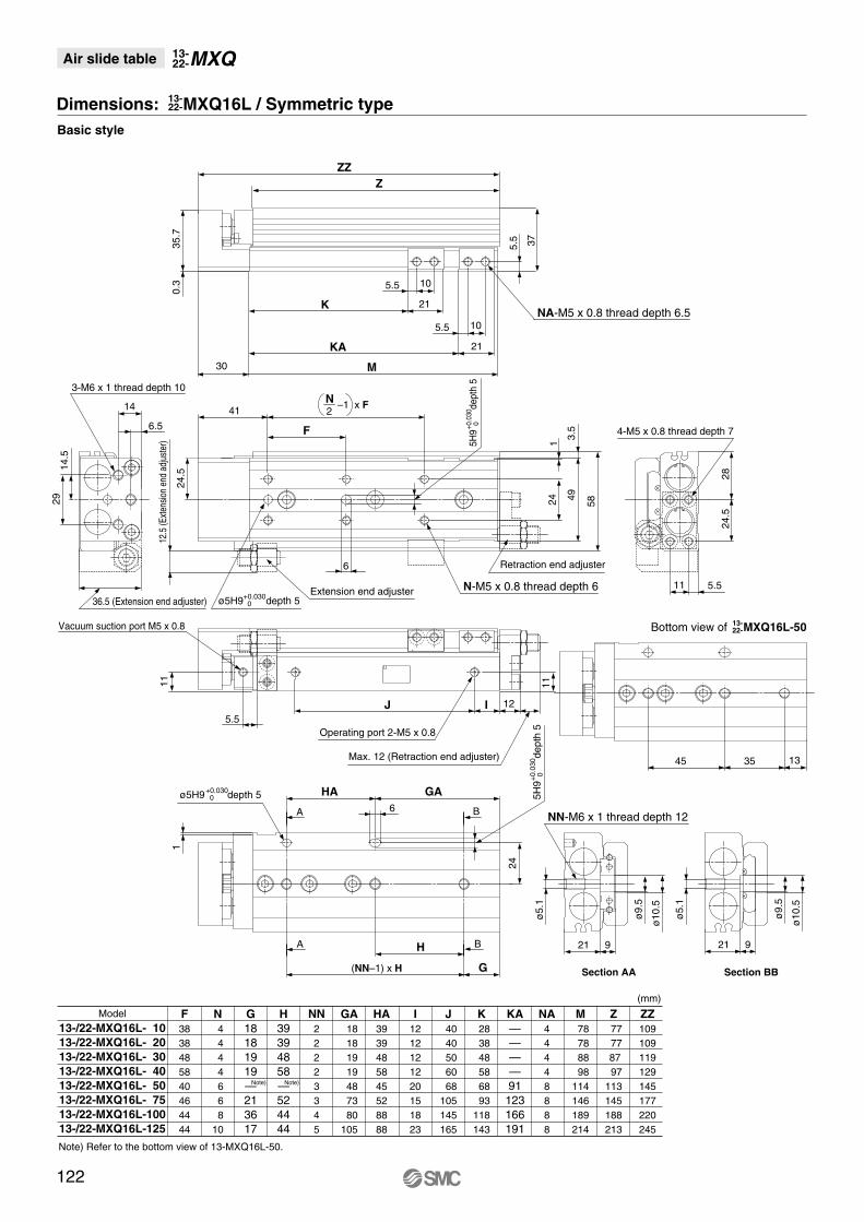
Basic style
Max. 12 (Retraction end adjuster)
12IJ
4-M5 x 0.8 thread depth 7
NA-M5 x 0.8 thread depth 6.5
Section AA Section BB
Extension end adjuster
Retraction end adjuster
ø5H9 depth 5+0.030 0
ø5H9 depth 5+0.030 0
ZZZ
12.5
(Ext
ensio
n en
d ad
just
er)
36.5 (Extension end adjuster)
5.5
3-M6 x 1 thread depth 10
1
Vacuum suction port M5 x 0.8
Operating port 2-M5 x 0.8
11
14.5
29
6.5
14
6
N-M5 x 0.8 thread depth 6
24
24.5
493.
5
5811 5.5
2824
.5
35.7
0.3
2N –1 x F
41
5H9
dep
th 5
+0.0
30 0
30 M
21KA
21K
5.5 10
5.5 10
5.5 37
21 9
ø5.
1
ø9.
5
ø10
.5
21 9
ø5.
1
ø9.
5
ø10
.5
NN-M6 x 1 thread depth 12
(NN–1) x H G
BHA
6
HA GA
BA
24
5H9
dep
th 5
+0.
030
0
Model F3838485840464444
N 4 4 4 4 6 6 810
G18181919—213617
H39394858—524444
NN22223345
I1212121220151823
J 40 40 50 60 68105145165
K 28 38 48 58 68 93118143
Z 77 77 87 97113145188213
M 78 78 88 98114146189214
ZZ109109119129145177220245
13-/22-MXQ16L- 1013-/22-MXQ16L- 2013-/22-MXQ16L- 3013-/22-MXQ16L- 4013-/22-MXQ16L- 5013-/22-MXQ16L- 7513-/22-MXQ16L-10013-/22-MXQ16L-125
(mm)
GA 18 18 19 19 48 73 80105
HA3939485845528888
NA44448888
KA————91
123166191
11
F
1
133545
Note) Refer to the bottom view of 13-MXQ16L-50.
Note) Note)
MXQAir slide table 13-22-
Dimensions: MXQ16L / Symmetric type13-22-
Bottom view of MXQ16L-5013-22-
122
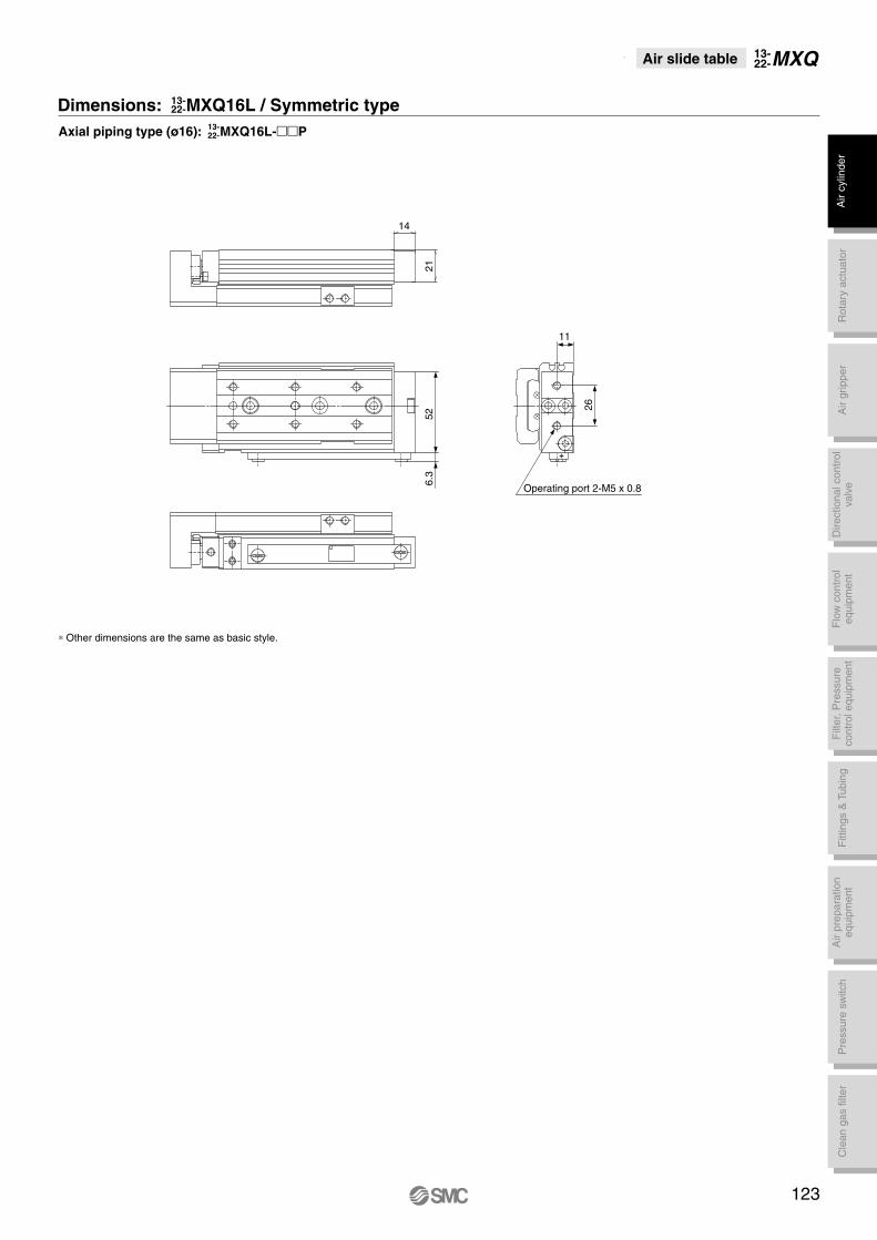
∗ Other dimensions are the same as basic style.
6.3
52
Operating port 2-M5 x 0.8
11
26
Dimensions: MXQ16L / Symmetric type13-22-
Axial piping type (ø16): MXQ16L-��P13-22-
MXQAir slide table 13-22-
21
14
123
Air
cylin
der
Rot
ary
actu
ator
Air
grip
per
Dire
ctio
nal c
ontr
olva
lve
Fitt
ings
& T
ubin
gP
ress
ure
switc
hC
lean
gas
filte
rF
low
con
trol
equi
pmen
tF
ilter
, Pre
ssur
eco
ntro
l equ
ipm
ent
Air
prep
arat
ion
equi
pmen
t

Basic style
4-M5 x 0.8 thread depth 8
NA-M6 x 1 thread depth 6
Section AA Section BB
Extension end adjuster
Retraction end adjuster
ø5H9 depth 5+0.030 0
ø5H9 depth 5+0.030 0
ZZZ
Max. 14 (Retraction end adjuster)13IJ
26 10.5
14.5
(Ext
ensi
on e
nd a
djus
ter)
7.5
123648
3-M6 x 1 thread depth 13
1.5
45.5 (Extension end adjuster)
14
Operating port 2-Rc, G, NPT1/8
Vacuum suction port Rc, G, NPT1/8
14
17.535
7
18
6
N-M5 x 0.8 thread depth 8
30
30
1.5
603
70
15 6
3331
43.5
0.5
F
2N –1 x F51
5H9
dep
th 5
+0.0
30 0
37 M
25K126.5
25KA126.5
6.5
46
ø9.
5
ø11ø5.
1
26 10.5
ø9.
5
ø11ø5.
1
NN-M6 x 1 thread depth 12
(NN–1) x H G
BH
A
6
HA GA
BA
29
5H9
dep
th 5
+0.0
30 0
Model F454048584255505562
N444466888
G22222222—17183756
H46464656—56565962
NN222233444
I161616161823251821
J 46 46 46 56 72100155190215
K 31 41 51 61 71 96121146171
Z 92.5 92.5 92.5102.5120.5153.5210.5238.5266.5
M 94 94 94104122155212240268
ZZ132132132142160193250278306
13-/22-MXQ20- 1013-/22-MXQ20- 2013-/22-MXQ20- 3013-/22-MXQ20- 4013-/22-MXQ20- 5013-/22-MXQ20- 7513-/22-MXQ20-10013-/22-MXQ20-12513-/22-MXQ20-150
(mm)
GA 18 18 18 22 48 73 74 96118
HA 50 50 50 56 48 56112118124
NA444448888
KA—————
126183211239
Note) Refer to the bottom view of 13-MXQ20-50.
Note) Note)
MXQAir slide table 13-22-
Dimensions: MXQ2013-22-
Bottom view of MXQ20-5013-22-
124

∗ Other dimensions are the same as basic style.
6511
.5
Operating port 2-Rc, G, NPT1/8
14
32
Dimensions: MXQ2013-22-
Axial piping type (ø20): MXQ20-��P13-22-
MXQAir slide table 13-22-
20
26
125
Air
cylin
der
Rot
ary
actu
ator
Air
grip
per
Dire
ctio
nal c
ontr
olva
lve
Fitt
ings
& T
ubin
gP
ress
ure
switc
hC
lean
gas
filte
rF
low
con
trol
equi
pmen
tF
ilter
, Pre
ssur
eco
ntro
l equ
ipm
ent
Air
prep
arat
ion
equi
pmen
t

Basic style
Max. 14 (Retraction end adjuster)
13IJ
4-M5 x 0.8 thread depth 8
NA-M6 x 1 thread depth 6
Section AA Section BB
Extension end adjuster
Retraction end adjuster
ø5H9 depth 5+0.030 0
ø5H9 depth 5+0.030 0
Z
ZZ
14.5
(E
xten
sion
end
adj
uste
r)
45.5 (Extension end adjuster)
7.5
123648
3-M6 x 1 thread depth 13
1.5
Vacuum suction port Rc, G, NPT1/8
Operating port 2-Rc, G, NPT1/8
14
17.5
35
7
18
6
N-M5 x 0.8 thread depth 8
30
30
1.5
603
70
15 6
3331
43.5
0.5
F2N –1 x F
51
5H9
dep
th 5
+0.0
30 0
37 M
25KA
25K
6.5 12
6.5 12
6.5 46
26 10.5
ø5.
1
ø9.
5
ø11
26 10.5
ø5.
1
ø9.
5
ø11
NN-M6 x 1 thread depth 12
(NN–1) x H G
BHA
6
HA GA
BA
29
5H9
dep
th 5
+0.
030
0
Model F454048584255505562
N444466888
G22222222—17183756
H46464656—56565962
NN222233444
I161616161823251821
J 46 46 46 56 72100155190215
K 31 41 51 61 71 96121146171
Z 92.5 92.5 92.5102.5120.5153.5210.5238.5266.5
M 94 94 94104122155212240268
ZZ132132132142160193250278306
13-/22-MXQ20L- 1013-/22-MXQ20L- 2013-/22-MXQ20L- 3013-/22-MXQ20L- 4013-/22-MXQ20L- 5013-/22-MXQ20L- 7513-/22-MXQ20L-10013-/22-MXQ20L-12513-/22-MXQ20L-150
(mm)
GA 18 18 18 22 48 73 74 96118
HA 50 50 50 56 48 56112118124
NA444448888
KA—————
126183211239
14
Note) Refer to the bottom view of 13-MXQ20L-50.
Note) Note)
MXQAir slide table 13-22-
Dimensions: MXQ20L / Symmetric type13-22-
Bottom view of MXQ20L-5013-22-
126

∗ Other dimensions are the same as basic style.
11.5
65
Operating port 2-Rc, G, NPT1/8
14
32
Dimensions: MXQ20L / Symmetric type13-22-
Axial piping type (ø20): MXQ20L-��P13-22-
MXQAir slide table 13-22-
20
26
127
Air
cylin
der
Rot
ary
actu
ator
Air
grip
per
Dire
ctio
nal c
ontr
olva
lve
Fitt
ings
& T
ubin
gP
ress
ure
switc
hC
lean
gas
filte
rF
low
con
trol
equi
pmen
tF
ilter
, Pre
ssur
eco
ntro
l equ
ipm
ent
Air
prep
arat
ion
equi
pmen
t

Basic style
6H9
dep
th 6
+0.
030
0
ZZZ
4-M6 x 1 thread depth 10
NA-M8 x 1.25 thread depth 8
Section AA Section BB
Extension end adjusterRetraction end adjusterø6H9 depth 6+0.030
0
ø6H9 depth 6+0.030 0
Max. 17 (Retraction end adjuster)15IJ
32 11.5
16.5
(Ext
ensio
n en
d ad
just
er)
7.5
225065
3-M8 x 1.25 thread depth 15
1.5
54.5 (Extension end adjuster)
17
Vacuum suction port Rc, G, NPT1/8
Operating port 2-Rc, G, NPT1/8
17
2244
6.5
21.5
7
N-M6 x 1 thread depth 11
36
37
1.5
743
84
20 6.5
4038
52.5
0.5
F
2N –1 x F
55.5
6H9
dep
th 6
+0.0
30 0
40.5 M
31K158
31KA158
855
35
ø11
ø12ø6.
6
32 11.5
ø11
ø12
NN-M8 x 1.25 thread depth 16
(NN–1) x H G
BH
A
7
HA GA
BA
Model F554655657560486065
N444446888
G2323232332—443156
H5555556580—446666
NN222223444
I161616161631201818
J 56 56 56 66 90100150205230
K 35 45 55 65 75100125150175
Z105.5105.5105.5115.5139.5164.5203.5256.5281.5
M107107107117141166205258283
ZZ148.5148.5148.5158.5182.5207.5246.5299.5342.5
13-/22-MXQ25- 1013-/22-MXQ25- 2013-/22-MXQ25- 3013-/22-MXQ25- 4013-/22-MXQ25- 5013-/22-MXQ25- 7513-/22-MXQ25-10013-/22-MXQ25-12513-/22-MXQ25-150
(mm)
GA 23 23 23 23 32 72 88 97122
HA 55 55 55 65 80 65 88132132
NA444444888
KA——————
170223248
ø6.
6
Note) Refer to the bottom view of 13-MXQ25-75.
Note) Note)
MXQAir slide table 13-22-
Dimensions: MXQ2513-22-
Bottom view of MXQ25-7513-22-
128

∗ Other dimensions are the same as basic style.
Dimensions: MXQ2513-22-
Axial piping type (ø25): MXQ25-��P13-22-
MXQAir slide table 13-22-
20
32
129
7911
.5
Operating port 2-Rc, G, NPT1/8
17
40
Air
cylin
der
Rot
ary
actu
ator
Air
grip
per
Dire
ctio
nal c
ontr
olva
lve
Fitt
ings
& T
ubin
gP
ress
ure
switc
hC
lean
gas
filte
rF
low
con
trol
equi
pmen
tF
ilter
, Pre
ssur
eco
ntro
l equ
ipm
ent
Air
prep
arat
ion
equi
pmen
t

Basic style
Max. 17 (Retraction end adjuster)
15IJ
4-M6 x 1 thread depth 10
NA-M8 x 1.25 thread depth 8
Section AA Section BB
Extension end adjuster
Retraction end adjusterø6H9 depth 6+0.030 0
ø6H9 depth 6+0.030 0
Z
ZZ16
.5 (E
xten
sion
end
adju
ster
)
54.5 (Extension end adjuster)
7.5
7
225065
3-M8 x 1.25 thread depth 15
1.5
17
Vacuum suction portRc, G, NPT1/8 Operating port 2-Rc, G, NPT1/8
2244
6.521.5
N-M6 x 1 thread depth 11
361.
5
743
8420 6.5
4038
52.5
0.5
F
2N -1 x F
55.5
6H9
dep
th 6
+0.0
30 0
40.5 M
31KA
31K
8 15
8 15
8
55
32 11.5
ø11 ø12
32 11.5
ø11 ø12
NN-M8 x 1.25 thread depth 16
(NN-1) x H G
BHA
7
HA GA
BA
3517
6H9
dep
th 6
+0.
030
0
Model F554655657560486065
N444446888
G2323232332—443156
H5555556580—446666
NN222223444
I161616161631201818
J 56 56 56 66 90100150205230
K 35 45 55 65 75100125150175
Z105.5105.5105.5115.5139.5164.5203.5256.5281.5
M107107107117141166205258283
ZZ148.5148.5148.5158.5182.5207.5246.5299.5342.5
13-/22-MXQ25L- 1013-/22-MXQ25L- 2013-/22-MXQ25L- 3013-/22-MXQ25L- 4013-/22-MXQ25L- 5013-/22-MXQ25L- 7513-/22-MXQ25L-10013-/22-MXQ25L-12513-/22-MXQ25L-150
(mm)
GA 23 23 23 23 32 72 88 97122
HA 55 55 55 65 80 65 88132132
NA444444888
KA——————
170223248
ø6.
6
ø6.
6
Note) Refer to the bottom view of 13-MXQ25L-75.
Note) Note)
37
MXQAir slide table 13-22-
Dimensions: MXQ25L / Symmetric type13-22-
Bottom view of MXQ25L-7513-22-
130

∗ Other dimensions are the same as those of basic style. 11
.579
Operating port 2-Rc, G, NPT1/8
17
40
Dimensions: MXQ25L / Symmetric type13-22-
Axial piping type (ø25): MXQ25L-��P13-22-
MXQAir slide table 13-22-
20
32
131
Air
cylin
der
Rot
ary
actu
ator
Air
grip
per
Dire
ctio
nal c
ontr
olva
lve
Fitt
ings
& T
ubin
gP
ress
ure
switc
hC
lean
gas
filte
rF
low
con
trol
equi
pmen
tF
ilter
, Pre
ssur
eco
ntro
l equ
ipm
ent
Air
prep
arat
ion
equi
pmen
t
Made to Order
1. Anti-corrosive specifications for guide unit -X42
MXQ Standard model no. -X4213-22-
Martensitic stainless steel is used for table and guide block. Use this treatment if more effective anti-corrosiveness is necessary.Table and guide block are given anti-corrosive treatment Note 2).
Note 1) Dimensions are the same as standard type.Note 2) Special anti-corrosive treatment makes table and the
guide block black.
13-MXQ Standard model no. -X52
Fluoro rubber is used for the dust cover and the dust plug instead of silicone rubber for standard one.
Note 1) Dimensions are the same as standard type.
Extension end stroke adjuster mounting screw
Extension end stroke adjuster
(Generates particles because it is through the body.)
In case the extension end stroke adjuster is removed, plug the mounting hole.Particle generation may occur because the bottom hole of the mounting screw penetrates the body. Consult SMC for more information.
Applicable bore size (mm) 12, 16, 20, 25
Dust plug
Dust cover
In case of types without extension end adjuster, the hole is plugged with a hexagon socket head set screw at the time of shipment.
Hexagon socket head set screw
2. Dust cover and dust plug made by fluoro rubber -X52
Operating Precautions
Specific Product PrecautionsBe sure to read before handling.
Caution