air toxics operating procedure
TRANSCRIPT

Air Toxics Operating Procedure
By
Beth Friedman and James Laing
For the
Air Quality Program
Washington State Department of Ecology Olympia, Washington
August 2021, Publication 18-02-012

Publication Information This document is available on the Department of Ecology’s website at: https://fortress.wa.gov/ecy/publications/summarypages/1802012.html
Contact Information Air Quality Program
P.O. Box 47600 Olympia, WA 98504-7600 Phone: 360-407-6800 Website1: Washington State Department of Ecology
ADA Accessibility The Department of Ecology is committed to providing people with disabilities access to information and services by meeting or exceeding the requirements of the Americans with Disabilities Act (ADA), Section 504 and 508 of the Rehabilitation Act, and Washington State Policy #188.
To request an ADA accommodation, contact Ecology by phone at 360-407-6800 or email at [email protected]. For Washington Relay Service or TTY call 711 or 877-833-6341. Visit Ecology's website for more information.
1 www.ecology.wa.gov/contact

Department of Ecology’s Regional Offices Map of Counties Served
Region Counties served Mailing Address Phone
Southwest Clallam, Clark, Cowlitz, Grays Harbor, Jefferson, Mason, Lewis, Pacific, Pierce, Skamania, Thurston, Wahkiakum
PO Box 47775 Olympia, WA 98504 360-407-6300
Northwest Island, King, Kitsap, San Juan, Skagit, Snohomish, Whatcom
PO Box 330316 Shoreline, WA 98133 206-594-0000
Central Benton, Chelan, Douglas, Kittitas, Klickitat, Okanogan, Yakima
1250 W Alder St Union Gap, WA 98903 509-575-2490
Eastern Adams, Asotin, Columbia, Ferry, Franklin, Garfield, Grant, Lincoln, Pend Oreille, Spokane, Stevens, Walla Walla, Whitman
4601 N Monroe Spokane, WA 99205 509-329-3400
Headquarters Across Washington PO Box 46700 Olympia, WA 98504 360-407-6000
Air Toxics Operating Procedure
Air Quality Program Washington State Department of Ecology
Olympia, WA
July 2021 | Publication 18-02-012

Approved by:
Signature: Date: Arati Kaza, Ecology Quality Assurance Officer
Signature: Date: Rob Dengel, Air Quality Deputy Program Manager
Signature: Date: Sean Lundblad, Technical Services Section Manager
Signature: Date: Jill Schulte, Air Monitoring Coordinator
Signature: Date: Scott Dubble, NWRO/SWRO & Air Quality Operations Unit Supervisor
Signature: Date: Beth Friedman, Air Quality Program Quality Assurance Coordinator
Signatures are not available on the Internet version
Publication 18-02-012 Air Toxics Procedure Page 6 Revised August 2021
Table of Contents List of Figures and Tables ....................................................................................................................................... 8
Figures ....................................................................................................................................................................... 8
Tables ........................................................................................................................................................................ 8
1. Overview ...................................................................................................................................................... 9
1.1. Purpose and scope ..................................................................................................................................... 9
1.2. Data quality objectives ............................................................................................................................... 9
1.3. Health and safety ...................................................................................................................................... 12
2. VOCs ........................................................................................................................................................... 12
2.1. Introduction .............................................................................................................................................. 12
2.2. Principles of operation ............................................................................................................................. 12
2.3. Equipment and supplies ........................................................................................................................... 14
2.4. Siting and installation ............................................................................................................................... 14
2.5. Sample setup, collection, and storage ...................................................................................................... 14
2.6. Quality control and maintenance ............................................................................................................. 16 2.6.1. Quality control ..................................................................................................................................... 16
2.7. Data validation and quality assurance ...................................................................................................... 17 2.7.1. Data validation ..................................................................................................................................... 17 2.7.2. Quality assurance................................................................................................................................. 18
3. Carbonyls .................................................................................................................................................... 18
3.1. Introduction .............................................................................................................................................. 18
3.2. Principles of operation ............................................................................................................................. 18
3.3. Equipment and supplies ........................................................................................................................... 19
3.4. Siting and installation ............................................................................................................................... 19
3.5. Sample setup, collection, and storage ...................................................................................................... 20
3.6. Quality control and maintenance ............................................................................................................. 23 3.6.1. Quality control ..................................................................................................................................... 23
3.7. Data validation and quality assurance ...................................................................................................... 25 3.7.1. Data validation ..................................................................................................................................... 25 3.7.2. Quality assurance................................................................................................................................. 25
4. PAHs ........................................................................................................................................................... 25
4.1. Introduction .............................................................................................................................................. 25
4.2. Principles of operation ............................................................................................................................. 26
4.3. Equipment and supplies ........................................................................................................................... 27
4.4. Siting and installation ............................................................................................................................... 27

Publication 18-02-012 Air Toxics Procedure Page 7 Revised August 2021
4.5. Sample setup, collection, and storage ...................................................................................................... 27 4.5.1. Cartridge assembly .............................................................................................................................. 28 4.5.2. Cartridge install .................................................................................................................................... 29 4.5.3. Cartridge retrieval ................................................................................................................................ 29
4.6. Quality control and maintenance .................................................................................................................................... 30 4.6.1. Quality control ..................................................................................................................................... 30
4.7. Data validation and quality assurance ...................................................................................................... 33 4.7.1. Data validation ..................................................................................................................................... 33 4.7.2. Quality assurance................................................................................................................................. 33
5. PM10 Metals ................................................................................................................................................ 34
5.1. Introduction .............................................................................................................................................. 34
5.2. Principles of operation ............................................................................................................................. 35
5.3. Equipment and supplies ........................................................................................................................... 35
5.4. Siting and installation ............................................................................................................................... 35
5.5. Sample collection and storage.................................................................................................................. 35
5.6. Quality control and maintenance ............................................................................................................. 36 5.6.1. Quality control ..................................................................................................................................... 36
5.7. Data validation and quality assurance ...................................................................................................... 36 5.7.1. Data validation ..................................................................................................................................... 36 5.7.2. Qualiy assurance .................................................................................................................................. 37
6. References .................................................................................................................................................. 37
Appendix ............................................................................................................................................................. 38
Sample VOC Chain of Custody Data Sheet .............................................................................................................. 38
Sample VOC Quality Control Check Form ............................................................................................................... 39
Sample NATTS Carbonyl Chain of Custody Data Sheet ........................................................................................... 40
Sample PAMS Carbonyl Chain of Custody Data Sheet ............................................................................................ 41
Sample Carbonyl Quality Control Check Form ........................................................................................................ 42
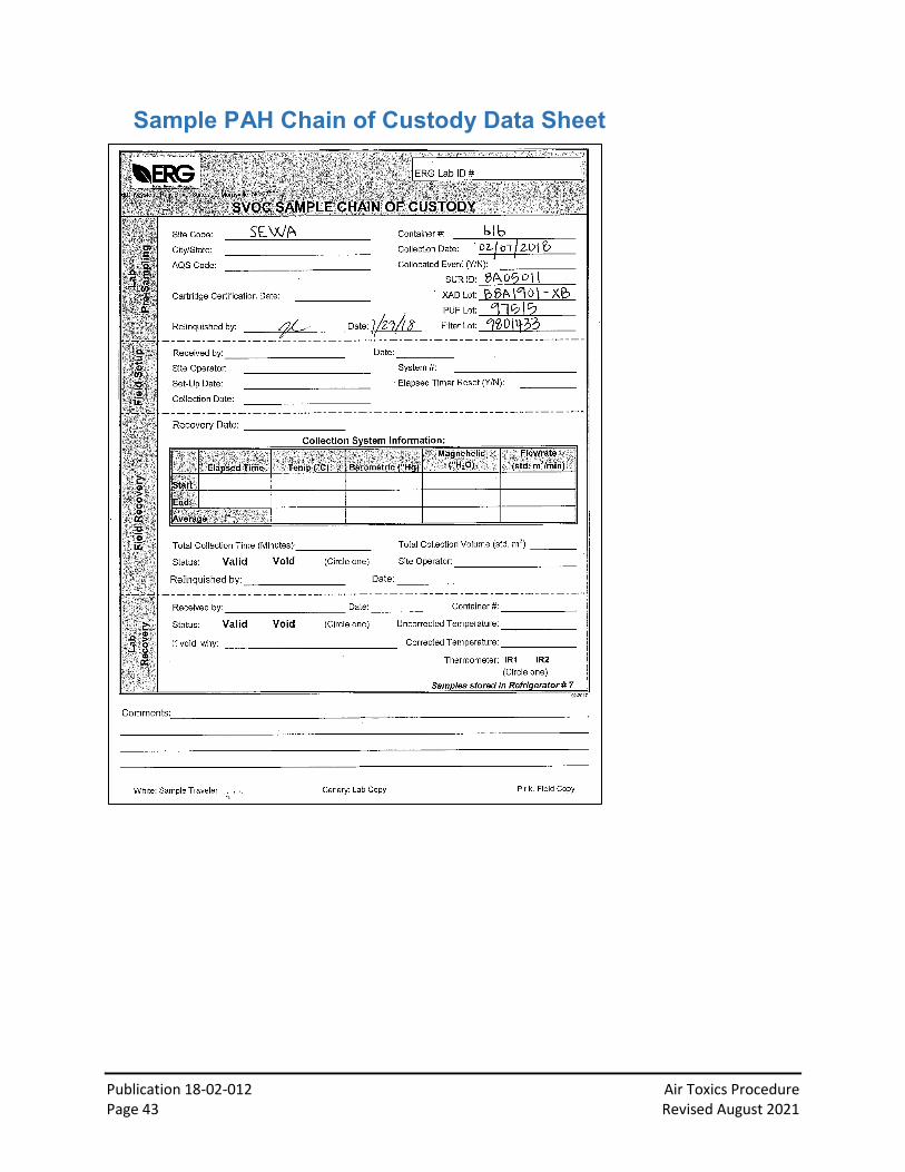
Sample PAH Chain of Custody Data Sheet .............................................................................................................. 43
Sample PAH Quality Control Check Form ............................................................................................................... 44
Sample PM10 Metals Quality Control Check Form .................................................................................................. 45

Publication 18-02-012 Air Toxics Procedure Page 8 Revised August 2021
List of Figures and Tables
Figures
Figure 1: SUMMA® electropolished stainless steel canister ........................................................ 13 Figure 2: Xonteck 901 Canister Sampler front panel (top) and rear panel (bottom) ................... 13 Figure 3: Run (left), Status (middle), and Schedule (right) menus on the front panel control .... 15 Figure 4: ATEC Model 8000-3 ....................................................................................................... 19 Figure 5: Schedules tab on the ATEC 8000 interface .................................................................... 21 Figure 6: Setup tab on the ATEC 8000 interface ........................................................................... 22 Figure 7: Manual tab on the ATEC 8000 interface ........................................................................ 24 Figure 8: The Tisch Environmental TE-1000 PUF Sampler at the Beacon Hill site ........................ 26 Figure 9: Components of the PUF Sampler................................................................................... 27 Figure 10: Separated dual chamber sampling head (left) and particulate filter holder (right). ... 28 Figure 11: Calibration orifice unit ................................................................................................. 31 Figure 12: Example calibration worksheet ................................................................................... 34
Tables
Table 1: Summary of required equipment and supplies. Required calibration equipment specific to each instrument are listed in their respective chapter. ............................................................. 9 Table 2: Analytes of Interest for the NATTS Program................................................................... 10 Table 3: Summary of required quality control checks and maintenance for VOCs ..................... 16 Table 4: PAMS Carbonyls 8-hour sample collection times ........................................................... 19 Table 5: Summary of required quality control checks and maintenance for carbonyls .............. 23 Table 6: Summary of required quality control checks and maintenance for PAHs ...................... 30 Table 7: Summary of required quality control checks and maintenance for PM10 metals .......... 36

Publication 18-02-012 Air Toxics Procedure Page 9 Revised August 2021
1. Overview 1.1. Purpose and scope
This document describes Ecology’s procedures for monitoring air toxics as part of the National Air Toxics Trends Station (NATTS) Program for Volatile Organic Compounds (VOCs), carbonyl compounds, polycyclic aromatic hydrocarbons (PAHs), and PM10 metals. This document also describes Ecology’s procedures for the collection of carbonyl compounds for the EPA Photochemical Assessment Monitoring Stations (PAMS) network. Monitoring of these species within the Washington State Ambient Air Monitoring Network must be conducted in accordance with the procedures described herein. These procedures are intended to be used with the model-specific information and instructions provided by the instrument manufacturer as well as with Ecology’s Air Toxics Monitoring Quality Assurance Project Plan (QAPP), Ecology’s PAMS Quality Assurance Project Plan (QAPP), and the wider Washington Network Quality Assurance Plan (QAP).
This standard operating procedure (SOP) describes the installation, operation, quality control, QA, maintenance, and data collection and storage for the air toxic instrumentation. Table 1 lists the supported instrumentation that is directly applicable to this SOP. For the purposes of this SOP and associated instrumentation utilized at Ecology’s urban National Core Monitoring Network (NCore) site, the contract laboratory refers to Eastern Research Group, Inc.
Table 1: Summary of required equipment and supplies. Required calibration equipment specific to each instrument are listed in their respective chapter.
Equipment type Pollutant Equipment
Instrument VOC Xonteck Model 901 Canister Sampler
Carbonyl ATEC 8000 Carbonyl Sampler
PAH Tisch Environmental TE-1000 PUF Poly-Urethane Foam High Volume Air Sampler
PM10 metals Partisol FEM Model 2025 Sequential Air Sampler
1.2. Data quality objectives Ecology conducts air toxics monitoring primarily at its urban NCore site. The primary data quality objectives (DQOs) for the NATTS program are described in detail in the NATTS Technical Assistance Document and involve detecting trends in hazardous air pollutant (HAP) concentrations across rolling three-year periods within acceptable levels of decision error by doing the following:
• Measure concentrations of the NATTS Tier I (required) and Tier II (highly desired) analytes (Table 2).

Publication 18-02-012 Air Toxics Procedure Page 10 Revised August 2021
• Consistently generate data of sufficiently high and known quality, with methods of sufficient sensitivity to obtain limits of detection at or lower than concentrations at which adverse health effects have been observed.
• Collect sufficient data to represent the annual average ambient concentrations of air toxics.
Table 2: Analytes of Interest for the NATTS Program.
Hazardous Air Pollutant (HAP) Analyte class Tier
Acrolein VOC I
Tetrachloroethylene VOC I
Benzene VOC I
carbon tetrachloride VOC I
Chloroform VOC I
Trichloroethylene VOC I
1,3-butadiene VOC I
vinyl chloride VOC I
Acetonitrile VOC II
Acrylonitrile VOC II
Bromoform VOC II
carbon disulfide VOC II
Chlorobenzene VOC II
Chloroprene VOC II
p-dichlorobenzene VOC II
cis-1,3-dichloropropene VOC II
trans-1,3-dichloropropene VOC II
ethyl acrylate VOC II
ethyl benzene VOC II
hexachloro-1,3-butadiene VOC II
methyl ethyl ketone VOC II
methyl isobutyl ketone VOC II
methyl methacrylate VOC II
methyl tert-butyl ether VOC II

Publication 18-02-012 Air Toxics Procedure Page 11 Revised August 2021
Hazardous Air Pollutant (HAP) Analyte class Tier
methylene chloride VOC II
Styrene VOC II
1,1,2,2-tetrachloroethane VOC II
Toluene VOC II
1,1,2-trichloroethane VOC II
1,2,4-trichlorobenzene VOC II
m&p-xylenes VOC II
o-xylene VOC II
Formaldehyde Carbonyl I
Acetaldehyde Carbonyl I
Naphthalene PAH I
benzo(a)pyrene PAH I
Acenaphthene PAH II
Acenaphthylene PAH II
Anthracene PAH II
benz(a)anthracene PAH II
benzo(b)fluoranthene PAH II
benzo(e)pyrene PAH II
benzo(k)fluoranthene PAH II
Chrysene PAH II
dibenz(a,h)anthracene PAH II
Fluoranthene PAH II
Fluorine PAH II
indeno(1,2,3-cd)pyrene PAH II
Phenanthrene PAH II
Pyrene PAH II
Nickel PM10 Metal I
Arsenic PM10 Metal I
Cadmium PM10 Metal I

Publication 18-02-012 Air Toxics Procedure Page 12 Revised August 2021
Hazardous Air Pollutant (HAP) Analyte class Tier
Manganese PM10 Metal I
Beryllium PM10 Metal I
Lead PM10 Metal I
Antimony PM10 Metal II
Chromium PM10 Metal II
Cobalt PM10 Metal II
Selenium PM10 Metal II
1.3. Health and safety Compressed gases – Care should be taken to follow established safety practices when working with compressed gases.
Instrument maintenance – Instrument operators should take precaution when working within the instrument chassis as contact with exposed wires and electrical connections can result in electrical shock. The carbonyl sampler ozone denuder is maintained at ≥ 50°C, therefore contact with the denuder oven should be avoided.
Glass manifolds – When cleaning, assembling, or installing glass manifolds, site operators should avoid use of excessive force, which can break or shatter the glass tubing resulting in lacerations.
2. VOCs 2.1. Introduction
This chapter describes Ecology’s procedures for collecting VOC samples using the Xonteck 901 Canister sampler at its NCore site in Seattle, WA. This chapter includes procedures for installation, operation, quality control, maintenance, and data storage. It is intended to be used in concert with the manufacturer’s model-specific operation manual.
2.2. Principles of operation Ambient air is drawn into certified, clean 6 liter SUMMA® electropolished stainless steel canisters (Figure 1). The canisters are received from the contract laboratory under vacuum. Samples are collected for 24 hours every six days. A diaphragm pump pressurizes the canister up to 15 psi; a mass flow controller maintains a constant flow of 7 sccm throughout the programmed sampling time. The system meets the specifications of the EPA TO-15 method. After sampling, canisters are shipped under pressure to the national contract laboratory; VOCs are identified and quantified by gas chromatography-mass spectrometry within 30 days of collection.
Publication 18-02-012 Air Toxics Procedure Page 13 Revised August 2021
An internal computer in the sampler controls sample scheduling. Time, data, pre-purge delay, flow rate, pump and canister pressure, sampling schedule, and power failure errors are displayed on the front panel display; an associated hard copy is printed on the front panel-mounted printer at the end of each sample period (Figure 2).
Figure 1: SUMMA® electropolished stainless steel canister
Figure 2: Xonteck 901 Canister Sampler front panel (top) and rear panel (bottom)

Publication 18-02-012 Air Toxics Procedure Page 14 Revised August 2021
2.3. Equipment and supplies In addition to the equipment in Table 1, the contract laboratory provides clean 6 liter SUMMA canisters and chain of custody data sheets (Appendix 7.1). Certified flow and pressure standards are required for calibration. A 2 micrometer sintered stainless steel particulate filter is required for installation at the sampler inlet.
2.4. Siting and installation The sampler should be located in an area of unobstructed airflow and away from the direction of any sources. The sampling probe should be placed 2-15 meters above ground level, and should be composed of chromatographic grade stainless steel or borosilicate glass. Power requirements are 115V/60Hz. Sample line tubing (preferably stainless steel) should be kept as short as possible to ensure residence time in the tubing is less than 20 seconds; use of PTFE Teflon is not recommended due to the adsorption potential of its surface. A 2 micrometer pore size sintered stainless steel particulate filter must be installed at the sampler inlet port. The filter should be replaced annually, or more frequently if ambient particle concentrations are high and decreased flows or collected canister pressures are observed.
Collocated sampler inlets should be placed within 2-4 meters horizontally and less than or equal to 3 meters vertically. They should also be no closer than 1 meter from low-volume (~ greater than or equal to 16.7 lpm) and 2 meters from high-volume (greater than 100 lpm) particulate or PAH samplers.
2.5. Sample setup, collection, and storage The contract laboratory will send closed, capped SUMMA® canisters to be used in sampling as well as chain of custody data sheets. Follow the steps below to conduct sampling.
1. Before removing the stainless steel cap on the canister for installation, ensure the canister valve is closed.
2. Connect the sample output line from the sampler to the canister, tightening one eighth turn past finger tight. Do not overtighten.
3. Ensure that the sampler “inlet” and “bypass” fittings on the rear of the sampler are not capped or blocked.
4. Before opening the canister valve, conduct a leak check. Navigate to the “Run” menu on the front panel of the instrument and select “Leak Check” (Figure 3). Select “Run” to begin the leak check. At the end of the test, the value for the flow rate should read close to 0.0 in-Hg (< 0.5 in-Hg) and the screen should display “Leak Check Passed”. Note that this will cause the line to be pressurized. Before opening the canister valve make sure that the line is no longer pressurized.
a. If the leak check fails, check the connection from the sampler to the canister. Attempt to isolate the leak by removing the tubing to the canister and capping the outlet of the sampler; perform the leak check again. If the leak check fails again, there is likely an issue with the sample pump. If the leak check passes, the

Publication 18-02-012 Air Toxics Procedure Page 15 Revised August 2021
leak is likely within the tubing and connection to the canister. If unable to isolate the leak, or if the leak is likely due to a faulty mass flow controller, remove the instrument from sampling and contact Ecology’s Calibration and Repair Lab.
5. Open the canister valve; canisters must show greater than 28 in-Hg vacuum to conduct sampling. Prior to shipping to Ecology, canisters are evacuated to approximately 30 in-Hg at the contract laboratory (will be noted on chain of custody data sheet). Note: a leak check can also be conducted by observing the pressure gauge on the front panel for 5 minutes after opening the canister valve. The pressure should not change by more than 0.2 psi over the 5 minute time period.
6. Schedule the sampling event by navigating to the “Schedule” screen (Figure 3). Enter the time and duration in military PST. Canister samples should run for 24 (±1) hours. Clocks should be within ±5 minutes of reference time (GPS, cell phone).
7. Clear the sample data from the previous run by navigating to the “Status” screen and pushing “clr”. The elapsed time, volume, average flow, and starting and ending pressure will repopulate with the scheduled run’s data.
8. Enter the initial canister pressure and flow setting on the chain of custody data sheet in the “Field Setup” section. Note that the elapsed timer is reset and the canister valve is open.
9. After the sampling event, collect canisters as soon as possible, at a maximum within 72 hours of the conclusion of the sampling event. The “Status” screen on the front panel (Figure 3) shows the elapsed time, volume collected, average flow, start pressure, and end pressure. Close the canister valve, re-install the cap on the canister, and note the final canister pressure on the chain of custody data sheet (generally 7-10 psi). Prior to shipping to the contract laboratory, the canister can be kept at room temperature.
10. Hard copies of the chain of custody data sheets must be kept at an off-site location for a minimum of six years.
Figure 3: Run (left), Status (middle), and Schedule (right) menus on the front panel control

Publication 18-02-012 Air Toxics Procedure Page 16 Revised August 2021
2.6. Quality control and maintenance Table 3: Summary of required quality control checks and maintenance for VOCs
Procedure Required frequency Time check Every sample event Leak check Every sample event Flow check Every 90 days Flow calibration Initially, if flow checks deviate >10% (one point) or >5%
(multi-point slope and intercept Pressure gauge check Annually Certification check Initially, annually Clean/replace tubing to manifold Annually Replace sintered particulate filter Annually
2.6.1. Quality control Verify that the sampling unit clock (shown on the front panel) is within ±5 minutes of the reference time with each sample collection event.
The sampler pressure gauge must be assessed annually to be within ±0.5 psi of the certified standard.
Prior to initial field deployment, and annually thereafter, each VOC sampling unit must be certified as non-biasing of both a sample of hydrocarbon-free zero air and a known concentration of a VOC standard in air. These zero- and known-standard certification checks can be done at the national contract laboratory.
Document QC checks in the electronic logbook.
2.6.1.1. Leak check
A leak check must be conducted before every sampling event. With a canister installed and the valve closed, ensure that the sampler “inlet” and “bypass” fittings on the back of the instrument are not capped or blocked. Navigate to the “Run” menu on the front panel of the instrument and select “Leak Check” (Figure 3). Select “Run” to begin the leak check. The value for the leak check should read close to 0.0 in-Hg (< 0.5 in-Hg) and the screen should display “Leak Check Passed”. Note that this will cause the line to be pressurized. Before opening the canister valve make sure that the line is no longer pressurized.
A leak check can also be conducted by opening and closing the canister valve repeatedly; the vacuum should not change by more than 0.2 psi over a 5 minute interval.
If the leak check fails, check the connection from the sampler to the canister. Attempt to isolate the leak by removing the tubing to the canister and capping the outlet of the sampler; perform

Publication 18-02-012 Air Toxics Procedure Page 17 Revised August 2021
the leak check again. If the leak check fails again, there is likely an issue with the sample pump. If the leak check passes, the leak is likely within the tubing and connection to the canister.
2.6.1.2. Flow check and calibration
One-point flow check
At a minimum, a one-point flow check must be conducted every 90 days (EPA recommends monthly) to certify the sample flow is within ±10% of the flow from a certified standard. Navigate to the “Run” screen and push the “Calibration” button. Attach a flow standard to the “output” fitting on the back panel of the instrument. On the front panel, set the sampling flow rate to be audited, select the “start” button to turn on the pump, and open the channel valve. Once stable, record the indicated instrument flow and the measured flow from the flow standard on the QC form. At a flow rate of 7 sccm, the flow check passes if the percent difference between the indicated flow and the measured flow is within 10%.
Multi-point flow check and calibration
If the one-point flow check indicates a failure, a multi-point calibration flow check must be conducted by pushing the “Corrected” button on the “Calibrate” screen (the “Corrected” button color will turn green). The flow audit screen displays 5 set flow points. These points can be changed by selecting each set point to display the number keypad on the front panel. Before making any changes or starting the flow check, record the previous slope and intercept from the last flow calibration. Push the “Start” button to being the flow check. Once the flow stabilizes, select “Next” and enter the reading from the flow standard. Repeat for the other set flow points. The instrument will calculate and display a new slope and intercept. Re-calibrate the instrument if the new slope and intercept is not within ±5% of the previous.
To enter the flow calibration mode from the “Calibration” screen, turn the “Corrected” button off (its color will turn gray). The flow calibration screen displays 5 set flow points. These points can be changed by selecting each set point to display the number keypad on the front panel. Press “Start” to begin the calibration. Once the flow stabilizes, select “Next” and enter the reading from the flow standard. Repeat for the other set flow points. The instrument will calculate and display a new slope and intercept. Select “Save” and record the new values in the electronic logbook. Press “Exit” to return to the main menu.
Enter the QC results on the QC form and document them in the electronic logbook. An example QC form is in Appendix 7.2. Send an electronic copy (pdf) of the completed QC form to the Quality Assurance Coordinator within 10 days of completing the QC.
2.7. Data validation and quality assurance 2.7.1. Data validation
The station operator conducts preliminary data validation every 30 days by screening based on instrument metrics and QC results. Reasons for anomalies (i.e., wildfires, power outages) are

Publication 18-02-012 Air Toxics Procedure Page 18 Revised August 2021
noted on the chain of custody data sheets and in the electronic logbook. Hard copies of the chain of custody data sheets are retained at an off-site location for at least 6 years.
The contract laboratory conducts validation of the analytical data.
2.7.2. Quality assurance All quality control check results and electronic logbook entries will be reviewed by quality assurance personnel on a monthly basis to ensure adherence to the requirements of this SOP and the Air Toxics Monitoring Quality Assurance Project Plan (QAPP). Following quantification of the VOC data by the contract laboratory, quality assurance personnel conduct a secondary review of laboratory-provided data.
Air Quality Program quality assurance personnel conduct an independent annual performance evaluation consisting of a leak check and a flow audit. QA personnel follow a process similar to that described in section 2.6.1Quality Control.
3. Carbonyls 3.1. Introduction
This chapter describes Ecology’s procedures for collecting carbonyl samples using the ATEC 8000 for carbonyl compounds with 2,4-dinitro-phenylhydrazine (DNPH) coated silica gel sorbent cartridges. This chapter includes procedures for installation, operation, quality control, QA, maintenance, and data storage. It is intended to be used in concert with the manufacturer’s model-specific operation manual.
3.2. Principles of operation The ATEC 8000 cartridge sampler unit is shown in Figure 4. The system meets the specifications of the EPA Compendium Method TO-11A. A measured volume of ambient air is pulled by a vacuum pump through a KI ozone denuder to remove ozone, which interferes with both the collection and analysis of the carbonyls. Once the sampled air is scrubbed of ozone it passes through a silica gel sorbent cartridge impregnated with DNPH where carbonyls in the sampled air stream react with DNPH to form stable carbonyl hydrazones. These stable carbonyl hydrazones are maintained within the sorbent bed until extraction at the analysis laboratory.
For NATTS, samples are collected for 24 hours every six days year-round. NATTS samples start at 12:00 midnight. For PAMS, three consecutive 8-hour samples starting are collected every three days June 1 –August 31. The PAMS sample times are in Table 4. These samples are offset to better capture morning and afternoon concentrations. Sample cartridges must be extracted for analysis within 14 days of collection.

Publication 18-02-012 Air Toxics Procedure Page 19 Revised August 2021
Table 4: PAMS Carbonyls 8-hour sample collection times
PAMS Sample ID Sample times PAMS Sample 1 04:00-12:00 (noon) PAMS Sample 2 12:00 (noon)-20:00 PAMS Sample 3 20:00-04:00
During offline analysis at a contract laboratory, the hydrazone-carbonyl derivatives are eluted from the sampling cartridges using acetonitrile and are quantified by high performance liquid chromatography (HPLC) with a UV detector at a wavelength of 360 nm as described in EPA Compendium Method TO-11A. The carbonyl concentrations in the ambient air sample are calculated from the measured concentrations in the sample extracts and the volume of air sampled through the cartridge.
PAMS laboratories are required to measure and report the priority compounds formaldehyde and acetaldehyde and are encouraged to measure and report acetone and benzaldehyde.
Figure 4: ATEC Model 8000-3
3.3. Equipment and supplies In addition to the equipment in Table 1, the contract laboratory provides DNPH-coated sorbent cartridges (Sep-Pak) and chain of custody data sheets (NATTS: Appendix 7.3; PAMS: Appendix 7.4). Refer to the Technical Assistance Document for requirements if using commercial cartridges from another source. Powder-free nitrile gloves, adjustable wrench, and icepacks for shipping are also necessary. A certified flow standard is required for calibration.
3.4. Siting and installation The sampler should be located on a level surface in an area of unobstructed airflow away from any sources. The sampling probe should be placed 2-15 meters above ground level, and be composed of chromatographic grade stainless steel or borosilicate glass. Consideration must be

Publication 18-02-012 Air Toxics Procedure Page 20 Revised August 2021
given to the length of the sampling inlet line to ensure that the residence time is kept to 20 seconds or less. Consideration should also be given to minimize intrusion of particulate matter (PM) and water into the sampling line, which can effectively be reduced by inverting the inlet and installing a rain shield (such as inverted funnel) on the inlet probe. For connections to an inlet manifold, the sampling unit inlet can be connected to any port on the manifold. Connections must be leak-free to ensure that sampled air is from the ambient atmosphere entering the inlet probe. Power requirements are 115VAC, 15A. Collocated sampler inlets should be placed within 2-4 meters horizontally and less than or equal to 3 meters vertically.
An ozone denuder or scrubber must be installed in the sampling unit flow path upstream of the DNPH-coated cartridges. Ozone may react with DNPH and/or hydrazone-carbonyl derivatives, leading to an underestimation of carbonyl concentrations as well as degraded carbonyl compounds that may interfere chromatographically with target analytes. A copper tubing denuder/scrubber is the preferred ozone removal method for the NATTS program, and is described in Method TO-11A and the Technical Assistance Document for the National Air Toxics Trends Stations Program (Revision 3). The ATEC 8000 ozone KI ozone denuder is internally located.
To avoid sampling interferences, place the instrument pump outside the shelter, away from all other instrument probes. Inside the shelter, avoid using newly built furniture, as some carbonyl compounds can off-gas from newly built plywood tables or shelves.
3.5. Sample setup, collection, and storage Follow the steps below to setup, schedule sampling, collect, and ship samples.
1. To eliminate stagnant air and flush the tubing, the inlet line to the sampling unit should be purged with ambient air (equivalent of a minimum of 10 air changes) prior to the start of sample collection.
2. Wear gloves when installing the cartridges. Prior to the sampling event (preferably the day before), remove the Sep-Pak cartridge(s) from the foil pouch transport containers and remove the caps from both ends. Place the cartridges in the appropriate channel tubes and tighten the cartridge holders properly. Place the cartridge caps in the foil pouch transport containers for sample retrieval. For sites running both NATTS and PAMS, a three channel carbonyls sampler (ATEC 8000-3) is required. Channel 1 has 8 ports and is used for PAMS samples, channel 2 is used for NATTS samples, channel 3 is used for duplicate NATTS samples, and the blank channel is used for blank samples. If NATTS and PAMS blank samples are to be run on the same date, one of the blank samples should be placed in a port on channel 1 which is not scheduled to run.
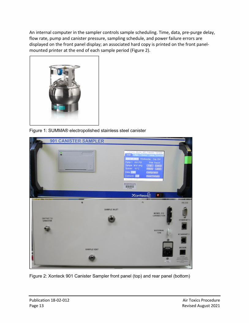
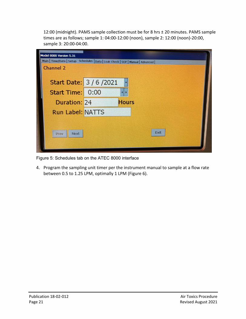
3. To schedule a sampling event, use the touch screen to select the “Schedules” tab. Use “Prev” and “Next” buttons to select the appropriate Ports on Channel 1 (Port 1-8) or secondary channels (Channel 2-3). Input the correct start date, start time, sample duration, and run label (Figure 5). Once set press “Exit” and the sample period is saved. The NATTS sample collection must for 24 ±1 hours. NATTS sample collection starts at
Publication 18-02-012 Air Toxics Procedure Page 21 Revised August 2021
12:00 (midnight). PAMS sample collection must be for 8 hrs ± 20 minutes. PAMS sample times are as follows; sample 1: 04:00-12:00 (noon), sample 2: 12:00 (noon)-20:00, sample 3: 20:00-04:00.
Figure 5: Schedules tab on the ATEC 8000 interface
4. Program the sampling unit timer per the instrument manual to sample at a flow rate between 0.5 to 1.25 LPM, optimally 1 LPM (Figure 6).

Publication 18-02-012 Air Toxics Procedure Page 22 Revised August 2021
Figure 6: Setup tab on the ATEC 8000 interface
5. A leak check must be conducted prior to each sample collection event. The ATEC 8000-series sampling units automatically perform a leak check prior to every sample collection during the first 30 seconds of the collection and will flag samples that exceed the factory default criterion. If a leak check fails (the default leak check acceptance criterion for ATEC 8000-series sampling units is < 0.03 lpm flow), recheck cartridge connections for tightness, tubing cracks, and loose fittings. Inspect cartridges to ensure there are not cracks in the cartridge housing which could cause a leak. If necessary, install cartridges on alternative channels that do not exhibit leaks. Repeated leak check failures following corrective steps may indicate a tubing failure inside the sampling unit such as may occur due to holes in tubing caused by vibration of tubing against an interior component. Document the leak check outcome on the sample collection form.
6. Prior to retrieving samples from the sampling unit, review the recorded sample collection data from the sampling unit display to ensure that sampling occurred according to the intended program. Record any discrepancies (e.g. low flow conditions, power failures, leak check failures, etc., as indicated by flags or error messages) on the sample collection form. For sampling units so equipped (e.g., ATEC 8000-series sampling units), it is highly recommended to transfer sample collection data to an external drive for later review and archive.

Publication 18-02-012 Air Toxics Procedure Page 23 Revised August 2021
7. Retrieve the sample(s) no later than 72 hours after the sampling event, preferably within 48 hours. Wearing gloves, remove the Sep-Pak cartridge(s), reinstall the caps, and return the cartridge(s) to the foil pouch transport container(s).
8. Place the cartridges in cold storage (≤ 4 °C) and ship overnight to the contract laboratory for analysis with the ice packs supplied by the contract laboratory. If sample retrieval occurs on a Friday, keep the cartridges in cold storage (≤ 4 °C) over the weekend and ship the following Monday. Ensure that personnel are available at the contract laboratory to receive the sample the following day after overnight shipping.
3.6. Quality control and maintenance Table 5: Summary of required quality control checks and maintenance for carbonyls
Procedure Required frequency Time check Every sample event Leak check Prior to each sample event Flow check Every 30 days Clean (with DI water) or replace tubing to manifold Annually Replace Ozone denuder Annually Replace the particulate filter Annually Positive bias check Initially, annually Flow Calibration Initially, annually
3.6.1. Quality control Verify that the sampling unit clock is within 5 minutes of the reference time with each sample collection event. A leak check is completed automatically by the ATEC 8000 before every sample, and will also be done monthly. Enter the QC results on the QC form and document them in the electronic logbook. An example QC form is in Appendix 7.5.
3.6.1.1. Positive bias check
Prior to deployment and annually thereafter, the sampling unit is to be challenged with humidified zero air and a sample collected to demonstrate the sampling unit does not contribute to positive bias in measured concentrations. The positive bias check is preferably performed following instrument maintenance, which would include recharging or replacing the denuder, replacing particulate filter(s), replacing sample cartridge connection tubing, and calibrating the MFC(s). The national contract laboratory can conduct this positive bias check.
3.6.1.2. Flow calibration
Prior to deployment and annually thereafter, and following failure of a flow verification check, the MFC(s) in the sampling unit is calibrated by standardization against a NIST-traceable flow transfer standard covering flows that bracket the desired flow range of the sampling unit. MFCs are to be calibrated at flows corrected to standard conditions of 760 mmHg and 25°C. (Note that some sampling units default to standard conditions of 760 mmHg and 0°C as provided from the factory and may revert following power outages. The temperature reference

Publication 18-02-012 Air Toxics Procedure Page 24 Revised August 2021
must be corrected to 25°C.). The flow rate slope and intercept are set according to the manufacturer’s procedures for calibrating the sampling unit flows. Once the calibration is established, the flow at the desired setting is measured with the flow transfer standard and will be within ±10% of the flow setting.
The national contract laboratory can conduct this flow calibration.
3.6.1.3. Flow calibration verification
Monthly, the flow of the sampling unit is verified by comparison to a NIST-traceable certified flow transfer standard. The measured flow must be within ±10% of the flow indicated by the sampling unit or recalibration is necessary. Once a flow standard is connected to the selected channel or port, conduct a flow check in the “Manual” tab on the ATEC 8000 interface by selecting the appropriate channel, inlet valve, and pump. Figure 7 shows a flow check being conducted on Port 1 (Channel 1). Site operators should immediately notify the agency QA representative of the failed flow calibration check to ensure that previously collected sample data are appropriately qualified (flagged). Enter the QC results on the QC form and document them in the electronic logbook. An example QC form is in Appendix 7.5. Send an electronic copy (pdf) of the completed QC form to the Quality Assurance Coordinator within 10 days of completing the QC.
Figure 7: Manual tab on the ATEC 8000 interface
3.6.1.4. Field blank samples
Field blank cartridges should remain in their sealed foil pouch until removed for exposure at the monitoring site. Field blanks characterize the contribution of contamination due to field handling activities and installation in the sampling unit, and do not characterize the

Publication 18-02-012 Air Toxics Procedure Page 25 Revised August 2021
contamination that occurs due to the exposure of the cartridge between cartridge installation and retrieval. To collect the field blank sample, install the cartridge in the sampling unit on an active sampling port employed for field sample collection, maintain the cartridge in the sampling unit for five to ten minutes, and retrieve as would be done for an ambient sample. Place the caps on the field blank cartridge inlet and outlet, seal the capped cartridge into the foil pouch, and store the field blank under refrigeration (≤ 4°C) as soon as possible (note – Refrigerated storage may not be possible until retrieval of ambient samples) until shipped to the laboratory.
3.7. Data validation and quality assurance 3.7.1. Data validation
The station operator conducts preliminary data validation by screening data, instrument metrics and QC results. Reasons for anomalies (i.e., wildfires, power outages) will be noted on the chain of custody data sheets and in the electronic logbook. Copies of the chain of custody data sheets are retained at on off-site location for at least 6 years.
The contract laboratory conducts validation of the analytical data.
3.7.2. Quality assurance All quality control check results and electronic logbook entries will be reviewed by quality assurance personnel on a monthly basis to ensure adherence to the requirements of this SOP and the Air Toxics Monitoring Quality Assurance Project Plan (QAPP). Following quantification of the carbonyl data by the contract laboratory, quality assurance personnel conduct a secondary review of laboratory-provided data.
Quality assurance personnel conduct an independent annual performance evaluation consisting of a leak check and a flow audit. QA personnel follow a procedure similar to that described in section 3.6.1.
4. PAHs 4.1. Introduction
This chapter describes Ecology’s procedures for sampling polycyclic aromatic hydrocarbons (PAHs) using a Tisch Environmental TE-1000 PUF Poly-Urethane Foam (PUF) High Volume Air Sampler (Figure 8). This chapter includes procedures for installation, operation, quality control, maintenance, and data storage. It is intended to be used in concert with the manufacturer’s model-specific operation manual (https://tischenv-tischenvironment.netdna-ssl.com/wp-content/uploads/2015/07/TE-1000-PUF-Manual.pdf).

Publication 18-02-012 Air Toxics Procedure Page 26 Revised August 2021
Figure 8: The Tisch Environmental TE-1000 PUF Sampler at the Beacon Hill site
4.2. Principles of operation The PUF sampler is composed of an aluminum shelter, dual chamber sampling head, flow venturi, magnehelic gauge, elapsed time indicator, blower motor, exhaust hose, and seven-day mechanical timer (Figure 9). The upper chamber of the dual chamber sampling head contains the 110 mm diameter Micro-Quartz particulate filter while the lower chamber consists of the glass cartridge containing styrene-divinylbenzene polymer resin sorbent (XAD-2 or equivalent) for trapping PAHs. Approximately 200-350 cubic meters of ambient air are drawn through the dual chamber sampling head. A contract laboratory conducts offline speciation and quantification analysis by gas chromatography-mass spectrometry.
Samples are collected for 24 hours every six days. The mechanical timer is utilized to schedule sampling in advance and the elapsed time indicator measures the total sampling time. The aluminum shelter protects the sampler from precipitation. The system meets the specifications of EPA Compendium Method TO-13A.

Publication 18-02-012 Air Toxics Procedure Page 27 Revised August 2021
Figure 9: Components of the PUF Sampler
Clockwise from upper left: Dual chamber sampling head, flow venturi for calibration, mechanical timer, magnehelic gauge. Photos from Tisch Environmental
4.3. Equipment and supplies In addition to the equipment in Table 1, the contract laboratory provides the XAD-2 resin, particulate filter, and chain of custody data sheets (Appendix 7.6). An empty glass cartridge, digital manometer, and an orifice calibration unit (TE-5040A) are needed for calibration and QC checks.
4.4. Siting and installation Install the sampler on a level service 2-15 meters above ground level. The inlet must be 2 meters from all other sampling inlets. Ensure the sampler is clear from nearby obstructions. The horizontal distance from the sampler to the closest vertical obstruction higher than the sampler should be at least twice the height of the vertical obstruction. The motor exhaust tube should terminate in the predominant downwind direction minimally 3 meters away from the sampling unit. Collocated samplers must be within 2-4 meters horizontally, with inlets within 1 meter vertically. The sampler requires 110V/15A service from a grounded electrical outlet. Protect the power connection from precipitation by placing it in the shelter or wrapping it with plastic tape.
4.5. Sample setup, collection, and storage

Publication 18-02-012 Air Toxics Procedure Page 28 Revised August 2021
4.5.1. Cartridge assembly The contract laboratory ships the particulate filter (packaged in a plastic petri dish sealed with Teflon tape) and glass cartridge containing the XAD-2 resin/PUF in a chilled cooler. The cartridge will be wrapped and sealed on both ends with clean aluminum foil.
Install the sampling media in the PUF sampler as close to the sampling date as possible. Loading the sampling media into the dual chamber sampling head should occur in a clean indoor environment. If loading the sampling head off-site, cover the outlet port of the sampling head with cleaned aluminum foil and install the sampling head cover to protect the particulate filter from contamination.
Wear powder-free nitrile gloves when loading the sampling media into the dual chamber sampling head. Separate the two chambers of the sampling head by unscrewing the cartridge holder from the filter holder base and detaching the filter retaining ring from the filter holding by loosening the wing nuts on the pivot screw posts. Place the components on a clean surface (Figure 10).
Figure 10: Separated dual chamber sampling head (left) and particulate filter holder (right).
Remove the glass cartridge from its transport packaging. Save the bubble wrap and aluminum foil for post-sampling retrieval. Insert the glass cartridge into the cartridge holder, ensuring that the fritted end is pointed downward. Screw the cartridge holder into the filter holder. Rotate the filter holder just a small amount past tight; do not over-tighten.
Remove the filter from the petri dish. Using the provided tweezers, place the particulate filter in the filter holder in between two Teflon gaskets (Figure 10). Lift the pivot screw posts up into position and tighten each wing nut slightly past hand-tight.

Publication 18-02-012 Air Toxics Procedure Page 29 Revised August 2021
4.5.2. Cartridge install Open the sampler cover by removing the pin from the latch on top of the sampler housing. Place the sampler head quick-connect fitting into the sampler quick-connect fitting and lock the connection using the levers. Open the lower part of the sampler (with the magnehelic gauge and timer) to record the current elapsed time reading on the sample data sheet. Record the initial reading on the magnehelic gauge. Close the roof of the shelter and run the sampler for 5 minutes. Record the magnehelic gauge reading on the chain of custody data sheet. This initial reading should correspond to a flow rate of at least 0.226 m3 min-1. Turn off the sampler and set the mechanical timer to sample from midnight to midnight local time for the prescribed sampling day.
4.5.3. Cartridge retrieval Retrieve the sample preferably within 24 hours of the sampling event, and no more than 72 hours after the conclusion of the sampling event. This is especially important in hot weather to minimize the evaporative loss of the more volatile compounds.
Record the final elapsed time on the chain of custody data sheet. Elapsed time should be within 23-25 hours. Turn on the sampler and allow the motor to warm up for 5 minutes; record the magnehelic gauge reading on the sample data sheet. The final flow rate must be within 10% of the initial flow rate for the sample to be valid. Record the average temperature and pressure from the sample day—this can be obtained from a variety of sources. Calculate the total flow rate and record on the chain of custody data sheet using the following equation; multiply by the total time (minutes) to obtain the average sample volume (m3):
𝑄𝑄𝑠𝑠𝑠𝑠𝑠𝑠 = 𝑚𝑚−1 ���(𝑚𝑚𝑚𝑚𝑚𝑚𝑚𝑚) �𝑃𝑃𝑎𝑎𝑎𝑎760
� �298𝑇𝑇𝑎𝑎𝑎𝑎
�� − 𝑏𝑏�
Qstd: flow (m3 min-1) m: sampler slope b: sampler intercept Magn: average magnehelic gage reading tav: daily average temperature (K) pav: daily average pressure (mm-Hg)
Wearing gloves, disconnect the cartridge from the sampling unit; place its cover on top to protect the particulate filter and cover the outlet with aluminum foil. Transport to a clean indoor environment to disassemble. Avoid transporting the sampling head in a non-upright position. If sampler disassembly occurs more than 10 minutes after retrieval, store and transport the sampling head refrigerated.
Wearing gloves, separate the two chambers of the sampling head and place the glass thimble cartridge on a clean surface. Remove the filter with the provided tweezers and fold into fourths with the particulate matter inward. Insert the folded filter into the glass thimble cartridge with

Publication 18-02-012 Air Toxics Procedure Page 30 Revised August 2021
the sorbent media. Storage in the glass cartridge minimizes disturbance of particulate matter on the filter, as any losses stay within the PUF inside the glass thimble. Wrap the glass cartridge in the clean aluminum foil that it arrived in and place back in the bubble wrap and container for shipping. Store and ship the container at ≤ 4°C using the ice packs supplied by the contract laboratory.
4.5.3.1. Field blank management
Assemble a field blank sample following the same procedure for an ambient sample. Install field blanks into the secondary sampling unit for at least 5 minutes. Store and ship as a normal sample (≤ 4°C).
4.6. Quality control and maintenance
Table 6: Summary of required quality control checks and maintenance for PAHs
Procedure Frequency Flow check Every 90 days Siting Verification Annually Clean sampling heads, inspect gaskets Every 90 days Inspect electrical connections, check timers for proper operation, remove debris from sampling unit
Weekly
Replace motors and motor brushes As needed (generally 6-8 months) Certify calibration orifice Annually
Flow calibration Initially, after motor maintenance, >10% flow deviation from the calibration standard
4.6.1. Quality control 4.6.1.1. Flow calibration
Conduct flow calibrations initially, after any motor maintenance, and when flow verification checks deviate by more than 10% from the flow transfer standard flow or design flow. At a minimum, conduct one-point flow checks every 90 days. The calibration orifice unit (Figure 11) should be certified annually.

Publication 18-02-012 Air Toxics Procedure Page 31 Revised August 2021
Figure 11: Calibration orifice unit
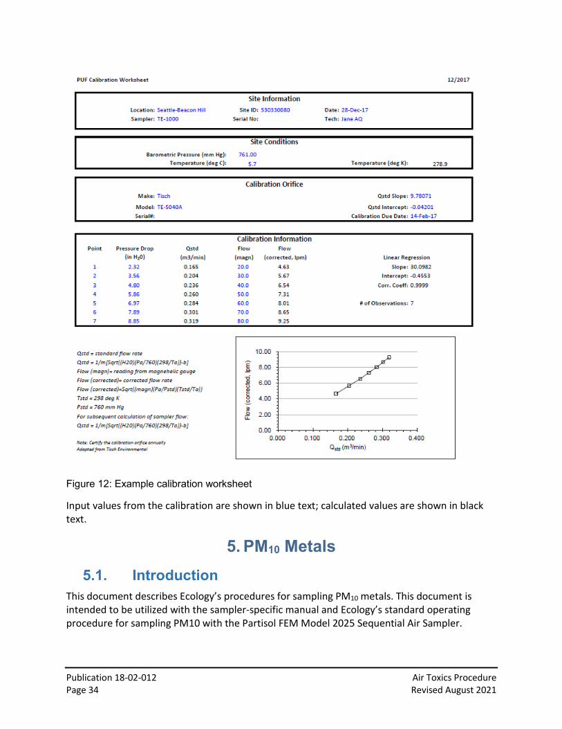
Use the following steps to establish a unique calibration relationship. A calibration worksheet adapted from a calibration worksheet provided by Tisch Environmental (www.tisch-env.com/calibration-worksheets) is shown in Figure 12.
1. Use an empty glass cartridge (no foam plug or filter paper in the sampling module) with an identical frit to the sampling frit.
2. Install the TE-5040A calibration orifice on top of the 110 mm filter holder.
3. Connect tubing from the manometer port to the pressure tap on the calibrator.
4. Open the ball valve fully (handle should be straight up). This is located inside the shelter directly above the blower motor.
5. Turn the system on by switching the manual switch on the timer. Allow the motor to warm up for 5 minutes.
6. Use 80 inches of water as the first calibration point. Record the orifice manometer reading on the data sheet.
7. Close the ball valve slightly to readjust the dial gage to 60 inches. Record the corresponding orifice manometer reading on the data sheet.
8. Continue to adjust the ball valve for readings at 50, 40, and 30 inches. Record the corresponding manometer readings on the data sheet. Note that the readings do not have to be exactly 80, 60, 50, 40, and 30 inches as long as the minimally five calibration points bracket the sample rate (approximately 60 inches for the Beacon Hill sampler).
9. Turn the sampler off and remove the manometer and calibration assembly.

Publication 18-02-012 Air Toxics Procedure Page 32 Revised August 2021
10. Use the calibration worksheet to calculate the slope and intercept for the sampler. Note that the calibration utilizes standard flows—the ambient temperature and pressure during calibration should also be recorded and the worksheet calculates standard air flows using the following equation:
𝑄𝑄𝑠𝑠𝑠𝑠𝑠𝑠 = 𝑚𝑚−1 ���(𝐻𝐻2𝑂𝑂) �𝑃𝑃𝑎𝑎
760� �
298𝑇𝑇𝑎𝑎
�� − 𝑏𝑏�
Qstd: standard flow rate indicated by the calibrator orifice (m3 min-1)
H2O: orifice manometer reading during calibration (inches H2O)
Ta: ambient temperature during calibration (K)
298: standard temperature (K)
Pa: ambient barometric pressure during calibration (mm-Hg)
760: standard barometric pressure (mm-Hg)
m: Qstandard slope of orifice calibration relationship
b: Qstandard intercept of orifice calibration relationship
11. The magnehelic gage readings during the calibration are corrected to the current meteorological conditions using the following equation:
𝐹𝐹𝐹𝐹𝑂𝑂𝐹𝐹 (𝑐𝑐𝑐𝑐𝑐𝑐𝑐𝑐𝑐𝑐𝑐𝑐𝑐𝑐𝑐𝑐𝑐𝑐) = ��(𝑚𝑚𝑚𝑚𝑚𝑚𝑚𝑚) �𝑃𝑃𝑎𝑎
760� �
298𝑇𝑇𝑎𝑎
��
FLOW (corrected): magnehelic gage readings corrected to temperature and pressure during calibration
Magn: magnehelic gage readings during calibration
12. The calibration worksheet will produce a plot of FLOW (corrected) vs. Qstd, and a slope, intercept and correlation coefficient are calculated using least squares regression. If the correlation coefficient is at least 0.990, the calibration is valid, and future sampler flow rates can be calculated using the new regression slope (m) and regression intercept (b) in the equation in section 4.5.3.
13. Quarterly, verify the flow by conducting a one-point flow check using the steps outlined above. Re-calibrate the flow if the flow verification check deviates by more than 10% from the expected flow given the calibration.
Publication 18-02-012 Air Toxics Procedure Page 33 Revised August 2021
Enter the QC results on the QC form and document them in the electronic logbook. An example QC form is in Appendix 7.7. Send an electronic copy (pdf) of the completed QC form to the Quality Assurance Coordinator within 10 days of completing the QC.
4.6.1.2. Annual verification of siting
Annually, verify the following siting criteria:
• 270° unobstructed probe inlet • Inlet is 2-15 meters above ground level • Inlet is greater than 10 meters from the drip line of the nearest tree • Collocated sampling inlet is 2-4 meters from primary sampling unit inlet (horizontally)
4.7. Data validation and quality assurance 4.7.1. Data validation
The station operator conducts initial data validation by screening data based on instrument metrics and QC results. Reasons for anomalies (i.e., wildfires, power outages) are noted on the chain of custody data sheets and in the electronic logbook. Copies of the chain of custody data sheets are retained off-site for at least 6 years.
The contract laboratory conducts validation of the analytical data.
4.7.2. Quality assurance All quality control check results and electronic logbook entries will be reviewed by quality assurance personnel on a monthly basis to ensure adherence to the requirements of this SOP and the Air Toxics Monitoring Quality Assurance Project Plan (QAPP). Following quantification of the PAH data by the contract laboratory, quality assurance personnel conduct a secondary review of laboratory-provided data.
Quality assurance personnel conduct an annual performance evaluation consisting of a flow check. QA assurance personnel follow a procedure similar to that described in section 4.6.1.
Publication 18-02-012 Air Toxics Procedure Page 34 Revised August 2021
Figure 12: Example calibration worksheet
Input values from the calibration are shown in blue text; calculated values are shown in black text.
5. PM10 Metals 5.1. Introduction
This document describes Ecology’s procedures for sampling PM10 metals. This document is intended to be utilized with the sampler-specific manual and Ecology’s standard operating procedure for sampling PM10 with the Partisol FEM Model 2025 Sequential Air Sampler.

Publication 18-02-012 Air Toxics Procedure Page 35 Revised August 2021
5.2. Principles of operation The sequential sampler operates by collecting a known volume of ambient air (24.05 m3) at a constant flow rate (16.7 lpm) through a size-selective inlet. Particles are collected for 24 hours on a 47 mm diameter PTFE filter substrate with a polypropylene support ring, 2 micrometer pore size, and a particle deposit area of 11.86 cm2. Samples are collected on either a one in three or one in six sampling schedule.
Following the sample collection and retrieval, filters are weighed by the Manchester Environmental Laboratory (MEL) and subsequently shipped to the contract laboratory for metals analysis with ICP/MS. After sampling collection and retrieval, filters should be analyzed within 180 days.
5.3. Equipment and supplies In addition to the equipment in Table 1, MEL provides pre-weighed filters and filter cassettes. Flow, temperature, and pressure standards for quality control and calibration are also necessary.
5.4. Siting and installation The sampler should be located in an area of unobstructed airflow (270°) that includes the prevailing wind direction during periods of greatest pollutant concentration. The sampler should be located away from the direction of any sources. The sampling probe should be placed 2-15 meters above ground level. Collocated samplers should be placed within 1-4 meters horizontally and less than or equal to 3 meters vertically. All other inlets must be at least 1 meter from the edge of the sampler.
5.5. Sample collection and storage Refer to the Partisol FEM Model 2025 Sequential Air Sampler SOP for a more comprehensive description of sample setup and retrieval. A brief summary of sample collection procedures is outlined below.
MEL sends sample data sheets and pre-weighed filters in a filter cassette magazine. Install the filters and enter the cassette ID numbers in the same order as they are stored in the filter magazine. Ensure the sampler runs from midnight to midnight on either a one-in-three or one-in-six schedule.
After the sampling event, return to the monitoring site within 177 hours of the end of the sample collection period and remove and cap the filter magazine from the sampler. Note any flags triggered by the sample and record on the sample data sheet. Transport and store the filter magazine at temperatures less than 4°C. Ship the sample in the cooler provided by MEL (<4°C). MEL also supplies ice packs for shipping. MEL weighs the samples and subsequently ships the filters to the contract laboratory for metals analysis.

Publication 18-02-012 Air Toxics Procedure Page 36 Revised August 2021
Maintain copies of chain of custody data sheets for at least 6 years at an off-site location.
5.6. Quality control and maintenance Table 7: Summary of required quality control checks and maintenance for PM10 metals
Procedure Frequency Flow, leak, temperature, pressure check Every 30 days
Flow calibration Initially, >4% deviation of the transfer standard, >5% of the design flow rate
Temperature calibration Initially, then annually Pressure calibration Initially, then annually
Refer to the Partisol FEM Model 2025 Sequential Air Sampler SOP for a comprehensive maintenance and QC schedule.
5.6.1. Quality control When installing samples, inspect the filter media for pinholes, discolorations, creases, thin spots, and other defects. Field blanks, consisting of an installed filter without any sample flow, should occur every 30 days at minimum.
Conduct flow, pressure (within 10 mm-Hg), temperature (within 4°C), time and date verification, and leak checks every 30 days. Re-calibrate the flow if the flow check is not within 4% of the transfer standard or 5% of the design flow rate. Conduct a leak check before the flow check. A successful external leak check indicates a total pressure loss of less than 25 mm-Hg; a successful internal leak check indicates a total pressure loss of less than 140 mm-Hg.
Ensure the clock is within two minutes of the reference time (GPS, cell phone).
Procedures outlined in the Partisol FEM Model 2025 Sequential Air Sampler SOP should be followed.
Enter the QC results on the QC form and document them in the electronic logbook. An example QC form is in Appendix 7.8. Send an electronic copy (pdf) of the completed QC form to the Quality Assurance Coordinator within 10 days of completing the QC.
5.7. Data validation and quality assurance 5.7.1. Data validation
The station operator screens data based on instrument metrics and QC results. Reasons for anomalies (i.e., wildfires, power outages) should be noted on the chain of custody data sheets. Copies of chain of custody data sheets should be retained at an off-site location for at least 6 years.
The contract laboratory is responsible for full validation of the analytical data.

Publication 18-02-012 Air Toxics Procedure Page 37 Revised August 2021
Following quantification of the PM10 metals data, an individual other than the main operator conducts a secondary validation of the laboratory-provided data, QC forms, and chain of custody data sheets.
5.7.2. Quality assurance Quality assurance includes an annual audit consisting of flow, leak, pressure, and temperature checks. Procedures outlined in Ecology’s Sequential Sampler SOP should be followed.
6. References ATEC. Operations and Maintenance Manual: Model 8000 Automated Sampler, Version 20.00.
Malibu, CA. 2014.
“Probe and Monitoring Path Siting Criteria for Ambient Air Quality Monitoring.” Code of Federal Regulations Title 40, Pt. 58, Appendix E, 2013 ed.
Tisch Environmental, Inc. Operations Manual: TE-1000 PUF Poly-Urethane Foam High Volume Air Sampler. Village of Cleves, OH.
U.S. EPA. Technical Assistance Document for Sampling and Analysis of Ozone Precursors for the Photochemical Assessment Monitoring Stations Program. Revision 2. EPA-454/B-19-004 April 2019. Available at (accessed October 2020): https://www.epa.gov/sites/production/files/2019-11/documents/pams_technical_assistance_document_revision_2_april_2019.pdf
U.S. EPA. Quality Assurance Project Plan for the Photochemical Assessment Monitoring Stations (PAMS) Required Site Network for Speciated Volatile, Organic Compounds, Carbonyls, and Meteorological Parameters Including Mixing Layer Height – April 2019. EPA -454/B-19-003. Available at (accessed October 2020): https://www3.epa.gov/ttnamti1/files/ambient/pams/PAMS_Model_QAPP.docx
U.S. Environmental Protection Agency. Compendium Method TO-11A, Determination of Formaldehyde in Ambient Air using Adsorbent Cartridge followed by High Performance Liquid Chromatography (HPLC). EPA/625/R-96/010b. Available at (accessed December 2019): http://www.epa.gov/ttn/amtic/files/ambient/airtox/to-11ar.pdf
U.S. Environmental Protection Agency. Office of Air Quality Planning and Standards. Quality Assurance Project Plan for the Air Toxics Monitoring Program. Research Triangle Park, 2001 (EPA-454/R-01-007).
U.S. Environmental Protection Agency. Office of Air Quality Planning and Standards. Technical Assistance Document for the National Air Toxics Trends Stations Program: Revision 3. Research Triangle Park, 2016.
Xonteck, Inc. Model 901 Canister Sampler User Manual. Fremont, CA, 2014.

Publication 18-02-012 Air Toxics Procedure Page 38 Revised August 2021
Appendix Sample VOC Chain of Custody Data Sheet

Publication 18-02-012 Air Toxics Procedure Page 39 Revised August 2021
Sample VOC Quality Control Check Form

Publication 18-02-012 Air Toxics Procedure Page 40 Revised August 2021
Sample NATTS Carbonyl Chain of Custody Data Sheet
Publication 18-02-012 Air Toxics Procedure Page 41 Revised August 2021
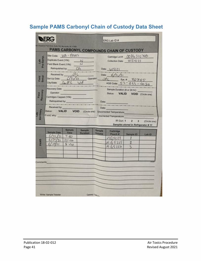
Sample PAMS Carbonyl Chain of Custody Data Sheet
Publication 18-02-012 Air Toxics Procedure Page 42 Revised August 2021
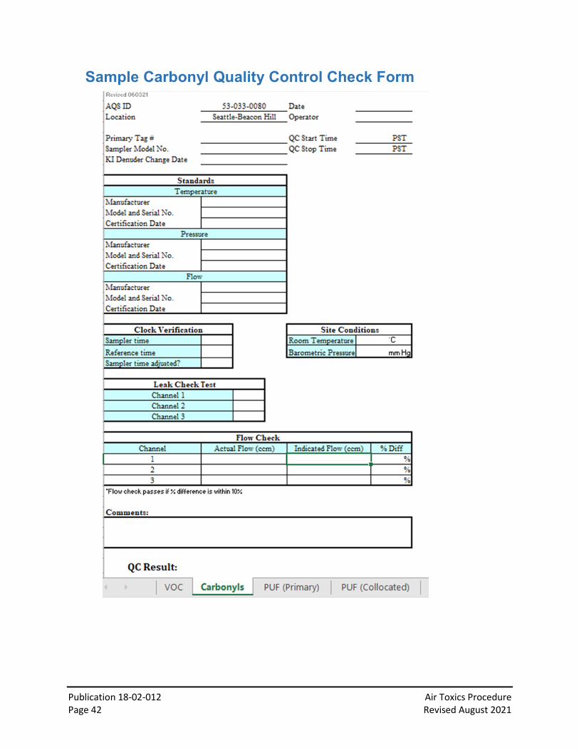
Sample Carbonyl Quality Control Check Form
Publication 18-02-012 Air Toxics Procedure Page 43 Revised August 2021
Sample PAH Chain of Custody Data Sheet

Publication 18-02-012 Air Toxics Procedure Page 44 Revised August 2021
Sample PAH Quality Control Check Form

Publication 18-02-012 Air Toxics Procedure Page 45 Revised August 2021
Sample PM10 Metals Quality Control Check Form