aircheck kit k8573nb sampling instructions v8
TRANSCRIPT

Use the personalized cover page from your AirCheck Notebook with this revised set of instructions.We will include a hard copy of these instructions with your next order.
™Aircheck Notebook™for Aircheck Kit K8573NB
TRACE AnalyticsLLC™the AirCheck Lab
15768 Hamilton Pool Rd. Austin, TX 78738 • (p) 512-263-0000 • (f) 512-263-0002 • www.AirCheckLab.com
Tr a i n i n g V i d e o s A v a i l a b l e O n l i n e !www.AirCheckLab.com

Cover Page...................................................................................................................... iTable of Contents .......................................................................................................... ii
Section 1 - AirCheck Kit™ K8573NB Sampling Instructions Parts List............................................................................................................1-1 Introduction .......................................................................................................1-2 Step 1 - Preparation........................................................................................1-3 Step 2 - Pre-Assembly of Sampling Equipment .......................................1-3 ISO 8573-1 Purity Classes Explained .........................................................1-4 Step 3 - Begin Filter Test ...............................................................................1-4 Step 4 - Begin Water Vapor Test ..................................................................1-7 Step 5 - Begin Oil Vapor Test ......................................................................1-10 Step 6 - Conclude Filter Test.......................................................................1-11 Step 7 - Prepare Field Blanks .....................................................................1-12 Step 8 - Review Data Sheet, Return Sample ...........................................1-12
Section 2 - Kit Cleaning & Maintenance Kit Cleaning Instructions ................................................................................2-1 Flowmeter Care ................................................................................................2-1 Tube Holder Inspection ...................................................................................2-1
Section 3 - Frequently Asked Questions .............................................................3-1
Section 4 - Technical Documents Example Data Sheet........................................................................................4-1 ISO 8573 White Paper....................................................................................4-2
Table of Contents
TRACE AnalyticsLLCKit K8573NB » Table of Contents
©2013 Trace Analytics, LLC. All rights reserved. • 800-247-1024 • www.AirCheckLab.com • [email protected]_V8 Revised 12/27/2013 Page ii

TRACE AnalyticsLLCKit K8573NB » Parts List
©2013 Trace Analytics, LLC. All rights reserved. • 800-247-1024 • www.AirCheckLab.com • [email protected]_V8 Revised 12/27/2013 Page 1-1
Parts List
These items are covered by the AirCheck Kit™ Lifetime Warranty. Trace Analytics will provide a free replacement for any non-working hardware item. The non-working item must be returned to receive free replacement. Warranty does not cover lost or contaminated items. Contact Customer Service for a Return Authorization Number.
Hardware (Covered by the AirCheck Kit Lifetime Warranty)
Please call or email us to request a quote for your restock. Sampling media varies depending on the type of analysis requested.
Consumables
Part No: F40001/4" NPT Adaptor, 20-50 psi
Part No: F40411/4" NPT Adaptor, 51-125 psi
Part No: C633Filter Flowmeter, 20-140 LPM
Part No: C655Tube Holder, 5/16”
Part No: C6 tTube Flowmeter, 1-5 LPM
Part No: VariesSampling Media
Part No: VariesField Blanks
Part No: C657Cleanser
Part No: C636cTip Breaker
Part No: C6343’ Tubing w/ 3/8” Adaptor
Part No: C667Spare Parts
Part No: C606Carrying Bag (rental only)
Part No: C656Tube Holder, 3/8”
Part No: CCarrying Case (purchase only)
Particle-free tubing and NIST-traceable flowmeters & timers are available for organizations that require them.
Optional Items Available for Purchase
Part No: CAL1Calibrated Flowmeters
Part No: CAL2Calibrated Timer
Part No: 85-H12Particle-Free Tubingw/ 1/4” Fittings

K8573NBRevision-Interim 17April2017
DocName:Table1a
desiccant** refrigerantTypeofSamplingMedia FilterCassette 5a/-Ptube 20a/-Ptube CharcoalTube
PurityClasses 1 2–3 4–6 1MinAirVolume,Liters 12,000 50 20 400
Minutes 120 12.5 5 100Flowrate 100 4 4 4
PurityClasses 2 2–3 4–6 2
MinAirVolume,Liters 1,200 50 20 40Minutes 24 12.5 5 10Flowrate 50 4 4 4
PurityClasses 3–5 2–3 4–6 3–4
MinAirVolume,Liters 500 50 20Minutes 10 12.5 5Flowrate 50 4 4
PurityClasses 6–7 2–3 4–6 3–4
MinAirVolume,Liters 250 50 20SamplingTime,Minutes 5 12.5 5
Flowrate,LPM 50 4 4Whensamplingforpartialanalysese.g.onlyforparticulatesoroilaerosols,seeSection1offullinstructions
Table1a:SamplingTimesforCompletePWOTestsbyAnalysisPackage,supercedestimesinK8573NB&NXInstructions
PleaseusethefollowingTable1atodeterminesamplingtimeswhenobtainingafullsamplethatincludesparticles,water,andoilaerosol&vapor(forProorDiagnostic)oroilaerosol(forValueandBasicpackages).
Notrequired
BASIC
VALUE
WATERVAPOR
Notrequired
PROOR
DIAGNOSTIC
ANALYSISPACKAGE
TYPEOFSAMPLE Particulate&OilAerosol* OILVAPOR*
*Formula-Ifunabletoachievepreferredflowrate,usetheminimumairvolumeanddivideitbyflowratefromLargeFlowmeter
AirVolume,LitersFlowRate,L/min(LPM)
=SamplingTime,min.
**Forwateronly:AirVolumeistheMaximumallowed.IfClass1required,refertoTable3a

TRACE AnalyticsLLCKit K8573NB » Introduction
©2013 Trace Analytics, LLC. All rights reserved. • 800-247-1024 • www.AirCheckLab.com • [email protected]_V8 Revised 12/27/2013 Page 1-2
IntroductionThe AirCheck Kit™ Model K8573NB is designed after ISO 8573 sampling protocols for collection of particles ≥0.5 microns, water vapor, and oil (aerosol and vapor) in compressed air. Refer to the White Paper in Section 4 for details on sampling and analytical methods that may vary from ISO 8573. Samples collected using this kit are sent to Trace Analytics’ analytical laboratory for analysis and reporting. The AirCheck Kit™ can be used for a variety of specifications other than ISO 8573. Contact Trace Analytics, LLC to discuss your specific requirements. Sampling media is customized per your air quality testing needs. Trace Analytics is an analytical chemistry laboratory accredited to ISO 17025 by A2LA. Visit www.AirCheckLab.com to view copies of our current accreditation documents as well as additional services and products available.
Trace Analytics will compare sample results with ISO Purity Class limits and classify your air test results as Pass or Fail. All AirCheck Reports™ are confidential and will only be discussed or e-mailed to authorized contacts on file with Trace Analytics.
Samples are analyzed and compared to ISO 8573-1 Purity Class Limits; see Table 1. You will select which Purity Classes your company requires prior to sampling. If you are taking a Baseline Test, the sample should be taken as if you are trying to meet the strictest Purity Class suitable for your company’s application. Class 1 for Particles and Oil require 100-120 minutes of sampling time. If your organization does not require the lower limits of Class 1 for Particles or Oil, select Class 2 air volumes & sampling times to conduct a Baseline Test.
Table 1 - ISO 8573-1:2010 Contaminants & Purity Classes
Sampling equipment should not be altered in any way that will disrupt the straight flow of the gas stream from the sampling outlet to the filter cassette. If a device is installed upstream of the filter cassette, any restriction should be at least 100 times the diameter of the largest particle expected. Valves and quick connects are frequently sources of high levels of particulate contamination.
Oil
By Mass Liquid Liquid, Aerosol, & VaporSee Note 2
0.10 – 0.5 µm 0.5 – 1.0 µm 1.0 – 5.0 µm mg/m3 °C °F g/m3 mg/m3
01 ≤ 20000 (3) ≤ 400 ≤ 10 - ≤ -70 ≤ -94 - < 0.012 ≤ 400000 (3) ≤ 6000 ≤ 100 - ≤ -40 ≤ -40 - < 0.13 - ≤ 90000 ≤ 1000 - ≤ -20 ≤ - 4 - < 14 - - ≤ 10000 - ≤ +3 ≤ +37 - ≤ 55 - - ≤ 100000 - ≤ +7 ≤ +45 - -6 - - - 0 - 5 ≤ +10 ≤ +50 - -7 - - - 5 - 10 - - ≤0.5 -8 - - - - - - 0.5 - 5 -9 - - - - - - 5 - 10 -X - - - > 10 - - > 10 > 5
Note 1:Note 2:
Note 3:
Class
ISO 8573 Oil includes aerosol, vapor and liquid oil. Liquid oil is typically sampled when wall flow is present, contamination is suspected, or results are greater than 5 mg/m3. Trace Analytics, LLC can provide a separate kit for liquid oil testing.For Particle Class 1 & 2 (0.1 - 0.5 µm range only), a laser particle counter is required. Rental of this equipment is available on a reservation basis.
Shaded areas indicate classes for which Trace Analytics methods apply. Others require techniques outside of Trace Analytics scope. See note 3.
As specified by the equipment user or supplier and more stringent than class 1
Particles WaterBy Particle Size
(maximum number of particles per m3 ) See Note 3Pressure Dewpoint

TRACE AnalyticsLLCKit K8573NB » Sampling Instructions
©2013 Trace Analytics, LLC. All rights reserved. • 800-247-1024 • www.AirCheckLab.com • [email protected]_V8 Revised 12/27/2013 Page 1-3
Step 1 – Preparation
Step 2 – Pre-Assembly of Sampling Equipment
1.1
• Purity Classes, Baseline or Other specification as appropriate. • Sampling times for all tests to be performed.• Pressure at sampling outlet.• NPT adaptor required, as based on outlet pressure. If outlet
pressure is 20-50 psig; use the unrestricted adaptor marked UNR, if outlet pressure is 51-125 psig; use adaptor marked 41.
• Type of dryer installed (Refrigerated or Desiccant).
Technician needs to know the following prior to sampling: 1.2
See Cleaning Procedure – Page 2-1• All fittings or adaptors shall be clean and free of oil, rust, or
particles.• Use only isopropyl alcohol or cleanser included in kit, NO
HYDROCARBON SOLVENTS.• Allow all parts and adaptors to dry fully prior to use.• Inspect Flowmeters: metal float must move easily & freely.• Inspect 3/8” and 5/16” Tube Holder, remove any glass
shards from previous tests.
Clean and Inspect Sampling Equipment
2.1• Attach center orifice of NPT adaptor (C) to 1-5 LPM Tube
Flowmeter (B). • Connect 5/16” Tube Holder (A) (for water vapor test) to top
of Tube Flowmeter (B).• Close needle valve (D) on Tube Flowmeter (B) by turning
clockwise. Do not overtighten.
A – 5/16” Tube Holder B – 1-5 LPM Tube FlowmeterC – NPT Adaptor Center OrificeD – Needle Valve
E – Flowmeter OutletF – Large FlowmeterG – 3/8” AdaptorH – Filter CassetteJ – Flowmeter Inlet
Pre-Assembly of NPT Adaptor and Small Flowmeter 2.2• Insert 3/8” female plastic adaptor (G) into one end of white
tubing. Thread adaptor onto the outlet side (black threads, labeled “FLOWMETER”) of the filter cassette (H). Connect tubing to barbed fitting at the Large Flowmeter Inlet (J).
• The Flowmeter Outlet (E) (upper orifice on back of Large Filter Flowmeter) must ALWAYS remain unplugged to vent air.
Pre-Assembly of Filter Cassette and Large Flowmeter
1.3• Ensure a clean, short, straight path – stainless steel fittings preferred, no rubber tubing.• If a valve is required for flow regulation, ensure that it is a stainless steel valve; seal material must not be composed of rubber or
other polymeric materials, except PTFE / Teflon™.• If PTFE / Teflon™ thread seal tape used, do not allow it to hang into air stream.
Prepare sampling point outlet with fittings to allow connection of AirCheck Kit’s 1/4" NPT female threaded adaptor

TRACE AnalyticsLLCKit K8573NB » Sampling Instructions
©2013 Trace Analytics, LLC. All rights reserved. • 800-247-1024 • www.AirCheckLab.com • [email protected]_V8 Revised 12/27/2013 Page 1-4
Step 3 – Begin Filter Test
Table 2: Particle & Oil Aerosol Flowrates
Both Oil Aerosols and Particles are collected on the Filter Cassette during the Filter Test.
3.1 If Sampling for Both Particles and Oil Aerosols:• Compare the air volume, flowrate, and sampling time for Particles and Oil Aerosol for your Purity Class from Table 2.• The air volumes, flowrates, and/or sampling times may be different for particles and oil. Always select the greater air volume and
its corresponding sample time. For example, if a sample is to be taken to meet ISO 8573-1:2010 [2:4:1] – Class 2 = Particles – 1,200 liters Minimum Air Volume, 100 LPM Flowrate, 12 minute Sample Time Class 4 = Water – Not used for this portion of the test Class 1 = Oil – 5,000 liters Minimum Air Volume, 100 LPM Flowrate, 50 minute Sample Time In this example, the filter cassette would need to be sampled for 5,000 liters minimum air volume; 50 minutes at 100 LPM.• If unable to obtain preferred flowrate, see formula in Table 2, below.
The designation of ISO 8573-1 Purity Classes specifies three major contaminants in compressed air – Particles, Water, and Oil.Purity Classes are designated as ISO 8573-1:2010 [P:W:O] where P = the purity class for particles (Classes 1 - 7, X) W = the purity class for water (Classes 1 - 9, X) O = the purity class for oil (Classes 1 - 4, X) For example, ISO 8573-1:2010 [2:4:1] indicates Class 2 for particles, Class 4 for water, and Class 1 for oil.When a class for any particular contaminant P, W, O is not specified, the designation is replaced by a hyphen. For example, ISO 8573-1:2010 [2: - :1] indicates that water will not be tested.
ISO 8573-1 Purity Classes Explained
Oil Conc. Minimum Preferred SampleLimit Air Volume Flowrate Time
0-1µm 1-5µm mg/m3 Liters L/min (LPM) MinutesParticles 400 ≤ 10 12,000 100 120
Oil Aerosol ≤ 0.01 5,000 100 50Particles 6,000 ≤ 100 1,200 100 12
Oil Aerosol ≤ 0.1 500 50 10Particles 90,000 ≤ 1,000 500 50 10
Oil Aerosol ≤ 1 250 25 10Particles - ≤ 10,000 500 50 10
Oil Aerosol ≤ 5 250 25 10Class 5 Particles - ≤ 100,000 500 50 10
If unable to achieve preferred flowrate, use the minimum air volume and divide it by the flowrate from the Large Flowmeter.
By Particle Size,max no. particles/m3
Class 1
Class 2
Class 3
Class 4
ISO 8573-1:2010
Air Volume, LFlow Rate, L/min (LPM)
= Sampling Time, min

Figure 2: Filter Cassette & NPT Adaptor
TRACE AnalyticsLLCKit K8573NB » Sampling Instructions
©2013 Trace Analytics, LLC. All rights reserved. • 800-247-1024 • www.AirCheckLab.com • [email protected]_V8 Revised 12/27/2013 Page 1-5
3.2• Select the appropriate Purity Class for Particles from Table 2• Calculate sampling time based on Air Volume and Flowrate• If unable to obtain preferred flowrate, see the formula from
Table 2 to calculate sampling time
If Sampling Only for Particles: 3.3• Select the appropriate Purity Class for Aerosols from Table 2• Calculate sampling time based on Air Volume and Flowrate• If unable to obtain preferred flowrate, see the formula from
Table 2 to calculate sampling time
If Sampling Only for Aerosols:
Figure 1: Data Sheet – System Information
• The total amount of time air flows through the filter must be recorded.• It is acceptable for the length of time to be more than listed in Table 2.
Filter Test continues through Water and Oil Vapor Tests.
A – Filter Cassette InletB – NPT Adaptor Outlet
3.4 Complete Section 4 of Data Sheet 3.6 Connect to Prepared Sampling Point3.5 Purge for 10 minutes• Check “Yes” if the correct classes are pre-printed. If “No,” enter classes under Particles, Water and/or Oil.• Provide all requested information
• Attach NPT Adaptor to sampling point.• Attach Filter Cassette Inlet (blue
threads, labeled “NPT”) (A) to NPT Adaptor Outlet, labeled "Attach Filter" (B). See Figure 2.
Open control valve at sampling point to allow air to flow from sampling outlet for 10 minutes.
4 System Information
Collection Point:
Other Reference:
TYPE OF PURIFICATION INSTALLED
SAMPLING POINT IDENTIFICATION:
SEND A REMINDER TO SAMPLE AGAIN:AnnualMonthly
QuarterlySemi-Annual
Other
Molecular Sieve/DesiccantRefrigerated DryerNo Dryer
No PurificationUnknown
PARTICLECL 1-7 or baseline
WATERCL 1-6 or baseline
OILCL 1-4 or baseline
ISO 8573-1:2010 [2:4:1]
USE AIR QUALITY SPECIFICATION ON FILE*
OTHER GASESMust Be Prearranged
Call Trace
Yes No
If "No", write purity classes below:
Other:
PROJECT/CLIENT NAME:

Figure 3: Air Flow Diagram
TRACE AnalyticsLLCKit K8573NB » Sampling Instructions
©2013 Trace Analytics, LLC. All rights reserved. • 800-247-1024 • www.AirCheckLab.com • [email protected]_V8 Revised 12/27/2013 Page 1-6
Figure 3: Data Sheet – Particles & Oil Aerosols
3.7 Begin sampling for Particles and/or Oil Aerosols• Open valve at sampling outlet and adjust to preferred flowrate from Table 2.• Begin timing test, write down the Filter Number, Flow Rate from Large Flowmeter, and Start Time on Filter Test Section of data
sheet. (See Figure 3, below.)• If you are unable to achieve the preferred flowrate, use the formula in Table 2 to determine the correct sampling time based on the
required air volume as noted in Table 2.• Consult the Flowmeter Reading Diagram to properly read the flowrate (see Figure 4, next page). If flowrate drops or varies, note
the variance(s) in the data sheet’s comment section.• The filter cassette remains in place during all tests. Stop Time and Total Time will recorded at the end of all tests in Step 6.
• Correct direction of air flow through all kit components is critical to the proper functioning of the AirCheck Kit.• Air must flow through the AirCheck Kit components in the following order: 1.) NPT Adaptor; 2.) Filter Cassette; 3.) White Tubing; 4.) Large Flowmeter.• The Flowmeter Outlet (at the top of the Large Flowmeter) must remain unobstructed.
Path of Air Flow through the AirCheck Kit
Sample Data
FILTER TEST (FILTER MUST BE RETURNED FOR ANALYSIS)WRITE "NOT APPLICABLE OR N/A" FOR EACH TEST NOT TAKEN
7
Filter Number:Flow Rate - (LARGE Flowmeter): LPM (between 20-140 LPM)
Clock Start Time: Stop Time:Total Sample Time: MINUTES : SECONDS:
Ambient Room Temperature:Ambient Barometric Pressure:
°F (68°F used as default)PSIA (14.7 PSIA used as default)

Type of Dryer Installed
ISO 8573-1:2010 Class
Tube Type Tube Scale Pressure Dewpoint, °C
Pressure Dewpoint, °F
Minimum AirVolume, Liters
Preferred Flowrate, LPM
Sample Time, Minutes
Class 1Class 2 5/a-P 5-200 ≤ -40 ≤-40 50 4 12.5Class 3 5/a-P 5-200 ≤ -20 ≤ -4 50 4 12.5Class 4 20/a-P 25-250 ≤ +3 ≤ +37 40 4 10Class 5 20/a-P 35-500 ≤ +7 ≤ +45 20 4 5Class 6 20/a-P 150-1500 ≤ +10 ≤ +50 10 4 2.5
Desiccant
Refrigerated
If unable to achieve preferred flowrate, use the minimum airvolume and divide it by the flowrate from the small Tube Flowmeter.
See Table 3a, below
TRACE AnalyticsLLCKit K8573NB » Sampling Instructions
©2013 Trace Analytics, LLC. All rights reserved. • 800-247-1024 • www.AirCheckLab.com • [email protected]_V8 Revised 12/27/2013 Page 1-7
Step 4 – Begin Water Vapor Test for Determining Pressure Dewpoint
4.1 Select the Appropriate Detector Tube, Determine Water Vapor Sampling TimeThere are two types of detector tubes:• 5/a-P for dew points common for desiccant dryers• 20/a-P for dew points common for refrigerated dryers
Selection of detector tube is based on the type of dryer installed on your compressed air system. If the dryer type is unknown, begin with the 5/a-P Detector Tube for Class 2. In some cases, you will use both tubes.
Determine sampling time from Table 3 either by the Purity Class your organization needs to meet or the type of water filtration installed. If you do not know either, then begin with the 5/a-P Detector Tube for Class 2.
If you are unable to reach a flowrate of 4 LPM, use the formula in Table 3 to determine the correct sampling time.
Figure 4: Flowmeter Reading Diagram
Table 3: Water Vapor Detector Tube Sample Volumes and Times
Immediately after starting the Filter Test, proceed to the Water Vapor Test. Tube tests are performed at the same time as the Filter Test.Water Vapor Test MUST be taken before the Oil Vapor Test. If you are not sampling for water vapor, skip to Step 5.
Note: Order of Testing
Air Volume, LFlow Rate, L/min (LPM)
= Sampling Time, min
Tube Flowmeter Filter Flowmeter
• Flowmeters must be level for proper reading.• Tube Flowmeter is read at the middle of the float.• Filter Flowmeter is read where the float changes
from straight sides to angled

TRACE AnalyticsLLCKit K8573NB » Sampling Instructions
©2013 Trace Analytics, LLC. All rights reserved. • 800-247-1024 • www.AirCheckLab.com • [email protected]_V8 Revised 12/27/2013 Page 1-8
Table 3a: Water Vapor Tube Sample Volumes for ISO 8573-1 Class 1
4.2 Check Flowmeter Tube Fitting 4.4 Close Control Valve4.3 Purge Small Flowmeter• Ensure that the 5/16” tube fitting is
installed on the tube flowmeter.• Close the control valve on the tube
flowmeter after 2 minutes.• Do not insert Detector Tube.• Open the flowmeter control valve
and allow air to flow for 2 minutes.
4.5Remove both tips of the Detector Tube by placing each tip in the small hole of the Tip Breaker and applying sideways pressure until the tip breaks off and falls inside the Tip Breaker.
Immediately insert the Detector Tube into the flowmeter fitting with arrow pointing up (num-bers will be upside-down) and tighten the fitting so that the Detector Tube is firmly seated.
Apply protective netting over the Detector Tube.
Break Tips & Insert Detector Tube
• Use caution when opening, inserting or removing Detector Tube – glass may splinter.
• Position Detector Tube and tip breaker over appropriate receptacle to capture any glass shards. Tip Breaker has ends capped to capture broken glass.
• Remove caps on Tip Breaker to dispose of glass appropriately.
WARNING - Danger of Injury Due to Sharp Edges
°C °F25 160 4050 280 7075 400 100100 480 120125 640 160
≤ -70°C dewpoint will be achieved if, and only if, the detector tube reading is ≤2.5. In other words, at any point in the test, should the detector tube reading exceed 2.5, the target dew point of ≤ -70°C will not be achieved.
Pressure Dewpoint Limit
≤ -94≤ -705-2005/a-P
Tube Type Tube Scale Pressure, psig
Minimum Air Volume, L
Preferred Flowrate, L/min
Sample Time, min
4

TRACE AnalyticsLLCKit K8573NB » Sampling Instructions
©2013 Trace Analytics, LLC. All rights reserved. • 800-247-1024 • www.AirCheckLab.com • [email protected]_V8 Revised 12/27/2013 Page 1-9
4.8At the end of the test time (or earlier if necessary) close the tube flowmeter valve and carefully remove the detec-tor tube.
Close the Tube Flowmeter Valve 4.10Record the Detector Tube Reading, Flow Rate, Sample Time, Sampling Point Pressure, and Scale on the Data Sheet.
Conclude the Water Vapor Test4.9Immediately determine a numerical value for the reddish/brown color change and note on the Data Sheet.Replace caps onto the detector tube.
Determine Results
If the 5/a-P tube was used AND reddish/brown color change reached the 200 mark, record results on data sheet and perform 2nd test using the 20/a-P tube. Repeat steps above.• If color change on the 5/a-P tube reads greater than 200 between 5.0 and 12.5 minutes, stop test and redo test using the 20/a-P tube. • If color change on the 5/a-P tube is between 100-150 for less than 5 minutes; use Class 4 sampling time with the 20/a-P tube.• If color change on the 5/a-P tube is greater than 150 for less than 5 minutes; use Class 5 sampling time with the 20/a-P tube.
Determining Correct Detector Tube and Sampling Time
4.6• Open control valve on flowmeter to obtain 4 LPM flowrate.• Begin timing test.
Begin the Water Vapor Test 4.7Watch the water vapor tube throughout the entire test for a reddish/brown color change.
Continuously Monitor the Detector Tube
If the reddish/brown color change is moving rapidly up the tube, be prepared to stop sampling and record the Detector Tube Reading and Sampling Time before the planned end of the test. Do not allow the color change to go past the upper line on the detector tube, or the Water Vapor Test will be invalid.
Note: In the Detector Tube picture shown above, the reading would be 125.
Watch Closely
Figure 4: Data Sheet – Water Vapor Detector TubeWATER VAPOR TEST TUBE(S) (MUST BE RETURNED)
Detector Tube Reading:
Flow Rate - (SMALL Flowmeter):Sample Time:
Sampling Point Pressure:
20/a-P Tube 5/a-P Tube
LPM (1-5)MIN : SECPSIG
0 - 1500
Scale used for 20/a-P Tube Only: (0-250), (0-500) or (0-1500)
: :

TRACE AnalyticsLLCKit K8573NB » Sampling Instructions
©2013 Trace Analytics, LLC. All rights reserved. • 800-247-1024 • www.AirCheckLab.com • [email protected]_V8 Revised 12/27/2013 Page 1-10
Table 4: Oil Vapor Sampling Flowrates
5.3• Remove the 5/16” tube fitting from
the tube flowmeter.• Install the 3/8” tube fitting.
Check Flowmeter Tube Fitting 5.5• Close the control valve on the tube
flowmeter after 2 minutes.
Close Control Valve
5.2• Record the Charcoal Tube ID onto
the Data Sheet.• See Figure 5, next page.
Record Charcoal Tube ID
5.4• Do not insert Charcoal Tube.• Open the flowmeter control valve
and allow air to flow for 2 minutes.
Purge Small Flowmeter
5.1• The Charcoal Tube is used for capturing oil vapors.• The tube must be returned to the laboratory for analysis.• Determine the sampling time based on Purity Class or Concentration Limit for
your particular operation. See Table 4, below.
Determine Sampling Time for Oil Vapor Test
Step 5 – Begin Oil Vapor TestThis test is required per ISO 8573-1 to report Total Oil Content for Oil Purity Class 1 and 2 only.If you are not sampling for oil vapor, skip to Step 6.
4.5Remove both tips of the Charcoal Tube by placing each tip in the large hole of the Tip Breaker and applying sideways pressure until the tip breaks off and falls inside the Tip Breaker.
Immediately insert the Charcoal Tube into the flowmeter fitting with arrow pointing up and tighten the fitting so that the Charcoal Tube is firmly seated. Apply protective netting over the Charcoal Tube.
Break Tips & Insert Charcoal Tube• Use caution when opening, inserting or removing
Charcoal Tube – glass may splinter.• Position Detector Tube and tip breaker over appropriate
receptacle to capture any glass shards. Tip Breaker has ends capped to capture broken glass.
• Remove caps on Tip Breaker to dispose of glass appro-priately.
WARNING - Danger of Injury Due to Sharp Edges
ISO 8573-1: 2010 Purity Class
Conc. Limit, mg/m3
Min. Air Volume, Liters
Preferred Flowrate, LPM
Sample Time, Minutes
Class 1 ≤ 0.01 400 4.0 100Class 2 ≤ 0.1 40Class 3 ≤ 1.0 40Class 4 ≤ 3.0 40
4.0 10
TRACE AnalyticsLLCKit K8573NB » Sampling Instructions
©2013 Trace Analytics, LLC. All rights reserved. • 800-247-1024 • www.AirCheckLab.com • [email protected]_V8 Revised 12/27/2013 Page 1-11
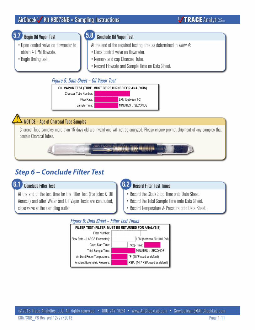
Figure 5: Data Sheet – Oil Vapor Test
Figure 6: Data Sheet – Filter Test Times
5.7• Open control valve on flowmeter to
obtain 4 LPM flowrate.• Begin timing test.
Begin Oil Vapor Test 5.8At the end of the required testing time as determined in Table 4:• Close control valve on flowmeter.• Remove and cap Charcoal Tube.• Record Flowrate and Sample Time on Data Sheet.
Conclude Oil Vapor Test
6.1At the end of the test time for the Filter Test (Particles & Oil Aerosol) and after Water and Oil Vapor Tests are concluded, close valve at the sampling outlet.
Conclude Filter Test 6.2• Record the Clock Stop Time onto Data Sheet.• Record the Total Sample Time onto Data Sheet.• Record Temperature & Pressure onto Data Sheet.
Record Filter Test Times
Step 6 – Conclude Filter Test
Charcoal Tube samples more than 15 days old are invalid and will not be analyzed. Please ensure prompt shipment of any samples that contain Charcoal Tubes.
NOTICE – Age of Charcoal Tube Samples
FILTER TEST (FILTER MUST BE RETURNED FOR ANALYSIS)Filter Number:
Flow Rate - (LARGE Flowmeter): LPM (between 20-140 LPM)Clock Start Time: Stop Time:
Total Sample Time: MINUTES : SECONDS:Ambient Room Temperature:
Ambient Barometric Pressure:°F (68°F used as default)PSIA (14.7 PSIA used as default)
Charcoal Tube Number:Flow Rate: LPM (between 1-5)
Sample Time: MINUTES : SECONDS
OIL VAPOR TEST (TUBE MUST BE RETURNED FOR ANALYSIS)
:

TRACE AnalyticsLLCKit K8573NB » Sampling Instructions
©2013 Trace Analytics, LLC. All rights reserved. • 800-247-1024 • www.AirCheckLab.com • [email protected]_V8 Revised 12/27/2013 Page 1-12
7.1 •
•
Prepare Field Blank
• If a sample is stopped or aborted, mark it as VOID, and restart with new set of sampling media.• Return any voided sampling media to Trace Analytics.• Blue filter cassettes are reusable; if cassettes are lost or not returned, a replacement fee will be billed.
Sampling Media May Only Be Used Once
• Samples requiring RUSH (one business day) analyses should be shipped via an expedited delivery method such as UPS, DHL, or FedEx to arrive no later than 10:30 AM. In some cases, Early A.M. delivery may be required to accommodate all RUSH samples.
• U.S. Postal Service is not a suitable delivery method for RUSH samples.• It is critical to contact Trace Analytics at least one day prior to delivery to pre-schedule all RUSH samples. We will notify you if we have not
received your samples by the anticipated time.
RUSH Samples
• Never expose Field Blanks to any compressed air or gas.• The laboratory uses Field Blanks as a quality control procedure to
determine if contamination occurred during handling or transport.• Use one set of Field Blanks per sampling batch. Sampling
batch size is to be determined by end user.• Common practice is 1 set of Field Blanks per day of sampling.
Important Notice – Field Blanks
7.1Confirm that ALL information is completed on the Data Sheet.See Example Data Sheet, page 4-1.
Review Data Sheet 7.2Repackage each sample with its respective Data Sheet and prepare all samples and blanks for shipping back to the lab.
Return Sampling Media and Data Sheets for Analysis
Step 8 – Review Data Sheet, Return Sample
Step 7 – Prepare Field Blanks
Important Notices
Figure 7: Data Sheet – Field Blanks
Tube Blank NumberCHARCOAL TUBE BLANK
8 Field Blank

TRACE AnalyticsLLCKit K8573NB » Kit Cleaning & Maintenance
©2013 Trace Analytics, LLC. All rights reserved. • 800-247-1024 • www.AirCheckLab.com • [email protected]_V8 Revised 12/27/2013 Page 2-1
Section 2 – Kit Cleaning & Maintenance
1. Place the adaptor in provided reclosable clear bag or other suitable container.2. Add apx. 20 drops of the provided Luminox® Low-Foaming Neutral Cleaner.3. Add warm tap water until the bag is approximately 2/3 full.4. Seal the bag, hold adaptor through bag walls and gently agitate until all of the
cleaner is dissolved. Do not shake bag without holding adaptor. Adaptor’s sharp corners can puncture bag.
5. Agitate for one additional minute.6. Empty bag into an appropriate sink.7. Rinse the adaptor in the bag under warm running water until all traces of the
cleaner have disappeared.8. Using the bag as a glove, turn the bag inside out while holding onto the adaptor
through the bag wall.9. Rinse the adaptor with isopropanol until all traces of water are removed. (Isopropa-
nol not provided.)10. Shake the liquid from the adaptor and allow to dry; it is now ready for use.
NOTE: Luminox cleaner and isopropanol do not interfere with ISO 8573-1 contami-nants determination. Adaptors may also be cleaned in ultrasonic bath or other method. Do not clean with solvents such as acetone, hexane, etc. that can interfere with GCMS analysis.
Flow Meter CarePrior to using the flow meter, check that it is operational:• Invert the flow meter and observe the float; it must travel freely throughout the scale.• If the float remains at the low end of the range, tap the flow meter to free it.• If the float sticks at that or any other point, contact Trace for cleaning instructions or a replacement, as needed.
Tube Holder InspectionInspect 3/8” and 5/16” Tube Holder, remove any glass shards from previous tests.
Kit Cleaning InstructionsINSPECT and CLEAN all parts to avoid sampling problems or invalid tests. When there is reason to believe that adaptors or fittings may have been contaminated by aerosol (oil or particulate), the adaptors should be cleaned.
Add Cleaner
Agitate, Drain, and Rinse

TRACE AnalyticsLLCKit K8573NB » Frequently Asked Questions
©2013 Trace Analytics, LLC. All rights reserved. • 800-247-1024 • www.AirCheckLab.com • [email protected]_V8 Revised 12/27/2013 Page 3-1
Section 3 – Frequently Asked Questions1 – Equipment and Sampling Media1.1 Adaptors & Fittings 1.1.1 Why are there two NPT adaptors? The unrestricted “UNR” NPT adaptor is for low flows from 20-50 psig. The “41” NPT
adaptor is for flows 51-125 psig. Low pressure systems use a wide variety of male fittings (Schroeder, quick disconnect, etc.). You will need to obtain the appropriate male fitting to connect the AirCheck Kit’s 1/4” NPT female threaded adaptor to the sampling outlet. If you have trouble obtaining sufficient flow, contact Trace's Technical Department.
1.1.2 How do I connect the AirCheck Kit™ to my sampling port? The AirCheck Kit™ comes with a ¼“ NPT female adaptor. You will need to determine what type of fittings you have at your sampling port and purchase fittings to connect to the ¼“ NPT female adaptor provided in the kit. Trace recommends using only stainless steel, clean fittings. Keep the path from the sampling port to the NPT adaptor as short and straight as possible. Avoid elbows, T’s, and the use of any hose or tubing in front of the NPT adaptor. These recommendations are based on the need to ensure that the connection does not contami-nate the sample with particles, rust, oil, or water. If you must introduce hose or tubing, use tubing that is designed to be particle free and is hydrophobic.
If a hose is used in the manufacturing process that delivers air directly or indirectly to the product, we recommend performing all tests with the hose in place to have an accurate representation of the air being delivered to your product.
1.1.3 Can I install a control valve to regulate flow? Yes. If a device is installed upstream of the filter cassette, any restriction should be at least 100 times the diameter of the largest particle expected. This is to avoid restricting the flow of oil aerosol and particles. Valves and quick connects are frequently sources of high levels of particulate contamination. Do not install any device that requires the air stream to be altered from its straight path to the filter cassette.
1.2 Flowmeters 1.2.1 There is a hole at the top of the large Filter Flowmeter. Should something go there? No – do not attach any fittings or
devices to the Flowmeter Outlet. This outlet must remain unrestricted throughout all air sampling. 1.2.2 The float or ball inside the flowmeter is not moving. What should I do? Do not take the sample if the float is not moving
freely. An accurate reading must be provided to provide valid results. See Cleaning Procedures, Page 2-1 for troubleshoot-ing instructions. If you are unable to restore free, unrestricted movement to the ball or float, it may be stuck due to oil or water contamination inside the float pathway. The flowmeter may need to be returned to Trace Analytics for service.
1.2.3 Do I have to use a calibrated flowmeter? Refer to your company’s Standard Operating Procedures (SOPs). If required, calibrated flowmeters may be purchased from Trace. You may also send the included flowmeters out to your own calibra-tion laboratory. Trace’s rental kits can include calibrated flowmeters upon request.
1.3 Filters – Is the filter part of the test? Yes, the filter cassette includes 3 pre-weighed filter membranes and white support pad. The thin membrane captures oil aerosols and particulates in the air stream. A single cassette should be used per each sample. Filter cassettes must be returned for analysis.
1.4 Voided or Invalid Tests – I messed up a test, can I throw away the sampling media? No. Return all sampling media to Trace. Include a datasheet and mark it “VOID”. If the filter cassette is not returned, a replacement fee will be charged.
1.5 Field Blanks 1.5.1 What are Field Blanks? A Field Blank consists of a filter cassette and a charcoal tube. The lab analyzes all blanks as a
quality control procedure to determine if contamination has occurred during transport, handling, or sampling.
TRACE AnalyticsLLCKit K8573NB » Frequently Asked Questions
©2013 Trace Analytics, LLC. All rights reserved. • 800-247-1024 • www.AirCheckLab.com • [email protected]_V8 Revised 12/27/2013 Page 3-2
1.5.2 How many Field Blanks do I need to send in? We recommend submitting one Field Blank with each batch of samples taken on the same day. Your QC team can request other quantities based on your sampling protocols.
2 – Sampling2.1 Filters – Which way do I connect the cassette to the adaptor? Thread the numbered side of the cassette to the 1/4" NPT threads
on the adaptor which is labeled "Attach Filter."2.2 Detector and Charcoal Tubes 2.2.1 How do I break the tips on the tubes? Always exercise caution when breaking the tips, as the glass may splinter, and there
is danger of injury due to sharp edges. The Tube Breaker has two sizes of holes - use the small hole for detector tubes; use the large hole for charcoal tubes. Place tip into hole and apply sidewards pressure until tip breaks. You can also use a pocket knife to break the tips.
2.2.2 Why do I have to return the charcoal tube? The charcoal tube must be analyzed for oil vapor in our laboratory. CAUTION – tube contents are toxic. Do not swallow. Prevent skin or eye contact. Dispose of tubes as hazardous waste. Always recap tubes and return to Trace. The detector tube reading will be verified, then disposed of safely.
2.2.3 Which way should the arrow point during sampling? The arrow represents the flow of air. With the Tube Flowmeter upright, insert the tube with the arrow pointing up or away from the flowmeter.
2.2.4 What do I do if the water vapor tube starts turning red? It is important to stop the test before it passes the 200 line on the 5-a/P tube or the 1500 line on the 20-a/P tube. The color change indicates the presence of water. If using the 5-a/P, record the reading on the datasheet and take a 2nd test with the 20-a/P tube. If using the 20-a/P tube, record the reading on the datasheet, testing for water is complete.
2.2.5 There are 3 scales on the 20-a/P tube, which one do I use? The correct scale to use is dependent on the expected dew point. If you do not know the expected dew point, then it is extremely important that you watch the tube during sampling. You will have to be prepared to stop the test if the color changes rapidly and/or it reaches any of the upper lines before the 2.5/5.0/10.0 minutes associated with each dew point.
2.3 Sampling Times 2.3.1 What is a Baseline test? When an organization has not established purity limits and orders a Baseline test, Trace will
analyze the sample and compare the air quality results with ISO 8573 purity classes. In most cases, the AirCheck Report will state the purity class that the air meets.
2.3.2 How do I determine sampling times for a Baseline Test? Most organizations want to know how good their air is. So, most will want to sample for the best classes possible, for particles and oil that means Class 1 which is about a 2 hour sampling time. If your organization does not need to meet such strict limits, then select Class 2 sampling times.
Determining the sampling time for water is different because it is dependent on the type of water filtration installed. A compressed air system with a refrigerated dryer cannot meet Class 1 or 2. If you have a desiccant dryer installed, select Class 1 or 2. If you have a refrigerated dryer, then select Class 3, 4, or 5. This is all dependent on you knowing what dew point your particular filtration is supposed to provide. If you do not have this information, then begin with the 5-a/P tube for Class 2 sampling time. If the tube color reaches the 200 mark, you will need to take a second test using the 20-a/P tube. The sampling times will vary depending on how quickly the color change occurred. See Step 4 – Begin Water Vapor Test for Determining Pressure Dewpoint, page 1-7.
2.3.3 I am unsure about the sampling times for my test. Refer to Table 2: Particle & Oil Aerosol Flowrates, page 1-4 for instruc-tions on calculating sample times. There is also an instructional video online at AirCheckLab.com/AirCheck-Academy. If

TRACE AnalyticsLLCKit K8573NB » Frequently Asked Questions
©2013 Trace Analytics, LLC. All rights reserved. • 800-247-1024 • www.AirCheckLab.com • [email protected]_V8 Revised 12/27/2013 Page 3-3
questions still remain after reading the instructions and watching the video, contact customer service and we will be happy to assist you.
2.4 Flowmeter – What is the correct way to read the flowmeter? The flowmeter should be placed on level surface in vertical position and read at eye level. Read line closest to the float. Float on Filter Flowmeter is read where the sides of the float change from straight to angled; Tube Flowmeter is read at the middle of the float. See Figure 4, page 1-9.
Do not submit a sample with a reading less than lowest mark on flowmeter.2.5 Microbial Sampling – Can I use this equipment to gather microbial samples? Microbial sampling requires additional specialized
equipment. Contact Trace for information on microbial sampling equipment available for rental or purchase. 2.6 Data Sheets & Sample Return 2.6.3 Shelf Life – How long will the filter cassettes, charcoal tubes, and detector tubes last? Sampling media has a shelf life of
approximately 2 years. Expiration dates are stamped on each media set’s return box. Samples must be received in laboratory within 15 days of sampling date.
2.6.4 Data Sheet – How should the Data Sheet be completed? Refer to the examples in the instructions and video or contact Trace. All samples must be submitted with a data sheet. If information is incomplete, your sample results may be delayed.
2.6.5 Sample & Data Sheet Review – Why is this important? Many of the problems that can cause delays, errors, and frustration can be avoided by taking a couple of minutes to inspect equipment prior to sampling and after obtaining a sample. Inspect data sheet for missing information. Ensure that the data sheet is legible.
2.6.6 Sample Return – How do I return the sample? Will it be safe in the small box? Return all samples to Trace Analtyics - 15768 Hamilton Pool Rd., Austin TX 78738. If you need results in a hurry, please send the sample via UPS, Federal Express, or other traceable, expedited method. USPS Express Mail is not recommended for rush samples. UPS delivers next day shipments by 10:30 a.m. and Federal Express is no later than 10:00 a.m. We have received thousands of samples safely in the small boxes; however, occasionally, we do receive a sample that has been damaged. If a particular sample is of extreme importance and would cause great hardship to resample (as in the case of suspected contamination, or if your system is down pending results) then by all means, place the sample in a larger, sturdier shipping container.
2.6.7 Return Mailers – I can’t find the boxes to return my sample. Use any sturdy box. Boxes are provided with each shipment as a courtesy and convenience. If your return mailers are missing, unfortunately, we will have to bill for shipping & handling charges to replace them.
3 – Analysis3.1 Test Results – What are the samples analyzed for? A complete test includes particle size (0.5 µm or greater) and count, pressure
dew point, oil aerosol, and oil vapor.3.2 Detector Tube – Why do you include detector tubes for water? Water analysis by detector tube analysis is the only acceptable
method per ISO 8573. Other gases, such as sulfur dioxide and nitrogen oxides are also analyzed by detector tube. 3.3 Accreditation – Is Trace's laboratory accredited? Trace is an A2LA (American Association for Laboratory Accreditation) accredited
laboratory complying with ISO/IEC 17025. Accreditation documents are available at AirCheckLab.com/About-the-Labora-tory

TRACE AnalyticsLLCKit K8573NB » Frequently Asked Questions
©2013 Trace Analytics, LLC. All rights reserved. • 800-247-1024 • www.AirCheckLab.com • [email protected]_V8 Revised 12/27/2013 Page 3-4
4 – Routine Policies4.1 Standard Turnaround – ISO 8573 samples are analyzed within 5-7 days of receipt. Generally, reports are e-mailed by the end of
the day or the following day. Occasionally, due to high volume, equipment problems beyond our control, or holiday closures, samples may take longer.
4.2 Verbal Results – Trace does not provide verbal results. This policy is designed to protect you from receiving erroneous information.4.3 Rush Analyses – We can provide next-day analysis and reporting if scheduled prior to receipt at lab. A rush fee of $150 per
sample must be authorized. Occasionally, personnel may not be available, so please call to schedule any Rush Analyses. Rush samples should be sent via UPS, Federal Express, or other traceable, expedited method and scheduled to arrive no later than 10:30 a.m. UPS delivers next day shipments by 10:30 a.m. and Federal Express is no later than 10:00 a.m. USPS Express Mail is not recommended for rush samples, as Express/Priority Mail does not arrive early enough for us to provide rush service.
4.4 Freight – All shipments originate from our Austin, TX facility and are charged depending on size and weight of package plus a small handling fee. Other delivery methods such as Next Day, COD, certified, etc. are available at an additional cost.
4.5 Reminders – If you have a preferred testing schedule, such as monthly, quarterly, or annually; we will e-mail, fax or mail a message reminding you that your sample is due to be taken. Reminders are generally sent within the first 5 days of the month in which your sample is due. Date is determined from the last sample date. Past due reminders are also sent if sample is not received by month due.
4.6 Restocks – Contact our Service Team by phone or email to request a quote or place your restock request.4.7 Warranty & Money-Back Guarantee – The AirCheck Kit has a lifetime warranty and money-back guarantee. If any part of the
hardware fails to work properly, we will replace the non-working item at no cost. Contact Trace for a Return Authorization Number. If you are dissatisfied with the kit and/or our services, we will buy back the kit and any unused prepaid samples on a prorated basis. Warranty does not cover loss or contaminated items.
4.8 Authorized Contacts – Trace personnel will only discuss your air quality test results with Authorized Contacts on file. One contact is designated as Primary and other contacts will be listed as Alternates. It is critical to have current contact information for all contacts in the event we have urgent results to report. Reports will be e-mailed to contacts who have been designated by the Primary.

TRACE AnalyticsLLCKit K8573NB » Example Data Sheet
©2013 Trace Analytics, LLC. All rights reserved. • 800-247-1024 • www.AirCheckLab.com • [email protected]_V8 Revised 12/27/2013 Page 4-1
Section 4 – Technical Documents
1 Contact Information
4 System Information
5
6
Comments (continue on back if needed)
PLEASE NOTE
Sample Data
Rush Analysis Request
• Sample Shelf Life - Return to lab within 15 DAYS• Shelf Life - Sampling Media - See Exp Date on Return Box• AQ Spec/Other Gases - See Notebook FAQs 4.0 or call to schedule
MONTH DAY YEAR
Submittal of this air sample authorizes Trace Analytics, LLC to provide services. If purchase ordernumber is required by your company, please provide with sample. I attest that all informationprovided on this datasheet is truthful and accurate to the best of my knowledge.
PRINT Name (Person taking the test)
SIGNATURE
Collection Point:
Other Reference:
TYPE OF PURIFICATION INSTALLED
SAMPLING POINT IDENTIFICATION:
3 Purchase Order Information (if applicable)
PO Number: PO Valid Thru:
SEND A REMINDER TO SAMPLE AGAIN:
7
ISO AirCheck DataSheet™
Please check if you'd like the AirCheck Report sent to the person below (fill in information).
Contact E-mail
By marking this box, I understand that I am authorizing 1 Workday Analysis & Reporting for an additional $150 per sample. Initial here:
2 IMPORTANT: PLEASE CALL 1–800–247–1024 (ext. 2) or 1–512–263–0000 (ext. 2) TO SCHEDULE
RUSH
(555) 555-5555Mr. John Smith [email protected] (555) 555-5550
Mr. Joe BrownContact Phone FaxE-mail
Alternate (555) [email protected] (555) 555-5550Phone FaxE-mail
www.AirCheckLab.com
AnnualMonthly
QuarterlySemi-Annual
Other
Molecular Sieve/DesiccantRefrigerated DryerNo Dryer
No PurificationUnknown
USAXYZ Manufacturing26087Customer ID Customer Name Country
PARTICLECL 1-7 or baseline
WATERCL 1-6 or baseline
OILCL 1-4 or baseline
ISO 8573-1:2010 [2:4:1]
USE AIR QUALITY SPECIFICATION ON FILE*
OTHER GASESMust Be Prearranged
Call Trace
Yes No
If "No", write purity classes below:
Other:
7 Sampled By and Sample Date
CAREFULLY PRINT ALL INFORMATION AND RETURN A COPY WITH EACH SAMPLE SET. IF ANY OF THE PREPRINTED INFORMATION IN THE BOXES IS INCORRECT, MARK THROUGH AND CORRECT.
LG1001 12/31/14
15768 Hamilton Pool RoadAustin, Texas 78738800-AIR-1024 or 512-263-0000 • Fax: 512-263-0002E-mail: [email protected]
PROJECT/CLIENT NAME:
For Trace Use Only
FILTER TEST (FILTER MUST BE RETURNED FOR ANALYSIS)
Source Bottle Number:OTHER GAS TEST (BOTTLE MUST BE RETURNED FOR ANALYSIS)
WATER VAPOR TEST TUBE(S) (MUST BE RETURNED)
Charcoal Tube Number:Flow Rate: LPM (between 1-5)
Sample Time: MINUTES : SECONDS
OIL VAPOR TEST (TUBE MUST BE RETURNED FOR ANALYSIS)
Charcoal Tube Blank Number:
WRITE "NOT APPLICABLE OR N/A" FOR EACH TEST NOT TAKEN
-
Receiving I.D.
Receiver’s Initials
Filter Blank Number:FILTER BLANK - Uncap 1 sec, recap, 1/batch, no compressed air thru filter
Detector Tube Reading:
Flow Rate - (SMALL Flowmeter):Sample Time:
Sampling Point Pressure:
20/a-P Tube 5/a-P Tube
LPM (1-5)MIN : SECPSIG
0 - 1500
Scale used for 20/a-P Tube Only: (0-250), (0-500) or (0-1500)
NOX / SO2 TEST TUBE(S) (MUST BE RETURNED FOR ANALYSIS)NOX SO2
Detector Tube Reading:
0.2 LPM Flow Rate:Sample Time (5 min.):
LPMMIN : SEC
(0 - 25)
Scale used for SO2 Tube Only: (0-5) or (0-25)
(0 - 10)
Filter Number:Flow Rate - (LARGE Flowmeter): LPM (between 20-140 LPM)
Clock Start Time: Stop Time:Total Sample Time: MINUTES : SECONDS:
: :
For K8573NX Samples Only-
:
: :
Ambient Room Temperature:Ambient Barometric Pressure:
°F (68°F used as default)PSIA (14.7 PSIA used as default)
8 Field Blanks
CHARCOAL BLANK - break tips, recap, 1/batch, no compressed air thru tube
���� � � � � �
����� ���������
��;
;
50�����
�2SWLRQDO�
%$**(5
-2+1�60,7+
John Smith� � � � � �
����
� ��
�������
� � � � � �����
� � � � � �
� � � � � �
Example Data Sheet

TRACE AnalyticsLLCKit K8573NB » ISO 8573 White Paper
©2013 Trace Analytics, LLC. All rights reserved. • 800-247-1024 • www.AirCheckLab.com • [email protected]_V8 Revised 12/27/2013 Page 4-2
White Paper: ISO 8573 Compressed Air Contaminants, Purity Classes, & Methods
ISO 8573 on compressed air is comprised of nine documents that describe compressed air contaminants and purity classes plus the sampling and analytical techniques to be used. The standard is widely used in the instrument air, medical device, food, and pharmaceutical industries. A drawback of ISO 8573 is the complexity of sampling and the associated expense of re-plumbing the compressed air system to accommodate air quality testing. Trace Analytics has developed an approach that allows determination of compliance in a cost-effective and straightforward manner that does not compromise the quality of the results.
The performance of a compressed air system may be evaluated in terms of compressor output at the compressor itself, in the piping downstream of the compressor, and at the various points of use. Knowledge of the compressor output is important in terms of selecting downstream filtration and assessing gross contamination of the piping system. Trace Analytics provides the capability to extract a sample from the main air stream; however, experience has shown that users collect far more samples at points of use.
Choosing Purity Classes for Your ApplicationWe recommend that you purchase the set of ISO 8573 documents (available at www.iso.org or webstore.ansi.org for purchase and download) in order to fully understand the implications of complying with its requirements. Before adopting any classes for limits of contamination in your system, we recommend that you consider the requirements for your product and perform a baseline study. Adopting classes that are too stringent for your application is not only more expensive from the point of view of compressed air production, but forces you to meet those specifications even though they may far exceed your application’s requirements. Most users find that a hybrid standard in which portions of ISO 8573 are adopted is optimal for their application. Trace can customize an air specification based on your SOP requirements.
Sampling - Full Flow versus Partial FlowPartial flow sampling is used for aerosols (both solid and liquid) when you wish to know the concentration within a pipe and the sampling equipment does not have the capacity for the entire output of the compressor system. This requires insertion of a probe into the pipe and a correlation of linear flow rates between the system and sampling probe (this is termed isokinetic sampling). It is somewhat complex and time consuming and is generally used during an initial evaluation of the compressor system. NOTE: Partial flow sampling is inappropriate in systems where steady-state flow, temperature, and pressure cannot be maintained.
Full flow sampling may be used at any point in a compressed air system and requires a sampling device that has the capacity to handle the full flow at that point in the system. This accounts for the vast majority of samples, as most users wish to know the air purity at the point of use where air may come in direct or indirect contact with the product.
Sampling with Trace Analytics’ AirCheck Kit K8573™The AirCheck Kit Model K8573 series have been designed to perform either full flow sampling for point-of-use or partial flow sampling.
The full flow sampling kit consists of a stainless steel adapter to connect to the point being sampled, a flow-controlled outlet for oil vapor, water vapor, and specific gases, and a filter stack for collection of solid particles and oil aerosol.
The partial flow sampling kit adds a sampling probe and downstream filter flow controller. Trace Analytics’ sampling probe is curved (after EPA sampling specifications) where the one recommended by ISO 8573 is straight. Testing in our laboratory on 2 µm oil aerosol showed the two probes to be comparable. Trace Analytics’ partial sampling probe requires a 1/4” NPT thread in the pipe and the pipe must be > 2 inches in diameter. The flow in the pipe must be known so that the filter sampling rate can be adjusted to provide isokinetic sampling. The AirCheck Kit K8573 models can be readily adapted to collect any portion or all of the contaminants, and the microbial sampler KPSII collects microbiological contaminants.
Solid Particles are collected for microscopic examination on a filter as per ISO 8573. Trace Analytics’ method is not applicable for particle range 0.1 – 0.5 micron, which requires a direct-reading device such as a laser particle counter. Trace Analytics’ method is acceptable for ranges 0.5 – 1 and 1 – 5 of class 1 and 2 and classes 3-7 and X. For classes 6, 7 and X, which require a mass determination, the filter is extracted to remove oil and the concentration of particles by both size and mass are determined.
Water is comprised of vapor and liquid.
Water vapor is determined on-site with the use of a color-indicating detector tube as allowed by ISO 8573.

TRACE AnalyticsLLCKit K8573NB » ISO 8573 White Paper
©2013 Trace Analytics, LLC. All rights reserved. • 800-247-1024 • www.AirCheckLab.com • [email protected]_V8 Revised 12/27/2013 Page 4-3
Water liquid is determined by collecting water from a high efficiency coalescing filter, then the mass of water determined by measuring its volume in a graduated cylinder. At the user’s request, Trace Analytics will provide instructions on how to determine water liquid on-site in compliance with ISO 8573. User determined results can be included in Trace’s AirCheck Report if requested.
Oil is comprised of liquid, aerosol, and vapor components. Per ISO 8573, oil is defined as a mixture of hydrocarbons composed of six or more carbons.
Oil liquid as described in ISO 8573-2 must be measured on-site from a set of high efficiency coalescing filters. ISO sampling Method A may be used at any point in a compressed air system where heavy contamination levels of oil are believed to exist and for a contamination range from 1mg/m3 to 40 mg/m3. The testing time (50-200 hours) makes it unreasonable when numerous samples are required. Trace Analytics has developed an alternative sampling method that requires a sample time between 14 and 100 minutes depending on obtainable flow rate. Two high efficiency coalescing filters are used to collect liquid oil. The filters are returned to Trace’s lab extraction and gravimetric determination of the oil aerosol and oil liquid fractions of the sample. The sampling method is based on ISO 8573-2 Method A.
Oil aerosol is collected on a set of 3 filters in series as per ISO 8573. The inlet filter is also used for particle counting, thus saving time in sampling. In the laboratory, the pre-weighed filter is extracted and the difference between the weight after extraction and that before sampling is used to determine oil aerosol. ISO 8573 calls for analysis of the extract with infrared spectrometry. Trace’s alteration to the method drastically reduces the cost of analysis for oil aerosol. The Trace Analytics method has been verified to achieve >99.5% recovery for oil aerosol fortified filters. The sampling method is based on ISO 8573-2 Method B1.
Oil vapor is collected simultaneously with oil aerosol on a commercially available charcoal tube, rather than the special stainless steel tube called for in ISO 8573. Analysis is performed using gas chromatography-mass spectrometry as required by ISO 8573. Oil vapor is required for Classes 1 and 2 only.
Gases (carbon monoxide, carbon dioxide, sulfur dioxide, nitrogen dioxide, nitric oxide, and C1-C5 hydrocarbons) have no classes set by ISO 8573. They are collected in a gas sampling bag from which gases are determined by using color-indicating detector tubes on-site. As an alternative, Trace Analytics can perform analyses using gas chromatography from a glass vial for carbon monoxide, carbon dioxide, and C1-C5 hydrocarbons. Sulfur dioxide and nitrogen oxides can be determined on-site with the use of color-indicating detector tubes as allowed by ISO 8573.
Microbiological contaminants are required to be collected using a type of impaction tester that employs agar plate with culturable media. The samples are incubated and the surface visually examined to confirm the presence of viable, colony-forming microorganisms. No limits have been established by ISO 8573 to date. Sterilization of sampling equipment shall be performed with a suitable cleansing agent immediately before use. The Microbial Sampler KPSII will allow you to perform this type of analysis.
In ConclusionTrace Analytics’ AirCheck Kit K8573 and Microbial Sampler KPSII provide a cost-effective and convenient manner to comply with ISO 8573 purity classes. The few modifications made to the sampling and analytical techniques provide equivalent results at a fraction of the cost. In addition, you gain the expertise and credibility of a laboratory that has been accredited since 1991 and currently performs over 25,000 compressed air analyses each year.
White Paper Prepared by Richard A. Smith, CIH, Laboratory Director/Owner, Trace Analytics, LLC Updated 09 2012 For questions or comments, contact [email protected]