aircom dual commentator’s unit - pilote films · · 2012-08-31zähl elektronik-tontechnik •...
TRANSCRIPT
Rev. 4 08.10.2008 This document substitutes previous versions. page 1 of 28
Zähl Elektronik-Tontechnik • Odenthaler Str. 47 • D-51465 Bergisch Gladbach • [email protected] • www.zaehl.com
Distributor (National/International):
sono Studiotechnik GmbH • Haagerstraße 5 • D-81671 München • Tel. +49 89 419671-0 • [email protected] • www.sono.de
AIRCOM Manual
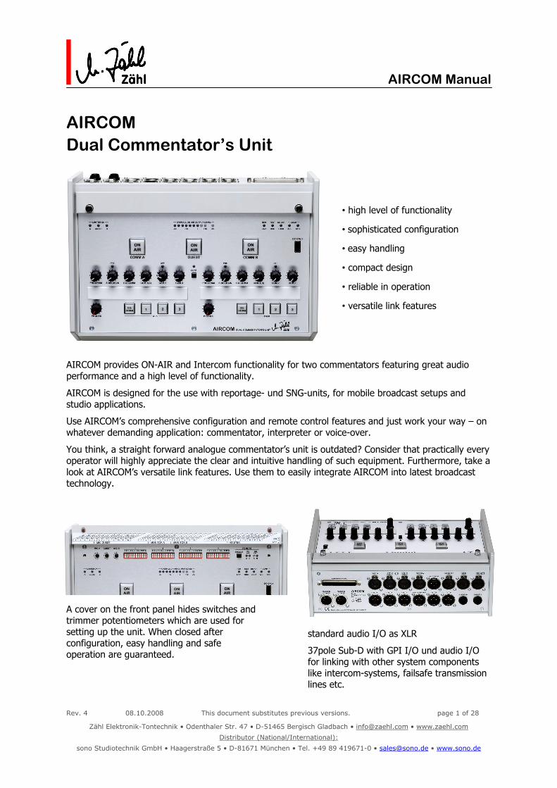
AIRCOM Dual Commentator’s Unit
• high level of functionality
• sophisticated configuration
• easy handling
• compact design
• reliable in operation
• versatile link features
AIRCOM provides ON-AIR and Intercom functionality for two commentators featuring great audio performance and a high level of functionality.
AIRCOM is designed for the use with reportage- und SNG-units, for mobile broadcast setups and studio applications.
Use AIRCOM’s comprehensive configuration and remote control features and just work your way – on whatever demanding application: commentator, interpreter or voice-over.
You think, a straight forward analogue commentator’s unit is outdated? Consider that practically every operator will highly appreciate the clear and intuitive handling of such equipment. Furthermore, take a look at AIRCOM’s versatile link features. Use them to easily integrate AIRCOM into latest broadcast technology.
A cover on the front panel hides switches and trimmer potentiometers which are used for setting up the unit. When closed after configuration, easy handling and safe operation are guaranteed.
standard audio I/O as XLR
37pole Sub-D with GPI I/O und audio I/O for linking with other system components like intercom-systems, failsafe transmission lines etc.

Rev. 4 08.10.2008 This document substitutes previous versions. page 2 of 28
Zähl Elektronik-Tontechnik • Odenthaler Str. 47 • D-51465 Bergisch Gladbach • [email protected] • www.zaehl.com
Distributor (National/International):
sono Studiotechnik GmbH • Haagerstraße 5 • D-81671 München • Tel. +49 89 419671-0 • [email protected] • www.sono.de
AIRCOM Manual

Rev. 4 08.10.2008 This document substitutes previous versions. page 3 of 28
Zähl Elektronik-Tontechnik • Odenthaler Str. 47 • D-51465 Bergisch Gladbach • [email protected] • www.zaehl.com
Distributor (National/International):
sono Studiotechnik GmbH • Haagerstraße 5 • D-81671 München • Tel. +49 89 419671-0 • [email protected] • www.sono.de
AIRCOM Manual
Contents 1. Important Notes and Safety Instructions................................................................. 4 2. Scope of Delivery ...................................................................................................... 5 3. Connection ................................................................................................................ 6 4. Front Panel Overview................................................................................................ 8 5. Basic Functions ......................................................................................................... 9
5.1. Configuration................................................................................................................................9 5.2. Commentator Channels A and B...................................................................................................10 5.3. Commentator/Interview Channel GUEST ......................................................................................12 5.4. Channels A+Guest+B Sum Output ...............................................................................................13 5.5. Level Meter und O/L-Display........................................................................................................13 5.6. Monitoring ..................................................................................................................................14
5.6.1. Internal Sources ....................................................................................................................................... 14 5.6.2. External Sources ...................................................................................................................................... 14 5.6.3. Intercom Call Signalisation ........................................................................................................................ 14 5.6.4. L-R Monitoring Options / Phones Output .................................................................................................... 15 5.6.5. CONFERENCE........................................................................................................................................... 15
6. Enhanced Function.................................................................................................. 16 6.1. On Air Lock.................................................................................................................................16 6.2. Guest To Idle A / Guest To Idle B ................................................................................................16 6.3. Aux Out Pre................................................................................................................................16 6.4. Conference Air Off ......................................................................................................................16 6.5. COM 1 A/B .................................................................................................................................17 6.6. COM 1 IF/B ................................................................................................................................17 6.7. COM 3 Signalisation Off...............................................................................................................17 6.8. Sidechain Pre..............................................................................................................................18 6.9. Link Program A / Link Program B .................................................................................................18 6.10. Test Oscillator.............................................................................................................................19
7. REMOTE................................................................................................................... 20 7.1. Audio I/O ...................................................................................................................................20 7.2. Operational Elements and Functional Displays ..............................................................................20 7.3. Control I/O - GPI I/O ..................................................................................................................21 7.4. Examples of Use .........................................................................................................................22
8. Connectors/Pin-Out................................................................................................ 24 9. Technical Data......................................................................................................... 26 10. Measures and Weights............................................................................................ 28
Rev. 4 08.10.2008 This document substitutes previous versions. page 4 of 28
Zähl Elektronik-Tontechnik • Odenthaler Str. 47 • D-51465 Bergisch Gladbach • [email protected] • www.zaehl.com
Distributor (National/International):
sono Studiotechnik GmbH • Haagerstraße 5 • D-81671 München • Tel. +49 89 419671-0 • [email protected] • www.sono.de
AIRCOM Manual
1. Important Notes and Safety Instructions
Before unpacking and operating the equipment read these Notes and Safety Instructions carefully. More notes and instructions can be found in the following chapters of this manual. Follow all notes and instructions. The term „equipment“ stands for the AIRCOM unit as well as the provided power supply.
1.1. The equipment must only be used for the purpose described in this manual.
1.2. Keep the manual for further reference. When passing the equipment on, enclose the manual.
1.3. Do not operate the equipment at - very high air humidity (>85% relative humidity) - high ambient temperature (>40°C) or in the vicinity of heat radiating equipment or objects - places which are exposed to solar radiation - at very low temperatures (<5°C)
1.4. Ensure appropriate air ventilation.
1.5. Do not block the ventilation slots of the equipment. Keep free a minimum of 20mm around the equipment.
1.6. Do not store the equipment at temperatures below -20°C or above +50°C.
1.7. Do never expose the equipment to environmental conditions which can lead to the incidence of condensation water.
1.8. Do not expose the equipment to mechanical stress or shock.
1.9. Ensure that liquids cannot get into the equipment.
1.10. Ensure that foreign objects cannot get into the equipment.
1.11. Only clean the equipment with smooth cleaning tissues and soft detergents.
1.12. Never open the equipment.
1.13. Only operate the unit with the provided power supply. When operating with other power supplies, warranty will be void.
1.14. In case the equipment has been dropped or there is any external or functional damage, do not continue to operate the equipment. Have the equipment checked at your dealer’s workshop or a person who is qualified to do such checks.
1.15. Only connect the equipment to a legally approved, earthed, mains power supply.
1.16. In case of any damage of mains cable or power supply there is the risk of a perilous electrical shock! Replace the mains cable immediately. Have the power supply checked or replace it. Regularly check mains cable and power supply for any damage.
1.17. When shipping use a package which protects the equipment from environmental impact such as mechanical shock or humidity.
1.18. The equipment applies to EU directives RoHS and WEEE. Disposal has to be carried out according to WEEE. As this equipment is classified as professional equipment for industrial use (B2B), manufacturer and purchaser conclude the following agreement: According to ElektroG §10 Abs. 2 Satz 3 (ref. to German/EU law) the manufacturer takes over the disposal if the purchaser sends back the equipment at his own expense. Alternatively the purchaser disposes of the equipment according to WEEE at his own expense. In case the purchaser passes on or sells the equipment, this agreement has to be passed on. Manufacturer WEEE register number: DE 90586269

Rev. 4 08.10.2008 This document substitutes previous versions. page 5 of 28
Zähl Elektronik-Tontechnik • Odenthaler Str. 47 • D-51465 Bergisch Gladbach • [email protected] • www.zaehl.com
Distributor (National/International):
sono Studiotechnik GmbH • Haagerstraße 5 • D-81671 München • Tel. +49 89 419671-0 • [email protected] • www.sono.de
AIRCOM Manual
1.19. Manufacturer’s warranty covers the equipment to be free from defects of quality at the time of delivery for a period of 24 month presumed that - the equipment was treated properly according to its intended use - all information and safety instructions given in this manual have been followed - the equipment shows no external damage - the equipment is shipped to the manufacturer or to an authorised repair-shop free of charge - a proof of purchase is supplied - a detailed failure description is supplied
The manufacturer takes over cost of parts and labour incurred by repair. Any other costs including shipping and packaging will be charged.
1.20. We expressly exclude any liability for incidental or consequential damages which might arise from operating the equipment, including failure of the equipment.
1.21. All information in this manual has been carefully reviewed. It has been updated at the time of passing for press. Nevertheless we do not take over any liability for sufficiency or errors.
1.22. EEC Declaration of Conformity: The equipment applies to applicable EMC rules 89/336/EEC.
2. Scope of Delivery
2.1. Unit AIRCOM
2.2. Power Supply
2.3. Mains Cable (not for all countries)
2.4. Manual
Rev. 4 08.10.2008 This document substitutes previous versions. page 6 of 28
Zähl Elektronik-Tontechnik • Odenthaler Str. 47 • D-51465 Bergisch Gladbach • [email protected] • www.zaehl.com
Distributor (National/International):
sono Studiotechnik GmbH • Haagerstraße 5 • D-81671 München • Tel. +49 89 419671-0 • [email protected] • www.sono.de
AIRCOM Manual
3. Connection
3.1. Power Supply 3.1.1. Plug the 4pole XLR connector which is mounted to the cable fixed to the power supply into one of the
4pole XLR connectors designated “POWER IN” on the rear panel of the AIRCOM unit.
3.1.2. Connect the power supply to a correctly earthed mains power socket. You may connect the power supply to 100-240VAC at 47-63Hz mains voltage without the need of selecting a voltage range.
Important Note: Always connect the power supply in the order described above. Otherwise there is a risk of damaging the power supply and/or the unit.
3.1.3. AIRCOM units provide two power inputs. You can connect two power supplies at the same time in order to ensure a fail-safe operation. If power at one of the inputs fails, the other one will take over.
3.1.4. 12V-24V regulated DC is allowed at the power inputs. We deliver power supplies within this voltage range. You can connect power supplies with differing voltages at the same time. The one with the higher voltage supplies the unit. If it fails, the one with the lower voltage will take over.
3.2. Audio 3.2.1. Microphone Inputs
Microphone inputs are designed for input levels from -64dBu to 0dBu (GUEST: -60dBu...-15dBu). Depending on the configuration setting the inputs provide 30V phantom power. Important Note: Before connecting a microphone always check if the input configuration on your AIRCOM complies with the microphone data. In case of incompatibility there is a risk of damaging your microphone.
3.2.2. Headphones Outputs
The headphones outputs deliver voltages up to 10Veff. Only connect headphones with an impedance of more than 30 Ohms per system. Please consider that the headphones output stages provide high gain margin in order to drive high impedance as well as low impedance headphones. Using low impedance headphones it is most unlikely that you need to set the PHONES volume controller to maximum position. Important Note: Always set the phones level potentiometer labelled „PHONES“ to minimum (fully counter-clockwise) before you connect your headphones. Otherwise there is a risk of damaging your ears by high sound pressure level. Furthermore there is a risk of damaging your headphones.
3.2.3. Other Audio Inputs and Audio Outputs
Standard audio inputs and audio outputs are transformer balanced and designed to a reference level of +6dBu and a maximum level of +18dBu (typ.). Auxiliary audio inputs and audio outputs are designed as electronically balanced stages at the same reference level and maximum level as above. Important Note: Connecting DC exceeding 1V is not allowed and can lead to damages inside the unit.

Rev. 4 08.10.2008 This document substitutes previous versions. page 7 of 28
Zähl Elektronik-Tontechnik • Odenthaler Str. 47 • D-51465 Bergisch Gladbach • [email protected] • www.zaehl.com
Distributor (National/International):
sono Studiotechnik GmbH • Haagerstraße 5 • D-81671 München • Tel. +49 89 419671-0 • [email protected] • www.sono.de
AIRCOM Manual
3.3. Control ports REMOTE GPI All control outputs are designed to be interfaced with 5V logic circuitry. Important Note: Connect DC in the 0-5V range to the control inputs only. Control outputs may only be connected to circuits which operate in the 0-5V DC range. Never connect any supply voltage directly to a control output. Refer to chapter „Technical Data“ to find information about maximum allowable current. Exceeding any limits can cause damage on the unit or the circuitry you connect. Refer to chapter „Technical Data“ for more details about circuitry and connection.
3.4. Lamp Supply/USB Right hand on the front panel there is a USB Type A socket designated “DC ONLY”. It serves exclusively for supplying a standard 5V LED Lamp with USB connector (commercially available with gooseneck). Important Note: Never connect any other equipment. Especially never connect a PC or PC peripheral equipment to this USB socket. There is the danger of damage to your AIRCOM as well as the connected equipment.
More details about technical data, functions and connector pin-outs are specified in the following chapters of this manual.

Rev. 4 08.10.2008 This document substitutes previous versions. page 8 of 28
Zähl Elektronik-Tontechnik • Odenthaler Str. 47 • D-51465 Bergisch Gladbach • [email protected] • www.zaehl.com
Distributor (National/International):
sono Studiotechnik GmbH • Haagerstraße 5 • D-81671 München • Tel. +49 89 419671-0 • [email protected] • www.sono.de
AIRCOM Manual
4. Front Panel Overview
Rev. 4 08.10.2008 This document substitutes previous versions. page 9 of 28
Zähl Elektronik-Tontechnik • Odenthaler Str. 47 • D-51465 Bergisch Gladbach • [email protected] • www.zaehl.com
Distributor (National/International):
sono Studiotechnik GmbH • Haagerstraße 5 • D-81671 München • Tel. +49 89 419671-0 • [email protected] • www.sono.de
AIRCOM Manual
5. Basic Functions This chapter is dedicated to basic functions only. When you work with AIRCOM for the first time, we recommend to study this chapter step by step. Before you start, please set all volume controls to minimum (counter-clockwise position). Enhanced functionality and comprehensive configuration are described in the following chapters.
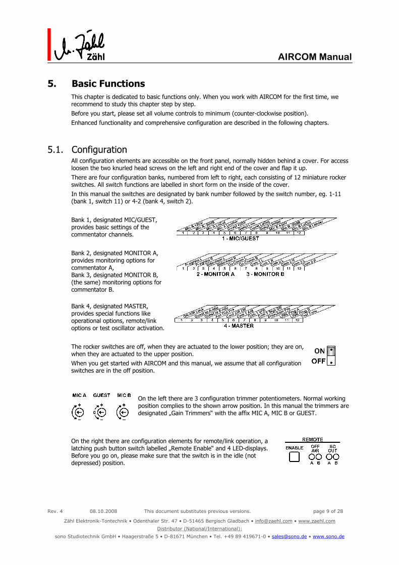
5.1. Configuration All configuration elements are accessible on the front panel, normally hidden behind a cover. For access loosen the two knurled head screws on the left and right end of the cover and flap it up. There are four configuration banks, numbered from left to right, each consisting of 12 miniature rocker switches. All switch functions are labelled in short form on the inside of the cover. In this manual the switches are designated by bank number followed by the switch number, eg. 1-11 (bank 1, switch 11) or 4-2 (bank 4, switch 2). Bank 1, designated MIC/GUEST, provides basic settings of the commentator channels. Bank 2, designated MONITOR A, provides monitoring options for commentator A, Bank 3, designated MONITOR B, (the same) monitoring options for commentator B. Bank 4, designated MASTER, provides special functions like operational options, remote/link options or test oscillator activation. The rocker switches are off, when they are actuated to the lower position; they are on, when they are actuated to the upper position. When you get started with AIRCOM and this manual, we assume that all configuration switches are in the off position.
On the left there are 3 configuration trimmer potentiometers. Normal working position complies to the shown arrow position. In this manual the trimmers are designated „Gain Trimmers“ with the affix MIC A, MIC B or GUEST.
On the right there are configuration elements for remote/link operation, a latching push button switch labelled „Remote Enable“ and 4 LED-displays. Before you go on, please make sure that the switch is in the idle (not depressed) position.

Rev. 4 08.10.2008 This document substitutes previous versions. page 10 of 28
Zähl Elektronik-Tontechnik • Odenthaler Str. 47 • D-51465 Bergisch Gladbach • [email protected] • www.zaehl.com
Distributor (National/International):
sono Studiotechnik GmbH • Haagerstraße 5 • D-81671 München • Tel. +49 89 419671-0 • [email protected] • www.sono.de
AIRCOM Manual
5.2. Commentator Channels A and B
5.2.1. Inputs and Configuration
Microphone inputs, XLR 3pole connectors labelled „MIC A“ and „MIC B“, are located on the rear panel.
Prior to connecting a microphone use configuration bank 1 in order to perform an input configuration appropriate to your microphone.
Setting a switch to the ON position will activate the described function.
Function MIC A MIC B
Phantom power +30V 1-1 1-9
- 20dB Pad 1-2 1-10
LoCut 80Hz 24dB/Oct. 1-3 1-11
Limiter 1-4 1-12
Phantom power: Only choose this option for microphones which are designed for operation
with 30V-phantom power. Otherwise there is a risk of damage to your microphone.
- 20dB Pad: Just in case you expect very high microphone levels. Also refer to section “Gain Setting” (see below).
LoCut 80Hz 24dB/Oct.: Frequencies below 80Hz are suppressed very effectively. Use depends on speaker, microphone and environmental conditions. LoCut will also reduce “pop noises” or low frequency interference caused by air condition systems.
Limiter: Output level is limited to reference level. If selected, a green LED (LIMITER ON) will light up on the front panel.
Note: Limiter configuration setting only affects the commentator channel outputs. Intercom outputs are always post limiter.
Gain Setting
Set microphone gain at the gain trimmers labelled “MIC A” and “MIC B” on the front panel, left hand in the configuration area. Always set gain with limiter off.
You can use the OVERALL ON AIR OUTPUT LEVEL to control your gain setting, if the respective ON AIR button is activated. The O/L (Overload) LED at the right end of the display lights up if there is the danger of signal clipping (1-2 dB below clipping), also refer to chapter 5.5.
In case your setting is fine with gain trimmer near its minimum (counter clockwise) and -20dB Pad OFF, please consider:
Best S/N ratio is assumed with this setting. But if you expect high unpredictable levels, i.e. you need maximum headroom, you should switch -20dB Pad to the ON position and on the other hand rise the gain setting.
Limiter function If a channel signal level exceeds reference level, the signal is controlled by the integrated limiter circuit at the output (As the limiter provides a soft-knee technique, in fact signals somewhat below reference level are controlled as well.). There is internal headroom of approximately 18dB before limiter.
Gain setting with Limiter
As described above, the limiter will to a certain amount affect levels below limiter threshold. If you set gain with limiter activated referring to the “0” LED on the level meter, you give away some headroom. So always set gain with limiter OFF, then switch it ON.

Rev. 4 08.10.2008 This document substitutes previous versions. page 11 of 28
Zähl Elektronik-Tontechnik • Odenthaler Str. 47 • D-51465 Bergisch Gladbach • [email protected] • www.zaehl.com
Distributor (National/International):
sono Studiotechnik GmbH • Haagerstraße 5 • D-81671 München • Tel. +49 89 419671-0 • [email protected] • www.sono.de
AIRCOM Manual
Please consider that a too high gain setting in combination with a limiter can lead to a loss of speech comprehensibility. E.g. background noise may be audible in speech intervals.
Note: Usually the limiter serves to suppress unattended high level peaks, which often occurs at on-site broadcast service. In case you use AIRCOM in a studio like environment, it might be more reasonable to switch off the limiter and leave the whole signal processing to a sound engineer on a mixing desk.
5.2.2. ON AIR Buttons and Channel A/B Outputs In basic configuration the ON AIR buttons are not active, when the unit is powered up. In this state they light up yellow. Push them once to activate, they light up red. Push them again to deactivate. Activating ON AIR button COMM A resp. COMM B switches the commentator’s microphone signals to the respective output. The outputs, 3pole XLR connectors, are located on the rear panel, designated OUT A and OUT B.
5.2.3. TALK buttons and Intercom Outputs TALK buttons have a „momentary“ switch action: They are active, as long as you keep them depressed. In the active state they light up red, in the deactivated state there is no lighting.
When a TALK button is active, ON AIR will be deactivated for the respective Commentator.
You can address four Intercom destinations:
Button 1: COM1 output, XLR 3pole connector on the rear panel designated COM1 OUT
Button 2: COM2 output, XLR 3pole connector on the rear panel designated COM2 OUT
Button 3: COM3 output, XLR 3pole connector on the rear panel designated COM3 OUT
Button CO-COMM: Co-Commentator on the same AIRCOM-Unit.
Note: As mentioned above, always post limiter signal is used for the Intercom outputs.
Rev. 4 08.10.2008 This document substitutes previous versions. page 12 of 28
Zähl Elektronik-Tontechnik • Odenthaler Str. 47 • D-51465 Bergisch Gladbach • [email protected] • www.zaehl.com
Distributor (National/International):
sono Studiotechnik GmbH • Haagerstraße 5 • D-81671 München • Tel. +49 89 419671-0 • [email protected] • www.sono.de
AIRCOM Manual
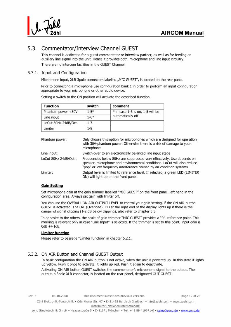
5.3. Commentator/Interview Channel GUEST This channel is dedicated for a guest commentator or interview partner, as well as for feeding an auxiliary line signal into the unit. Hence it provides both, microphone and line input circuitry. There are no intercom facilities in the GUEST Channel.
5.3.1. Input and Configuration
Microphone input, XLR 3pole connectors labelled „MIC GUEST“, is located on the rear panel.
Prior to connecting a microphone use configuration bank 1 in order to perform an input configuration appropriate to your microphone or other audio device.
Setting a switch to the ON position will activate the described function.
Function switch comment
Phantom power +30V 1-5*
Line input 1-6*
* in case 1-6 is on, 1-5 will be automatically off
LoCut 80Hz 24dB/Oct. 1-7
Limiter 1-8
Phantom power: Only choose this option for microphones which are designed for operation
with 30V-phantom power. Otherwise there is a risk of damage to your microphone.
Line input: Switch-over to an electronically balanced line input stage LoCut 80Hz 24dB/Oct.: Frequencies below 80Hz are suppressed very effectively. Use depends on
speaker, microphone and environmental conditions. LoCut will also reduce “pop” or low frequency interference caused by air condition systems.
Limiter: Output level is limited to reference level. If selected, a green LED (LIMITER ON) will light up on the front panel.
Gain Setting
Set microphone gain at the gain trimmer labelled “MIC GUEST” on the front panel, left hand in the configuration area. Always set gain with limiter off.
You can use the OVERALL ON AIR OUTPUT LEVEL to control your gain setting, if the ON AIR button GUEST is activated. The O/L (Overload) LED at the right end of the display lights up if there is the danger of signal clipping (1-2 dB below clipping), also refer to chapter 5.5.
In opposite to the others, the scale of gain trimmer “MIC GUEST” provides a “0”- reference point. This marking is relevant only in case “Line Input” is selected. If the trimmer is set to this point, input gain is 0dB +/-1dB.
Limiter function Please refer to passage “Limiter function” in chapter 5.2.1.
5.3.2. ON AIR Button and Channel GUEST Output In basic configuration the ON AIR button is not active, when the unit is powered up. In this state it lights up yellow. Push it once to activate, it lights up red. Push it again to deactivate. Activating ON AIR button GUEST switches the commentator’s microphone signal to the output. The output, a 3pole XLR connector, is located on the rear panel, designated OUT GUEST.

Rev. 4 08.10.2008 This document substitutes previous versions. page 13 of 28
Zähl Elektronik-Tontechnik • Odenthaler Str. 47 • D-51465 Bergisch Gladbach • [email protected] • www.zaehl.com
Distributor (National/International):
sono Studiotechnik GmbH • Haagerstraße 5 • D-81671 München • Tel. +49 89 419671-0 • [email protected] • www.sono.de
AIRCOM Manual
5.4. Channels A+Guest+B Sum Output The audio sum of channels A, B and GUEST (-3dB summing) can be helpful in cases which do not require single commentator output lines. The output, 3pole XLR, is located on the rear panel labelled OUT A+GUEST+B.
5.5. Level Meter und O/L-Display Level Meter The 9-LED display OVERALL ON AIR OUTPUT LEVEL with approximate PPM characteristic records all output signals post ON AIR button. It shows the peak level of the output with the highest level, not the summed output level. Note 1: When adjusting microphone gain you might use the level meter as a reference. As the meter is fed by post ON AIR button signal, just switch the respective channel ON AIR which you want to adjust. Note 2: For line checks you can switch the built in test oscillator on the outputs. The oscillator is applied straight to the output stage and will not be recorded by the level meter. Instead the level meter will show the microphone signal even when the oscillator is on. O/L- (Overload-) Display The bright red LED right hand of the level meter alerts you of high level overload. It will light up 1-2 dB below clipping level. Even very short overloads are displayed for at least one second, so you will not miss it. The circuitry records all three channels, A, B and Guest, post the input amplifiers. As with the level meter, only the highest level of the three is evaluated. The reason for using the post input amplifier signal is that level might be reduced by LoCut and Limiter. So evaluating the level at the output would not make sure that every overload is detected. Thus the overload display will light up even if the respective channel is not ON AIR active. Furthermore the circuitry evaluates if the limiter is on or off. As there is 6dB more headroom when the limiter is on, the LED will in this case light up at an input level 6 dB higher.

Rev. 4 08.10.2008 This document substitutes previous versions. page 14 of 28
Zähl Elektronik-Tontechnik • Odenthaler Str. 47 • D-51465 Bergisch Gladbach • [email protected] • www.zaehl.com
Distributor (National/International):
sono Studiotechnik GmbH • Haagerstraße 5 • D-81671 München • Tel. +49 89 419671-0 • [email protected] • www.sono.de
AIRCOM Manual
5.6. Monitoring Commentator A and B only, GUEST has no monitoring facilities. Each monitoring section provides 6 audio sources with individual level controls and a phones level control as a master. 4 sources are external: Program and Intercom inputs. 2 are internal: Local commentators A and B.
5.6.1. Internal Sources SIDECHAIN: The commentator’s own microphone signal pre limiter, i.e. channel A for commentator A and channel B for commentator B. The signal is present only, when a commentator is „active“ an output, i.e. if ON AIR button is active or a TALK button is depressed *.
CO-COMM: The co-commentator’s microphone signal pre limiter, i.e. channel B for commentator A and channel A for commentator B. The signal is present only, if the co-commentator is ON AIR or holds the CO-COMM intercom button depressed **.
* different behaviour if CONFERENCE is activated (refer to 5.6.5) or if SIDECHAIN PRE is on by configuration (refer to 6.8) * different behaviour if CONFERENCE is activated (refer to 5.6.5)
5.6.2. External Sources PROGRAM: Program signal, fed into 3pole XLR labelled PROGRAM on rear panel.
COM 1: Intercom signal, fed into 3pole XLR labelled COM1 on rear panel.
COM 2: Intercom signal, fed into 3pole XLR labelled COM2 on rear panel.
COM 3: Intercom signal, fed into 3pole XLR labelled COM3 on rear panel.
5.6.3. Intercom Call Signalisation Incoming audio signals at COM1, COM2 and COM3 are signalised at the respective TALK buttons 1, 2 and 3. Signalisation appears at commentator A and commentator B at the same time *. * different behaviour by configuration refer to 6.5 und 6.7 A TALK button lights up yellow, when the incoming signal level is higher than approx. -20dB. Signalisation is stored for approx. 8 seconds, so that even a short signal is clearly indicated. When a TALK button is depressed, signalisation will go off immediately. When a TALK button is depressed while there is an incoming signal triggering the signalisation, the TALK button lights up orange. In this case signalisation is not stored, thus the orange colour follows the incoming modulation. Basically the CO-COMM buttons provide the same signalling function, but they do not depend on audio modulation. They are triggered when the co-commentator presses his CO-COMM button. The signalisation is not stored, it is only active as long as the co-commentator holds his CO-COMM button depressed.

Rev. 4 08.10.2008 This document substitutes previous versions. page 15 of 28
Zähl Elektronik-Tontechnik • Odenthaler Str. 47 • D-51465 Bergisch Gladbach • [email protected] • www.zaehl.com
Distributor (National/International):
sono Studiotechnik GmbH • Haagerstraße 5 • D-81671 München • Tel. +49 89 419671-0 • [email protected] • www.sono.de
AIRCOM Manual
5.6.4. L-R Monitoring Options / Phones Output
Each monitoring source can be configured individually for commentator A or B to appear left, right or center at the phones output. Perform this setting at configuration banks 2 and 3. A record in the chart below stands for the respective switch in the ON position.
Commentator A
Commentator B
The monitoring mix is fed to the master level control labelled PHONES. Phones outputs are available on the rear panel as 6,3mm stereo jack sockets designated PHONES A and PHONES B. * differing behaviour if REMOTE/LINK is active, refer to 6.9
5.6.5. CONFERENCE
The CONFERENCE button (labelled CONF) and the associated LED are located on the front panel in between the monitor level controls of commentator A and commentator B.
After powering up the unit, CONFERENCE is not active. Push the button once to activate, push it again to deactivate.
When activated, the commentators can listen to their own microphone signal as well as their co-commentator’s microphone signal irrespective of any ON AIR or TALK function being active or not.
Example of use: During a show break the commentators can talk to each other without taking their headphones off (which could lead to missing important intercom messages).
Note: additional configuration: CONF AIR OFF Function, refer to 6.4
source left right center
Program 2-1 2-2 none* or both
Sidechain 2-3 2-4 none or both
Co-Comm 2-5 2-6 none or both
Com 1 2-7 2-8 none or both
Com 2 2-9 2-10 none or both
Com 3 2-11 2-12 none or both
source left right mittig
Program 3-1 3-2 none* or both
Sidechain 3-3 3-4 none or both
Co-Comm 3-5 3-6 none or both
Com 1 3-7 3-8 none or both
Com 2 3-9 3-10 none or both
Com 3 3-11 3-12 none or both
Rev. 4 08.10.2008 This document substitutes previous versions. page 16 of 28
Zähl Elektronik-Tontechnik • Odenthaler Str. 47 • D-51465 Bergisch Gladbach • [email protected] • www.zaehl.com
Distributor (National/International):
sono Studiotechnik GmbH • Haagerstraße 5 • D-81671 München • Tel. +49 89 419671-0 • [email protected] • www.sono.de
AIRCOM Manual
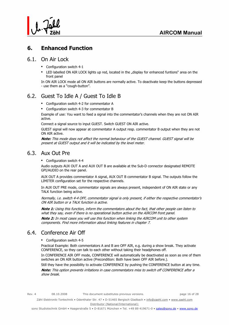
6. Enhanced Function
6.1. On Air Lock Configuration switch 4-1 LED labelled ON AIR LOCK lights up red, located in the „display for enhanced funtions“ area on the
front panel In ON AIR LOCK mode all ON AIR buttons are normally active. To deactivate keep the buttons depressed - use them as a “cough-button”.
6.2. Guest To Idle A / Guest To Idle B Configuration switch 4-2 for commentator A Configuration switch 4-3 for commentator B Example of use: You want to feed a signal into the commentator’s channels when they are not ON AIR active. Connect a signal source to input GUEST. Switch GUEST ON AIR active. GUEST signal will now appear at commentator A output resp. commentator B output when they are not ON AIR active. Note: This mode does not affect the normal behaviour of the GUEST channel. GUEST signal will be present at GUEST output and it will be indicated by the level meter.
6.3. Aux Out Pre Configuration switch 4-4 Audio outputs AUX OUT A and AUX OUT B are available at the Sub-D connector designated REMOTE GPI/AUDIO on the rear panel.
AUX OUT A provides commentator A signal, AUX OUT B commentator B signal. The outputs follow the LIMITER configuration set for the respective channels.
In AUX OUT PRE mode, commentator signals are always present, independent of ON AIR state or any TALK function being active.
Normally, i.e. switch 4-4 OFF, commentator signal is only present, if either the respective commentator’s ON AIR button or a TALK function is active.
Note 1: Using this function, inform the commentators about the fact, that other people can listen to what they say, even if there is no operational button active on the AIRCOM front panel. Note 2: In most cases you will use this function when linking the AIRCOM unit to other system components. Find more information about linking features in chapter 7.
6.4. Conference Air Off Configuration switch 4-5 Practical Example: Both commentators A and B are OFF AIR, e.g. during a show break. They activate CONFERENCE, so they can talk to each other without taking their headphones off. In CONFERENCE AIR OFF mode, CONFERENCE will automatically be deactivated as soon as one of them switches an ON AIR button active (Precondition: Both have been OFF AIR before.). Still they have the possibility to activate CONFERENCE by pushing the CONFERENCE button at any time. Note: This option prevents irritations in case commentators miss to switch off CONFERENCE after a show break.

Rev. 4 08.10.2008 This document substitutes previous versions. page 17 of 28
Zähl Elektronik-Tontechnik • Odenthaler Str. 47 • D-51465 Bergisch Gladbach • [email protected] • www.zaehl.com
Distributor (National/International):
sono Studiotechnik GmbH • Haagerstraße 5 • D-81671 München • Tel. +49 89 419671-0 • [email protected] • www.sono.de
AIRCOM Manual
6.5. COM 1 A/B Configuration switch 4-6 LED labelled COM1 A/B lights up yellow, located in the „display for enhanced funtions“ area on the
front panel COM1 switches to 2-channel mode on the input, while the output will work as usual. COM2 is deactivated completely. Commentators A and B can be addressed separately and signalisation on the TALK 1 buttons will also only light up at the respective commentator’s operation area. Pushing TALK 1 buttons will result in both commentators signals will appear as usual at COM1 output. The alternative labelling in brackets - front and rear panel - are intended for this mode: XLR input COM1 COM1A XLR input COM2 COM1B Level control COM1 in Commentator A operation area COM1A Level control COM1 in Commentator B operation area COM1B All operational controls for COM2 are deactivated which is signalled by the LEDs above the COM2 level controls. Both LEDs, labelled OFF, light up yellow. Signalisation at TALK 2 buttons is suppressed and the respective control outputs (GPI, refer to 7.3) are deactivated.
Feed an incoming intercom signal for commentator A to input COM1A and the respective signal for commentator B to input COM1B. COM1A signal will appear at the level control COM1A and will only be signalised at TALK 1 button of commentator A. COM1B signal will appear at the level control COM1B and will only be signalised at TALK 1 button of commentator B. COM3 is not affected by COM1 A/B mode.
6.6. COM 1 IF/B Configuration switch 4-7 LED labelled COM1 IF/B lights up green, located at the „display for enhanced funtions“ area on the
front panel In COM IF/B mode COM1 has priority in the monitor section. When there is audio modulation (same level threshold as implemented for signalisation) at COM1 input, all other monitor sources are dimmed by about 9dB. So any announcement on COM1 will be clearly emphasized. In case COM1 A/B is selected, COM1 IF/B will work independently on the A and B channel.
6.7. COM 3 Signalisation Off Configuration switch 4-8 In case you want to use COM3 as a second program input, signalisation at TALK 3 button would be disturbing. COM3 SIGNALISATION OFF mode suppressed signalisation at COM3 completely. All other functions of COM3 are not affected.
Rev. 4 08.10.2008 This document substitutes previous versions. page 18 of 28
Zähl Elektronik-Tontechnik • Odenthaler Str. 47 • D-51465 Bergisch Gladbach • [email protected] • www.zaehl.com
Distributor (National/International):
sono Studiotechnik GmbH • Haagerstraße 5 • D-81671 München • Tel. +49 89 419671-0 • [email protected] • www.sono.de
AIRCOM Manual
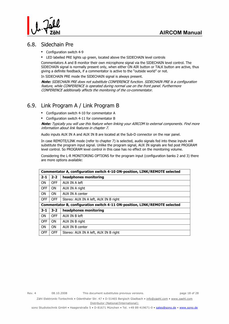
6.8. Sidechain Pre Configuration switch 4-9 LED labelled PRE lights up green, located above the SIDECHAIN level controls Commentators A and B monitor their own microphone signal via the SIDECHAIN level control. The SIDECHAIN signal is normally present only, when either ON AIR button or TALK button are active, thus giving a definite feedback, if a commentator is active to the “outside world” or not. In SIDECHAIN PRE mode the SIDECHAIN signal is always present. Note: SIDECHAIN PRE does not substitute CONFERENCE function. SIDECHAIN PRE is a configuration feature, while CONFERENCE is operated during normal use on the front panel. Furthermore CONFERENCE additionally affects the monitoring of the co-commentator.
6.9. Link Program A / Link Program B Configuration switch 4-10 for commentator A Configuration switch 4-11 for commentator B Note: Typically you will use this feature when linking your AIRCOM to external components. Find more information about link features in chapter 7.
Audio inputs AUX IN A and AUX IN B are located at the Sub-D connector on the rear panel.
In case REMOTE/LINK mode (refer to chapter 7) is selected, audio signals fed into these inputs will substitute the program input signal. Unlike the program signal, AUX IN signals are fed post PROGRAM level control. So PROGRAM level control in this case has no effect on the monitoring volume.
Considering the L-R MONITORING OPTIONS for the program input (configuration banks 2 and 3) there are more options available:
Commentator A, configuration switch 4-10 ON-position, LINK/REMOTE selected
2-1 2-2 headphones monitoring
ON OFF AUX IN A left
OFF ON AUX IN A right
ON ON AUX IN A center
OFF OFF Stereo: AUX IN A left, AUX IN B right
Commentator B, configuration switch 4-11 ON-position, LINK/REMOTE selected
3-1 3-2 headphones monitoring
ON OFF AUX IN B left
OFF ON AUX IN B right
ON ON AUX IN B center
OFF OFF Stereo: AUX IN A left, AUX IN B right
Rev. 4 08.10.2008 This document substitutes previous versions. page 19 of 28
Zähl Elektronik-Tontechnik • Odenthaler Str. 47 • D-51465 Bergisch Gladbach • [email protected] • www.zaehl.com
Distributor (National/International):
sono Studiotechnik GmbH • Haagerstraße 5 • D-81671 München • Tel. +49 89 419671-0 • [email protected] • www.sono.de
AIRCOM Manual
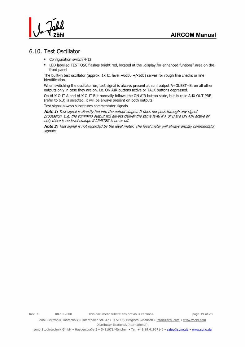
6.10. Test Oscillator Configuration switch 4-12 LED labelled TEST OSC flashes bright red, located at the „display for enhanced funtions“ area on the
front panel The built-in test oscillator (approx. 1kHz, level +6dBu +/-1dB) serves for rough line checks or line identification. When switching the oscillator on, test signal is always present at sum output A+GUEST+B, on all other outputs only in case they are on, i.e. ON AIR buttons active or TALK buttons depressed. On AUX OUT A and AUX OUT B it normally follows the ON AIR button state, but in case AUX OUT PRE (refer to 6.3) is selected, it will be always present on both outputs. Test signal always substitutes commentator signals. Note 1: Test signal is directly fed into the output stages. It does not pass through any signal procession. E.g. the summing output will always deliver the same level if A or B are ON AIR active or not; there is no level change if LIMITER is on or off. Note 2: Test signal is not recorded by the level meter. The level meter will always display commentator signals.

Rev. 4 08.10.2008 This document substitutes previous versions. page 20 of 28
Zähl Elektronik-Tontechnik • Odenthaler Str. 47 • D-51465 Bergisch Gladbach • [email protected] • www.zaehl.com
Distributor (National/International):
sono Studiotechnik GmbH • Haagerstraße 5 • D-81671 München • Tel. +49 89 419671-0 • [email protected] • www.sono.de
AIRCOM Manual
7. REMOTE
All I/Os for REMOTE LINK operation are provided at the Sub-D connector designated REMOTE GPI/AUDIO on the rear panel.
7.1. Audio I/O Also refer to chapter 6, configuration details AUX OUT PRE AUX OUT A, AUX OUT B AUX OUT A provides commentator A signal, AUX OUT B commentator B signal. Normally signals are present, when the respective commentator is active to the „outside world“, i.e. ON AIR button or TALK function is active. For alternative configuration refer to chapter 6.3. The AUX outputs always follow the LIMITER configuration of the main outputs.
AUX IN A, AUX IN B In case REMOTE LINK mode is activated, audio signals fed into these inputs will substitute the program monitor signal for the commentators. The AUX signals are fed post program level control, so the controller setting has no effect on the monitoring level. Find more configuration details in chapter 6.9.
Note: You can use AUX OUT A und AUX OUT B without activating REMOTE LINK mode or applying any control logic to your AIRCOM. E.g. you might easily use them to feed the commentator signals to an alternative transmission line. The use of AUX IN A and AUX IN B however requires REMOTE LINK mode and the use of control inputs, which are described in the following chapter.
7.2. Operational Elements and Functional Displays REMOTE ENABLE - latching pushbutton switch - located on the front panel, right part of the configuration area REM/LINK - yellow/red LED, located at the „display for enhanced functions“ area on the front panel
2 conditions have to be fulfilled in order to provide external control via control inputs: 1. REMOTE ENABLE switch is in the depressed position REM/LINK LED lights up yellow 2. control input LINK is activated REM/LINK LED changes its colour to red
AIRCOM REMOTE LINK mode is activated. Activating control input LINK without REMOTE ENABLE switch depressed does not produce any display nor any function.
OFF AIR A, OFF AIR B, SC CUT A, SC CUT B - red LEDs, green LEDs, located on the front panel, right part of the configuration area Since AIRCOM is in REMOTE LINK mode, the LEDs display the states of the control input with the same designation (refer to 7.3): OFF AIR LEDs light up red when the respective OFF AIR control inputs are activated, SC CUT light up green when the respective SC CUT control inputs are activated.
Note concerning REMOTE LINK: The dual guard when activating REMOTE LINK mode supports operational safety. In case there is faulty or irritating external control signal behaviour, you can deactivate REMOTE LINK mode by actuating the REMOTE ENABLE switch on the AIRCOM unit. Alternatively, do the same by removing the LINK control input signal. In case you do not want to use the external control option, just install an adequate jumper wire inside the Sub-D connector you use to mate the REMOTE GPI/AUDIO connector of your AIRCOM.

Rev. 4 08.10.2008 This document substitutes previous versions. page 21 of 28
Zähl Elektronik-Tontechnik • Odenthaler Str. 47 • D-51465 Bergisch Gladbach • [email protected] • www.zaehl.com
Distributor (National/International):
sono Studiotechnik GmbH • Haagerstraße 5 • D-81671 München • Tel. +49 89 419671-0 • [email protected] • www.sono.de
AIRCOM Manual
7.3. Control I/O - GPI I/O Outputs ON AIR A active, when ON AIR button COMM A is activated ON AIR B active, when ON AIR button COMM B is activated ON AIR G active, when ON AIR button GUEST is activated COM 1 A active, when TALK 1 button in operation area of commentator A is depressed COM 2 A active, when TALK 2 button in operation area of commentator A is depressed * COM 3 A active, when TALK 3 button in operation area of commentator A is depressed COM 1 B active, when TALK 1 button in operation area of commentator B is depressed COM 2 B active, when TALK 2 button in operation area of commentator B is depressed * COM 3 B active, when TALK 3 button in operation area of commentator B is depressed
* also refer to chapter 6.5 COM 1 A/B: In case COM1 A/B mode is configured, TALK 2 buttons are disabled. The same applies to COM2 control outputs. Inputs LINK when activated, sets AIRCOM into REMOTE LINK mode presumed REMOTE ENABLE switch is in the depressed position OFF AIR A when activated, ON AIR button COMM A will be deactivated * OFF AIR B when activated, ON AIR button COMM B will be deactivated * OFF AIR G when activated, ON AIR button GUEST will be deactivated * SC CUT A when activated, SIDECHAIN monitoring of commentator A is disabled * ** SC CUT B when activated, SIDECHAIN monitoring of commentator B is disabled * **
* applicable only if AIRCOM is in the REMOTE LINK mode ** CONFERENCE function overrides SC CUT, i.e. operator can use CONFERENCE even if SC CUT is activated. Note concerning OFF AIR: Use OFF AIR control inputs to control ON AIR state. Control input was designed as inverting control logic for the reason that the final decision, if they are ON AIR or not, should be reserved to the commentators. In order to prevent the operator error “commentator forgets to switch ON AIR” (e.g. after a show break) you can operate AIRCOM in ON AIR LOCK mode (refer to 6.1). Note concerning SC CUT: Practical examples for the use of SC CUT - In some applications program monitor signal contains the commentator’s signal during parts of the
program. In case digital transmission lines (which cause latency time) are used, there could be phase shifts between SIDECHAIN signal and program signal or even more irritating effects. Use SC CUT to remote control SIDECHAIN monitoring depending on the program signal which is fed to AIRCOM.
- For some commentators SIDECHAIN monitoring gives an important feedback about their ON AIR state. If not the commentator himself, but some other, off site personnel switches ON AIR/OFF AIR, use SC CUT to create the monitoring performance required for the application.

Rev. 4 08.10.2008 This document substitutes previous versions. page 22 of 28
Zähl Elektronik-Tontechnik • Odenthaler Str. 47 • D-51465 Bergisch Gladbach • [email protected] • www.zaehl.com
Distributor (National/International):
sono Studiotechnik GmbH • Haagerstraße 5 • D-81671 München • Tel. +49 89 419671-0 • [email protected] • www.sono.de
AIRCOM Manual
7.4. Examples of Use In the following example we presume that you use system components or intercom-systems with analogue audio I/Os and control I/Os with the required functionality - or even better, programmable functionality. The described applications are based on experiences that have been made by linking AIRCOM to a RIEDEL ARTIST system. This chapter is to be understood as a supplement to the straight functional description in chapters 7.1-7.3.
7.4.1. Simple Intercom Link Concept Commentator A and B signals are fed into the intercom-system. Intercom return signals for the commentators are fed into the AIRCOM monitoring section. Main operation is performed at the AIRCOM unit. The main intercom contact can be addressed by TALK 1 button on the AIRCOM unit. In order to address other intercom destinations, the commentators use the operating interface of the intercom-system. Note: In fact, more than one intercom destination can be linked between AIRCOM and intercom-system, depending on how many control I/Os there are available. AIRCOM Configuration 4-4 AUX OUT PRE 4-8 COM3 SIGNALISATION OFF 4-10 LINK PROGRAM A 4-11 LINK PROGRAM B 2-1, 2-2 monitoring option commentator A (differing setting possible, refer to 5.6.4 und 6.9) 3-1, 3-2 monitoring option commentator B (differing setting possible, refer to 5.6.4 und 6.9) REMOTE ENABLE in the depressed position Interconnections between AIRCOM and intercom-system AUX OUT A commentator A signal / analogue audio AUX OUT B commentator B signal / analogue audio AUX IN A intercom return signal 1 for commentator A / analogue audio AUX IN B intercom return signal 2 for commentator B / analogue audio COM 1 A control signal from AIRCOM to intercom-system COM 1 B control signal from AIRCOM to intercom-system OFF AIR A control signal from intercom-system to AIRCOM OFF AIR B control signal from intercom-system to AIRCOM LINK „always active“ control signal from intercom-system to AIRCOM or jumper wire inside Sub-D connector functional description - Via AUX OUT A and AUX OUT B commentator signals are fed into the intercom-system. Since
configuration switch 4-4 (AUX OUT PRE) is set, independent of ON AIR or TALK button states. - Inside the intercom-system commentator signals are handled depending on control signal states of
COM 1 A and COM 1 B. As a result the commentator signals are integrated into the intercom-system.
- As the commentator signals are always available (AUX OUT PRE is ON), they can be used for proprietary functions of the intercom-system (additional intercom channels).
Rev. 4 08.10.2008 This document substitutes previous versions. page 23 of 28
Zähl Elektronik-Tontechnik • Odenthaler Str. 47 • D-51465 Bergisch Gladbach • [email protected] • www.zaehl.com
Distributor (National/International):
sono Studiotechnik GmbH • Haagerstraße 5 • D-81671 München • Tel. +49 89 419671-0 • [email protected] • www.sono.de
AIRCOM Manual
- When a TALK button on the operating interface of the intercom-system is actuated, a control signal should drive the respective OFF AIR control input at the AIRCOM (This implements the same behaviour, as if a TALK button on the AIRCOM front panel is depressed.).
- Intercom return signals are fed via AUX IN A and AUX IN B into the AIRCOM monitoring section (Refer to settings of 4-10 and 4-11.).
- Since the AIRCOM „normal“ program input is not available in this configuration, program signal is connected to COM3 input. Signalisation at COM3 is disabled by setting of configuration switch 4-8 (COM3 Signalisation Off). … alternatively ... In case the intercom-system return signals do not just deliver intercom, but also include program monitor signals, COM3 input assignment is redundant. But consider the fact, that the level ratio in between intercom and program signals must then be well-balanced inside the intercom system, because it cannot be controlled by the commentator.
7.4.2. Intercom and Commentator Audio Link including fail-safe operation We presume, that you are well acquainted with the previously described „Simple Intercom Link“. In this example we describe an application with 2 commentators but no guest commentator.
Concept All settings and functionalities of the „Simple Intercom Link“ apply. But in addition, you use the intercom-system audio capacity fort he commentator’s ON AIR signals as well. Thus you use the infrastructure of the intercom-system and do not need to install separate audio lines. However, you may use the standard AIRCOM audio I/Os on a fail-safe system with redundant audio transmission. It takes over, if the intercom-system breaks down. E.g. connect sum output A+GUEST+B and PROGRAM input (maybe also COM3) to a failsafe-system. Note: Your commentators mainly use the clear AIRCOM operational interface and AIRCOM’s high quality audio front-end. At the same time you achieve a maximum utilisation of technical resources in the field … and there is an option for a failsafe-system. But consider: In this setup, your ON AIR signals rely mostly on the intercom-system. Make sure, that its audio capabilities meet your demands. In case of doubt … rather draw your ON AIR audio signals straight from the AIRCOM. AIRCOM Configuration refer to 7.4.1 Interconnections between AIRCOM and intercom-system like 7.4.1 but additionally ON AIR A control signal from AIRCOM to intercom-system ON AIR B control signal from AIRCOM to intercom-system LINK „always active“ control signal from intercom-system. It should release in case there is a functional problem or a system breakdown. functional description refer to 7.4.1 but additionally: - Inside the intercom-system commentator signals are handled depending on control signal states of
ON AIR A and ON AIR B. As a result they can be accurately routed inside the intercom-system and extracted at an adequate (studio) location.
- The intercom-system delivers intercom as well as program audio signals (same as 7.4.1 last passage „alternatively“)
- As we presume, that LINK will release in case the intercom-system breaks down, the AIRCOM PROGRAM monitor will automatically switch over to the XLR PROGRAM input.
- Optionally use SC CUT A/B (external disable of SIDECHAIN monitoring) in this setup. More information see chapter 7.3.

Rev. 4 08.10.2008 This document substitutes previous versions. page 24 of 28
Zähl Elektronik-Tontechnik • Odenthaler Str. 47 • D-51465 Bergisch Gladbach • [email protected] • www.zaehl.com
Distributor (National/International):
sono Studiotechnik GmbH • Haagerstraße 5 • D-81671 München • Tel. +49 89 419671-0 • [email protected] • www.sono.de
AIRCOM Manual
8. Connectors/Pin-Out
8.1. Audio-Inputs/Audio-Outputs
8.1.1. XLR sockets female 3pole, Inputs Pin 1 shield Pin 2 + / hot Pin 3 - / cold
8.1.2. XLR sockets male 3pole, Outputs Pin 1 shield Pin 2 + / hot Pin 3 - / cold
8.1.3. Jack Sockets Stereo 6,3mm, Phones Outputs Tip left signal Ring right signal Case Common / Ground
8.2. Power XLR socket male 4pole, Power In
Pin 1 Ground / Protective Earth Pin 2 Ground / Protective Earth Pin 3 0VDC Pin 4 +12V…+24VDC
8.1.1 – 8.1.2 8.1.38.2
8.3 refer to next page
Rev. 4 08.10.2008 This document substitutes previous versions. page 25 of 28
Zähl Elektronik-Tontechnik • Odenthaler Str. 47 • D-51465 Bergisch Gladbach • [email protected] • www.zaehl.com
Distributor (National/International):
sono Studiotechnik GmbH • Haagerstraße 5 • D-81671 München • Tel. +49 89 419671-0 • [email protected] • www.sono.de
AIRCOM Manual
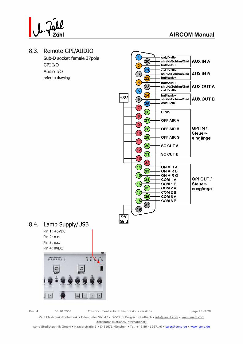
8.3. Remote GPI/AUDIO Sub-D socket female 37pole GPI I/O Audio I/O
refer to drawing
8.4. Lamp Supply/USB Pin 1: +5VDC Pin 2: n.c. Pin 3: n.c. Pin 4: 0VDC
Rev. 4 08.10.2008 This document substitutes previous versions. page 26 of 28
Zähl Elektronik-Tontechnik • Odenthaler Str. 47 • D-51465 Bergisch Gladbach • [email protected] • www.zaehl.com
Distributor (National/International):
sono Studiotechnik GmbH • Haagerstraße 5 • D-81671 München • Tel. +49 89 419671-0 • [email protected] • www.sono.de
AIRCOM Manual
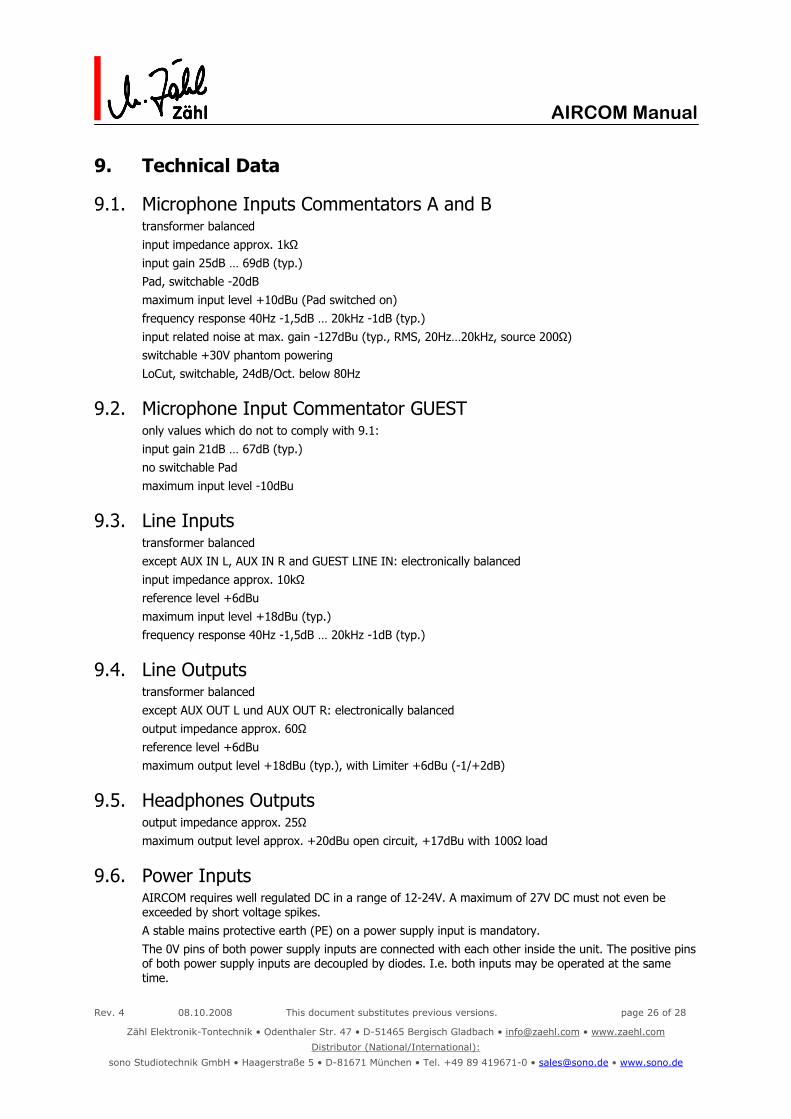
9. Technical Data
9.1. Microphone Inputs Commentators A and B transformer balanced input impedance approx. 1kΩ input gain 25dB … 69dB (typ.) Pad, switchable -20dB maximum input level +10dBu (Pad switched on) frequency response 40Hz -1,5dB … 20kHz -1dB (typ.) input related noise at max. gain -127dBu (typ., RMS, 20Hz…20kHz, source 200Ω) switchable +30V phantom powering LoCut, switchable, 24dB/Oct. below 80Hz
9.2. Microphone Input Commentator GUEST only values which do not to comply with 9.1: input gain 21dB … 67dB (typ.) no switchable Pad maximum input level -10dBu
9.3. Line Inputs transformer balanced except AUX IN L, AUX IN R and GUEST LINE IN: electronically balanced input impedance approx. 10kΩ reference level +6dBu maximum input level +18dBu (typ.) frequency response 40Hz -1,5dB … 20kHz -1dB (typ.)
9.4. Line Outputs transformer balanced except AUX OUT L und AUX OUT R: electronically balanced output impedance approx. 60Ω reference level +6dBu maximum output level +18dBu (typ.), with Limiter +6dBu (-1/+2dB)
9.5. Headphones Outputs output impedance approx. 25Ω maximum output level approx. +20dBu open circuit, +17dBu with 100Ω load
9.6. Power Inputs AIRCOM requires well regulated DC in a range of 12-24V. A maximum of 27V DC must not even be exceeded by short voltage spikes. A stable mains protective earth (PE) on a power supply input is mandatory. The 0V pins of both power supply inputs are connected with each other inside the unit. The positive pins of both power supply inputs are decoupled by diodes. I.e. both inputs may be operated at the same time.

Rev. 4 08.10.2008 This document substitutes previous versions. page 27 of 28
Zähl Elektronik-Tontechnik • Odenthaler Str. 47 • D-51465 Bergisch Gladbach • [email protected] • www.zaehl.com
Distributor (National/International):
sono Studiotechnik GmbH • Haagerstraße 5 • D-81671 München • Tel. +49 89 419671-0 • [email protected] • www.sono.de
AIRCOM Manual
If both power supplies deliver the same voltage, load is shared. If they deliver different voltages, the one with the higher voltage is loaded only. Power consumption is typically 15…30W, but for short periods of time this value may be exceeded substantially. The power supplies we deliver with AIRCOM have been selected to be capable for such operation. Hence we assume that the units are operated with these power supplies. In case AIRCOM is operated with other power supplies we do not guarantee for correct function of the units or any damage. Furthermore warranty will be void.
9.7. Control Outputs/GPI OUT Important: Follow all warnings and hints given in chapter 3.3 Control outputs are designed as „open collector“ circuitry. In the idle state they are high-impedance, but still connected to 5V by protective diodes. So never apply voltages higher than 5V. In the active state they interconnect to 0V. Do not exceed a maximum current of 80mA per output. A maximum of 400mA is allowed for all outputs together. You may supply relays and lamps directly from the 0V/5V pins of the REMOTE GPI/AUDIO connector. Consider that the overall maximum current must not exceed 250mA. When loading the unit’s 5V pins with 250mA, voltage will drop to approx. 4,3V. Functional Diagram
9.8. Control Inputs/GPI IN Important: Follow all warnings and hints given in chapter 3.3 All control inputs are designed as 5V logic circuitry. They are internally connected to 5V by a “pull-up” resistor. Connecting them to 0V or a voltage in the 0…1V range will activate them. Leaving an input open or connecting a voltage in the 4…5V range will leave it deactivated. Do not connect voltages which exceed the 0…5V range. You may supply relays and lamps directly from the 0V/5V pins of the REMOTE GPI/AUDIO connector. The same applies for the GPI OUT/REMOTE OUT and the MASTER GPI OUT connector. Consider that the overall maximum current must not exceed 250mA. When loading the unit’s 5V pins with 250mA, voltage will drop to approx. 4,3V.
9.9. Lamp Supply/USB Important: Follow all warnings and hints given in chapter 3.4 This output (designation “DC ONLY”) delivers 5 Volt DC nominal. It may be exclusively used for supplying a standard 5V LED Lamp with USB connector (commercially available with gooseneck). It may be loaded to a maximum current of 250mA, whereas the voltage will drop to approx. 4,3V. Never connect any active electronic components to this connector.

Rev. 4 08.10.2008 This document substitutes previous versions. page 28 of 28
Zähl Elektronik-Tontechnik • Odenthaler Str. 47 • D-51465 Bergisch Gladbach • [email protected] • www.zaehl.com
Distributor (National/International):
sono Studiotechnik GmbH • Haagerstraße 5 • D-81671 München • Tel. +49 89 419671-0 • [email protected] • www.sono.de
AIRCOM Manual
10. Measures and Weights
10.1. AIRCOM Unit enclosure plastic material desk console, EMC coated front panel / rear panel clear anodised aluminium overall measure W x H x D 295 mm x 110 mm x 215 mm height of front panel at front 43 mm height of front panel at rear 90 mm weight approx. 2,6 kg
10.2. Power Supply measure W x H x D 146 mm x 75 mm x 44 mm or 120 mm x 55 mm x 37 mm weight 0,6 kg or 0,4 kg length of fixed cable (DC to unit) approx. 1,6 m length of mains cable 1,5 m - 2,0 m
10.3. Delivery form cardboard box approx. 500 mm x 340 mm x 220 mm gross weight approx. 4,75 kg