air‐conditioning, heating and ventilation 8 building services 8‐76 vol. 3 additions, alterations...
TRANSCRIPT
Part 8 Building Services 8‐75
Chapter 2
AIR‐CONDITIONING, HEATING AND VENTILATION
2.1 GENERAL
2.1.1 Purpose
The purpose of this chapter is to provide minimum standards for regulating and controlling the design, construction, installation, quality of materials, location, operation, performance, maintenance and use of air conditioning, heating and ventilation systems to ensure acceptable conditions of air inside the building required for human health, safety and welfare with energy conservation.
2.2 Scope
2.2.1
The provisions of this Code shall apply to erection, installation, alteration, repair, relocation, replacement, addition to, use and maintenance of any air‐conditioning, heating and ventilation systems.
2.2.2
Additions, alterations, repairs and replacement of equipment or systems shall comply with the provisions for new equipment and systems except as otherwise provided in Sec 2.2.2.1.
2.2.3
Where, in any specific case, different sections of this Code specify different materials, methods of construction or other requirements, the most restrictive one shall govern. Where there is a conflict between a general requirement and a specific requirement, the specific requirement shall be applicable.
2.2.4
The regulations of this Code are not intended, and shall not be understood to permit violation of the provisions of other ordinances, regulations or official requirements in force.
2.3 Application
It shall be unlawful to install, extend, alter, repair or maintain air‐conditioning, heating and ventilation systems in or adjacent to buildings except in compliance with this Code.
2.3.1 Existing Systems
a) Existing Installations: Air‐conditioning, heating and ventilation systems in existence at the time of adoption of this Code may have their use, maintenance or repair continued if the use, maintenance or repair is in accordance with original design and location and no hazard to life, health or property has been created by such system.
b) Additions, Alterations or Repairs: Additions, alterations or repairs may be made to any air‐conditioning, heating or ventilation system without requiring the existing system to comply with all the requirements of this Code, provided the addition, alteration or repair conforms to the requirements of a new system.

Part 8 Building Services
8‐76 Vol. 3
Additions, alterations or repairs shall not make an existing system unsafe, create unhealthy or overloaded conditions.
c) Changes in Building Occupancy: Air‐conditioning, heating and ventilation systems which are a part of any building or structure undergoing a change in use or occupancy, as defined in the Building Code, shall comply with all requirements of this Code which may be applicable to the new use, or occupancy.
d) Maintenance: All air‐conditioning, heating and ventilation systems, materials and appurtenances, both existing and new, and all parts thereof shall be maintained in proper operating condition in accordance with the original design and in a safe and hazard free condition. All devices or safeguards which are required by this Code shall be maintained in conformance with this Code. The owner or the owner's designated agent shall be responsible for maintenance of the systems and equipment.
e) Moved Buildings: Air‐conditioning, heating and ventilation systems or equipment which is a part of buildings or structures moved to another premises shall comply with the provisions of this Code for new installations.
2.3.2 Alternative Materials and Methods of Construction
The provisions of this code are not intended to prevent the use of any material or method of construction not specifically prescribed by this Code, provided any such alternative material and/or method of construction has been approved and the use authorized by the Authority.
The Authority shall require that sufficient evidence or proof be submitted to substantiate any claims made regarding the use of alternatives.
2.3.3 Modifications
Whenever there are practical difficulties involved in carrying out any of the provisions of this Code, the Authority, within the limitations set forth in Part 2 may allow modifications for individual cases. The modifications shall be in conformity with the intent and purpose of this Code and that such modification shall not lessen health, life and fire safety requirements.
2.4 Terminology
This section provides an alphabetical list of the terms used in and applicable in this chapter of the Code. In case of any conflict or contradiction between a definition given in this section and that in Part 1, the meaning provided in this section shall govern for interpretation of the provisions of his chapter.
ABSORPTION: A process whereby a material extracts one or more substances present in an atmosphere or mixture of gases or liquids accompanied by the material’s physical and/or chemical changes.
ABSORPTION REFRIGERATING SYSTEM: A refrigerating system in which refrigerant gas evaporated in the evaporator is absorbed in the absorber by an absorbent solution. This also includes a generator for separation of refrigerant from the absorbent solution, a condenser to liquefy the refrigerant and an expansion device.
ADSORPTION: The action, associated with the surface adherence, of a material in extracting one or more substances present in an atmosphere or mixture of gases and liquids, unaccompanied by physical or chemical change.
AIR CHANGE: Introducing new, cleansed, or recirculated air to conditioned space, measured by the number of complete changes per unit time.
AIR TERMINALS: A round, square, rectangular, or linear air outlet or inlet device used in the air distribution system.
AIR, OUTSIDE: External air; atmosphere exterior to refrigerated or conditioned space; ambient (surrounding) air.
AIR, RECIRCULATED: The part of return air passed through the air‐conditioner before being resupplied to the conditioned space. Also known as AIR, RETURN.
AIR, RETURN: See AIR, RECIRCULATED.
AIR‐CONDITIONING: The process of treating air so as to control simultaneously its temperature, humidity, purity, distribution, pressure and air movement to meet the thermal requirements of the space.
AIR‐HANDLING UNIT: An equipment comprised of cooling and/or heating coil and a blower or fan with electric motor used for the purpose of cooling/heating and distributing supply air to a room, space or area.

Air‐conditioning, Heating and Ventilation Chapter 2
Bangladesh National Building Code 2012 8‐77
BLOWER: A fan used to force air under pressure.
BOILER: A closed vessel in which a liquid is vaporized.
BRINE: Any liquid cooled by the refrigerant and used for the heat transmission without a change in its state. This also includes chilled water.
CHIMNEY: Primarily a vertical shaft enclosing at least one flue for conducting flue gases to the out‐doors.
COIL: A cooling or heating element made of pipe or tubing.
CONDENSER (Refrigerant): A heat exchanger in which the refrigerant, compressed to a suitable pressure, is condensed to liquid by rejecting heat to an appropriate external cooling medium.
When the condenser rejects heat to air, the condenser is termed as air cooed condenser.
When the condenser rejects heat to water, the condenser is termed as water cooled condenser.
When the condenser rejects heat to glycol (brine), the condenser is termed as glycol cooled condenser.
CONDENSING UNIT: A condensing unit is a complete set consisting of compressor(s) and condenser(s) with or without receiver. It may be air cooled or water cooled.
CONTROL: Any device for regulating a system or component in normal operation, manual or automatic.
COOLING TOWER: An enclosed device for evaporatively cooling water by contact with air.
DAMPER: A device for regulating the flow of air or other fluid.
DEHUMIDIFICATION: Condensation of water vapour from air by cooling below the dew point.
DEW POINT TEMPERATURE: The temperature at which condensation of moisture begins when the air is cooled at same pressure.
DRY BULB TEMPERATURE: The temperature of air as registered by a thermometer, taken in such a way as to avoid errors due to radiation.
DUCT SYSTEM: A continuous passageway for the transmission of air which, in addition to the ducts, may include duct fittings, dampers, plenums, grilles and diffusers.
ENERGY EFFICIENCY RATIO: The ratio between refrigeration capacity of a complete air conditioning unit in btu/hr with the power consumption in watt.
ENTHALPY: A thermal property indicating quantity of heat in the air above an arbitrary datum, in kilo joules per kg of dry air (or btu per pound of dry air).
EVAPORATIVE AIR COOLING: The removal of sensible heat from the air by the adiabatic exchange of heat between air and a water‐spray or wetted surface, wherein the evaporating water absorbs the sensible heat of air.
EVAPORATOR (refrigerant): A heat exchanger in which liquid refrigerant, after reducing its pressure (expansion), is evaporated by absorbing heat from the medium to be cooled.
EXFILTRATION: The phenomenon of inside air leaking out of an air conditioned space.
FAN: An air moving device comprising of a wheel or blade, and housing or orifice plate.
FAN, TUBEAXIAL: A propeller or disc type wheel within a cylinder and including driving mechanism supports for either belt drive or direct connection.
FILTER: A device to removeType equation here. solid particles from a fluid.
FIRE DAMPER: A closure which consists of a normally held open damper installed in an air distribution system or in a wall or floor assembly and designed to close automatically in the event of a fire in order to isolate the conditioned space from the fire zone.
FIRE SEPARATION: A construction assembly that acts as a barrier against spread of fire and may not be required to have a fire resistance rating or fire protection rating.
GLOBAL WARMING POTENTIAL (GWP): Global warming potential of a chemical compound is its relative contribution to global warming compared to Carbon Dioxide (CO2).
Global warming can make our planet and its climate less hospitable and more hostile to human life. Thus it is necessary to reduce reduction in emission of green house gases such as CO2, SOx, NOx and refrigerants. Long atmospheric life time of refrigerants results in global warming unless the emissions are controlled.
GWP values of some of the refrigerants are given below:

Part 8 Building Services
8‐78 Vol. 3
Sl. No. Refrigerant GWP values (i) R‐11 4,000
(ii) R‐12 2,400
(iii) R‐22 1,700
(iv) R‐123 0.02
(v) R‐134a 1,300
(vi) R‐407A 2,000
(vii) R‐407C 1,600
(viii) R‐410A 1,890
(ix) R‐744 (CO2) 1.00
The values indicated above are for an integration period of 100 years.
HUMIDITY: Water vapour within a space.
HUMIDITY, RELATIVE: The ratio of the partial pressure or density of the water vapour in the air to the saturation pressure or density, respectively, of water vapour at the same temperature.
HYDRONIC: Of, relating to, or being a system of heating or cooling that involves transfer of heat by a circulating fluid (as water or vapour) in a closed system of pipes.
INDOOR AIR QUALITY (IAQ): Air quality that refers to the nature of conditioned air that circulates throughout the space/area where one works, lives, that is, the air one breathes when indoors.
It not only refers to comfort which is affected by temperature, humidity, air movement and odors but also harmful biological contaminants and chemicals present in the conditioned space. Poor IAQ may be a cause of serious health hazard. Carbon dioxide has been recognized as the surrogate ventilation index.
INFILTRATION: The phenomenon of outside air leaking into an air conditioned space.
INSULATION, THERMAL: A material having a relatively high resistance to heat flow and used principally to retard heat flow.
INTEGRATED PART LOAD VALUE (IPLV): It is the part‐load efficiency figure of the chiller at the ARI 550/590 standard rating point, measured in kW/ton, according to the following standard formula:
10.01 0.42 0.45 0.12
where, A = kW/ton at 100% load
B = kW/ton at 75% load
C = kW/ton at 50% load
D = kW/ton at 25% load
MECHANICAL REFRIGERATION EQUIPMENT: A refrigerating system in which the gas evaporated in the evaporator is compressed by mechanical means usually by a compressor. This also includes condenser and expansion device.
NON‐STANDARD PART LOAD VALUE (NPLV): It is the part‐load efficiency figure of the chiller at the rating conditions other than the ARI standard rating point but within prescribed limits. The rating points are actually values at which the chiller will actually be operating.
OVERALL HEAT TRANSFER COEFFICIENT (U): The time rate of heat flow per unit area (normal to the flow) from the fluid on the warm side of a barrier to the fluid on the cold side, per unit temperature difference between the two fluids.
OZONE DEPLETION POTENTIAL (ODP): Ozone depletion potential of a chemical compound is its relative contribution to the depletion of the ozone layer compared to CFC‐11.
ODP values of some of the refrigerants are as follows:

Air‐conditioning, Heating and Ventilation Chapter 2
Bangladesh National Building Code 2012 8‐79
PACKAGED AIR CONDITIONER: An encased assembly of equipment/machinery for thermal conditioning (cooling/heating) of air along with cleaning and circulation of air to maintain internal thermal environment of an air conditioned space. It includes a prime source of refrigeration for cooling and dehumidification with or without internal and external air distribution ducting. It may also include means for heating, humidifying and ventilating air. These units may be floor mounted, wall mounted or ceiling mounted type. They may provide free delivery or ducted delivery of conditioned air.
These machines are equipped with air cooled or water cooled condenser(s). These machines are equipped with reciprocating, rotary or scroll compressor(s).
PLENUM: An air compartment or chamber to which one or more ducts are connected and which forms part of an air distribution system.
POSITIVE VENTILATION: The supply of outside air by means of a mechanical device, such as a fan.
PSYCHROMETRY: The science involving thermodynamic properties of moist air and the effect of atmospheric moisture on materials and human comfort. It also includes methods of controlling properties of moist air.
PSYCHROMETRIC CHART: A chart graphically representing the thermodynamic properties of moist air.
REFRIGERANT: The fluid used for heat transfer in a refrigerating system, which absorbs heat at a low temperature and a low pressure of the fluid and rejects heat at a higher temperature and a higher pressure of the fluid, usually involving changes of phase of the fluid.
REHEATING: The process by which air, which has been cooled down in order to condense out part of the moisture it contains, is heated again in order to raise its temperature to a suitable level.
RETURN AIR GRILLE: These are fittings fixed at the openings through which air is taken out from the air‐conditioned enclosure by an air‐conditioning plant or unit.
ROOM AIR‐CONDITIONER: A factory made, encased assembly designed as a self‐contained unit primarily for mounting in a window or through the wall or as a console. It is designed to provide free delivery of conditioned air to an enclosed space, room or zone (conditioned space). It includes a prime source of refrigeration for cooling and dehumidification and means for the circulation and cleaning of air. It may also include means for heating, humidifying, ventilating or exhausting air.
SHADE FACTOR: The ration of instantaneous heat gain through fenestration with shading device to that through the fenestration without shading device.
SUPPLY AIR: The air that has been passed through the conditioning apparatus and taken through the duct system and distributed in the conditioned space.
SPLIT AIR CONDITIONER: A split package air conditioner is same as the packaged air conditioner excepting that the condenser or the condensing unit is built as a separate package for remote field installation and interconnecting refrigerant pipes between indoor unit and outdoor unit is considered as a package.
SUPPLY AIR DIFFUSERS/GRILLES: These are fittings fixed at the openings through which air is delivered into the air‐conditioned enclosure by an air‐conditioning plant or unit.
TEMPERATURE, DRY BULB: The temperature of air as registered by a thermometer.
TEMPERATURE, WET BULB: The temperature at which water, by evaporating into air, may bring the air to saturation adiabatically at the same temperature. Wet‐bulb temperature (without qualification) is the temperature indicated by a wet bulb psychrometer constructed and used according to specifications.
Sl. No. Refrigerant ODP values (i) R‐11 1.000 (ii) R‐12 1.00 (iii) R‐22 0.050 (iv) R‐123 0.02 (v) R‐134a 0.000 (vi) R‐407A 0.000 (vii) R‐407C 0.000 (viii) R‐410A 0.000

Part 8 Building Services
8‐80 Vol. 3
THERMAL TRANSMITTANCE: Thermal transmission per unit time through unit area of the given building unit divided by the temperature difference between the air or some other fluid on either side of the building unit in ‘steady state’ conditions.
THERMAL ENERGY STORAGE: Storage of thermal energy, sensible, latent or combination thereof for use in central system of air conditioning or refrigeration. It uses a primary source of refrigeration for cooling and storing thermal energy for reuse at peak demand or for backup as planned.
VARIABLE REFRIGERATION SYSTEM: A refrigerating system where refrigerant flow through evaporator(s) is (are) variable. The system is usually comprised of digital scroll compressor(s)/variable speed scroll compressor(s), condenser(s), evaporator(s), expansion device(s) and controls.
VENTILATION: The process of supplying and/or removing air by natural or mechanical means to or from any space. Such air may or may not have been conditioned.
WATER CONDITIONING: The treatment of water circulating in a hydronic system, to make it suitable for air conditioning system due to its effect on the economics of the air conditioning plant.
Untreated water used in air conditioning system may create problems such as scale formation, corrosion and organic growth. Appraisal of the water supply source including chemical analysis and determination of dissolves solids is necessary to devise a proper water conditioning program.
2.5 General Provisions
2.5.1
Air conditioning, heating and ventilation system shall be designed, constructed, installed, operated and maintained in accordance with good engineering practice such as described in the ASHRAE (American Society of Heating, Refrigerating and Air‐conditioning Engineers) Handbooks, HI (Hydraulic Institute of USA) manuals and relevant chapters of latest BNBC.
2.5.2
All electrical work in connection with air‐conditioning, heating and ventilation system shall be carried out in accordance with the provisions of latest Bangladesh Electricity Act and the provisions of any of its regulations and bye‐laws, and shall also comply with the requirements of Chapter 1 of Part 8.
2.5.3
All plumbing work in connection with air‐conditioning, heating and ventilation system shall be carried out in accordance with the provisions and guidelines of ASHRAE handbooks and HI manuals.
2.5.4
All gas and fuel piping in connection with air‐conditioning, heating and ventilation system shall be carried out in accordance with the provisions of Chapter 8 of Part 8.
2.5.5 Fire Safety
Installations of equipment of air‐conditioning, heating and ventilation system shall conform to the requirements of Part 4.
2.6 PLANNING
2.6.1 General
2.6.1.1 All relevant aspects of air‐conditioning, heating and ventilation system installations shall be analyzed and evaluated properly during the planning stage of the building in order to determine the necessary provisions to be kept in the building for proper and safe installation of the system machinery, equipment and other facilities.
Air‐conditioning, Heating and Ventilation Chapter 2
Bangladesh National Building Code 2012 8‐81
2.6.1.2 Necessary particulars of electrical requirements of air‐conditioning, heating or ventilation system shall be determined early in the planning stage to include it in the electrical provisions of the building.
2.6.1.3 Where necessary, all plans, calculations, specifications and data for air‐conditioning, heating and ventilation system serving all buildings and all occupancies within the scope of the Code shall be supplied to the Authority, for review purposes.
2.6.1.4 Design air conditioning, heating and ventilation system taking consideration for energy efficiency and energy conservation. Provide data to design architect to keep provisions in the building for reduction of energy usage required for operation of air‐conditioning system. Optimize the design by coordinating the design with the design architect at the early stage i.e. in the schematic design phase and continually improve design during the design development process.
2.6.2 Building Planning
2.6.2.1 Orientation of Building
Effect of orientation of building and arrangement of rooms/spaces shall be analyzed in the planning stage of the building to find out the most effective plan of the building in terms of building use, application of air‐conditioning, heating and ventilation system and reduction of energy consumption.
2.6.2.2 Building Design and Use of Materials
Analysis shall be carried out in the design stage for selection of appropriate shading devices and other materials as set forth in Sec 2.4.1 so as to take advantage of reduction in energy consumption related air‐conditioning, heating and ventilation system.
2.6.2.3 Equipment Space Requirements of space for erection and installation of air‐conditioning, heating and ventilation system equipment and machinery (ducting, cooling, heating and air‐conditioning equipment; refrigerating machinery, boiler etc.) shall be determined during the planning stage of the building so that it can be incorporated in the building planning effectively. Requirements of equipment/machinery space shall be determined taking consideration of actual equipment and machinery space; clearance space for operation; maintenance and fire prevention requirement; access space and other requirements of this Code. Building plan shall also include adequate provisions for transportation of equipment and machinery to and from equipment/machinery room, installation of outdoor air inlets and exhaust air outlets. Planning for equipment space shall take into consideration of different parameters described in section 2.5 and 2.6.
a) Equipment Space Planning for Central Air Conditioning Plant:
i) In selecting the location for plant room, the aspects of efficiency, economy and good practice should be considered and wherever possible it shall be made contiguous with the building. This room shall be located as centrally as possible with respect to the area to be air conditioned and shall be free from obstructing columns.
ii) In the case of large capacity water cooled chiller installations (500 TR and above), it is advisable to have a separate isolated equipment room where possible. The clear headroom below soffit of beam should be minimum 4.5m for centrifugal chillers, and minimum 3.6m for reciprocating and screw type chillers.
iii) The floors of the equipment rooms should be light colored and finished smooth. For floor loading, the air conditioning engineer should be consulted.
iv) Supporting of pipe within plant room spaces should be normally from the floor. However, outside plant room areas, structural provisions shall be made for supporting the water pipes from the floor/ceiling slabs. All floor and ceiling supports shall be isolated from the structure to prevent transmission of vibrations.
v) Equipment rooms, wherever necessary, shall have provision for mechanical ventilation. In hot climate, evaporative air‐cooling may also be considered.
vi) Plant machinery in the plant room shall be placed on plain/ reinforced cement concrete foundation and provided with anti‐vibration supports. All foundations should be protected from damage by providing epoxy coated angle nosing. Requirements of Seismic Restraint Supports may also be considered.

Part 8 Building Services
8‐82 Vol. 3
vii) Equipment room should preferably be located adjacent to external wall to facilitate equipment movement and ventilation.
viii) Wherever necessary, acoustic treatment should be provided in plant room space to prevent noise transmission to adjacent occupied areas.
ix) Air conditioning plant room should preferably be located close to main electrical panel of the building in order to avoid large cable lengths.
x) In case the air conditioning plant room is located in basement floor, equipment movement route shall be planned to facilitate future replacement and maintenance. Service ramps or hatch in ground floor slab should be provided in such cases.
xi) Floor drain channels or dedicated drainpipes in slope shall be provided within plant room space for effective disposal of waste water. Fresh water connection may also be provided in the air conditioning plant room.
xii) Thermal energy storage:
In case of central plants, designed with thermal energy storage its location shall be decided in consultation with the air conditioning engineer. The system may be located in plant room, on rooftop, in open space near plant room or buried in open space near plant room. For roof top installations, structural provision shall take into account load coming due to the same. For open area surface installation horizontal or vertical system options shall be considered and approach ladders for manholes provided. Buried installation shall take into account loads due to movement above, of vehicles, etc. Provision for adequate expansion tank and its connection to thermal storage tanks shall be made.
b) Space Planning for Air Cooled Chillers:
i) Air Cooled chiller shall be installed where adequate open space is available for heat transfer of air cooled condensers of the chiller.
ii) Where such space is available on ground, it can be installed on ground provided noise and hot air from the chiller do not create any problem to the adjoining building.
iii) Roof of the building is a suitable location for installation of air cooled chiller. When it is intended to install air cooled chiller on roof, prior planning is a must. The roof shall be structurally strong enough to withstand the dynamic load of the chiller along with chilled water pumps, pipes, valves and associated equipment required for this purpose. Advice from an air conditioning engineer shall be taken at the planning stage.
iv) Vibration from the machine shall not transmit to the roof structure. Chiller shall be installed on seismic restraint type vibration isolators.
v) Noise of the air cooled chiller shall be attenuated so that it does not transmit to the occupied area. A low speed condenser fan with acoustically treated fan cylinder shall be preferable. Similarly acoustically encased compressors shall also be preferable.
c) Planning Equipment Room for Air Handling Units and Package Units:
i) This shall be located as centrally as possible to the conditioned area and contiguous to the corridors or other spaces for carrying air ducts. For floor loading, air conditioning engineer shall be consulted.
ii) In the case of large and multistoried buildings, independent air handling unit should be provided for each floor. The area to be served by the air‐handling unit should be decided depending upon the provision of fire protection measures adopted. Air handling unit rooms should preferably be located vertically one above the other.
iii) Provision should be made for the entry of fresh air. The fresh air intake shall have louvers having rain protection profile, with volume control damper and bird screen.
iv) In all cases air intakes shall be so located as to avoid contamination from exhaust outlets or to the sources in concentrations greater than normal in the locality in which the building is located.
v) Exterior openings for outdoor air intakes and exhaust outlets shall preferably be shielded from weather and insects.
vi) No air from any dwelling unit shall be circulated directly or indirectly to any other dwelling unit, public corridor or public stairway.
vii) All air handling unit rooms should preferably have floor drains and water supply. The trap in floor drain shall provide a water seal between the air conditioned space and the drain line.

Air‐conditioning, Heating and Ventilation Chapter 2
Bangladesh National Building Code 2012 8‐83
viii) Supply/return air duct shall not be taken through emergency fire staircase.
Exception: Ducts can be taken Inside the fire stair provided fire isolation of ducts at wall crossings is(are) carried out.
x) Waterproofing of air handling unit rooms shall be carried out to prevent damage to floor below.
xi) The floor should be light colored, smooth finished with terrazzo tiles or the equivalent. Suitable floor loading should also be provided after consulting with the air conditioning engineer.
xii) Where necessary, structural design should avoid beam obstruction to the passage of supply and return air ducts. Adequate ceiling space should be made available outside the air handling unit room to permit installation of supply and return air ducts and fire dampers at air handling unit room wall crossings.
xiii) The air handling unit rooms may be acoustically treated, if located in close proximity to occupied areas.
xiv) Access door to air handling unit room shall be single/double leaf type, airtight, opening outwards and should have a sill to prevent flooding of adjacent occupied areas. It is desired that access doors in air conditioned spaces should be provided with tight sealing, gaskets and self closing devices for air conditioning to be effective.
xv) Air handling unit rooms shall be separated from the air conditioned space by 4 hour fire rated walls and 2‐hour fire rated door. Fire/smoke dampers shall be provided in supply/ return air duct at air handling unit room wall crossings and the annular space between the duct and the wall should be fire‐sealed using appropriate fire resistance rated material.
xvi) Fire isolation shall be provided for vertical fresh air duct, connecting several air handling units.
d) Planning of Pipe Shafts
i) The shafts carrying chilled water pipes should be located adjacent to air handling unit room or within the room.
ii) Shaft carrying condensing water pipes to cooling towers located on roof/terrace should be vertically aligned.
iii) All shafts shall be provided with fire barrier at floor crossings in accordance with the provisions of chapter‐4.
iv) Access to shaft shall be provided at every floor.
e) Planning for Supply Air Ducts and Return Air
i) Duct supports, preferably in the form of angles of mild steel supported using stud anchors shall be provided on the ceiling slab from the drilled hole. Alternately, duct supports may be fixed with internally threaded anchor fasteners and threaded rods without damaging the slabs or structural members.
ii) If false ceiling is provided, the supports for the duct and the false ceiling shall be independent. Collars for grilles and diffusers shall be taken out only after false ceiling/boxing framework is done and frames for fixing grilles and diffusers have been installed.
iii) Where a duct penetrates the masonry wall it shall either be suitably covered on the outside to isolate it from masonry or an air gap shall be left around it to prevent vibration transmission. Further, where a duct passes through a fire resisting compartment/barrier, the annular space shall be sealed with fire sealant to prevent smoke transmission (see also Part 4 ‘Fire and Life Safety’).
f) Space Planning for Cooling Tower
i) Cooling towers are used to dissipate heat from water cooled refrigeration, air conditioning and industrial process systems. Cooling is achieved by evaporating a small proportion of re‐circulating water into outdoor air stream. Cooling towers are installed at a place where free flow of atmospheric air is available.
ii) Cooling towers shall be installed at least 3m above the bases of the chillers. Cooling tower shall preferably be installed on the roof of the concerned building. In special cases it may be installed on ground or on any elevated platform or on the roof of the adjacent building provided the moisture laden discharge air from the cooling towers do not pose any problem to other buildings. Cooling tower should be so located as to eliminate nuisance from drift to adjoining structures.
iii) Any obstruction to free flow of air to the cooling tower shall be avoided.
iv) Structural provisions for the cooling tower shall be taken into account while designing the building. Wind speed shall be taken into consideration while designing the foundations/supports for cooling towers. Vibration isolation shall be an important consideration in structural design.

Part 8 Building Services
8‐84 Vol. 3
v) Special design requirements are necessary where noise to the adjoining building is to be avoided. Special provisions shall be included in the design to reduce water droplet noise.
vi) Provision for make‐up water tank to the cooling tower shall be made. Make‐up water tank to the cooling tower shall be separate from the tank serving drinking water.
vii) Make‐up water having contaminants or hardness, which can adversely affect the refrigeration plant life, shall be treated.
2.6.2.4 Building Structure Structural design requirements viz. load on the floor or ceiling; punches in the roof, floor and walls; vertical shaft for pipe risers and duct risers; concrete ducts etc. shall be determined in the planning stage to make adequate provisions in the structural design and to keep such provisions in the building. The structural design shall consider static and dynamic loads of equipment and machinery including vibration of machinery.
2.6.2.5 Design Drawings For the purpose of effective installation of air‐conditioning, heating and ventilation system, working drawings showing layout of machinery, equipment, ducts, pipes etc., details of builders' works, holes and/or punches in roof, floors, walls, supports for machinery/equipment etc. shall be prepared prior to finalization of building design drawings. Such drawings/documents shall be properly stored for future reference.
2.7 AirConditioning SYSTEM DESIGN
2.7.1 Building Design Requirements
2.7.1.1 Glazing a) Building design shall consider all the aspects for reduction of heat transfer through the glazing. Building orientation shall be such that, if possible, glazing in walls subject to direct and intensive sun exposure shall be avoided. In case where it is not possible to do so, necessary protective measures shall be taken to reduce heat transfer through the glazing. Such protective measures may be in the form of sun breakers, double glazing, heat resistant glass or application of other shading devices.
b) When sun breakers are used, it shall preferably be 1m away from the wall face, with free ventilation, particularly from bottom to top, being provided for cooling of sun breakers and window by free convection. Conduction from sun breakers to main building shall be minimum. Sun breakers shall shade the maximum glazed area possible, especially for the altitude and azimuth angle of the sun. Sun breakers shall preferably be light and bright in colour so as to reflect back as much of the sunlight as possible.
c) Where the above protection is in the form of reflective surfaces, adequate care shall be taken to avoid any hazard to the traffic surrounding the building and people on the road because of the reflected light from the surfaces.
d) Application of any protection shall not restrict entry of light to a limit demanding artificial lights.
2.7.1.2 Roof Insulation
a) Construction of exposed roofs shall be such that the heat transmission through the roof is not excessive. Where required the overall heat transfer coefficient (U) of the roof exposed to sun shall be reduced effectively by using appropriate construction materials and/or proper type of insulation material (s). The overall thermal transmittance from the exposed roof should be kept as minimum as possible and under normal conditions, the desirable value should not exceed 0.58 W/(m² ⁰C).
b) Under‐deck or over‐deck insulation shall be provided for exposed roof surface using suitable Insulating materials. Over‐deck insulation shall be properly waterproofed to prevent loss of insulating properties.
c) The ceiling surface of floors which are not to be air conditioned may be suitably insulated to give an overall thermal transmittance not exceeding 1.16 W/(m² ⁰C).

Air‐conditioning, Heating and Ventilation Chapter 2
Bangladesh National Building Code 2012 8‐85
2.7.2 Design Conditions
2.7.2.1 Inside Design Conditions a) For comfort air‐conditioning, the inside design conditions shall be selected with an objective to reduce energy consumption in the operation of the air‐conditioning system. Acceptable values of inside design conditions for summer are provided in Table 8.2.1. Unless otherwise specifically required, the design calculations shall be based on the normal practice values of Table 8.2.1.
b) To avoid thermal shock, the difference between the dry bulb temperatures of outdoor air and indoor air
shall not exceed 11oC. If it is absolutely necessary to have a difference more than 11oC, there shall have adequate provision for ante‐room to reduce the effect of thermal shock.
c) For air‐conditioning systems other than comfort air‐conditioning, design conditions required by the specific processes involved or applications may be adopted. When required, proper protective measures shall be taken for persons working therein.
d) Velocity of air in an air‐conditioned space, in the zone between the floor level and the 1.5 m level, shall be within 0.12 m/s and 0.25 m/s for comfort applications for commercial buildings, and for other applications it shall not exceed 0.5 m/s.
Table 8.2.1 Inside Design Conditions of Some of Applications for Summera
Sl. No. Use Category of Space Indoor Design Conditions
Dry Bulb Temperature
(ºC)
Relative Humidity
(%)
1. Restaurants, Cafeteria and Dining Hall 23 ~ 26 55 ~ 60 2. Kitchens 28 ~ 31 -- 3. Office buildings 23 ~ 26 50 ~ 60 4. Bank/Insurance/ Commercial building 23 ~ 26 45 ~ 55 5. Departmental stores 23 ~ 26 50 ~ 60 6. Hotel guest rooms 23 ~ 26 50 ~ 60 7. Ball room/meeting room 23 ~ 26 40 ~ 60 8. Class rooms 23 ~ 26 50 ~ 60 9. Auditoriums 23 ~ 26 50 ~ 60
10. Recovery rooms 24 ~ 26 45 ~ 55 11. Patient rooms 24 ~ 26 45 ~ 55 12. Operation theatres 17 ~ 27 45 ~ 55 13. Delivery room 20 ~ 23 45 ~ 55 14. ICU/CCU 20 ~ 23 30 ~ 60 15. New born Intensive care 22.5 ~ 25.5 30 ~ 60 16. Treatment room 23 ~ 25 30 ~ 60 17. Trauma room 17 ~ 27 45 ~ 55 18. Endoscopy / Bronchoscopy 20 ~ 23 30 ~ 60 19. X-ray (diagnostic & treatment) 25.5 ~ 27 40 ~ 50 20. X-ray (surgery/critical area and 21 ~ 24 30 ~ 60 21. Laboratory (diagnostics) 22.5 ~ 24.5 30 ~ 60 22. Art Galleries/Museums 17 ~ 22 40 ~ 55 23 Libraries 20 ~ 22 45 ~ 55 24. Radio studio/Television studio 23 ~ 26 45 ~ 55 25. Telephone terminal rooms 22 ~ 26 40 ~ 50 26. Airport terminal/ bus terminal 23 ~ 26 50 ~ 60
Note: a The room design dry bulb temperature should be reduced when hot radiant panels are adjacent to the occupant and increased when cold panels are adjacent, to compensate for the increase or decrease in radiant heat exchange from the body. A hot or cold panel may be un‐shaded glass or glass block windows (hot in summer, cold in winter) and thin partitions with hot or cold spaces adjacent. Hot tanks, furnaces, or machines are hot panels.

Part 8 Building Services
8‐86 Vol. 3
2.7.2.2 Outside Design Conditions
a) The outside design conditions for summer months for different cities are provided in Table 8.2.2. Selection of outside design conditions from this table shall be based on requirements of the application and the per cent of time the outside air temperature is allowed to exceed the outside design conditions.
b) In case of stringent design conditions a meteorologist with experience in applied climatology may be consulted to evaluate conditions such as; the formation of heat sinks in urban areas; the duration of extreme temperatures; project sites located remotely from reporting stations.
2.7.2.3 Ventilation Air
a) Every space served by the air‐conditioning system shall be provided with outside fresh air not less than the minimum amount mentioned in Table 8.2.3. If adequate temperature regulation along with efficient filtration of air and absorption of odour and gas are provided, the amount of fresh air requirement may be reduced. However, in no case the outdoor air quantity shall be lower than 2.5 l/s per person.
b) In hospital operation theaters, a large quantity of outdoor air supply is recommended to overcome explosion hazard of anesthetics and to maintain sterile conditions. However, if adequate filtration with efficient absorption of anesthetics and laminar flow of supply air is provided, the outside air requirement may be substantially reduced. Recirculation of air shall comply with the requirements of Sec 2.11.3.6(b).
2.7.3 Noise and Vibration
2.7.3.1 General Air‐conditioning, heating and ventilation system design and installations shall consider all the aspects of noise and vibration control related to the system and shall conform to the requirements of Chapter 3: Acoustics and Noise Control. Selection and installation of equipment for air‐conditioning, heating and ventilation system shall be such that noise and vibration transmitted to the space served by the system shall not exceed the recommended value for the space served.
2.7.3.2 Equipment Room Equipment room for installation of air handling units, refrigeration machinery, pumps, boilers, blowers and other equipment, which produce noise and vibration, shall not preferably be located adjacent to any acoustically sensitive area. Location of the equipment room shall be such that direct transmission of noise and vibration from the equipment room to acoustically sensitive areas do not occur. Where necessary, appropriately designed sound barriers shall be used to restrict transmission of noise from equipment room to any acoustically sensitive area. Similarly adequate measures shall be taken to restrict transmission of vibration from equipment room to other rooms.
2.7.3.3 Selection of Equipment
Where possible, the equipment shall be selected which produce low sound power level consistent with the required performance and ensuring operation at maximum efficiency. If necessary noise levels shall be reduced by appropriate shrouding of the equipment. Equipment shall be so oriented that the noise will be radiated away from the likely areas of complaint.
2.7.3.4 Noise Control
a) Air Ducts: Air ducts shall be so designed and installed to avoid any transmission of noise and vibration which may be picked up by the duct system from equipment room or adjoining rooms. Duct system shall not allow cross talk or noise transfer from one occupied space to another.
Duct system shall be appropriately designed, constructed and installed to obtain adequate attenuation of noise required to maintain recommended noise level in the air‐conditioned space.
Duct construction and installation shall be such that drumming effect of duct walls and noise transmission through the duct walls can be minimized to approved level.
b) Plenum Chamber: If required, properly designed plenum chamber, lined with approved sound absorbed material, and/or sound attenuators shall be used for attenuation of noise.
c) Flow Control Devices: Air dampers and other flow control devices shall be so selected that noise generation does not exceed approved levels.

Air‐conditioning, Heating and Ventilation Chapter 2
Bangladesh National Building Code 2012 8‐87
d) Air Terminals: Air terminals shall be selected for the approved noise generation characteristics.
e) Piping: Velocity of fluids in piping shall be so selected that noise generation does not exceed approved levels.
f) Chiller and Refrigeration Equipment: Chiller(s) and refrigeration equipment(s) shall be so selected and installed that the combined effect of noise level does not exceed 65dBA or approved levels at the property boundary line. Where ever possible refrigerant compressors may be encaged in acoustically treated enclosures to reduce noise transmission. Similarly, low speed condenser fans may be used to have reduced noise generation. Fan cylinders may be acoustically treated to reduce noise transmission.
g) Cooling Tower: Cooling Towers(s) shall be so selected and installed that the combined effect of noise generation does not exceed 65dBA or approved levels at the proper boundary level. Where ever possible, fan cylinders shall be acoustically treated to reduce noise transmission. Floating mats may also be used to reduce water droplet noise.
2.7.3.5 Vibration Control
a) Appropriately designed vibration isolators shall be installed under the machinery to restrict vibration transmission to structures. Similarly vibration isolators shall also be used between a machinery and all pipe work and duct work including the supports when applicable.
b) Where ever necessary “Inertia Block” with spring vibration isolators shall be used to restrict vibration transmission to structures.
c) Spring vibration isolators shall be earthquake restraint type.
2.8 AIR DISTRIBUTION SYSTEM
2.8.1 Duct Work
2.8.1.1 General
a) Supply air, return air and outside air for air‐conditioning, heating and ventilation systems shall be conducted through duct systems. Ducts and plenums shall be of independent construction or shall be formed by parts of the building structure.
b) Supply and return air plenums shall be limited to uninhabited crawl spaces, areas above a ceiling or below the floor, or attic spaces. Plenums shall be limited to one fire area. Fuel‐fired equipment shall not be installed within a plenum. Venting systems and exhaust ducts shall not be extended into or through ducts or plenums.
c) Prohibited Use: Exits and exit access corridors shall not be used as supply or return air ducts or plenums.
Exception: The restriction on the use of the space between the corridor ceiling and the floor or roof structure above as return air plenum shall not apply when the corridor is not required to be of fire resistance rated construction or is separated from the plenum by fire resistance rated construction or is located within a dwelling unit.
d) Flood Proofing: For building located in a flood hazard zone, plenum spaces shall be either placed above the base flood elevation or protected so as to prevent water from entering or accumulating within the plenum space during floods up to the base flood elevation.
2.8.1.2 Material
a) All ducts, duct connectors, associated fittings and plenums used to convey supply air, return air, and outdoor air for air‐conditioning, heating and ventilation system shall be constructed of steel, aluminum alloy or some other approved metal. Ducts, plenums and fittings may be constructed of concrete, clay or ceramics when installed in the ground or in a concrete slab, provided the joints are tightly sealed.
b) When gypsum products are exposed in ducts or plenums, the air temperature shall neither be lower than
10oC nor be higher than 52oC and the moisture content shall be controlled so as not to adversely affect the material. Gypsum products shall not be exposed in ducts serving evaporative coolers.

Part 8 Building Services
8‐88 Vol. 3
Table 8.2.2 Outside Design Conditions for Different Stationsa
Station
Cooling DB/MWBb Evaporation, WB/MDBc Range of DBd
0.4% 1% 2% 0.4% 1% 2%
DB MWB DB MWB DB MWB WB MDB WB MDB WB MDB
(1) (2) (3) (4) (5) (6) (7) (8) (9) (10) (11) (12) (13) (14)
Barisal 35.5 28.5 34.5 28.5 34 28 30 33 29.5 33 29 32 5
Bogra 36.5 28.5 35.5 28.5 34.5 28 31.5 33.5 30 33 29 33 5.5
Chandpur 35.5 28.5 34.5 28.5 34 28 29.5 33 29.5 33 29 32.5 5
Chittagong 34 28.5 33.5 28.5 33 28 29.5 32.5 29 32.5 28.5 32 4.5
Comilla 35 27.5 34.5 27.5 34 27.5 29 33 28.5 32.5 28 32 5.5
Cox’s Bazar 34 27.5 33.5 27.5 33 27.5 29 31 29 30 29 30 5
Dhaka 35.55 27.5 35 27 34.5 27 29 33 28.5 29 28.5 29 5
Dinajpur 36 28.5 35 28 34.5 28 30 32.5 29 33 29 33 5.5
Faridpur 36.5 28.5 35.5 28 34.5 28 29.5 33 29 33 29 33 5
Ishurdi 37.5 27 36.5 27 35.5 28 30 34.5 29 33.5 29 33.5 6
Jessore 38 28.5 37 28.5 36 28 30 35 30 35 29.5 34 6.5
Khulna 36.5 29 36 28 35.5 28 30 34 30 34 29.5 33.5 5
Mongla 37 31 36 30.5 35 30 33 34 32.5 34 32 33.5 5
Mymensingh 35 28 34 28 33.5 27.5 29.5 33 29 32.5 28.5 32 4.5

Air‐conditioning, Heating and Ventilation Chapter 2
Bangladesh National Building Code 2012 8‐89
Station
Cooling DB/MWBb Evaporation, WB/MDBc Range of DBd
0.4% 1% 2% 0.4% 1% 2%
DB MWB DB MWB DB MWB WB MDB WB MDB WB MDB
(1) (2) (3) (4) (5) (6) (7) (8) (9) (10) (11) (12) (13) (14)
Patuakhali 35.5 28.5 35 28.5 34.5 28.5 30 33 30 33 29.5 32.5 5
Rajshahi 35.5 29 34.5 28.5 34 29 31.5 33 31 32.5 30 31.5 5
Rangamati 35.5 26 34.5 27 34 27.5 28.5 33.5 28 32.5 28 32.5 6
Rangpur 35.5 28.5 34.5 28 34 28 29.5 30.5 29.5 30 29.5 30 5
Sylhet 35.5 27 34.5 27 34 26.5 28.5 32.5 28 32.5 28 32.5 5.5
Tangail 36 27.5 35.5 27.5 34.5 27.5 29 33.5 28.5 33 28.5 33 5.5
Note: a This table has been prepared by statistical analysis of weather data of ten years, recorded three hourly by trained observers of Bangladesh Meteorological Department. b The dry bulb (DB) temperatures presented in column‐2, 4 & 6 represent values which have equaled or exceeded by 0.4%, 1%, and 2% of the total hours during the summer months of May through September. The coincident mean wet bulb temperatures (MWB) listed in columns 3, 5 & 7 are the mean of all wet bulb temperatures occurring at the specific design dry bulb temperatures. These values shall be used for cooling load calculation. c Wet bulb (WB) temperatures presented in column‐8, 10 & 12 represent values which have been equaled or exceeded by 0.4%, 1% and 2% of the total hours during the summer months of May through September. The coincident mean dry bulb temperatures (MDB) listed in columns 9, 11 & 13 are the mean of all dry bulb temperatures occurring at the specific design wet bulb temperatures. These values shall be used for selection of Cooling Tower, evaporative cooling equipment, fresh air cooling and other similar equipment. d Mean daily range temperatures presented in column‐14 are the difference between the average daily maximum and average daily minimum temperatures during the warmest months at each station.

Part 8 Building Services 8‐90
TABLE 8.2.3 Minimum Ventilation Rates for Air Conditioned Spaces
OCCUPANCY CLASSIFICATION OUTDOOR
AIRFLOW RATE IN
BREATHING ZONE
OUTDOOR
AIRFLOW RATE
IN
BREATHING
ZONEa
DEFAULT
OCCUPANT
DENSITYa
EXHAUST AIRFLOW
RATEa
l/s per person l/s per m2 Number per 100 m2 l/s per m2
Correctional facilities
Cells without plumbing fixtures 2.5 0.6 25 ‐
Cells with plumbing fixturesg 2.5 0.6 25 5.0
Dining halls (see food and beverage service)
‐
‐
‐
‐
Guard stations 2.5 0.3 15 ‐
Day room 2.5 0.3 30 ‐
Booking/waiting 3.75 0.3 50 ‐
Dry cleaners, laundries
Coin‐operated dry cleaner 3.75 ‐ 20 ‐
Coin‐operated laundries 3.75 0.3 20 ‐
Commercial dry cleaner 15 ‐ 30 ‐
Commercial laundry 12.5 ‐ 10 ‐
Storage, pick up 3.75 0.6 30 ‐
Education
Auditoriums 2.5 0.3 150 ‐
Corridors (see public spaces) ‐ ‐ ‐‐
Media center 5 0.6 25 ‐
Sports locker roomsg ‐ ‐ ‐ 2.5
Music/theater/dance 5 0.3 35 ‐
Smoking lounges 30 70 ‐
Day care (through age 4) 5 0.9 25 ‐
Classrooms (ages 5‐8) 5 0.6 25 ‐
Classrooms (age 9 plus) 5 0.6 35 ‐
Lecture classroom 3.75 0.3 65 ‐
Lecture hall (fixed seats) 3.75 0.3 150 ‐
Art classroomg 10 0.9 20 3.5
Science laboratoriesg 5 0.9 25 5.0
Wood/metal shopsg 5 0.9 20 2.5
Computer lab 5 0.6 25 ‐
Multiuse assembly 3.75 0.3 100 ‐
Locker/dressing roomsg ‐ ‐ ‐ 1.25
Food and beverage service
Bars, cocktail lounges 3.75 0.9 100 ‐
Cafeteria, fast food 3.75 0.9 100 ‐
Dining rooms 3.75 0.9 70 ‐
Kitchens (cooking)b ‐ ‐ ‐ 3.5
Hospitals, nursing and convalescent homes
Autopsy rooms ‐ ‐ ‐ 2.5

Air‐conditioning, Heating and Ventilation Chapter 2
Bangladesh National Building Code 2012 8‐91
OCCUPANCY CLASSIFICATION OUTDOOR
AIRFLOW RATE IN
BREATHING ZONE
OUTDOOR
AIRFLOW RATE
IN
BREATHING
ZONEa
DEFAULT
OCCUPANT
DENSITYa
EXHAUST AIRFLOW
RATEa
l/s per person l/s per m2 Number per 100 m2 l/s per m2
Medical procedure rooms 7.5 ‐ 20 ‐
Operating rooms 15 ‐ 20 ‐
Patient rooms 12.5 ‐ 10 ‐
Physical therapy 7.5 ‐ 20 ‐
Recovery and ICU 7.5 ‐ 20 ‐
Hotels, motels, resorts and dormitories
Multipurpose assembly 2.5 0.3 120 ‐
Bathrooms/toilet‐privateg ‐ ‐ ‐ 12.5/25f
Bedroom/living room 2.5 0.3 10 ‐
Conference/meeting 2.5 0.3 50 ‐
Dormitory sleeping areas 2.5 0.3 20 ‐
Gambling casinos 3.75 0.9 120 ‐
Lobbies/pre‐function 3.75 0.3 30 ‐
Offices
Conference rooms 2.5 0.3 50 ‐
Office spaces 2.5 0.3 5 ‐
Reception areas 2.5 0.3 30 ‐
Telephone/data entry 2.5 0.3 60 ‐
Main entry lobbies 2.5 0.3 10 ‐
Private dwellings, single and multiple
Garages, common for multiple unitsb ‐ ‐ ‐ 3.75
Garages, separate for each dwellingb ‐ ‐ ‐ 50 l/s per car
Kitchensb ‐ ‐ ‐ 12.5/50f
Living areasc 0.35 ACH but not less than 7.5 l/s per
person
‐ Based upon number of
bedrooms. First bedroom,
each additional bedroom,
1
‐
Toilet rooms and bathroomsg ‐ ‐ ‐ 10/25f
Public spaces
Corridors ‐ 0.3 ‐ ‐
Elevator car ‐ ‐ ‐ 5.0
Shower room (per shower head)g ‐ ‐ ‐ 25/10f
Smoking lounges 30 ‐ 70 ‐
Toilet rooms ‐ publicg ‐ ‐ ‐ 25/30e
Places of religious worship 2.5 0.3 120 ‐
Courtrooms 2.5 0.3 70 ‐
Legislative chambers 2.5 0.3 50 ‐
Libraries 2.5 0.6 10 ‐
Museums (children's) 3.75 0.6 40 ‐

Part 8 Building Services
8‐92 Vol. 3
OCCUPANCY CLASSIFICATION OUTDOOR
AIRFLOW RATE IN
BREATHING ZONE
OUTDOOR
AIRFLOW RATE
IN
BREATHING
ZONEa
DEFAULT
OCCUPANT
DENSITYa
EXHAUST AIRFLOW
RATEa
l/s per person l/s per m2 Number per 100 m2 l/s per m2
Museums/galleries 3.75 0.3 40 ‐
Retail stores, sales floors and showroom floors
Sales (except as below) 3.75 0.6 15 ‐
Dressing rooms ‐ ‐ ‐ 1.25
Mall common areas 3.75 0.3 40 ‐
Shipping and receiving ‐ 0.6 ‐‐
Smoking loungesb 30 ‐ 70 ‐
Storage rooms ‐ 0.6 ‐‐
Warehouses (see storage) ‐ ‐ ‐ ‐
Specialty shops
Automotive motor‐fuel dispensing stationsb ‐ ‐ ‐ 7.5
Barber 3.75 0.3 25 2.5
Beauty and nail salonsb 10 0.6 25 3.0
Embalming roomb ‐ ‐ ‐ 10.0
Pet shops (animal areas)b 3.75 0.9 10 4.5
Supermarkets 3.75 0.3 8 ‐
Sports and amusement
Disco/dance floors 10 0.3 100 ‐
Bowling alleys (seating areas) 5 0.6 40 ‐
Game arcades 3.75 0.9 20 ‐
Ice arenas without combustion engines ‐ 0.30 ‐ 2.5
Gym, stadium, arena (play area) ‐ 0.30 ‐ ‐
Spectator areas 3.75 0.3 150 ‐
Swimming pools (pool and deck area) ‐ 2.4 ‐‐
Health club/aerobics room 10 0.3 40 ‐
Health club/weight room 10 0.3 10 ‐
Storage
Repair garages, enclosed parking garages b,d ‐ ‐ ‐ 3.75
Warehouses ‐ 0.3 ‐ ‐
Theaters
Auditoriums (see education) ‐ ‐ ‐‐
Lobbies 2.5 0.3 150 ‐
Stages, studios 5 0.3 70 ‐
Ticket booths 2.5 0.3 60 ‐
Transportation
Platforms 3.75 0.3 100 ‐
Transportation waiting 3.75 0.3 100 ‐
Workrooms
Bank vaults/safe deposit 2.5 0.3 5 ‐
Darkrooms ‐ ‐ ‐ 5.0

Air‐conditioning, Heating and Ventilation Chapter 2
Bangladesh National Building Code 2012 8‐93
OCCUPANCY CLASSIFICATION OUTDOOR
AIRFLOW RATE IN
BREATHING ZONE
OUTDOOR
AIRFLOW RATE
IN
BREATHING
ZONEa
DEFAULT
OCCUPANT
DENSITYa
EXHAUST AIRFLOW
RATEa
l/s per person l/s per m2 Number per 100 m2 l/s per m2
Copy, printing rooms 2.5 0.3 4 2.5
Meat processingc 7.5 ‐ 10 ‐
Pharmacy (prep. area) 2.5 0.9 10 ‐
Photo studios 2.5 0.6 10 ‐
Computer (without printing) 2.5 0.3 4 ‐ a. Based upon net occupiable floor area. b. Mechanical exhaust required and the recirculation of air from such spaces is prohibited. All air supplied to such spaces shall be exhausted, including any air in excess of that required by this table. c. Spaces unheated or maintained below 50°F are not covered by these requirements unless the occupancy is continuous. d. Ventilation systems in enclosed parking garages shall comply with Section 2.11.3.8. e. Rates are per water closet or urinal. The higher rate shall be provided where periods of heavy use are expected to occur, such as toilets in theaters, schools and sports facilities. The lower rate shall be permitted where periods of heavy use are not expected.
f. Rates are per room unless otherwise indicated. The higher rate shall be provided where the exhaust system is designed to operate intermittently. The lower rate shall be permitted where the exhaust system is designed to operate continuously during normal hours of use.
g. Mechanical exhaust is required and recirculation is prohibited except that recirculation shall be permitted where the resulting supply air‐stream consists of not more than 10 percent air re‐circulated from these spaces (see Section 2.11.3.6, items a and c).
h. For nail salons, the required exhaust shall include ventilation tables or other systems that capture the contaminants and odors at their source and are capable of exhausting a minimum of 25 l/s per station.
2.8.1.3 Combustibles within Ducts or Plenums
Plenums shall be constructed with non‐combustible materials. Materials exposed within ducts or plenums shall have a flame spread index of not more than 25 and smoke developed rating of not more than 50 when tested in accordance with ASTM E84.
Exceptions:
a) Return air and outside air ducts, plenums and concealed spaces which serve a dwelling unit may be of combustible construction.
b) Air filters serving dwelling unit.
c) Air filters used as water evaporation medium in an evaporative cooler.
d) Charcoal filters when protected with an approved fire suppression system.
e) Exposed electric cables installed in concealed space used as plenums exhibit a flame propagation of not more than 1.5 m and produce smoke having a peak optical density not greater than 0.5 and average optical density not greater than 0.15 when tested in accordance with UL910.
f) Nonmetallic fire sprinkler piping in the plenum exhibit a flame propagation of not more than 1.5 m and shall produce smoke having a peak optical density not greater than 0.5 and average optical density not greater than 0.15 when tested in accordance with UL1820.
2.8.1.4 Duct Construction a) Ducts shall be of square, rectangular, round or oval cross‐section. Construction of required size of duct shall be as per good practice described in ASHRAE Handbooks and SMACNA (Sheet Metal and Air‐conditioning Contractors' National Association, USA) duct construction standards.
b) Joints of duct systems shall be made substantially airtight by means of tapes, mastics, gasketing or other means and shall have no opening other than those required for proper operation and maintenance of the system. Access openings shall be provided in the duct system for periodic cleaning of the system. Removable grilles

Part 8 Building Services
8‐94 Vol. 3
requiring only the loosening of catches or screws for removal may be considered as access openings. Walk in access doors shall be so constructed that the door may be readily opened from the inside without the use of keys.
c) Vibration isolators installed between equipment and metal ducts (or casings) or between two sections of the ducts where duct crosses building expansion joint, shall be made of an approved flame retardant fabric or shall consist of sleeve joints with packing of approved material having flame spread rating of not more than 25 and a smoke developed rating of not more than 50 when tested in accordance with ASTM E84. Vibration isolation connectors constructed of fabric shall not exceed 250 mm in length.
2.8.1.5 Duct Coverings
a) Supply and return air ducts and plenums of a cooling or heating system shall be insulated with approved quality insulating material of adequate thickness required as per location of the duct system and temperatures of air inside and around the duct system. Insulation shall be of such quality and thickness to prevent the formation of condensation on the exterior or interior walls of any duct.
b) Materials used within the ducts and plenums for insulation, sound absorption or other purposes shall have a mold, humidity and erosion resistant face that meets the requirements of accepted standards. These materials when exposed to air velocities within the ducts in excess of 10 m/s shall be fastened with both adhesive and mechanical fasteners, and exposed edges shall have adequate treatment to withstand the operating velocity.
c) Duct coverings, duct linings, vapour barrier facings, tapes, adhesives used in duct system shall have a flame spread rating not over 25 and a smoke development rating no higher than 50 when tested as a composite installation:
Exceptions:
i) Duct coverings shall not be required to meet these requirements where they are located entirely outside of a building, do not penetrate a wall or roof, and do not create an exposure hazard.
ii) Duct covering having a flame spread index not exceeding 50 and a smoke density not greater than 100 may be used in dwelling or apartment houses where the duct system serves not more than one dwelling unit.
d) Duct coverings, linings, including associated tapes and adhesives shall be interrupted at least 1 m from heat source in a duct system such as electric resistance heaters, fuel burning heaters or furnaces and at the area of a fire damper or fire door, where the duct penetrates a fire separation. Interior insulation and acoustical linings shall be placed so as not to interfere with positive closing of fire dampers or other closures.
e) Service openings shall not be concealed.
2.8.1.6 Duct Installation
a) An air distribution system shall be designed and installed as per good practice described in ASHRAE Handbooks and SMACNA Handbook so as to meet the requirement of proper distribution of air as per provisions of this code. The installation of an air distribution system shall not affect the fire protection requirements specified in this Code.
b) Ducts and all parts of the duct system shall be substantially supported and securely fastened to the structural members of the building with approved devices of noncombustible material designed to carry the required loads. Duct supports shall not lessen the fire protections of structural members. Ducts shall be braced and guyed to prevent lateral or horizontal swing.
c) Hangers shall have sufficient strength and durability to properly and safely support the duct work. Hangers shall have sufficient resistance to the corrosive effect of the atmosphere to which they will be exposed. Hangers shall not be used in direct contact with a dissimilar metal that would cause galvanic action in the hanger, duct, fastenings, or structure.
d) Ducts shall not be hung from or supported by suspended ceilings.
e) Metal ducts shall not usually be installed within 100 mm of the ground. Metal ducts not having an approved protective coating, when installed in or under concrete slab shall be encased in at least 50 mm of concrete. Metallic ducts having an approved protective coating and nonmetallic ducts shall be installed in accordance with the manufacturer's installation instructions.
f) When ducts penetrate any masonry wall, it shall either be lined with felt to isolate it from the masonry, or an air gap shall be left around it.

Air‐conditioning, Heating and Ventilation Chapter 2
Bangladesh National Building Code 2012 8‐95
g) All underground ducts located in a flood hazard zone shall be capable of resisting hydrostatic and hydrodynamic loads and stresses, including the effects of buoyancy, during the occurrence of flooding to the base flood elevation.
h) Ducts installed in locations where they are subject to mechanical damage by vehicles or from other causes shall be protected by approved barriers.
2.8.1.7 Fire Damper
a) Fire dampers shall be provided at locations where air distribution systems penetrate assemblies that are required to be fire resistance rated by this Code.
Exceptions:
Fire dampers are not required in the following cases:
i) Where an exhaust duct penetrates a fire resistance rated shaft wall and the sub‐duct extends not less than 560 mm vertically upward.
ii) At penetrations of tenant separation and corridor walls in buildings equipped throughout with an automatic sprinkler system installed in accordance with the Building Code.
iii) Where the ducts are constructed of steel and are part of an engineered smoke removal system.
iv) At penetration of corridor walls where the ducts are constructed of steel and do not have openings which communicate the corridor with adjacent spaces or rooms.
v) At penetrations of a roof assembly where ducts are open to the atmosphere.
vi) In hazardous exhaust systems.
vii) Where ceiling dampers are installed in accordance with the building code.
viii) In garage exhaust or supply shafts which are separated from all other building shafts by not less than 2‐hour fire resistance rated fire separation assembly.
ix) In ducted air‐conditioning, heating and ventilation systems penetrating walls with a 1 hour fire resistance rating or less. Where fire dampers will interfere with the operation of the smoke control system, approved alternative protective devices shall be utilized.
b) Fire dampers shall comply with UL555 and bear the label of an approved agency. Fire dampers shall be installed in accordance with the manufacturing installation instructions.
c) Fire dampers shall be accessible. Suitable openings with tightly fitted covers shall be provided to make fire dampers accessible for inspection and this shall be large enough to permit maintenance and resetting of the damper.
d) Ductwork shall be connected to fire damper sleeves or assemblies in such a way that collapse of the ductwork will not dislodge the damper.
2.8.1.8 Automatic Shutoff
a) Each single air distribution system providing air‐conditioning, heating or ventilation air in excess of 1000 l/s in Group A, Division 5; Group B; Group C; Group D; Group E, Division 1, 2 and 3; Group F, Division 1, 2, 3 and 5; Group G, Division 2; Group H, Division 2; Group J occupancies shall be equipped with an automatic shutoff provision activated by smoke detectors. When the system serves more than one occupancy, automatic shutoff shall be provided.
Exceptions :
i) Automatic shutoff need not be installed when all rooms have direct exit to the exterior of the building.
ii) Automatic shutoff need not be installed in systems specifically designed for smoke control.
b) Smoke Detection: Smoke detectors required by Sec 2.5.1.8(a) shall be installed in the main return‐air duct ahead of any outside air inlet or they may be installed in each room or space served by the return air duct. Detectors shall also be installed in the supply duct, downstream of the filters. Activation of any detector shall cause the air moving equipment to automatically shut down.

Part 8 Building Services
8‐96 Vol. 3
2.8.2 Air Terminals
2.8.2.1 Registers, Grilles and Diffusers Supply air registers, grilles and diffusers; and return air grills shall be installed in accordance with the manufacturer's installation instructions. Selection and installation of registers, grilles and diffusers shall comply with the requirements of air distribution system.
2.8.2.2 Ventilating Ceilings
Perforated ceilings may be used for air supply except in exit corridors which are required to be of fire resistive construction. Ceiling material shall be of Class‐I flame spread classification on both sides in accordance with requirements of this Code. All wiring shall be in enclosures regardless of the voltage carried. Suspended ventilating ceiling supports shall be of non combustible materials.
2.8.2.3 Visual Duct Openings Duct openings in bathrooms, toilets and changing rooms shall prevent visual observation from adjoining rooms.
2.8.2.4 Capped Opening
All duct openings shall be capped during construction.
2.8.2.5 Return Air Intake and Outside Air Intake Return air and outside air intake openings shall be located in accordance with the requirements of Sec 2.6.2.7 (b).
2.8.2.6 Exhaust Openings
Outside exhaust openings shall be located so as not to create nuisance. Exhaust air shall not be directed onto walkways.
2.8.2.7 Opening Protection
Outside air intake and exhaust openings shall be protected with corrosion‐resistant screens, louvers or grilles. Openings shall be protected against all local weather conditions. Exhaust openings shall have provision to prevent back draft under wind conditions.
2.8.3 Exhaust Air Systems
2.8.3.1 General
a) Exhaust air systems serving kitchens or toilets and/or bathrooms shall be independent exhaust systems and shall not be combined with exhaust air ducts serving other areas, except at immediately before the point of final delivery to the outside, such as at the base of a roof ventilator or when all interconnected systems are equipped with suitable back pressure devices to prevent passage of odours from one system to another when the fan is not in operation.
b) Exhaust ducts shall have provision for removal of condensates where this may be a problem, such as for swimming pools and shower exhausts and for these applications duct joints shall be water tight.
c) Construction and installation of exhaust air ducts for toilet, bathrooms and swimming pools shall be in accordance with the provisions of Sec 2.5.1.
d) Design, construction and installation of exhaust air systems for exhaust of harmful and hazardous gases and industrial/process exhaust gases shall be in accordance with the provisions of Sec 2.8.4.
e) Design, construction and installation of kitchen exhaust system shall be in accordance with the provisions of Sec 2.8.5.
2.9 AirConditioning Equipment
2.9.1 General
2.9.1.1 Scope
Air‐conditioning, heating and ventilation equipment shall conform to the requirements of this Code.

Air‐conditioning, Heating and Ventilation Chapter 2
Bangladesh National Building Code 2012 8‐97
Equipment shall not be installed or altered in violation of this Code. Defective materials or parts shall be replaced in such a manner as not to invalidate any approval.
2.9.1.2 Approval
When required each appliance shall be approved by the building official for safe use or comply with applicable nationally recognized standard. For this purpose installers shall furnish satisfactory evidence that the appliance is constructed in conformity with the requirements of this Code. The permanently attached label of an approved agency may be accepted as such evidence.
2.9.1.3 Labeling All mechanical equipment and appliances shall bear permanent and legible factory applied name plate on which shall appear construction and operation data including safety requirements.
2.9.1.4 Testing Where required an approved agency shall test a representative sample of the mechanical equipment or appliance being labeled to the standard or standards pertinent to the equipment or appliance. The approved agency shall maintain a record of all tests performed. The records shall provide sufficient detail to verify compliance with the test standard.
2.9.1.5 Equipment Installation a) General: Mechanical equipment and appliances shall be installed in accordance with the manufacturer's installation instructions for the labeled equipment. Connections to mechanical equipment or appliances, such as fuel supply, electrical, hydronic piping, vent and ducts shall conform to the requirements of this Code.
b) Clearance: Appliances shall be installed with the minimum clearances to combustibles for which the appliance has been tested as specified by the manufacturer.
c) Anchorage of Appliances: Appliances designed to be fixed in position shall be securely fastened in position. Supports for appliances shall be designed and constructed to sustain vertical and horizontal loads within the stress limitations specified in the Building Code.
d) Noise and Vibration: Equipment noise and vibration transmitted to the occupied space shall not exceed the recommended value for the space. Selection and installation of equipment shall be in accordance with Sec 2.4.3.
e) Identification of Equipment: When more than one air‐conditioning, heating, refrigerating or ventilation systems are installed on the roof of a building or within the building, each equipment shall be identified as to the area or space served by the equipment.
2.9.1.6 Access All mechanical equipment and appliances shall be accessible for inspection, service, repair and replacement without removing permanent construction. Unless otherwise specified not less than 750 mm of working space and platform shall be provided to service the equipment or appliance.
Appliance controls, gauges, filters, blowers, motors and burners shall be accessible. The operating instructions shall be clearly displayed near the appliance where they can be read easily.
2.9.1.7 Location
a) Remote Location: Where an appliance is located in a remote location, a walkway having a minimum width of 600 mm shall be provided, leading from the access opening to the appliance.
b) Hazardous Location: Appliances installed in garages, warehouses, or other areas where they may be subject to mechanical damage shall be installed behind suitable protective barriers or at a suitable height above the floor or located out of the normal path of vehicles to guard against such damages.
Air‐conditioning or heating equipment located in a garage and which generates a glow, spark or flame capable of igniting flammable vapours shall be installed in such a way that the pilots and burners or heating elements and switches are at least 450 mm above the floor level.
Where such appliances installed within a garage are enclosed in a separate approved compartment having access only from outside of the garage such appliances may be installed at floor level, provided the required combustion air is taken from and discharged to the exterior of the garage.

Part 8 Building Services
8‐98 Vol. 3
Heating equipment located in rooms where cellulose nitrate plastic or other explosive materials are stored or processed shall comply with the requirements of Part 4: Fire Protection.
c) Outdoor Installation: Mechanical equipment and appliance located outdoors shall be approved for outdoor installation. Mechanical equipment and appliances installed outdoors shall conform to the requirements of Sec 2.6.1.5.
Where appliances are located within 3 m of a roof edge or open side of a drop greater than 600 mm, guards shall be provided. Height of the guard shall be a minimum of 900 mm and a maximum of 1050 mm above the surface.
Equipment that are located outdoors and may be adversely affected by sun and/or water shall be adequately protected. Access shall be possible under all weather conditions. All outdoor installed equipment shall be so located that the sound level shall not be more than 65 dB when measured anywhere on the property boundary line.
2.9.1.8 Electrical Installations
a) Equipment regulated by this code requiring electrical connections of more than 50 volts shall have a positive means of disconnect adjacent to and in sight from the equipment served. A 230 volt AC grounding type receptacle shall be located within 8 m of the equipment for service and maintenance purposes. The receptacle need not be located on the same level as the equipment. Low voltage wiring of 50 volts or less within a structure shall be installed in a manner to prevent physical damage.
b) Permanent lighting shall be provided to illuminate the area in which an appliance is located. For remote locations, the light switch shall be located near the access opening leading to the appliance.
Exceptions:
Lighting fixtures need not be installed when the fixed lighting for the building will provide sufficient light for safe servicing of the equipment.
2.9.1.9 Condensate Wastes
Condensates from air cooling coils, fuel burning condensing appliances and the overflow from evaporative coolers and similar water supplied equipment shall be collected and discharged to an approved plumbing fixture and disposal area. The waste pipe shall have a slope of not less than 1 in 100 and shall be of approved corrosion resistant material and approved size. Condensate or waste water shall not drain over a public way.
2.9.1.10 Personnel Protection A suitable and substantial metal guard shall be provided around exposed flywheels, fans, pulleys, belts and moving machinery which are portions of air‐conditioning, heating and ventilation system.
2.9.2 Cooling by Refrigeration
2.9.2.1 General a) Scope: Every air cooling system and equipment using refrigerant coils, chilled water coils and brine coils shall conform to the requirements of this section and to the applicable requirements of Sec 2.6.1 and 2.7.
b) Use of Group 2 Refrigerants: Direct refrigerant systems containing Group 2 refrigerants shall not serve an air‐cooling or air‐conditioning system used for human comfort.
2.9.2.2 Installation
a) Clearance From Ground: When cooling equipment other than ducts and piping is suspended from the under floor construction, a clearance of at least 150 mm shall be provided between the base of the equipment and the ground.
b) Exterior Wall Installation: All equipment mounted on exterior wall at a height of 6 m or more above the ground shall be provided on a platform not less than 750 mm in depth, with 1 m high handrails on operation and control side of the equipment. The platform shall be accessible through catwalk not less than 450 mm wide and handrail of 1 m high from inside the building or from roof access.
Exceptions:
Equipment located on exterior wall but removable from inside may not require platform and catwalk.

Air‐conditioning, Heating and Ventilation Chapter 2
Bangladesh National Building Code 2012 8‐99
2.9.2.3 Access
a) Cooling Units: Except for piping, ducts and similar equipment that does not require servicing or adjusting, an unobstructed access and passageway not less than 600 mm in width and 2 m in height shall be provided to every cooling units installed inside buildings.
Exception:
The access opening to a cooling unit located in an attic space may be reduced to 750 mm in length and width, provided the unit can be replaced from this opening or another opening into this space or area.
b) Attic or Furred Space Installation: Access to and working platforms for cooling units or cooling system compressors located in an attic or furred space shall be provided with a solid continuous flooring not less than 600 mm in width from the access opening to the required working space and platform in front of the equipment when access opening is located more than 1 m away from working space.
c) Filters, Fuel Valves and Air Handlers: An unobstructed access space not less than 600 mm in width and 750 mm in height shall be provided to filters, fuel control valves and air handling units. Refrigerant, chilled water and brine piping control valves shall be accessible.
Exception:
An access opening from the unobstructed access space which opens directly to such equipment may be reduced to 375 mm in the least dimension if the equipment can be serviced, repaired and replaced from this opening without removing permanent construction.
d) Refrigeration Machinery Room Installations: Access to equipment located in a refrigeration machinery room shall comply with Sec 2.7.
e) Roof or Exterior Wall Installation
i) Equipment installed on the roof or on an exterior wall shall be accessible under all weather conditions. A portable ladder or other portable temporary means may be used for access to equipment located on the roof, or on exterior wall of a single‐storey portion of the building.
ii) Platform: When the roof has a slope greater than 4 in 12 a level working platform at least 750 mm in depth shall be provided along the control or servicing sides of the unit. Sides of a working platform facing the roof edge below shall be protected by a substantial railing of minimum 1 m in height with vertical rails not more than 525 mm apart, except that parapets at least 600 mm in height may be utilized in lieu of rails or guards.
iii) Catwalk: On roofs having slopes greater than 4 in 12, a catwalk at least 400 mm in width with substantial cleats spaced not more than 400 mm apart shall be provided from the roof access to the working platform at the appliance.
2.9.2.4 Working Space
Equipment requiring access thereto, as specified in Sec 2.6.2.3, shall be provided with an unobstructed space on the control or servicing side of the equipment of not less than 750 mm in depth and 2 m in height. Working space for equipment located in a machinery room shall comply with Sec 2.7.
Exception:
The height of the working space may be reduced to 750 mm for an air handling unit, air filter or refrigerant, chilled water piping and brine piping control valves.
2.9.2.5 Lighting in Concealed Spaces
When access is required to equipment located in an under floor space, attic or furred space, a permanent electric light outlet and lighting fixture shall be installed in accordance with Sec 2.6.1.8(b).
2.9.2.6 Condensate Control
When a cooling coil or cooling unit is located in the attic or furred space where damage may result from condensate overflow, an additional water tight pan of corrosion resistant metal shall be installed beneath the cooling coil or unit to catch the overflow condensate due to clogged primary condensate drain, or one pan with a standing overflow and a separate secondary drain may be provided in lieu of the secondary drain pan. The additional pan or the standing overflow shall be provided with a drain pipe, minimum 19 mm nominal pipe size, discharging at a point which can be readily observed. This requirement is in addition to the requirements for condensate waste piping set forth in Sec 2.6.1.9.

Part 8 Building Services
8‐100 Vol. 3
2.9.2.7 Return Air and Outside Air
a) Source: A cooling unit shall be provided with outside air, return air, or both. Cooling systems regulated by this Code and designed to replace required ventilation shall be arranged to deliver into the conditioned space not less than the amount of outside air specified in Building Code.
b) Prohibited Sources: The outside air or return air for a cooling system or cooling unit shall not be taken from the following locations:
i) Closer than 3 m from an appliance vent outlet, a vent opening or a plumbing drainage system or the discharge outlet of an exhaust fan, unless the outlet is 1 m above the outside air inlet.
ii) Where it will pick up objectionable odours, fumes or flammable vapours; or where it is less than 3 m above the surface of any abutting public way or driveway; or where it is in a horizontal position in a sidewalk, street, alley or driveway.
iii) A hazardous or insanitary location or a refrigeration machinery room;
iv) An area the volume of which is less than 25 per cent of the entire volume served by such system, unless there is a permanent opening to an area the volume of which is equal to 25 per cent of the entire volume served.
v) A room or space having any fuel burning appliances therein, except when 75% of the conditioned air is discharged back into the same room or space and air inlets are not located within 3 m of
firebox or draft diverter of fuel burning appliance and the room has a volume exceeding 1 m3 for each 100 watts fuel input rate of all fuel burning appliance therein.
vi) A closet, bathroom, toilet or kitchen.
c) Return Air Limitation: Return air from one dwelling unit shall not be discharged into another dwelling unit through the cooling system.
2.9.2.8 Air Velocity
Cooling systems shall be designed and constructed so that velocity through filters does not exceed the filter manufacturer's recommendation.
2.9.2.9 Screen
Required outside air inlets shall be covered with screen having 6 mm openings.
Exception:
An outside air inlet serving a nonresidential portion of a building may be covered with screen having opening larger than 6 mm but not larger than 25 mm.
2.9.2.10 Duct System If ducts are required for circulation of air, the duct system shall be constructed and installed in accordance with Sec 2.5.1. Selection and installation of registers, diffusers and grilles shall conform to the requirements of Sec 2.5.2.
2.9.3 Evaporative Cooling
2.9.3.1 General a) Scope: Where possible evaporative cooling system may be installed. Evaporative cooling systems shall comply with this section.
b) Outside Air: Evaporative cooling system shall be provided with outside air as specified in Sec 2.6.2.7
c) Air Ducts: Air duct systems for evaporative cooling shall comply with Sec 2.5.1.
2.9.3.2 Location
Evaporative cooler shall normally be installed outdoor. It may be installed indoor if duct is provided between cooler and outside air intake.
Evaporative cooling systems shall be installed in a manner to minimize the probability of damage from an external source.
Air‐conditioning, Heating and Ventilation Chapter 2
Bangladesh National Building Code 2012 8‐101
2.9.3.3 Access
Evaporative coolers shall be accessible for inspection, service and replacement without removing permanent construction.
2.9.3.4 Installation
An evaporative cooler supported by the building structure shall be installed on a substantial level base and shall be secured directly or indirectly to the building structure by suitable means to prevent displacement of the cooler.
An evaporative cooler supported directly by the ground shall rest on a level concrete slab. The upper surface of the concrete slab shall not be less than 75 mm above the adjoining ground level.
An evaporative cooler supported on an above ground platform shall be elevated at least 150 mm above the adjoining ground level.
Openings in the exterior walls shall be flushed in an approved manner in accordance with this code.
2.9.4 Heating Equipment
2.9.4.1 General a) Scope: Provisions of this section shall apply to all electric, hot water or steam air heating systems.
b) Outside Air: Heating system shall be provided with outside air as specified in Sec 2.6.2.7.
c) Air Ducts: Air ducts for heating systems shall comply with the applicable provisions of Sec 2.5.1.
2.9.4.2 Location a) Steam shall not be used in heating coil of air handling unit when it is located inside the building but not installed in a machinery room.
b) All fuel burning equipment such as boilers shall not be installed inside a building and shall be installed inside a machinery room.
c) Appliances generating a glow, spark or flame capable of igniting flammable vapours shall not be located in places where such vapours exist.
2.9.4.3 Access
All appliances shall be accessible for inspection, services, repair and replacement without removing permanent construction. An unobstructed working space of not less than 750 mm in width and 1250 mm in height shall be provided on control and servicing side(s) of the appliance.
2.9.4.4 Installation
All heating appliances shall be installed as per applicable provisions of Sec 2.6.1.5.
2.9.4.5 Controls
a) In case of air‐conditioning plants where heating or reheating is required, a safety device shall be incorporated in the installation to cut off automatically the source of heating, such as steam, hot water or electricity by means of a suitable thermostat or some other device, as soon as the temperature of the room
reaches a predetermined high level not exceeding 44oC, unless a higher temperature is required for an industrial process carried out in the air‐conditioned enclosure. In no case the outlet temperature of the heater shall exceed
90oC.
b) In the case of air‐conditioning plants where heating or reheating by means of an electrical heater designed to operate in an air current is done, the system shall be equipped with a safety device to cut off the electricity to the heating device whenever there is failure of the air flow in which the heater is required to operate.
The surface temperature of all electrical heaters used in air‐conditioning systems shall be limited preferably to
400oC, and in no case more than 538oC when measured in still air.
2.9.4.6 Boilers and Furnaces a) Steam and hot water boilers and furnaces used for air‐conditioning systems shall be designed, constructed and installed in conformance with the requirements of acceptable standards in this regard and the appropriate Boiler Code.

Part 8 Building Services
8‐102 Vol. 3
b) Boilers and furnaces shall be installed in a machinery room having:
i) A sufficiently large floor area to permit accessibility for inspection and servicing of the appliance and to provide adequate clearance to satisfy requirements of fire safety. The volume of the room for housing central heating furnaces shall be at least 12 times the total volume of the furnace. The volume of the room for housing central heating boilers shall be at least 16 times the total volume of the boiler. If the ceiling height of the room or space is greater than 2.5 m, the volume shall be calculated on the basis of 2.5 m height.
ii) A permanent opening or opening connecting with the outdoors or with some space that freely connects with outdoors,
iii) A knockout panel to act as explosion relief panel to prevent damage to structure in case of any explosion in boiler rooms,
iv) Boiler rooms and furnace rooms shall be protected with an automatic fire suppression system installed in accordance with the Code.
c) Before commissioning of the boiler a certificate of compliance from the Chief Inspector of Boiler shall be obtained.
2.9.5 Air Handling Unit
2.9.5.1 General Air handling units shall comply with the applicable requirements as set forth in Sec 2.6.1 and 2.6.2.
2.9.5.2 Location
Air handling unit rooms shall, as far as possible, be centrally located with the equipment room contiguous to the corridors or other spaces for running of air ducts.
Air handling unit rooms shall be located in areas where reasonable sound levels can be tolerated. Air handling unit rooms shall not preferably be located adjacent to conference rooms, sound recording studios, broadcasting studios, bed rooms and other acoustically sensitive areas. If it is absolutely necessary to locate air handling unit room adjacent to the above acoustically sensitive areas, adequate acoustic treatment in the air handling units, supply and return air ducts, air handling unit rooms shall be provided. In such case, the access door to the air handling unit room shall be of single leaf type properly acoustically treated and shall have a door sill. The door shall open outwards.
In case of multi‐storied buildings and for large capacity plant, independent air handling unit room(s) shall be provided for each floor when design calls for the same. The area served by each air handling unit shall conform to the fire protection measures adopted.
2.9.5.3 Access
Floor area of the air handling unit room shall be sufficient to allow proper layout of equipment with adequate access space and working space for proper operation and maintenance.
2.9.5.4 Installation Air handling units shall be installed on vibration isolators to restrict transmission of vibration to the building structure. The base of the air handling unit shall be minimum 75 mm above the adjoining floor level. All air handling unit rooms shall have properly installed floor drains.
2.9.6 Packaged Airconditioners
2.9.6.1 General Packaged air‐conditioners shall comply with the applicable requirements set forth in Sec 2.6.1 and 2.6.2.
2.9.6.2 Prohibited Use
Packaged air‐conditioners shall not be used for,
a) Operation theatres where provisions for 100 per cent fresh air and high quality filtration of air are required.
b) Special applications like sterile rooms for hospitals and clean rooms where high efficiency filtration is required.

Air‐conditioning, Heating and Ventilation Chapter 2
Bangladesh National Building Code 2012 8‐103
c) Sound recording studios and other areas where criteria for acoustics are stringent.
Exceptions:
Single package units when installed far away from the air‐conditioned space and are provided with properly designed sound attenuators which can maintain the desired sound level inside the conditioned space.
d) Area requiring close and independent control of temperature and relative humidity.
Exception:
Computer room air‐conditioning.
e) Internal zones where no exposed wall is available for installation of room air‐conditioners or no external platform is available for installation of outdoor installed unit.
f) The width of the area is such that throw of air from the air‐conditioner cannot cover the required area.
2.9.6.3 Installation
a) Wall punches for room air‐conditioners shall have proper sealing and resilient pad around the body of the unit to avoid leakage of air and vibration transmission.
b) Outdoor units shall be installed keeping adequate space for condenser air flow. The discharge of condenser air shall not create any disturbance to the adjacent rooms or buildings.
c) Refrigerant pipes and condensate drain pipes shall be properly installed and shall have proper insulation to avoid condensation on pipes. Indoor installations shall comply with the requirements of Sec 2.6.2.6.
2.9.7 Accessory Equipment
2.9.7.1 Air Curtain a) Where Required: In super markets, departmental stores, commercial buildings and other applications where the continuous movement of people and/or equipment through the door requires that the door be remained open continuously, adequately sized air curtains may be used to restrict entry of unconditioned air to conditioned space.
b) Installation: Air curtains shall be installed in such a way as to cover the whole width of the door. The width and velocity of air jet shall be sufficient to restrict the entry of unconditioned air to the conditioned space. The unit shall have provisions to control the jet velocity with respect to pressure and velocity of air in the unconditioned space.
2.9.7.2 Air Filters
a) Air supplied to any space for cooling, heating or ventilation shall be adequately filtered before its point of discharge into the space. Minimum filtration efficiency shall be in accordance with good engineering practice for the space served, as recommended in ASHRAE Handbook.
b) Access: Adequate access to facilitate servicing of filters shall be provided. Doors, ladders, electric lighting etc. shall be provided where necessary. A device for indicating differential pressure across the filter bank shall preferably be fitted to determine the need for filter change.
c) Electrostatic Filters: Electrostatic filters when used, shall be electrically interlocked so that power supply is disconnected when access door is opened.
2.9.8 Piping System
2.9.8.1 Material
Piping material for air‐conditioning, heating and ventilation system shall be metallic only.
Exception:
Condensate drain and waste water drain piping for cooling units may be nonmetallic.
2.9.8.2 Support and Anchors
Adequately designed piping supports shall be used at approved space intervals to prevent undue stress on the pipe and building structure. Piping shall also be adequately anchored. Pipes shall not be supported or hanged from another pipe.

Part 8 Building Services
8‐104 Vol. 3
2.9.8.3 Expansion and Contraction
Piping shall be installed with provisions to take care of expansion and contraction of the piping because of temperature changes of the fluid it conveys.
2.9.8.4 Pipe Covering
a) All pipes likely to achieve a surface temperature during normal operation exceeding 70oC and are exposed to human contact or surface temperature lower than the dew point temperature of the surrounding air, shall be insulated with approved material suitable for the operating temperature of the system. The insulating material and its thickness shall be as recommended in ASHRAE Handbook.
b) Insulation and covering on pipes in which the temperature of the fluid exceeds 120oC:
i) Shall be of noncombustible material.
ii) Shall not produce flame and smoke, glow or smoulder when tested in accordance with the latest standard in this regard at the maximum temperature to which such insulation or covering is to be exposed in service.
Combustible insulation and covering shall have a flame spread rating throughout the material, not exceeding 25 units in buildings of noncombustible construction, when pipes run in a horizontal or vertical service space. When pipes run in a room or space other than service space, the pipe covering shall have a flame spread rating not exceeding that required for the interior finish of the ceiling of the room or space.
Exception:
Pipe coverings may have a flame spread rating more than 25 and smoke developed index more than 100 when pipes are enclosed within walls, floor slabs or non‐combustible raceways or conduits.
2.9.8.5 Steam or hot water bare pipes passing through a storage space shall be protected to prevent direct contact between the surface of pipe and the material stored.
Bare pipes containing steam or fluid at temperature above 120oC and passing through a combustible floor, ceiling or wall, shall have a sleeve of metal at least 50 mm larger in diameter than pipe, packed with noncombustible material.
Minimum clearance between bare pipe and combustible materials shall not be less than 15 mm when
temperature of steam or water in the pipe does not exceed 120oC and shall not be less than 25 mm for
temperatures exceeding 120oC.
2.9.8.6 All piping shall be marked with approved makings for type of fluid carrying with direction of flow.
2.10 Refrigerating Equipment
2.10.1 General
2.10.1.1 Scope In addition to other provisions of this code, refrigerating systems and equipment shall conform to the requirements of this section.
2.10.1.2 Approval Each refrigerating equipment and its components shall comply with relevant internationally recognized standards. The listing and label of an approved agency which is attached to the equipment, may be accepted as evidence that the equipment complies with applicable internationally recognized standards.
2.10.1.3 Installation A refrigerating equipment shall be installed to conform with the provisions of Sec 2.6.1 and the manufacturer's installation instructions.

Air‐conditioning, Heating and Ventilation Chapter 2
Bangladesh National Building Code 2012 8‐105
2.10.1.4 Access Access for refrigerating units shall be provided as for cooling units and cooling systems set forth in Sec 2.6.1.6 and 2.6.2.3.
2.10.1.5 Working Space and Working Platform Working space and working platform shall be provided as for cooling units and cooling systems set forth in Sec 2.6.2.4.
2.10.1.6 Prohibited Location Refrigerating systems and portion thereof shall not be located in an elevator shaft, dumb waiter shaft or a shaft having moving objects therein, or in a location where it will be subject to mechanical damage.
2.10.1.7 Condensate Control Piping and fittings which convey refrigerant, brine, chilled water or coolant, which generally reach a surface temperature below the dew point of the surrounding air and which are located in spaces or areas where condensation could cause a hazard to the building occupants, structure, electrical or other equipment shall be insulated to prevent such damage.
2.10.2 Absorption Refrigerating Equipment
2.10.2.1 Location Fuel burning absorption systems shall not be installed in the following locations:
a) In any room or space less than 300 mm wider than the units installed therein, with a minimum clear working space of not less than 75 mm along the sides, back and top of the unit.
b) In a hazardous location.
c) In a surgical operating room or medical treatment room.
d) In any occupancy group unless separated from the rest of the building by not less than a one hour fire resistive occupancy separation.
Exceptions:
A separation shall not be required for equipment serving only one dwelling unit.
e) In a room used or designed to be used as a bedroom, bathroom, closet or in any enclosed space with access only through such room or space.
f) In a room from where noise and vibration may be transmitted to acoustically sensitive areas.
Absorption systems containing Group 2 refrigerants shall not be located in any building unless installed within a refrigeration machinery room provided as per Sec 2.7.3.3.
Absorption systems containing more than 9 kg of a Group 2 refrigerant shall be located not less than 6 m from any door, window or ventilating air inlet to a building.
2.10.2.2 Installation Fuel burning absorption systems located outside of a building shall be completely enclosed in a weather proof housing of approved materials, unless approved for outdoor installation. The housing shall not be larger than necessary to properly cover and provide a minimum 150 mm clearance around the unit or units enclosed therein, including all controls and draft diverters.
An absorption system supported from the ground shall rest on a concrete slab. The upper surface of the concrete slab shall be at least 75 mm above the adjoining ground level.
2.10.2.3 Pressure Relief Devices An absorption system shall be equipped with a factory installed pressure relief device, either a fusible plug, a rupture member or a pressure relief valve.
2.10.2.4 Combustion Air A fuel burning absorption system shall be provided with adequate combustion air including venting appliances.

Part 8 Building Services
8‐106 Vol. 3
2.10.2.5 Steam or Hot Water Absorption System All absorption systems using steam or hot water as energy source shall be installed in a machinery room unless the manufacturer has certified it suitable for outdoor installation. The machinery room shall comply with the provisions of Sec 2.7.3.3.
2.10.3 Mechanical Refrigerating Equipment
2.10.3.1 General a) Scope: Mechanical refrigerating equipment shall comply with the provisions of Sec 2.7.1.
Refrigerating systems and equipment, including the replacement of parts and alteration, shall comply with the provisions of this section.
b) Supports: Supports for compressors, condensing units and chillers shall be designed to safely carry the equipment. Supports from buildings or parts of buildings that are of noncombustible construction shall be noncombustible.
A compressor or portion of condensing unit supported from the ground shall rest on a concrete or other approved base. The upper surface of the concrete base shall be at least 75 mm above the adjoining ground level.
c) Ventilation of Rooms Containing Condensing Units: Rooms or spaces other than a refrigeration machinery room complying with the requirements of this section, in which any refrigerant containing portion of a condensing unit is located, shall be provided with one of the following means of ventilation:
i) Permanent gravity ventilation openings of not less than 0.2 m2 net free area opening directly to the outside of the building or extending to the outside of the building by continuous ducts,
ii) A mechanical exhaust system arranged to provide at least 3 complete air change per hour and to discharge to the outside of the building.
Exception:
Mechanical exhaust system shall not be required if the room or space has a volume exceeding 40 m3 per
kW of the unit or where such room or space has permanent gravity ventilation openings of 0.2 m2
minimum total area to the other rooms or spaces exceeding 40 m3 per kW.
d) Compressor Near Exits: Refrigerant compressors of more than 4 kW rating shall be located at least 3 m from an exit unless separated by a one hour fire resistive occupancy separation.
2.10.3.2 Refrigerants a) Classification: Refrigerants listed in Table 8.2.4 and Table 8.2.5 or other refrigerants equivalent in safety to life, limb, health or property shall only be used in refrigerating equipment.
Note:
Bangladesh is a signatory to the Montreal Protocol which proclaims phasing out of the use of some refrigerants viewed as responsible for depletion of the ozone layer and/or causing global warming. If at the time of using this Code, any of the refrigerants mentioned in Table 8.2.4 and 8.2.5 is prohibited from use by the Government, the relevant row or rows of these two tables shall be deemed to be deleted. Likewise, if any safer substitutes to these refrigerants are available and permitted by the Government, these shall be included in the list of refrigerants permitted by this Code. In general, preference shall be given to equipment using refrigerants having relatively lower Ozone Depletion Potential and Global Warming Potential.
b) Group 1 Refrigerants
i) Direct Systems: The maximum amount of Group 1 refrigerants in direct systems shall not exceed that set forth in Table 8.2.4.
ii) Indirect Systems: The amount of Group 1 refrigerants used in indirect systems shall be unlimited.
iii) General: Condensing units or combinations of refrigerant interconnected condensing units totaling 75 kW or more rating which contain a Group 1 refrigerant shall be enclosed in a refrigeration machinery room.

Air‐conditioning, Heating and Ventilation Chapter 2
Bangladesh National Building Code 2012 8‐107
Table 8.2.4 Group‐I Refrigerant Classification, Amount and Occupational Exposure Limit (OEL)
Refrigerant
Designation
Name
Refrigerant Classificationf
Degrees of
Hazarda
Maximum Quantity in
Space Intended for
Human Occupancy (g/m3)
OELe
R‐11d
R‐12d
R‐13d
R‐13B1d
R‐14
R‐22
R‐32
R‐113
R‐114
R‐115
R‐123
R‐134a
R‐407C
R‐500
R‐502
R‐717
R‐744
Trichlorofluoromethane
Dichlorodifluoromethane
Chlorotrifluoromethane
Bromotrifluoromethane
Tetrafluoromethane
Chlorodifluoromethane
Difluromethane
(Methylene chloride)
Trichlorotrifluoroethane
Dichlorotetrafluoroethane
Chloropentafluoroethane
Dichlorotrifluoroethane
Tetrafluoroethane
R‐32/125/134a
R‐12/152a
R‐22/115
Ammonia
Carbon dioxide
A1
A1
A1
A1
A1
A1
A2
A1
A1
A1
B1
A1
A1
A1
A1
B2
A1
2‐0‐0b
2‐0‐0b
2‐0‐0b
2‐0‐0b
2‐0‐0b
2‐0‐0b
‐
2‐0‐0b
2‐0‐0b
2‐0‐0b
2‐0‐0b
2‐0‐0b
2‐0‐0b
2‐0‐0b
2‐0‐0b
3‐3‐0c
2‐0‐0b
6.2
90
‐
‐
400
210
77
20
140
760
57
210
270
120
330
0.22
72
1,000
1,000
1,000
1,000
1,000
1,000
1,000
1,000
1,000
1,000
1,000
1,000
1,000
1,000
1,000
25
5,000
a) Degrees of hazard are for health, fire, and reactivity, in accordance with NFPA 704.
b) Reduction to 1‐0‐0 is allowed if analysis satisfactory to the code official shows that the maximum concentration for a rupture or full loss of refrigerant charge would not exceed the IDLH, considering both the refrigerant quantity and room volume.
c) For installations that are entirely outdoors, use 3‐1‐0.
d) Class 1 ozone depleting substance; prohibited for new installations.
e) Occupational Exposure Limit based on OSHA PEL.
f) The capital letter designates the toxicity of the refrigerant at 400PPM by volume. The number denotes the flammability of the refrigerant.
Class A: Toxicity not identified
Class B: Evidence of toxicity identified.
Class 1: No flame propagation in air at 65⁰F and 14.7 psia.
Class 2: Lower flammability limit (LML) greater than 0.00625 lb/ft3 at 70⁰F and 14.7 psia and heat of combustion less than 8174 Btu/lb.
Class 3: Highly flammable as defined by LFL less than or equal to 0.00625 lb/ft3 at 70⁰F and 14.7 psia or heat of combustion greater than or equal to 8174 Btu/lb.
Table 8.2.5 Group 2 Refrigerants
Refrigerant Designation Name
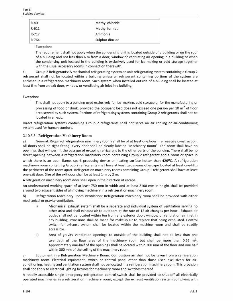
Part 8 Building Services
8‐108 Vol. 3
R‐40
R‐611
R‐717
R‐764
Methyl chloride
Methyl format
Ammonia
Sulphur dioxide
Exception:
The requirement shall not apply when the condensing unit is located outside of a building or on the roof of a building and not less than 6 m from a door, window or ventilating air opening in a building or when the condensing unit located in the building is exclusively used for ice making or cold storage together with the usual accessory rooms in connection therewith.
c) Group 2 Refrigerants: A mechanical refrigerating system or unit refrigerating system containing a Group 2 refrigerant shall not be located within a building unless all refrigerant containing portions of the system are enclosed in a refrigeration machinery room. Such system when installed outside of a building shall be located at least 6 m from an exit door, window or ventilating air inlet in a building.
Exception:
This shall not apply to a building used exclusively for ice making, cold storage or for the manufacturing or
processing of food or drink, provided the occupant load does not exceed one person per 10 m2 of floor area served by such system. Portions of refrigerating systems containing Group 2 refrigerants shall not be located in an exit.
Direct refrigeration systems containing Group 2 refrigerants shall not serve an air cooling or air‐conditioning system used for human comfort.
2.10.3.3 Refrigeration Machinery Room a) General: Required refrigeration machinery rooms shall be of at least one hour fire resistive construction. All doors shall be tight fitting. Every door shall be clearly labeled "Machinery Room". The room shall have no openings that will permit the passage of escaping refrigerant to the other parts of the building. There shall be no direct opening between a refrigeration machinery room containing Group 2 refrigerant and a room or space in
which there is an open flame, spark producing device or heating surface hotter than 426oC. A refrigeration machinery room containing Group 2 refrigerants shall have at least two means of escape located at least one‐fifth the perimeter of the room apart. Refrigeration machinery rooms containing Group 1 refrigerant shall have at least one exit door. Size of the exit door shall be at least 1 m by 2 m.
A refrigeration machinery room door shall open in the direction of escape.
An unobstructed working space of at least 750 mm in width and at least 2100 mm in height shall be provided around two adjacent sides of all moving machinery in a refrigeration machinery room.
b) Refrigeration Machinery Room Ventilation: Refrigeration machinery room shall be provided with either mechanical or gravity ventilation.
i) Mechanical exhaust system shall be a separate and individual system of ventilation serving no other area and shall exhaust air to outdoors at the rate of 12 air changes per hour. Exhaust air outlet shall not be located within 6m from any exterior door, window or ventilation air inlet in any building. Provisions shall be made for makeup air to replace that being exhausted. Control switch for exhaust system shall be located within the machine room and shall be readily accessible.
ii) Area of gravity ventilation openings to outside of the building shall not be less than one
twentieth of the floor area of the machinery room but shall be more than 0.65 m2. Approximately one‐half of the openings shall be located within 300 mm of the floor and one half within 300 mm of the ceiling of the machinery room.
c) Equipment in a Refrigeration Machinery Room: Combustion air shall not be taken from a refrigeration machinery room. Electrical equipment, switch or control panel other than those used exclusively for air‐conditioning, heating and ventilation system shall not be located in a refrigeration machinery room. This provision shall not apply to electrical lighting fixtures for machinery room and switches thereof.
A readily accessible single emergency refrigeration control switch shall be provided to shut off all electrically operated machineries in a refrigeration machinery room, except the exhaust ventilation system complying with

Air‐conditioning, Heating and Ventilation Chapter 2
Bangladesh National Building Code 2012 8‐109
See 2.7.3.3 (b). Such switch shall be located outside the machinery room, within a distance of 3 m from the machinery room exit.
d) First Aid Facility: Each refrigeration machinery room shall be provided with first aid boxes. Refrigeration machinery room containing Group 2 refrigerants shall be provided with two gas masks.
2.10.3.4 Refrigerant Piping and Equipment a) Materials: Materials used in the construction and installation of refrigerating systems shall be suitable for the refrigerant in the system, and no material or equipment shall be installed which will deteriorate due to the chemical action of the refrigerant or the compressor oil, or combination of both.
b) Erection of Refrigerant Piping: Refrigerant piping and tubing shall be installed in such a way so as to prevent excessive vibration and strains at joints and connections. Adequate type of supports shall be used at points as required but not exceeding 4.5 m apart.
Refrigerant piping and tubing shall be installed in such a way so that it is not subject to damage from an external source.
Copper tubing containing other than Group 1 refrigerant shall not be located in a public hallway, lobby or stairway or a building unless enclosed in iron or steel piping and fittings or in rigid metal conduit.
Iron or steel refrigerant piping placed underground shall be coated with sufficient asphalt paint or equivalent material to inhibit corrosion.
c) Refrigerant Containers: A refrigerant receiver or evaporator or condenser shall be constructed in accordance with approved standards.
d) Valves and fittings: All valves and fittings shall be of approved type rated for the maximum operating pressure of the system.
e) Pressure Limiting Device: A pressure limiting device shall be installed on a positive displacement refrigerant compressor which is a portion of:
i) A refrigerating system containing Group 2 refrigerant.
ii) An air cooled refrigerating system containing Group 1 refrigerant of 7.5 kW or more rating.
iii) A water cooled refrigerating system containing Group 1 refrigerant of 2.25 kW or more rating.
A stop or shutoff valve shall not be placed between a pressure limiting device required by this section and the compressor it serves.
f) Pressure Relief Valves: The following compressors of the positive displacement type shall be equipped with a pressure relief valve:
i) A compressor of 15 kW or more rating which is a portion of a refrigeration system containing Group 1 refrigerant and operating at a pressure exceeding 103 kPa in the high pressure side of the system.
ii) A compressor which is a portion of a refrigerating system containing a Group 2 refrigerant.
A pressure relief valve shall be connected to the refrigerant discharge side of the compressor it serves, between such compressor and a stop valve. A stop or shutoff valve shall not be located between a pressure relief valve required by this section and the compressor it serves.
A pressure relief valve, required by this section, that terminate outside, shall discharge at a location at least 4.5 m above the adjoining ground level and at least 6 m from a window, ventilating opening or exit from a building.
g) Pressure Relief Devices for Pressure Vessels: A pressure vessel over 150 mm diameter which may be shut off by valves from other parts of the system shall be equipped with a pressure relief device(s) or rupture member complying with the requirements of this code.
h) Manual Discharge of Group 2 Refrigerant: A refrigerating system located in a building and containing carbon dioxide or Group 2 refrigerant shall be equipped with approved means for manual discharge of the refrigerant to the atmosphere. The discharge pipe shall terminate outside of the building not less than 2 m above the highest structure on the building and at least 6 m from any window, ventilating opening or exit from a building.
2.10.3.5 Storage of Refrigerants Refrigerants not contained in refrigeration system regulated by the Code shall be stored in original containers kept in machinery room. The total amount shall not exceed 135 kg.

Part 8 Building Services
8‐110 Vol. 3
A portable refrigerant container shall not be connected to the refrigerating system for a period longer than is necessary to charge or discharge the refrigerating system.
2.10.4 Cooling Tower
2.10.4.1 Location Cooling Tower shall not be located where warm and humid air discharge from cooling tower is likely to cause damage to building structure.
2.10.4.2 Installation a) Cooling tower located at roof shall meet the requirements of structures as specified in this code.
Clearances for air suction and discharge shall be maintained in accordance with the recommendation of the manufacturer of the cooling tower.
b) Wind speed shall be taken into consideration while designing the foundation/supports for cooling tower.
c) Necessary vibration isolators shall be installed to restrict transmission of machine vibration to the structure.
2.10.4.3 Access An easy access to cooling tower located at roof shall be provided.
2.10.4.4 Waste Water Disposal Cooling towers or evaporative condensers which are equipped with a positive water discharge to prevent excessive build‐up of alkalinity and are used for water cooled condensing units or absorption units shall discharge the water into an approved disposal system.
2.10.4.5 Piping Connections Water supply, waste water piping and other piping connections shall comply with the provisions of applicable codes.
2.10.4.6 Noise Cooling tower noise shall not be more than 65dBA or that approved by the jurisdiction at the property boundary line. If necessary, the fan cylinder may be covered with acoustic materials to attenuate noise. Similarly floating type mat may be used to reduce the water droplet noise.
2.10.4.7 Safety a) Cooling tower fan shall be protected by a strong metal screen so that no external object and/or bird can
come in contact with the fan blades.
b) An electric isolating switch shall be installed, in a locked enclosure, at a suitable location near the cooling tower to disconnect power to the cooling tower fan when maintenance works are to be carried out.
c) Each cooling tower shall be provided with a securely fixed ladder to facilitate maintenance works.
2.11 Ventilation Systems
2.11.1 General
2.11.1.1 Scope The provisions of this section shall govern the ventilation of spaces within a building intended for human occupancy.
2.11.1.2 Where Required Every space intended for human occupancy shall be provided with ventilation by natural or mechanical means during the periods when the room or space is occupied.

Air‐conditioning, Heating and Ventilation Chapter 2
Bangladesh National Building Code 2012 8‐111
2.11.2 Natural Ventilation
2.11.2.1 Sources Natural ventilation of an occupied space shall be through windows, doors, louvers, skylights or other openings to the outdoor. Such ventilating openings shall open to the sky or a public street, space, alley, park, highway, yard, court, plaza or other approved space which comply with the requirements of the building code.
2.11.2.2 Area of Ventilating Openings The minimum ventilating opening to the outdoors shall be four per cent of the floor area being ventilated.
a) Adjoining Spaces: Where rooms and spaces without openings to the outdoors are ventilated through an adjoining room, the unobstructed opening to the adjoining rooms shall be at least eight per cent of the floor area
of the interior room or space, but not less than 2.33 m2. The ventilation openings to the outdoors shall be based on the total floor area being ventilated.
b) Opening Below Grade: Openings below grade shall be acceptable for natural ventilation provided the outside horizontal clear space measured perpendicular to the opening is one and one‐half times the depth below the average adjoining grade.
2.11.2.3 Contaminants Exhausted Naturally ventilated spaces having contaminants present shall comply with the requirements of Sec 2.8.4.
2.11.2.4 LPgas Distribution Facilities LP‐gas distribution facilities shall be provided with air inlets and outlets arranged so that air movement across the floor of the facility will be uniform. The total area of both inlet and outlet openings shall be at least 0.70 per cent of the floor area. The bottom of such openings shall not be more than 150 mm above the floor.
2.11.3 Mechanical Ventilation
2.11.3.1 Where Required Mechanical ventilation shall be provided in all occupiable rooms or spaces where the requirements for natural ventilation are not met; in all rooms or spaces, which because of the nature of their use or occupancy, involve the presence of dust, fumes, gases, vapours, or other noxious or injurious impurities, or substances which create a fire hazard; where space temperature is more than 40º C; where relative humidity of inside air is more than 70 per cent; where job conditions require ventilation; or where required as per provisions of this Code.
2.11.3.2 Ventilation System Mechanical ventilation shall be provided by a method of supply air and return or exhaust air. The amount of supply air shall be approximately equal to the amount of return and exhaust air; however, the system shall not be prohibited from producing a negative or positive pressure. The ventilation system ducts and equipment shall be designed and installed in accordance with Sec 2.5.
2.11.3.3 Ventilation Air Quantity The minimum amount of air circulation rate for ventilation shall be determined based on the occupant load/ space area and use of the building in accordance with Table 8.2.6. The air circulation rate specified in the Table 8.2.6 shall be equal to the combined total of outside air and re‐circulated air. The occupant load shall be determined in accordance with the data provided in table 8.2.3.
2.11.3.4 Minimum Outdoor Air The minimum amount of the outdoor air shall be in accordance with Table 8.2.3.
Mandatory requirement: in no case the ventilation air quantity shall be lower than 2.5 l/s per person.
2.11.3.5 Air temperature
The temperature differential between ventilation air and air in the conditioned space shall not exceed 5.5oC.
Exception:
Ventilation air that is part of the air‐conditioning system.

Part 8 Building Services
8‐112 Vol. 3
2.11.3.6 Recirculation a) Amount of Recirculation: Not more than 67 per cent of the required ventilation air specified in Table 8.2.6 shall be permitted for recirculation, when the concentration of particulates is less than specified in Table 8.2.7. Air in excess of the required ventilation air shall be permitted to be completely recirculated. Air shall not be recirculated to another dwelling unit or occupancy of dissimilar use.
Not more than 85 per cent of the required ventilation air shall be permitted for recirculation when the system is equipped with effective adsorption or filtering equipment so that the condition of the air supplied to the room or space is within the quality limitations of Table 8.2.7.
b) Prohibited Use of Recirculated Air: Air drawn from mortuary rooms, bathrooms or toilets or any space where an objectionable quantity of flammable vapours, dust, odours, or noxious gases is present shall not be recirculated. Air drawn from rooms that must be isolated to prevent the spread of infection shall not be recirculated.
Exception:
Air drawn from hospital operating rooms may be recirculated, if the following requirements are met:
i) A minimum of twenty five total air changes per hour shall be provided, of which five air changes per hour shall be outdoor air.
ii) All fans serving exhaust systems are located at the discharge end of the system.
iii) Outdoor air intakes shall be located at least 7.5 m from exhaust outlets of ventilation systems, combustion equipment stacks, medical surgical vacuum systems, plumbing vent stacks or from areas which may collect vehicular exhaust and other noxious fumes. The bottom of outdoor air intakes serving central systems shall be located at least 2 m above ground level, or if installed above roof, at least 1 m above roof level.
iv) Positive air pressure shall be maintained at all times in relation to adjacent areas.
v) All ventilation or air‐conditioning systems serving such rooms shall be equipped with a filter bed of twenty five per cent efficiency upstream of air‐conditioning equipment and a filter bed of ninetynine per cent efficiency downstream of the supply fan, any recirculating spray water systems and water reservoir type humidifiers. All filter efficiencies shall be average atmospheric dust spot efficiencies tested in accordance with the latest ASHRAE standard.
vi) Duct linings shall not be used in air‐conditioning and ventilation systems serving such rooms unless terminal filters of at least ninety per cent efficiency are installed downstream of linings.
vii) Air supplied shall be delivered at or near the ceilings and all exhaust air shall be removed near floor level, with at least two exhaust outlets not less than 75 mm above the floor.
c) Swimming Pool Area Recirculation: Return air from a swimming pool and deck area shall be permitted to be recirculated in accordance with Sec 2.8.3.6(a) when such air is dehumidified to maintain the relative humidity of the area at 60 per cent or less. The return air shall only be recirculated to the area from which it was removed.
2.11.3.7 Ventilation in Uninhabited Spaces Uninhabited spaces, such as crawl spaces or attics, shall be provided with natural ventilation openings as required by Building Code or such spaces shall be mechanically ventilated. The mechanical ventilation system shall be a mechanical exhaust and supply air system. The exhaust rate shall be 0.1 l/s per square metre of horizontal area. The ventilation system shall operate when the relative humidity exceeds 70 per cent in the space.
2.11.3.8 Ventilation in Enclosed Parking Garages: Mechanical ventilation systems for enclosed parking garages shall be permitted to operate intermittently where the system is arranged to operate automatically upon detection of vehicle operation or the presence of occupants or sensing the CO concentration level by approved automatic detection devices.
Average concentration of CO shall not exceed 35 ppm with a maximum of 200 ppm. Automatic operation of the system shall not reduce the ventilation air flow rate below .25 l/s.m2 of the floor area and the system shall be capable of producing a ventilation air flow rate of 7.6 l/s.m2 of floor area. In no case the outdoor air quantity shall be lower than 5 l/s per m2 of floor area.
Connecting offices, waiting rooms, ticket booths and similar uses that are accessory to a public garage shall be maintained at a positive pressure.

Air‐conditioning, Heating and Ventilation Chapter 2
Bangladesh National Building Code 2012 8‐113
2.11.4 Mechanical Exhaust
2.11.4.1 Where Required All rooms and areas having air with dust particles sufficiently light enough to float in the air, odours, fumes, spray, gases, vapours, smoke, or other noxious or impurities in such quantities as to be irritating or injurious to health or safety or which is harmful to building and materials or has substances which create a fire hazard, and rooms or areas as indicated in Table 8.2.6 shall have air exhausted to the outdoors in accordance with this section.
2.11.4.2 Design of Exhaust System a) General: The design of the system shall be such that the emissions or contaminants are confined to the area in which they are generated by currents, hoods or enclosures and shall be exhausted by a duct system to a safe location or treated to remove contaminants. Ducts conveying explosives or flammable vapours, fumes or dusts shall extend directly to the exterior of the building without entering other spaces. Exhaust ducts shall not extend into or through ducts or plenums.
Exception:
Ducts conveying vapour or fumes having flammable constituents less than 25 per cent of their lower flammability limit (LFL) may pass through other spaces.
Table 8.2.6 Required Minimum Air Circulation Rate for Mechanical Ventilation of Non‐Air Conditioned Space
SI NO Application Air Change per Hour
1.
2.
3.
4.
5.
6.
7.
8.
9.
10.
11.
12.
13.
14.
15.
16.
17.
18.
19.
20.
21.
22.
23.
24.
25.
26.
27.
28.
Assembly rooms
Bakeries
Banks/building societies
Bathrooms
Bedrooms
Billiard rooms
Boiler rooms
Cafes and coffee bars
Canteens
Cellars
Churches
Cinemas and theatres
Club rooms
Compressor rooms
Conference rooms
Dairies
Dance halls
Dye works
Electroplating shops
Engine rooms
Entrance halls
Factories and work shops
Foundries
Garages
Glass houses
Gymnasium
Hair dressing saloon
Hospitals‐sterilizing
4‐8
20‐30
4‐8
6‐10
2‐4
6‐8
15‐30
10‐12
8‐12
3‐1o
1‐3
10‐15
12, Min
10‐12
8‐12
8‐12
12, Min
20‐30
10‐12
15‐30
3‐5
8‐10
15‐30
6‐8a
25‐60
6, Min
10‐15
15‐25

Part 8 Building Services
8‐114 Vol. 3
SI NO Application Air Change per Hour
29.
30.
31.
32.
33.
34.
35.
36.
37.
38.
39.
40.
41.
42.
43.
44.
45.
46.
47.
48.
49.
50.
51.
52.
53.
54.
Hospital‐wards
Hospital domestic
Laboratories
Launderettes
Laundries
Lavatories
Lecture theatres
Libraries
Living rooms
Mushroom houses
Offices
Paint shops (not cellulose)
Photo and X‐ray darkroom
Public house bars
Recording control rooms
Recording studios
Restaurants
Schoolrooms
Shops and supermarkets
Shower baths
Stores and warehouses
Squash courts
Swimming baths
Toilets
Utility rooms
Welding shops
6‐8
15‐20
6‐15
10‐15
10‐30
6‐15
5‐8
3‐5
3‐6
6‐10
6‐10
10‐20
10‐15
12, Min
15‐25
10‐12
8‐12
5‐7
8‐15
15‐20
3‐6
4, Min
10‐15
6‐10
15‐20
15‐30
NOTE
a : Only outdoor air and no recirculation shall be done.
: The ventilation rates may be increased by 50 percent where heavy smoking occurs or if the room is below ground.
Table 8.2.7 Maximum Allowable Contaminant Concentrations
Contaminant Annual Average (arithmetic mean)
µg/m3
Short Term Level
(not to be exceeded more
than once a year) µg/m3
Averaging
Period
(hours)
Particulates
Sulfur oxides
Carbon monoxide
Photochemical oxidant
Hydrocarbons (not
including methane)
Nitrogen oxides
Odour
60
80
20,000
100
1,800
200
‐‐
150
400
30,000
500
4,000
500
Essentially unobjectionable a
24
24
8
1
3
24
‐‐

Air‐conditioning, Heating and Ventilation Chapter 2
Bangladesh National Building Code 2012 8‐115
Note: a Judged unobjectionable by 60 per cent of a panel of 10 untrained subjects.
Separate and distinct systems shall be provided for incompatible exhaust materials.
Contaminated air shall not be recirculated to occupied areas unless contaminants have been removed. Air contaminated with explosive or flammable vapours, fumes or dusts; flammable or toxic gases; or radioactive material shall not be recirculated.
b) Exhaust Air Inlet: The inlet to the exhaust system shall be located in the area of heaviest concentration of contaminants.
c) Velocity and Circulation: The velocity and circulation of air in work areas shall be such that contaminants are captured by an air stream at the area where the emissions are generated and conveyed into a product ‐ conveying duct system. Mixtures within work areas where contaminants are generated shall be diluted below 25 per cent of their lower explosive limit or lower flammability limit with air which does not contain other contaminants.
2.11.4.3 Make Up Air Make up air shall be provided to replenish air exhausted by the ventilating system. Make up air intakes shall be located so as to avoid recirculation of contaminated air within enclosures.
2.11.4.4 Hoods and Enclosures Hoods and enclosures shall be used when contaminants originate in a concentrated area. The design of the hood or enclosure shall be such that air currents created by the exhaust systems will capture the contaminants and transport them directly to the exhaust duct. The volume of air shall be sufficient to dilute explosive or flammable vapours, fumes or dusts as set forth in Sec 2.11.4.2(c).
2.11.4.5 Exhaust Outlets The termination point for exhaust ducts discharging to the atmosphere shall not be less than the following:
a) Ducts conveying explosive or flammable vapours, fumes or dusts: 9 m from property line; 3 m from opening into the building; 2 m from exterior walls or roofs; 9 m from combustible walls or openings into the building which are in the direction of the exhaust discharge; 3 m above adjoining grade.
b) Other product conveying duct outlets: 3 m from property line; 1 m from exterior wall or roof; 3 m from openings into the buildings; 1 m above adjoining grade.
c) Domestic kitchen, bathroom, domestic clothes dryer exhaust duct outlets: 1 m from property line; 1 m from opening into the building.
d) Outlets for exhausts that exceed 80oC shall be in accordance with the relevant code.
2.11.4.6 Motors and Fans a) General: Motors and fans shall be sized to provide the required air movement. Motors in areas which contain flammable vapours and dusts shall be of a type approved for such environments. A manually operated remote control device shall be installed to shutoff fans or blowers in flammable vapour or dust system. Such control device shall be installed at an approved location.
Electrical equipment used in operations that generate explosive or flammable vapours, fumes or dusts shall be interlocked with the ventilation system so that the equipment cannot be operated unless the ventilation fans are in operation. Motors for fans used to convey flammable vapours or dusts shall be located outside the duct and shall be protected with approved shields and dust proofing. Motors and fans shall be accessible for servicing and maintenance.
b) Fans: Parts of fans in contact with explosive or flammable vapours, fumes or dusts shall be of nonferrous or non‐sparking materials or their casing shall be lined or constructed of such material. When the size and hardness of materials passing through a fan could produce a spark, both the fan and the casing shall be of non‐sparking materials. When fans are required to be spark resistant, their bearings shall not be within the air stream, and all parts of the fan shall be grounded. Fans in systems handling materials that are likely to clog the blades, and fans in buffing or woodworking exhaust systems, shall be of the radial blade or tube axial type.
Equipment used to exhaust explosive or flammable vapours, fumes or dusts shall bear an identification plate stating the ventilation rate for which the system was designed.

Part 8 Building Services
8‐116 Vol. 3
Fans located in systems conveying corrosives shall be of materials that are resistant to the corrosion or shall be coated with corrosion resistant materials.
2.11.4.7 Exhaust Systems of Special Areas a) Motor Vehicle Operation: In areas where motor vehicles operate for a period of time exceeding 10 seconds, the ventilation return air shall be exhausted. In fuel dispensing areas, the bottom of the air inlet or exhaust opening shall be located a maximum of 450 mm above the floor.
b) Spray Painting and Dipping Rooms: Rooms booth for spray painting or dipping shall have a mechanical exhaust systems which create a cross‐sectional air velocity of 0.5 m/s. The system shall provide a uniform exhaust of air across the width and height of the room or booth. The exhaust system shall operate while spray painting or dipping is being done.
c) Motion Picture Projectors: Projectors equipped with an exhaust discharge shall be directly connected to a mechanical exhaust system. The exhaust system shall operate at an exhaust rate as indicated by the manufacturer's instructions.
Projectors without an exhaust shall have contaminants exhausted through a mechanical exhaust system. The exhaust rate for electric arc projectors shall be a minimum of 100 l/s per lamp. The exhaust rate for xenon projectors shall be a minimum of 150 l/s per lamp. The lamp and projection room exhaust systems, if combined or independent, shall not be interconnected with any other exhaust or return system within the building.
d) Dry Cleaning Equipment: Dry cleaning equipment shall be provided with an exhaust system capable of maintaining a minimum air velocity of 0.5 m/s across the face of the loading door.
e) LP gas Distribution Facilities: LP gas distribution facilities that are not provided with natural ventilation shall have a continuously operating exhaust system at the rate of 5 l/s per square metre of floor area. The bottom of air inlet and outlet openings shall not be more than 150 mm above the floor.
2.11.4.8 Exhaust System Ducts a) Construction: Ducts for exhaust systems shall be constructed of materials approved for the type of particulates conveyed and as per latest standard in this regard. Ducts shall be of substantial airtight construction and shall not have openings other than those required for operation and maintenance of the system.
b) Supports: Spacing of supports for ducts shall not exceed 3.7 m for 200 mm ducts and 6 m for larger ducts unless justified by the design. The design of supports shall assume that 50 per cent of the duct is full of the particulate being conveyed.
c) Explosion Venting: Ducts conveying explosive dusts shall have explosion vents, openings protected by antiflash‐back swing valves or rupture diaphragms. Openings to relieve explosive forces shall be located outside the building.
d) Fire Protection: Fire suppression system shall be installed within ducts having a cross‐sectional dimension exceeding 250 mm when the duct conveys flammable vapours or fumes.
e) Clearances: Ducts conveying flammable or explosive vapours, fumes or dusts shall have a clearance from combustibles of not less than 450 mm.
2.11.5 Kitchen Exhaust Equipment
2.11.5.1 Kitchen Exhaust Ducts a) Materials: Kitchen exhaust ducts and plenums shall be constructed of at least 16 SWG steel or 18 SWG stainless steel sheet.
Joints and seams shall be made with a continuous liquid tight weld or braze made on the external surface of the duct system. A vibration isolator connector may be used, provided it consists of noncombustible packing in a metal sleeve joint of approved design. Duct bracing and supports shall be of noncombustible material securely attached to the structure and designed to carry gravity and lateral loads within the stress limitations of the Building Code. Bolts, screws, rivets and other mechanical fasteners shall not penetrate duct walls. Exhaust fan housings shall be constructed of steel.
Exception:
Kitchen exhaust ducts which are exclusively used for collecting and removing steam, vapour, heat or odour may be constructed as per provisions of Sec 2.4.1.

Air‐conditioning, Heating and Ventilation Chapter 2
Bangladesh National Building Code 2012 8‐117
b) Corrosion Protection: Ducts exposed to the outside atmosphere or subject to a corrosive environment shall be protected against corrosion. Galvanization of metal parts, protection with noncorrosive paints and waterproof insulation are considered acceptable methods of protection.
c) Prevention of Grease Accumulation: Duct systems shall be so constructed and installed that grease cannot become pocketed in any portion thereof, and the system shall have a slope not less than 1 in 48 towards the hood or an approved grease reservoir. Where the horizontal ducts exceed 23 m in length the slope shall not be less than 1 in 12.
d) Air Velocity: The air velocity in the duct shall be a minimum of 7.62 m/s and a maximum of 12.7 m/s.
e) Cleanouts and Other Openings: Duct systems shall not have openings other than those required for proper operation and maintenance of the system. Any portion of such system having sections inaccessible from the duct entry or discharge shall be provided with adequate cleanout openings of approved construction spaced not more than 6 m apart. The cleanout shall be located on the side of the duct having a minimum opening dimension of 300 mm or the width of the duct when less than 300 mm.
f) Duct Enclosure: The duct which penetrates a ceiling, wall or floor shall be enclosed in a fire‐resistant rated enclosure from the point of penetration in accordance with the Building Code. The duct enclosure shall be sealed around the duct at the point of penetration and vented to the exterior through weather‐protected openings. The clearance between the duct enclosure and the duct shall be at least 75 mm and not more than 300 mm. Each duct enclosure shall contain only one exhaust duct. Approved fire rated access openings shall be provided at cleanout points.
g) Kitchen exhaust air flow rate shall be calculated based on the data provided in Table 8.2.8.
Table 8.2.8 Design Exhaust Air Flow in I/s per kW of the Kitchen Equipment
SI
Kitchen Equipment
Electricity based
Equipment
Gas based
Equipment
(a) (b) © (d)
1.
2.
3.
4.
5.
6.
7.
8.
9.
10.
11.
12.
13.
14.
15.
16.
17.
Cooking pot
Pressure cooker cabinet
Convection oven
Roasting oven (salamander)
Griddle
Frying pan
Deep fat fryer
Cooker/stove
Grill
Heated table/bath
Coffeemaker
Dish washer
Refrigeration equipment
Ceramic cooker/stove
Microwave oven
Pizza oven
Induction cooker/stove
8
5
10
33
32
32
28
32
50
30
3
17
60
25
3
15
20
12
33
35
35
35
61
2.11.5.2 Kitchen Exhaust Hoods a) A commercial exhaust hood shall be provided for each commercial cooking appliance.
Exceptions:
i) An appliance located within a dwelling unit and not used for commercial purposes.
ii) Completely enclosed ovens.
iii) Steam tables.

Part 8 Building Services
8‐118 Vol. 3
iv) Auxiliary cooking equipment that does not produce grease laden vapours, including toasters, coffee makers and egg cookers.
b) Domestic cooking appliances used for commercial purposes shall be provided with a commercial exhaust hood. Domestic cooking appliances used for noncommercial purposes shall be provided with ventilation in accordance with Sec 2.8.
c) Hood Construction: The hood and other parts of the primary collection system shall be constructed of galvanized steel, stainless steel, copper or other material approved by the Building Official for the use intended. The minimum nominal thickness of the galvanized steel shall be 1.2 mm (No. 18 SWG). The minimum nominal thickness of stainless steel shall be 0.93 mm (No. 20 SWG). Hoods constructed of copper shall be of copper sheets
weighing at least 7.33 kg/m2. All external joints shall be welded liquid tight. Hoods shall be secured in place in noncombustible supports.
d) Interior Surface: The interior surfaces of the hood shall not have any areas that can accumulate grease.
Exception:
Grease collection systems under fitters and troughs on the perimeter of canopy hoods.
e) Canopy Hoods: Canopy hoods shall be designed to completely cover the cooking equipment. The edge of the hood shall extend a minimum horizontal distance of 150 mm beyond the edge of the cooking surface on all open sides and the vertical distance between the lip of the hood and the cooking surface shall not exceed 1.22 m.
f) Non‐canopy Type Hoods: Hoods of the non canopy‐type shall be located a maximum of 900 mm above the cooking surface. The edge of the hood shall be set back a maximum of 300 mm from the edge of the cooking surface.
g) Hood Exhaust : The hood exhaust shall create a draft from the cooking surface into the hood. Canopy
hoods attached to wall shall exhaust a minimum of 500 l/s per m2 of the hood area. Canopy hoods exposed on all
sides shall exhaust a minimum of 750 l/s per m2 of hood area. Hoods of the non canopy type shall exhaust a minimum of 460 l/s per lineal metre of cooking surface.
h) Exhaust Outlet : An exhaust outlet within the hood shall be so located as to optimize the capture of particulate matter. Each outlet shall serve not more than a 3.7 m section of the hood.
2.11.5.3 Make Up Air Make up air shall be supplied during the operation of the kitchen exhaust system. The amount of make up air shall be approximately equal to the amount of the exhaust air. The make up air shall be supplied in such a way as to avoid short circuiting and reducing the effectiveness of the exhaust system. Windows and doors shall not be used for the purpose of providing make up air.
2.11.5.4 Grease Removal The air exhausted in every commercial exhaust hood shall pass through approved grease filters or grease removal device designed for the specific purpose. Grease removal devices shall bear the label of an approved agency, and shall be installed in accordance with the manufacturer's instructions for the labeled equipment. All grease filters shall be accessible. Grease filters shall be installed at a minimum angle of 45 degrees to the horizontal. The filters shall be arranged so as to capture and drain grease to a point of collection.
2.11.5.5 Motors, Fans and Safety Devices a) Motors and fans shall be of sufficient capacity to provide required air movement. Electrical equipment shall be approved for the class of use as provided in the Electrical Code. Motors and fans shall be accessible for servicing and maintenance. Motors of the exhaust fan shall not be installed within the ducts or under hoods.
b) Commercial exhaust system hoods and ducts shall have a minimum clearance to combustibles of 450 mm.
c) Fire Suppression System Required: All commercial cooking surfaces, kitchen exhaust systems, grease removal devices and hoods shall be protected with an approved automatic fire suppression system in accordance with the Building Code.

Air‐conditioning, Heating and Ventilation Chapter 2
Bangladesh National Building Code 2012 8‐119
2.12 ENERGY CONSERVATION
2.12.1 General
Air‐conditioning, heating and ventilation systems of all buildings shall be designed and installed for efficient use of energy as herein provided. Calculations of cooling and heating loads shall be based on data which lead to a system with optimum energy use.
General standards of comfort or particular environmental requirements within the building shall not be sacrificed in an endeavor to achieve low consumption of energy. For special applications, such as hospitals, laboratories, thermally sensitive equipment, computer rooms and manufacturing processes, the design concepts and parameters shall conform to the requirements of the application at minimum energy levels.
2.12.2 Design Parameters
2.12.2.1 Outdoor Design Conditions Unless specifically required, the outdoor design temperature shall be selected from columns of 2 per cent value of Table 8.2.2 for cooling.
2.12.2.2 Indoor Design Conditions Indoor design temperature shall not be less than 24ºC for cooling unless otherwise required for specific application.
2.12.2.3 Humidity The actual design relative humidity shall be selected from the range shown in Table 8.2.1 for the minimum total air‐conditioning, heating and ventilation system energy use.
2.12.3 System Design
2.12.3.1 Load Variation Consideration shall be given to changes in building load and the system designed, so that maximum operational efficiency is maintained under part load conditions. The total system shall be separated into smaller zones having similar load requirements, so that each zone can be separately controlled to maintain optimum operating conditions by reducing wastage of energy.
2.12.3.2 Temperature of Cooling Media The temperature of refrigerant, chilled water or brine circulated within the system shall be maintained at the level necessary to achieve the required output to match the prevailing load conditions with the minimum expenditure of energy.
2.12.3.3 Energy Recovery Where possible energy recovery system shall be adopted.
2.12.4 Equipment and Control
2.12.4.1 General Air‐conditioning, heating and ventilation system shall be equipped with devices and controls to automatically control the capacity of the system when the building requirement reduces. The control system shall have devices to reduce energy use considering the effect of building energy storage.
2.12.4.2 Cooling with Outdoor Air Each air handling system shall have facility to use up to and including 100 per cent of the air handling system capacity for cooling with outdoor air automatically whenever the use of outdoor air will result in lower usage of energy than would be required under normal operation of the air handling system.
Exception:
Cooling with outdoor air is not required under any one or more of the following conditions:
a) Where the air handling system capacity is less than 2500 l/s or 40 kW total cooling capacity.

Part 8 Building Services
8‐120 Vol. 3
b) Where the quality of outdoor air is so poor as to require extensive treatment of the air.
c) Where the need for humidification or dehumidification requires the use of more energy than is conserved by outdoor air cooling on an annual basis.
d) Where the use of outdoor air cooling would affect the operation of other systems so as to increase the overall energy consumption of the building.
2.12.4.3 Mechanical Ventilation Each mechanical ventilation system shall be equipped with a readily accessible means for either shutoff or volume reduction, and shutoff when ventilation is not required. Automatic or gravity dampers that close when the system is not operating shall be provided for outdoor air intakes and exhausts.
2.12.4.4 Maintenance Heat exchange tubes shall be periodically cleaned to maintain its heat transfer characteristics. Maintenance of all equipment shall be periodically done to maintain its efficiency at satisfactory level.
2.12.4.5 Minimum Equipment Efficiencies Cooling equipment shall meet or exceed the minimum efficiency requirements presented in Tables 8.2.9 through 8.2.10. Heating and cooling equipment not listed here shall comply with ASHRAE 90.1‐2004 § 6.4.1.
Table 8.2.9 Minimum Performance of Unitary Air Conditioning Equipment
Equipment Class Minimum COP
Minimum IPLV
Test Standard
Unitary Air Cooled Air Conditioner ≥ 19 and <40 KW (≥5.4 and <11 tons)
3.08 ‐‐ ARI 210/240
Unitary Air Cooled Air Conditioner ≥ 40 to <70 KW (≥11 to <20 tons)
3.08 ‐‐ ARI 340/360
Unitary Air Cooled Air Conditioner ≥70 KW (≥20 tons)
2.93 2.99 ARI 340/360
Unitary water Cooled Air Conditioner <19 KW (<5.4 tons)
4.10 ‐‐ ARI 210/240
Unitary water Cooled Air Conditioner ≥ 19 and <40 KW (≥5.4 and <11 tons)
4.10 ‐‐ ARI 210/240
Unitary water Cooled Air Conditioner ≥<40 KW (≥11 tons)
3.22 3.02 ARI 210/240
Table 8.2.10 Minimum Performance of Chillers
Equipment Class Size category Minimum COP
Minimum IPLV
Test Standard
Air cooled Chiller, electrically operated
<530 KW (<150 tons)
2.90 3.16 ARI 550/590‐
1998
Air cooled Chiller, electrically operated
≥530 KW (≥150 tons)
3.05 3.32 ARI 550/590‐1998
Centrifugal Water Cooled, electrically operated
Chiller <530 KW (<150 tons)
5.80 6.09 ARI 550/590‐
1998

Air‐conditioning, Heating and Ventilation Chapter 2
Bangladesh National Building Code 2012 8‐121
Equipment Class Size category Minimum COP
Minimum IPLV
Test Standard
Centrifugal Water Cooled Chiller, electrically operated
≥530 and <1050 KW (≥150 and <300 tons)
5.80 6.17 ARI 550/590‐
1998
Centrifugal Water Cooled Chiller, electrically operated
≥1050 KW (≥300 tons)
6.30 6.61 ARI 550/590‐
1998
Reciprocating Compressor, Water Cooled Chiller, electrically operated
All Capacities 4.20 5.05 ARI 550/590‐
1998
Rotary Screw and Scroll Compressor, Water Cooled Chiller, electrically operated
<530 KW (<150 tons)
4.70 5.49 ARI 550/590‐
1998
Rotary Screw and Scroll Compressor, Water Cooled Chiller, electrically operated
≥530 and <1050KW
(≥150 and <300 tons)
5.40 6.17 ARI 550/590‐
1998
Rotary Screw and Scroll Compressor, Water Cooled Chiller, electrically operated
≥1050 KW (≥300 tons)
5.75 6.43 ARI 550/590‐
1998
Air cooled Absorption, Single Effect
All Capacities 0.60 ‐‐ ARI 560
Water Cooled Absorption, Single Effect
All Capacities 0.70 ‐‐ ARI 560
Absorption, Double Effect, Indirect Fired
All Capacities 1.00 1.05 ARI 560
Absorption, Double Effect, Direct Fired
All Capacities 1.00 1.00 ARI 560
2.12.4.6 Controls a) All mechanical cooling and heating shall be controlled by a timeclock that:
(i) Can start and stop the system under different schedules for three different day‐types per week.
(ii) Is capable of retaining programming and time setting during a loss of power for a period of at least 10 hours, and
(iii) Includes an accessible manual override that allows temporary operation of the system for up to 2 hours.
Exceptions:
Cooling systems < 28 kw (8 tons)
Heating systems < 7 kw (2 tons)
b) All heating and cooling equipment shall be temperature controlled. Where a unit provides both heating and cooling, controls shall be capable of providing a temperature dead band of 3° (5°F) within which the supply of heating and cooling energy to the zone is shut off or reduced to a minimum. Where separate heating and cooling equipment serve the same temperature zone, thermostats shall be interlocked to prevent simultaneous heating and cooling.

Part 8 Building Services
8‐122 Vol. 3
c) All cooling towers and closed fluid coolers shall have either two speed motors, pony motors, or variable speed drives controlling the fans.
2.12.5 System Balancing
2.12.5.1 General Construction documents shall require that all HVAC systems be balanced in accordance with generally accepted engineering standards.
Construction documents shall require that a written balance report be provided to the owner or the designed representative of the building owner for HVAC system servicing zones with a total conditioned area exceeding 500 m2 (5000 ft2).
a) Air System Balancing
Air systems shall be balanced in a manner to first minimize throttling loses. Then, for fans with fan system power greater than 0.75 KW (1.0 hp), fan speed shall be adjusted to meet design flow conditions.
b) Hydronic System Balancing
Hydronic systems shall be proportionately balanced in a manner to first minimize throttling loses; then the pump impeller shall be trimmed or pump speed shall be adjusted to meet design flow conditions.
Exceptions:
(i) Impellers need not be trimmed nor pump speed adjusted for pumps with pump motors of 7.5 KW (10 hp) or less.
(ii) Impellers need not be trimmed when throttling results in no greater than 5% of the nameplate horse power draw, or 2.2 KW (3hp), whichever is greater.
2.12.6 Condensers
2.12.6.1 Condenser Locations Care shall be exercised in locating the condensers in such a manner that heat sink is free of interference from heat discharge by devices located in adjoining spaces and also does not interfere with such other systems installed nearby.
2.12.6.2 Treatment Water for Condensers All high‐rise buildings using centralized cooling water system shall use soft water for the condenser and chilled water‐system.
2.12.7 Economizers
2.12.7.1 Air side Economizer Each individual cooling fan system that has a design supply capacity over 1,200 l/s (2,500 cfm) and a total mechanical cooling capacity over 22 KW (6.3 tons) shall include either:
(a) An air economizer capable of modulating outside‐air and return‐air dampers to supply 100 percent of the design supply air quantity as outside‐air; or
(b) A water economizer capable of providing 100% of the expected system cooling load at outside air temperature of 10°C(50°F) dry‐bulb/ 7.2°C (45°F) wet‐bulb and below:
Exception:
i) Projects in the Hot‐Dry and Warm‐Humid climate zones are exempt.
ii) Individual ceiling mounted fan systems <3,200 l/s (6,500 cfm) are exempt.
2.12.7.2 where required by 2.12.7.1 economizers shall be capable of providing partial cooling even when additional mechanical cooling is required to meet the cooling load.

Air‐conditioning, Heating and Ventilation Chapter 2
Bangladesh National Building Code 2012 8‐123
2.12.8 Variable FlowHydronic Systems
2.12.8.1 Chilled or hot‐water systems shall be designed for variable fluid flow and shall be capable of reducing pump flow rates to no more than the larger of:
(a) 50% of the design flow rate, or
(b) the minimum flow required by the equipment manufacturer for proper operation of the chillers or boilers.
2.12.8.2 Water cooled air‐conditioning or heat pump units with a circulation pump motor greater than or equal to 3.7 KW (5hp) shall have two‐way automatic isolation valves on each water cooled air‐conditioning or heat pump unit that are interlocked with the compressor to shut off condenser water flow when the compressor is not operating.
2.12.8.3 Chilled water or condenser water systems that must comply with either 2.12.8.1 or 2 .12.8.2 and that have pump motors greater than or equal to 3.7 KW (5hp) shall be controlled by variable speed drives.
2.13 Inspection, Testing and Commissioning
2.13.1 Inspection and Testing
2.13.1.1 General All air‐conditioning, heating and ventilation system shall be inspected and tested by the Authority before the system is commissioned for normal operation. It should be ensured that these are carried out thoroughly and that all data and results are properly documented. It is recommended that whole inspection, testing and commissioning be done under the guidance and control of a single Authority.
2.13.1.2 Inspection All machinery, equipment and other accessories of the air‐conditioning, heating and ventilation system shall be inspected by the Authority to determine whether the system components and the system as a whole has been installed as per design and provisions of this Code; proper safety requirements have been maintained; and adequate fire protection measures have been taken.
Inspection shall also be carried out on structural supports, hangers, fastening devices, vibration isolators etc.
2.13.1.3 Testing
a) General: All machinery, equipment and other accessories shall be tested as per approved procedures. Tests shall be conducted to determine the strength capacity of any item and performance of any machine and equipment. All test data shall be properly documented.
b) Pressure Testing of Piping: All field installed refrigerant and hydronic piping system along with their valves and pipe fittings shall be tested at their approved test pressures to determine whether the piping system can withstand the test pressures.
c) Air Distribution System Testing: All ducting system shall be tested to determine whether the duct system has any leakage at test pressures. All air terminals and air dampers shall be tested for their flow characteristics.
d) Machinery and Equipment: Tests shall be conducted on machinery and equipment to determine whether these operate and function properly. All machinery and equipment shall also be tested for their electrical power consumption characteristics and overall performance. Before performance testing of the system all air distribution system and hydronic system shall be properly balanced by approved procedure.
e) Safety Devices and Controls: Tests shall be carried out to determine whether the safety devices and controls function properly.
f) All air filters shall be tested in accordance with the latest standard.

Part 8 Building Services
8‐124 Vol. 3
2.13.2 Commissioning
If the Authority becomes satisfied regarding satisfactory installation and performance of the air‐conditioning, heating and ventilation system after testing, the system shall be commissioned following approved procedure. Before complete commissioning, all air distribution systems and hydronic systems shall be properly balanced and all the controls and their sensors shall be properly adjusted.
2.14 Operation and Maintenance
2.14.1 General
The owner of the building where the air‐conditioning, heating and ventilation system is installed, shall follow a properly designed operation procedure and maintenance schedule.
2.14.2 Operation
A well sequenced operation procedure shall be followed to ensure effective operation of the air‐conditioning, heating and ventilation system, safety from hazard to personnel and property. Operation procedure shall take account for saving in energy use.
All operational data of all the machinery and equipment shall be properly recorded for determination of performance of the machinery, equipment and the system. These data shall be properly preserved for future reference for maintenance purposes.
2.14.3 Maintenance
A well designed maintenance program for the air‐conditioning, heating and ventilation system shall be implemented in order to achieve the following:
a) Optimum reliability and continuity of service.
b) Extended longevity and economic life.
c) Functional effectiveness, whereby the intended performance of mechanical equipment and system can be fully attained.
d) Minimum operating cost, attendant requirements, servicing and repairs.
e) Safety from hazard to personnel and property.
Maintenance program and procedure shall comply with the instructions of machinery/equipment manufacturers in this regard.