airconditioning - recool watergekoelde airconditioning... · stulz comptrol 1002 is a complete...
TRANSCRIPT

AIRCONDITIONINGMICROPROCESSORMICROPROCESSOR
CompTrol 1002
INDEX 50
Edition 5.97
TECHNICAL MANUAL

E/0597/50 /2
Contents Page
1. Features ................................................................................................................ 3
2. Operation and Status Elements .......................................................................... 4
3. Start-up.................................................................................................................. 6
4. Menue .................................................................................................................. 10
5. Alarms and Failures ........................................................................................... 21
6. Control Scheme .................................................................................................. 24
7. Specification C1002 ........................................................................................... 26Technical DataConnection Scheme Processor BoardConnection Scheme for Sequencing at the Processor Board
8. Specification Extension Card 1b ...................................................................... 30Technical DataConnection Scheme Extension CardConnection Scheme for Sequencing with Extension Card
9. Appendix ............................................................................................................. 34Standard ProgrammPassword
Subject to technical modifications

E/0597/50 /3
1. Features
STULZ CompTrol 1002 is a complete control system for A/C-Units. The controller is buildin a compact microprocessor design and is completely digital.The controlling system isdriven by software only.
CompTrol 1002 controls temperature and humidity and supervises the room under freeprogrammable conditions.
With the CompTrol 1002 single-module CW-units or units with a 2-stage compressor canbe controlled. A 2-unit-sequencing is also included.
Functions such as cooling, reheat, humidification and dehumidification are continuouslycontrolled and supervised. In case of any deviation from setpoints, the CompTrol 1002, willinitiate necessary measures immediately. Parameters for the control system and thefunctions that have to be controlled can be directly programmed by three keys on theCompTrol 1002.
CompTrol 1002 can be connected to the STULZ Monitoring Systems InCompTrol andTeleCompTrol.
This manual is valid from CompTrol 1002 Software-Version 2.0

E/0597/50 /4
CompTrol 1002
ON OFF
2. Operation and Status Elements
alarm reset
START/ STOP
"right arrow" key
"down arrow" key
"up arrow" key
4-digit LED-Display
connection board
DIP- switch 1-4
Rear Plate
Face Platestatus "cooling"
status "reheat"
status "humidification"
status "dehumidification" alarm

E/0597/50 /5
4-Digit LED-DisplayIn this LED-display all controlling parameters such as setpoints, actual values and limitingvalues, are shown.
Status LEDStatus LED show actual operation mode of controller. As a function switches on, thecorresponding Status LED is indicated. On a CW-Unit, Status LED "cooling" indicates whenCW-valve has an operation level greater than 0%.Status LED "alarm" indicates when an alarm occurs.
DIP-Switch 1-4Adjustments that need not to be changed after initial installation, are made by these DIP-switches. DIP- Switches 1-4 have the following functions:
DIP-Switch 1 No functionModification from Version 2.1: When the sequencing isactive (i.e. menue point 24 > 0), the start of the stand-by unit canbe chosen by this switch.
ON: no start by passing over a limit value
OFF: Start of stand-by unit in addition, 3K before the limitvalue "Temp. too high" is reached.
DIP-Switch 2 The control of the compressor version or the CW version can bechosen by this DIP-switch.
OFF: Control of compressor version is chosen.
ON: Control of CW version is chosen.
Some menue points, alarm inputs and outputs will receive another meaning.DIP Switch 2 must only be switched when dead.
DIP-Switch 3 Two alarm inputs can be chosen by this DIP- switch.
ON: The inputs "auxiliary alarm 1" and "auxiliary alarm 2"have the function of external alarms.
OFF: The input alarm 2 has the function of firestat- and smoke detector.The input alarm 1 has the function of water sensor.

E/0597/50 /6
Consequences of alarm inputs "auxiliary alarm 1" and "auxiliary alarm 2"depends on position of DIP- switch 3. DIP- switch 3 can be switched at anytime, even during controller operation. The function of this switch isimmediately valid without further measures.
DIP-Switch 4 Temperatures in °C or °F can be chosen by this DIP - switch.
OFF: All absolute temperatures are shown in °C.Temperature differences are shown in K. Actualvalue is marked with a C.
ON: All absolute temperatures are shown in °F.Temperature differences are converted to degreeRankin and indicated. Actual value is marked with anR.
DIP - switch 4 can be switched over any time, even during controlleroperation. Function of switch is valid without further measures.
Membrane Keys
KeyOperation mode "start" and "stop" are the only functions of this key! If the controller is in entermode, the key is ineffective.
Operation Mode "Stop"Control system and unit are not in operation. CW-valve closes. Limiting values aresupervised. Independent failures (like sensor break-down, water sensor alarm, firestatalarm, smoke detector and other external alarms) are supervised. Display indicates .The horizontal bar in display means that controller has been locally turned off by the key.
Occuring alarms and failures can be reset in menue point 1. Inputs and modifications inall menue points can be made.

E/0597/50 /7
Operation Mode "Start"Control system and unit are in operation. Unit functions are turned on when start valuesmatch setpoints of corresponding functions. Limiting values are supervised. Menue point1 is shown. Display is alternating between actual value "temperature" and actual value"humidity" in 2- second- intervals.
Occuring alarms and failures can be reset in menue point 1. Inputs and modifications inall menue points can be made.
Right Arrow KeyThis key has several functions.
Menue Point 1 And Operation Mode "Stop"Alarm reset is activated by pressing the key.
Menue Points 2 to 24The setmode for these menue points is activated by pressing the key. After pressing thiskey there is a request for entering in the password.
Enter ModeThis mode can be initiated by pressing the key and the enter mode is left. The valueshown last is taken into the continuous memory and is used for controlling.
Up Arrow KeyNext menue point can be entered by this key. The shown value is increased in enter mode.
Down Arrow KeyLast point of menue can be reached by pressing this key. The shown value is diminishedin enter mode.
Pressing one of these two keys longer than one second in enter mode meanspressing this key 12 times.
If none of the keys is used within five minutes, there will be an automatic return to menuepoint 1.

E/0597/50 /8
3. Start-up
Prior to initialization, the software version number is displayed for about 1 s.
Example: Software version 2.1
When the C1002 is started (operation voltage is supplied) the following symbol appears inthe display for one second during initial phase:
In this initial phase all values of the continuous memory EEPROM are loaded into workingmemory.Independent of the requirements for a certain function the CW- valve is closed for the timeentered in menue point 8. This procedure is designed to synchronise the control system withthe modulating valve.
Start- up in Operation Mode "Stop"If the CompTrol 1002 was in operation mode "stop" before cutting off the power supply, thecontroller will be in this operation mode again after restarting. If this happened there arethree different procedures to follow:
1. I/O-Key: local mode
2. Remote On/Off: remote mode
3. Software On/Off: Monitoring system
If controller is stopped from different locations, this identifies by the location of the bar in thefourth character position on the display. Restarting is only possible if local start mode (I/O-Key) exists. The I/O-Key has the highest priority.
Start-up in Operation Mode "Start" (Autostart)The CompTrol 1002 is equipped with an "autostart"- function. This means that the unit startsautomatically when it was in operation mode "start" before. A restart of several units withthe C1002 at the same time can be avoided by entering a time delay in point of menue 22.
Display

E/0597/50 /9
Start-up with Standard- ProgramIf the two keys which represent the password are pressed at the same time as power isturned on, the following reading appears on the display:
At this time the standard program is loaded from program memory EPROM to continuousmemory EEPROM and working memory. During this procedure the control system is notworking. By loading the standard program the controller is switched off locally and has tobe set in operation mode "start" by pressing the key.
Start- up with new Continuous MemoryIf the CompTrol 1002 is started with a new continuous memory, the following symbolappears in the display during the initial phase (about 1 second):
At this moment, the standard values of the program memory are loaded to steady memoryand to working memory. During this procedure the control system is not working. By loadingthe standard program the controller is not working. By loading the standard program thecontroller is switched off locally and has to be set into operation mode "start" by pressingthe key.
Warm startThe Controller CompTrol 1002 is equipped with a "watchdog-timer". This "watchdog-timer"increases the safety of the controller and restarts the program if a runtime error occurs. Ifa warm start occurs the following reading appears in display:
If the C1002 was in operation mode "start" before a warm start occurs the autostart functionis activated.

E/0597/50 /10
4. Menue
limiting point RH toolow
limiting point RH toohigh
limiting point RT too low
limiting point RT too high
setpoint humidity
setpoint temperature
actual values: temperature / humidity
valve modulating time /comp. restart delay
proportional range CW-valve/hysteresis compressors
startpoint CW-valve /1.compressor
operation level "dehumidification"CW-valve /startpoint 2.compressor
actual operation level CW-valve(only at CW-version)
start value reheat 1
sequencing for 2 units
integral factor
unit start delay
humidity sensor adjust.
temperatur sensoradjustment
CPU-address
hysteresis dehumidification
start value dehumidification
hysteresis humidification
start value humidification
start value reheat 2
hysteresis reheat 1 and 2
6
131415
16
17
18
21
2223
2425
The menuepoints 8-11 depend on the position of the Dip-switch 2. Themenuepoint 25 only exists, if the Dip-switch 2 is in position "ON".
9
8
7
1011
12
20
19
4
5
321
RT : room temperatureRH : room humidity

E/0597/50 /11
actual value "temperature"
actual value "humidity"
setpoint "temperature"
setpoint "humidity"
limiting point "roomtemperature too high"
limiting point "roomtemperature too low"
limiting point "room humiditytoo high"
limiting point "room humiditytoo low"
valve modulating time (inseconds)
compressor restart delay
startpoint CW-valve
startpoint 1. compressor
proportional range of CW-valve
hysteresis compressors
...1s... alarm reset
Further FunctionsDisplayMeaningMenuepoint
1
2
3
4
5
6
7
8a
8b
9a
9b
10a
10b
enter mode
modification of values by
and
leaving the enter mode with
+ PASSWORD

E/0597/50 /12
Meaning
operation level "dehumidifica-tion" of CW- valve in %
startpoint 2. compressor
start value reheat 1
hysteresis reheat 1 + 2
start value reheat 2
start value humidification
hysteresis humidification
start value dehumidification
hysteresis dehumidification
CPU-address
temperature sensoradjustment
humidity sensor adjustment
unit start delay
Further FunctionsMenuepoint
11a
11b
12
13
14
15
16
17
18
19
20
21
22
Display
enter mode
modification of values by
and
leaving the enter mode with
+ PASSWORD

E/0597/50 /13
DisplayMeaning
integral factor
sequencing for 2 units
actual operation levelCW-valve
Further FunctionsMenuepoint
23
24
25 ----------------
The menue points 8a-11a and 25 are valid for CW-units.The menue points 8b-11b are valid for units with a compressor.
enter mode
modification of values by
and
leaving the enter mode with
+ PASSWORD

E/0597/50 /14
Actual ValuesDisplay is alternating between actual value "temperature" and actual value"humidity" in 2- second- intervals.Humidity is shown in % r.h. Actual value "humidity" is marked with an H.Temperatures are shown in °C (marked with C) or °F (marked with F). Thiscan be chosen by DIP- switch 4 at any time.
Resetting an alarm is only possible in this menue point.
Temperature Setpoint"Temperature" setpoint is shown in this point of menue. Unit of temperatureis °C or °F.
Humidity Setpoint"Humidity " setpoint is shown in this point of menue.
High Temperature Limiting Point (Room)If the actual value "temperature " is rising up to this point, an alarm "limitingpoint high temperature" is given.
Low Temperature Limiting Point (Room)If the actual value "temperature" is going down to this point, an alarm"limiting point low temperature" is given.
High Humidity Limiting Point (Room)If the actual value "humidity" is rising up to this point, an alarm "limiting pointhigh humidity" is given.
Low Humidity Limiting Point (Room)If the actual value "humidity" is moving down to this point, an alarm "limitingpoint low humidity" is given.
Menuepoint
1
2
3
4
5
6
7

E/0597/50 /15
Menuepoint
8
9
10
11
a. CW-units
Valve Modulating Time
Modulating time of CW-valve (operatinglevel 0% up to operating level 100% inseconds) will be entered in this menuepoint.Actuator SQS 82, SQS 81 (L&G): 150seconds.
Cooling Start Point
Cooling Proportional Range
Start point Cooling and proportional rangeof CW- valve are entered in these pointsof menue. Refer to control scheme.
Operation Level Dehumidification
Operation level of CW-valve required fordehumidification can be entered in thispoint of menue.
Maximum operation level "dehumidi-fication" can be passed over when theCW-valve´s operation level for cooling isincreased.
b. Units with Compressor
Compressor Restart Delay
In this point of menue the restart delay inseconds is entered. After a compressorturn-off, it can only be restarted when thetime set has elapsed.
Startpoint 1. Compressor
Hysteresis of Compressors
Startpoint 2. Compressor
The parameters of the compressors' startand hysteresis can be entered in thesemenue points (9b-11b).
Menuepoint 11b is only relevant, if asecond compressor exists.
If the proportional range or hysteresis is set to actual value "0" the corresponding functionis not required, the status- LED is not activated and the corresponding failures are notevaluated.

E/0597/50 /16
Start Value Reheat 1
Hysteresis Reheat 1 + 2
Start Value Reheat 2Parameters of reheat´s stages 1+2 can be entered in these points of menueThe hysteresis is valid for both stages.
Start Value Humidification
Hysteresis HumidificationParameters of 2-point-humidification can be entered in these points of menue.
Start Value DehumidificationCW-units:For dehumidification CW-valve opens to the indicated operation level entered inpoint 11a of menue.Units with compressor:The dehumidification saver circuit and the compressor will be started.
The "dehumidification" function is stopped when temperature is less than 0.5 K (0.9R) overlimiting point low temperature (room). It is set free again by a hysteresis of 0.5 K (0.9R).
Modification from version 2.1:3K (5R) underneath the temperature setpoint the dehumidification is stopped.This way a fall of the room temperature by holding the humidity setpoint isavoided.
Hysteresis DehumidificationParameters for dehumidification are entered in this point of menue.
Basically a function is set passive, if the corresponding hysteresis isset to zero.If hysteresis of humidification and dehumidification is set to zero, thelimiting point "humidity" is not supervised.
Menuepoint
12
13
14
15
16
17
18
E/0597/50 /17
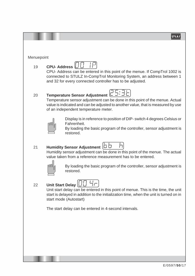
CPU- AddressCPU- Address can be entered in this point of the menue. If CompTrol 1002 isconnected to STULZ In-CompTrol Monitoring System, an address between 1and 32 for every connected controller has to be adjusted.
Temperature Sensor AdjustmentTemperature sensor adjustment can be done in this point of the menue. Actualvalue is indicated and can be adjusted to another value, that is measured by useof an independent temperature meter.
Display is in reference to position of DIP- switch 4 degrees Celsius orFahrenheit.By loading the basic program of the controller, sensor adjustment isrestored.
Humidity Sensor AdjustmentHumidity sensor adjustment can be done in this point of the menue. The actualvalue taken from a reference measurement has to be entered.
By loading the basic program of the controller, sensor adjustment isrestored.
Unit Start DelayUnit start delay can be entered in this point of menue. This is the time, the unitstart is delayed in addition to the initialization time, when the unit is turned on instart mode (Autostart)
The start delay can be entered in 4-second intervals.
Menuepoint
19
20
21
22
E/0597/50 /18
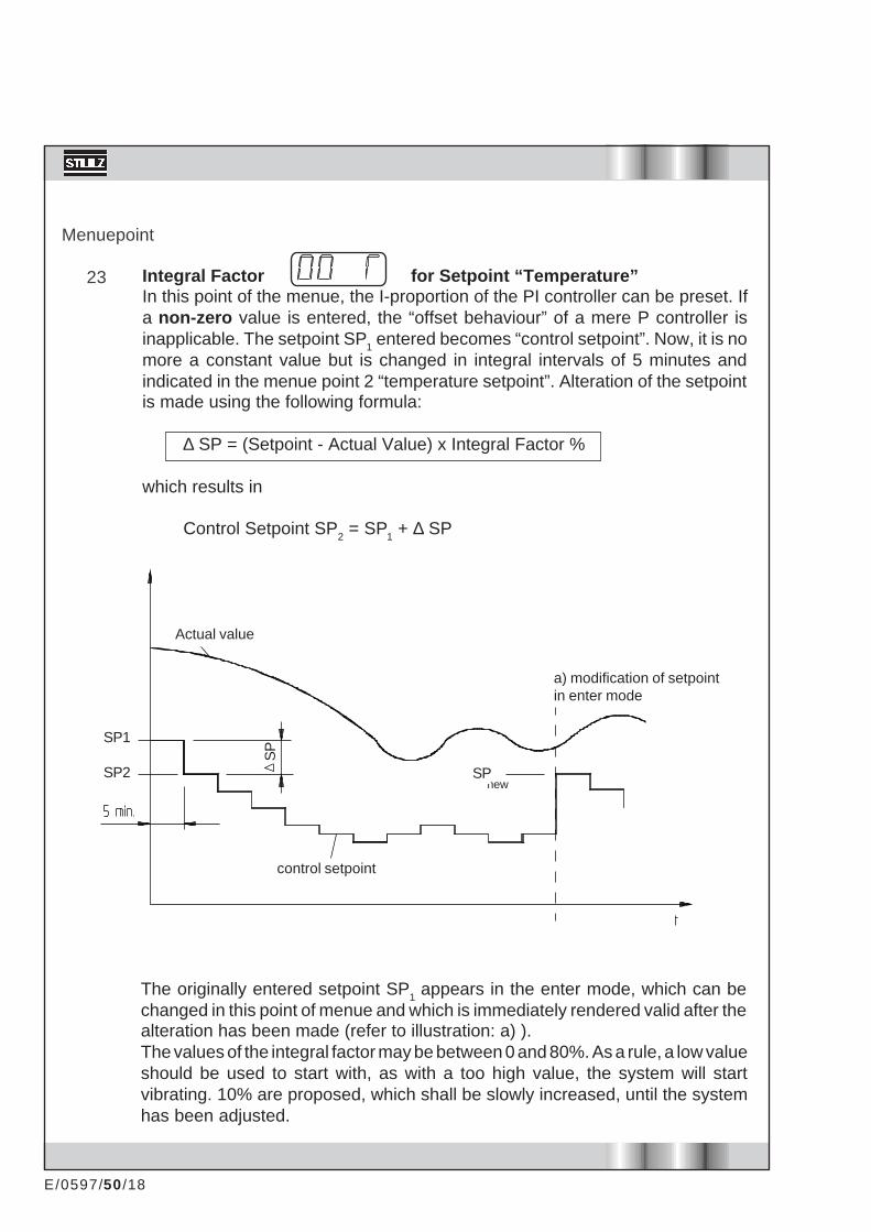
Integral Factor for Setpoint “Temperature”In this point of the menue, the I-proportion of the PI controller can be preset. Ifa non-zero value is entered, the “offset behaviour” of a mere P controller isinapplicable. The setpoint SP1 entered becomes “control setpoint”. Now, it is nomore a constant value but is changed in integral intervals of 5 minutes andindicated in the menue point 2 “temperature setpoint”. Alteration of the setpointis made using the following formula:
∆ SP = (Setpoint - Actual Value) x Integral Factor %
which results in
Control Setpoint SP2 = SP1 + ∆ SP
Menuepoint
23
Actual value
a) modification of setpointin enter mode
control setpoint
new
The originally entered setpoint SP1 appears in the enter mode, which can bechanged in this point of menue and which is immediately rendered valid after thealteration has been made (refer to illustration: a) ).The values of the integral factor may be between 0 and 80%. As a rule, a low valueshould be used to start with, as with a too high value, the system will startvibrating. 10% are proposed, which shall be slowly increased, until the systemhas been adjusted.
SP1
SP2 SP
SP

E/0597/50 /19
Meaning
No sequencing function.Short sequencing 5 min for testing purposes. Innormal mode the remaining minutes till sequencingare shown.Sequencing shown in hours.In the input mode a time lap of 2 to 254 hours canbe chosen. In normal mode the remaining hours tillsequencing are shown.
If "255" is set in the input mode, the unit is markedas the "2nd" unit. No adjustments are carried outon this unit. The sequencing time is only set anddisplayed on the „1st“ unit.
normal mode
05-4-3-2-1
254...1
Un2
input mode
01
2...254
255
For test purposes or in case the I-proportion should be undesirable, the integralfactor is set to zero . A P controller exists and the control setpoint is equal with thesetpoint.
Under the following circumstances, the setpoint is immediately takenover into the control setpoint:
- during initialization phase (make alive)- turning on (start mode)- failure “sensor break-down” active- limiting alarms “temperature” active- modification of setpoint
The range of the control setpoint is limited to setpoint ± 3 K (± 5.4 R).
Sequencing for 2 unitsA 2-unit-sequencing is integrated in the software. The display during input modeand normal mode can vary.
Menuepoint
24
In case of failure (unit 1 or unit 2) the sequencing time is frozen. This state ismaintained until a failure reset is carried out. After that sequencing continues asnormal.

E/0597/50 /20
If unit 1 is the StBy-unit (i.e. the unit, which is not in operation at the moment, dueto the sequencing), a colon („:“) is displayed under menu point „U“. If unit 2 is theStBy-unit the colon disappears.
3K before the alarm „temperature too high“ the StBy-unit starts in addition. Thesequencing time will not be interrupted. At a hysteresis of 3K the unit stops again.
The sequencing uses the standard inputs for remote on/off and water detector/Aux1 and the standard outputs for common alarm and heating 2.If the input Aux1/water detector and/or the output heating 2 is needed, an extensionboard is installed, where one input and output are available for the sequencing.That way the 2nd heating stage and the water detector input are available againon the processor board.
As the sequencing is carried out by using the input for remote on/off, the display ofthe StBy-unit shows:
A connection scheme for both units is shown on the pages 29 and 33.
Menuepoint
25 Actual Operation Level CW ValveIn this menue point, the actual operation level of the CW valve is displayed.This menue point exists only at CW-units.

E/0597/50 /21
GeneralAn alarm or failure is indicated via a short text in the display and status-LED´s.Conditions that activate the alarm-relay are shown in the following table. Each alarm orfailure causes a certain delay, which also can be taken out from the table.Texts for alarms and failures are only shown in operation mode "start", in point of menue1 , and in operation mode "stop". All alarms and failures that have occured up to this timeand corresponding operation- modes are indicated by showing up every four seconds.
WarningsWarnings have no direct influence on the function of the unit, i.e. after a warning hasoccured, the unit can be continued in operation for a while. The alarm relay is not activated.
These functions are only supervised in start mode:- Ultrasonic humidifier (5µS/cm)- filter
AlarmsActual values are supervised not to reach limiting points. After a delay of about 30 secondsthe limiting alarm is activated. Limiting points are supervised even in operation mode "stop".
Alarm "humidity" is only evaluated if dehumidification and humidification hysteresisis not set at "0".
FailuresFailures on the following functions are only supervised in the operation mode "start" :- reheat compressor 1 low pressure- humidification (20µS/cm) compressor 1 low failure- airflow compressor 2 low pressure
compressor 2 low failure
Failures on the following functions are also supervised in the operation mode "stop" .- Aux 1 / water sensor- Aux 2 / firestat and smoke detector- sensor break-down
5. Alarms and Failures

E/0597/50 /22
If the alarm input is supplied with 24V, there is no failure/alarm. If the alarm inputs are notused they have to be supplied with 24V or, if possible, the hysteresis of the function has tobe set to „0“. The inputs concerned are:
Heating 1 and 2Air volume 1 and 2Water sensor/Aux 1 AlarmFire/Aux 2 AlarmHigh pressure, low pressure failure compressorHumidifier alarm / 20 µS/cmAlarm 5 µS/cmFilter alarm
Reset Alarms And FailuresResetting of alarms and failures can only be done in menue point 1.
Warning (Alarm Relay Inactive)
Press key and within 1 s later, press key . After that, warning is reset and thealarm LED disappears.
Alarm + Failure (Alarm Relay Active)
Press key and within 1 s later, press key . The alarm relay is deactivated.
Press key and within 1 s later, press key . All failures indicated are reset and thealarm LED disappears.
In case of a failure reset the components are switched on sequentially (same as afterpower failure), to prevent an overcharge of the alimentation line by the starting current.

E/0597/50 /23
Display
Failures
Alarms
Table of Alarms and Failures
Consequences
------------
------------
------------
------------
reheat 1 and 2
are switched off.
humidifier off.
------------
all compon. off,
valve is closing,
louver is closing.
The alarm "HEA",
"HIP" and "LOP"
are suppressed.
compressor 1 off.
compressor 2 off.
compressor 1 off.
compressor 2 off.
--------------
--------------
--------------
reheat, compressor
off, valve closed.
humidifier off,
dehum. off.
all components off,
valve is closing.
humidifier off.
change controller.
Meaning
room temperature too high
room humidity too low
room temperature too high
room humidity too low
reheat 1 or 2
humidifier (20mS/cm)
conductivity meter (5mS/cm)
airflow module 1
airflow module 2
low pressure compressor 1
low pressure compressor 2
compressor 1 failure
compressor 2 failure
clogged filter
auxiliary alarm 1
auxiliary alarm 2
3°C > T > 50°C
sensor break-down (temp.)
3% > r.h. > 97%
sensor break-down (humidity)
firestat alarm / smoke detector
water alarm
controller defect
Alarm LED
X
X
X
X
X
X
X
X
X
X
X
X
X
X
X
X
X
X
X
X
Alarm Relay
X
X
X
X
X
X
-
X
X
X
X
X
X
-
X
X
X
X
X
X
Time Delay
about 30 s
about 30 s
about 30 s
about 30 s
about 3 s
about 5 min.
about 5 min.
about 20 s
about 20 s
3 min.
3 min.
3 s
3 s
about 5 min.
about 3 s
about 3 s
about 3 s
about 3 s
about 3 s
about 3 s
immediately
12
2
1
21 these failures can be alternatively chosen (DIP-switch 3).after compressor start, otherwise 3 s.3
3

E/0597/50 /24
Numbers refer to the points of menue.
6. Control Scheme for CW-Units
Temperatur Control Scheme
Temperaturetoo low
Temperaturetoo highCW-Cooling
Setpoint
Humidity Control Scheme
Humiditytoo high
SetpointHumiditytoo low Humidification Dehumidification
rel. hum.
Reheat 1Reheat 2

E/0597/50 /25
Control Scheme for Units with Compressor
Temperature Control Scheme
1. Compressor 2. Compressor
Numbers refer to the points of menue.
Temperaturetoo low
Temperaturetoo high
Setpoint
Humidity Control Scheme
Humiditytoo high
SetpointHumiditytoo low Humidification Dehumidification
rel. hum.
Reheat 1Reheat 2

E/0597/50 /26
7. Specification CompTrol 1002
- Technical Data
280 x 195 x 45 mm (11.0" x 7.7" x 1.8")
(24 V + 20 % / - 15 %) V ACX10, X11.1 grounded
12 W
1 Amp
15 V DC, 40 mAmp
2 (0..20 mAmp)
330 Ohm
162 Ohm
4-Digit LED-display4 LED green for status φ 3 mm (1/8")1 LED red for alarm φ 3 mm (1/8")
4 keys
RS 485 9600 Baud
2 x relays 3 Amp, 24 V,1 normally open foralarm, humidification5 x triac 4 Amp, 24 Vfan, valve or compressor and dehumidificationsaver circuit, reheat 1, reheat 2
The consumer is connected to 24V.
8 x 24 V AC2.7 kOhm input resistance
0°C ... 40°C (32°F ... 104°F)
-10°C ... 60°C (14°F ... 140°F)
dimensions l x w x h
power supply
power consumption
fuse
power output
sensor input
working resistance "temperature"
working resistance "humidity"
display
operating panel
interface "Monitoring"
outputs
inputs
operating temperature
storing temperature

E/0597/50 /27
Connection Scheme of Processor Board C1002
24 V~
SensorFan
shut valve / compressor 1
open valve / dehumidification
Reheat 1
Reheat 2 / Sequencing out
Humidifier
Alarm / Sequencing out
Sensor input 0-20mAAirflow 1. moduleFilterReheatHumidification 20µS/cmUltrasonic 5 µS/cm* / high pressure comp. 1Remote On/Off / Sequencing inAux1- Water detector / Sequencing inAux2- Firestat smoke detect* / low press. comp. 1
Monitoring RS 485
Extension card
X10: rack 6.3 • 0.8X11: panel 33 polX12: extender connection 20 pol
TH
LOHI
* If an extension card is installed, the inputs for Ultrasonic 5µS/cm and Aux2/firestat are situatedon the extension card.

E/0597/50 /28
In a CW application, the CompTrol 1002 is usually used for a proportional valve with motordrive. The operation of the control is explained in the following drawing (example for a 150-seconds-runtime).
When connection V+ is supplied with power, the valve is completely opened within 150seconds (operation level 0% to operation level 100%). Shorter times mean steeperoperation level. When connection V- is supplied by power the valve is closing. If there is apower interruption to the valve, the last operation level is fixed.
The consumer is connected to 24V.
Examples:
The function of a triac cannot be checked by means of an electronic continuity tester oran ohmmeter. Measurements provided by these instruments would deliver wrong readingsbecause a triac needs a load for a correct function. For an operational test, a continuity testerwith filament lamp (about 2 W) should be used.
Inputs are designed for 24 V AC, but also a voltage 24V DC can be used.
Valve Contactor
Operationlevel / %

E/0597/50 /29
Connection Scheme for Sequencing at the Processor-Board
20 21 29 30 17
Rem
ote
On/
Off
Aux
1
Hea
ting
2 3
2
1
A1Seq. A2
ALARM
Unit 1
4 2 3 1
24 V 0 V
20 21 29 30 17
3
2
1
A1Seq. A2
ALARM
Unit 2
4 2 3 1
24 V
5
Rem
ote
On/
Off
Aux
1
Hea
ting
2

E/0597/50 /30
Specifications of the Extension Card 1b
Characteristics
With the extension card 1b, additional inputs and outputs are provided to the CompTrol1002. The extension card 1b is fastened to the CompTrol 1002 by means of the two distancepieces enclosed. Electric connection to the basic board is made with a 20-channel plugconnector. As soon as the extension card has been connected, alarms aux 2 / firestat andsmoke detector and Ultrasonic humidifier 5µS/cm are only valid on the extension board.
Operating Elements (DIP Switches 1-6)
DIP-Switch 1 Configuration of a louver
ON: A louver is configured. Fan start is delayed by about 90 s.
OFF: A louver is not configured. The fan starts immediately.
DIP-Switch 2 Configuration of a second compressor.
ON: A second compressor is available. The DIP switchon the rear side of the CompTrol 1002 must be set toOFF (Compressor version).
OFF: A second compressor does not exist.
DIP-Switch 3-6 No function
All DIP switches on the extension card 1b must only be switched when de-energized !

E/0597/50 /31
Function of Extension Card 1b
Compressor Sequencing
If two compressors are configured, these are subject to compressor sequencing, inaccordance with the “first in - first out” principle, i.e. should both compressors be turned on,the compressor that had been turned on first will be turned off first. Start value parameters(menue points 9 and 11) will be changed internally, not visibly, upon each compressor start.
Temperature LimitThe input "Temperature Limit" exists. As soon as a voltage of 24 V is applied to this input,cooling is interrupted.That means for- CW version: The CW valve closes- Compressor version: The compressors are switched off.
125 x 70 x 30 mm (4.9" x 2.8" x 1.2")
(24 + 20 % / - 15 %) V AC
X20.24 grounded
4 W
0.4 AT
6-fold DIP switches
3 x triac (4 A, 24 V) for
louver, compressor 2, sequencing
The consumer is connected to 24 V.
8 x 24 V AC
2.7 kOhm input resistance
0°C ... 40°C (32°F ... 104°F)
-10°C ... 60°C (14°F ... 140°F)
Technical Data Extension Card 1b
Dimensions L x W x H
Power supply
Power consumption
Fuse
Operating elements
Outputs
Inputs
Operating temperature
Storing temperature

E/0597/50 /32
Connection Scheme of the Extension Card 1b
The consumer is connected to 24 V.
Compressor 2
Sequencing outSequencing 24 V
Louver
Sequencing in
high pressure comp.2low pressure comp.2Airflow module 2Temperature limitAux2 / Firestat and smoke detectorUltrasonic 5µS/cm
DIP-Schalter
X20: panel 24 polX21: extender connection 20 pol

E/0597/50 /33
Connection Scheme for Sequencing with Extension Card
20 21 29
3
2
1
A1Seq. A2
ALARM
Unit 1
4 2 3 1
24 V 0 V
20 21 29
3
2
1
A1Seq. A2
ALARM
Unit 2
4 2 3 1
24 V
5
15 11 12
Extension 1b
15 11 12
Extension 1b
Rem
ote
On/
Off
Rem
ote
On/
Off

E/0597/50 /34
2. Setpoint temperature
3. Setpoint humidity
4. Limiting point temperature too high
5. Limiting point temperature too low
6. Limiting point humidity too high
7. Limiting point humidity too low
8a. Valve modulating time
8b. Compressor restart delay
9a. Startpoint cooling
9b. Compressor 1 start
10a. Proportional range (cooling)
10b. Hysteresis compressors
11a. Lifting grade (dehumidification)
11b. Compressor 2 start
12. Start value reheat 1
13. Hysteresis reheat 1 + 2
14. Start value reheat 2
15. Start value humidification
16. Hysteresis humidification
17. Start value dehumidification
18. Hysteresis dehumidification
19. CPU-address
20. Sensor adjustment "temperature"
21. Sensor adjustment "humidity"
22. Unit start delay
23. Integral factor
24. Sequencing for 2 units
10,0...30,0°C
10...90%
10...50°C
0...30°C
30...90%
0...70%
0...255 s
0...255 s
0...9,9 K
0...9,9 K
0...9,9 K
0...9,9 K
0...100%
0...9,9 K
0...9,9 K
0...9,9 K
0...9,9 K
0...20%
0...20%
0...20%
0...20%
1...255
-12,8...+12,7 K
-24...+24%
0...996s
0...80%
0...255
23,0°C
40%
35°C
0°C
80%
0%
150 s
255 s
0,0 K
0,7 K
1,0 K
0,3 K
100%
1,2 K
0,5 K
0,3 K
1,0 K
5%
3%
5%
3%
1
0
0
4
0%
0
Point of Menue RangeStandardvalue Adjusted value
------------------
------------------
Appendix
Standard Programm

E/0597/50 /35
Standard Programm (US)
2. Setpoint temperature
3. Setpoint humidity
4. Limiting point temperature too high
5. Limiting point temperature too low
6. Limiting point humidity too high
7. Limiting point humidity too low
8a. Valve modulating time
8b. Compressor restart delay
9a. Startpoint cooling
9b. Compressor 1 start
10a. Proportional range (cooling)
10b. Hysteresis compressors
11a. Lifting grade (dehumidification)
11b. Compressor 2 start
12. Start value reheat 1
13. Hysteresis reheat 1 + 2
14. Start value reheat 2
15. Start value humidification
16. Hysteresis humidification
17. Start value dehumidification
18. Hysteresis dehumidification
19. CPU-address
20. Sensor adjustment "temperature"
21. Sensor adjustment "humidity"
22. Unit start delay
23. Integral factor
24. Sequencing for 2 units
50...86°F
10...90%
50...122°F
32...86°F
30...90%
0...70%
0...255 s
0...255 s
0..17.8 R
0..17.8 R
0..17.8 R
0..17.8 R
0...100%
0..17.8 R
0..17.8 R
0..17.8 R
0..17.8 R
0...20%
0...20%
0...20%
0...20%
1...255
-23...+22.9 R
-24...+24%
0...996s
0...80%
0...255
75°F
45%
95°F
32°F
80%
0%
150 s
255 s
0R
1.3 R
1.8 R
0.5 R
100%
2.2 R
0.9 R
0.5 R
1.8 R
5%
3%
5%
3%
1
0
0%
4
0%
0
Point of Menue RangeStandardvalue Adjusted value
------------------
------------------

E/0597/50 /36

E/0597/50 /37
Password
In menue points 2 to 24 a password is requested in enter mode. To enter the password, keys and are pressed within 5 seconds.
The display shows
Should a wrong key be pressed or the time be exceeded, entering of password is aborted.

E/0597/50 /38

E/0597/50 /39
You are in the possession of the
TECHNICAL MANUAL FOR CONTROLLER
Index 50 - CompTrol 1002
The following manuals are available for other product ranges:
Index Type of manual
MODULAR LINE
MRD/U A,G,GE 10 Operation InstructionsMRD/U A,G,GE 10PL Planning ManualMRD/U CW 11 Operation InstructionsMRD/U CW 11PL Planning Manual
SMALL A/C UNITS
CCD/U 20 Operation Instructions w Plannning PartDAU 40 CW 21 Operation Instructions
SHELTER A/C UNITS
SAF 101 A (400V) 30 Operation InstructionsSAF 101 A (208/220V) 31 Operation InstructionsSAD 111 A 32 Operation InstructionsPAF 41/71/101 A 33 Operation Instructions
CONTROLLER
C 5000 52 Operation InstructionsInCompTrol 60 Operation InstructionsSequencing box 61 Operation InstructionsTeleCompTrol 62 Operation InstructionsNI Stulz 63 Operation InstructionsSDC - C4000 64 Operation InstructionsGateway Stulz/Honeywell 65 Operation InstructionsSDC - C5000 66 Operation Instructions
CONDENSORS 80 Technical Manual
For further informations please contact our marketing department.
STULZ GmbH - Holsteiner Chaussee 283 - D22457 HamburgTel.: 040/5585-239 Fax: 040/5585-308