aircraft engine structure materials - nato educational notes/rto-en... · told me that they were as...
TRANSCRIPT
Göran Sjöberg
Volvo Aero Corporation, 2008
1. Introduction Some years ago, more specifically 1990, as a newly appointed materials application engineer at GE, Evendale, I met and made friends to some extent with Dr. Stanley Wlodek, well renowned within the superalloy materials field. He was a fountain who brought cold water to a thirsty young doctor-engineer trying to understand how materials application in aircraft engine designs best could be monitored. Early he warned me not to trust design engineers who he considered being to optimistic in their use of design material for aircraft engines. He told me that they were as the farmer in the short story by Dostoyevsky about the farmer and the devil and he asked me if I had read the story but of course I hadn’t and sad to say I have not been able to trace this story later. He told me the following story. The poor farmer met the devil who asked if he wanted more land to his small farm. “Of course!” was the immediate reply and after a while: “How much can I get?” “As much as you want.” – the devil replied. “As much as I want! – what does that mean?” “Well, as much as you can walk around in one day.” The farmer still puzzled scratched his head and asked “When can I start in the morning?” “Well, when the sun rises.” “ And when do I have to be back home?” “Well, when the sun sets.” The farmer after scratching his head a little more asked his final question. “But, if I am not back when the sun sets?” “In that case your soul is mine” was the confident statement by the devil. The outcome was as can be expected that the farmer was to optimistic finally searched for and found far away from home; dead and with his soul with the devil. So the monitoring of materials application in aircraft engines should in principle be done by raising the warning finger to the design engineers and the materials application engineer responsible for that task could belong to a ‘police department’. A designer with liberal attitudes I worked with some years ago finally got so tired of me that he one day after all warning fingers finally exclaimed. “Say something positive for once!” That was a hard blow to take but the project leader was happy with me and told me I was the only one to control the designers. “When you say it is OK to use a material/process we know that it is OK!” Some comfort after all. In the following 20 pages or so I will now try the almost impossible task to intelligibly summarize what is essential for materials application engineering in aircraft engines in general and with a special focus on structures. Due to the strong interest in ultimate performance there will however be a bias towards the hot end of the engine (read superalloys) since engine efficiency for thermodynamic reasons is governed by the resistance of the
RTO-EN-AVT-207 13 - 1
Aircraft Engine Structure Materials
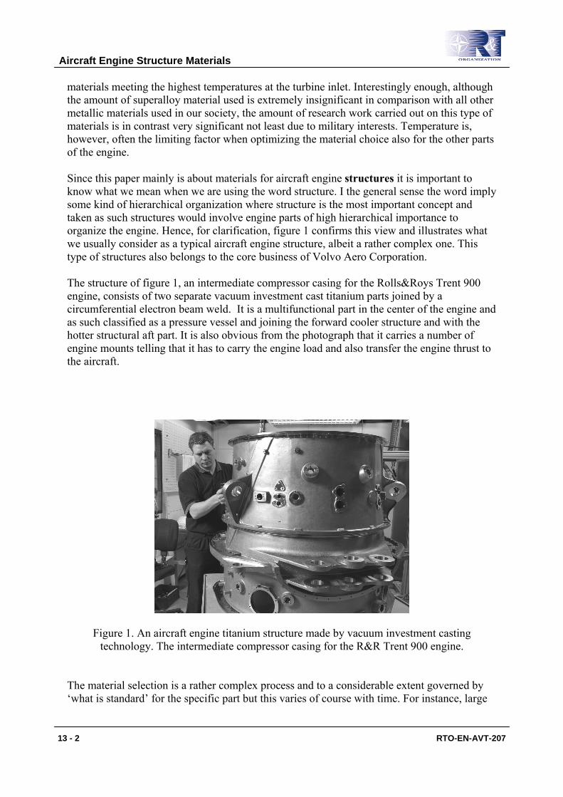
materials meeting the highest temperatures at the turbine inlet. Interestingly enough, although the amount of superalloy material used is extremely insignificant in comparison with all other metallic materials used in our society, the amount of research work carried out on this type of materials is in contrast very significant not least due to military interests. Temperature is, however, often the limiting factor when optimizing the material choice also for the other parts of the engine. Since this paper mainly is about materials for aircraft engine structures it is important to know what we mean when we are using the word structure. I the general sense the word imply some kind of hierarchical organization where structure is the most important concept and taken as such structures would involve engine parts of high hierarchical importance to organize the engine. Hence, for clarification, figure 1 confirms this view and illustrates what we usually consider as a typical aircraft engine structure, albeit a rather complex one. This type of structures also belongs to the core business of Volvo Aero Corporation. The structure of figure 1, an intermediate compressor casing for the Rolls&Roys Trent 900 engine, consists of two separate vacuum investment cast titanium parts joined by a circumferential electron beam weld. It is a multifunctional part in the center of the engine and as such classified as a pressure vessel and joining the forward cooler structure and with the hotter structural aft part. It is also obvious from the photograph that it carries a number of engine mounts telling that it has to carry the engine load and also transfer the engine thrust to the aircraft.
Figure 1. An aircraft engine titanium structure made by vacuum investment casting technology. The intermediate compressor casing for the R&R Trent 900 engine.
The material selection is a rather complex process and to a considerable extent governed by ‘what is standard’ for the specific part but this varies of course with time. For instance, large
Aircraft Engine Structure Materials
13 - 2 RTO-EN-AVT-207
structural parts of the engine were, say fifty years ago, made almost exclusively by manufacturing in the sense that many small pieces from wrought material (sheet material, forgings) were joined first by riveting but later on by inert gas arc welding. Later, around 1980, with the advent of large scale vacuum investment casting technology the possibility of producing very complex geometry with good quality allowed for producing the same multi-component part as a single casting. This technology is today used almost exclusively both for titanium structures in the front end and for superalloy structures in the aft end. As always there are some drawbacks with new technology and in this case there is a weight penalty since cast material in comparison with the same wrought material does have inferior mechanical properties (except possibly for high temperature creep and crack growth) and thicker cast material is therefore often used to compensate for that. More important though is the heavy capital investment necessary for the technology involved, the casting in vacuum, increases very rapidly with the diameter (a square relationship?) of the parts and with the limited number of large aircraft engines using such parts there are few parts to amortize for the investments and there is therefore hardly room for many suppliers. In fact, today, there is an almost monopoly situation for this kind of large size structures with an associated price pattern. And hence, currently, we see a reversed trend, that is a return to manufacturing by welding smaller pieces together. By this, except for the liberation from a single suppliers situation, flexibility is introduced where high strength wrought material can be mixed with small cast parts to be used where the complex geometry is needed. In essence this allows for a weight and cost optimized part – lead time benefits are also possible. Weight is of secondary importance when compared with engine performance but still very, very important everywhere in the engine. So strength over density, specific strength, is a material property of large interest. Here there might also be a chain effect. If, e.g., fan blades are made lighter by the use of carbon fiber composites the rotor where the blades are attached can be made significantly lighter and the surrounding casing may also be made thinner since less material is needed to capture the debris in a blade out event. However, costs involved in such material/application development easily turns astronomical and Rolls-Royce almost went bankrupt after venturing that carbon field for fan blades and finally arrived at using hollow titanium fan blades instead. GE was more successful and uses today this material technology in their GE90 engine. There is a plethora of important technologies which relates to the materials application engineering in aircraft engines which unfortunately not possibly can be covered in an introductory review of this kind rather than very briefly. Such technologies involve the very specialized and sophisticated manufacturing processes necessary in arriving at materials with peak performance, e.g. vacuum metallurgy, single crystal casting and powder metallurgy. Another important field close to this is how to arrive at the ‘premium quality’ material, i.e. material with few and small defects necessary to insure long life not least for the rotating parts and here alternative manufacturing routes as triple vacuum arc melting or electro-slag remelting or even cold hearth melting technologies, where high powered electron or plasma guns, are used for the melting process in actively cooled copper crucibles. Also, but not least, the non destructive evaluation (NDE) is important to make sure that no large defects have survived to finally jeopardize the fatigue properties. Another important materials area which can not be covered here is the surface coating technologies and their applications. There are numerous different coatings used for different purposes in all aircraft engines as i.e. thermal
Aircraft Engine Structure Materials
RTO-EN-AVT-207 13 - 3
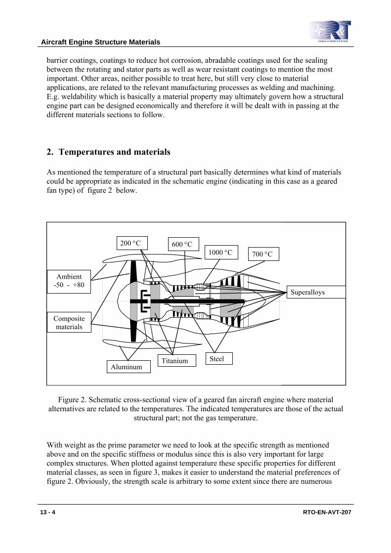
barrier coatings, coatings to reduce hot corrosion, abradable coatings used for the sealing between the rotating and stator parts as well as wear resistant coatings to mention the most important. Other areas, neither possible to treat here, but still very close to material applications, are related to the relevant manufacturing processes as welding and machining. E.g. weldability which is basically a material property may ultimately govern how a structural engine part can be designed economically and therefore it will be dealt with in passing at the different materials sections to follow. 2. Temperatures and materials As mentioned the temperature of a structural part basically determines what kind of materials could be appropriate as indicated in the schematic engine (indicating in this case as a geared fan type) of figure 2 below.
Figure 2. Schematic cross-sectional view of a geared fan aircraft engine where material alternatives are related to the temperatures. The indicated temperatures are those of the actual
structural part; not the gas temperature. With weight as the prime parameter we need to look at the specific strength as mentioned above and on the specific stiffness or modulus since this is also very important for large complex structures. When plotted against temperature these specific properties for different material classes, as seen in figure 3, makes it easier to understand the material preferences of figure 2. Obviously, the strength scale is arbitrary to some extent since there are numerous
600 °C 1000 °C 700 °C
200 °C
Titanium Steel
Superalloys
Aluminum
Composite materials
Ambient -50 - +80
Aircraft Engine Structure Materials
13 - 4 RTO-EN-AVT-207
different alloys belonging to any material class, each with its own strength and temperature characteristics. Before getting into the overview of each material class in the next section of this paper it could be worthwhile to dwell on the comparisons provided by figure 3. Starting at the low temperature end the carbon fiber materials with a polymer matrix (epoxy), often referred to as PMC (Polymer Matrix Composite) material, has a striking specific strength benefit over all other materials mainly due to the strength of the carbon fibres. This advantage makes the use of it almost irresistible notwithstanding the though challenges when designing and not least manufacturing the parts as dearly experienced by Rolls-Royce. E.g. Volvo Aero Corporation recently acquired a company, ACAB, to add competence in this field in order to be able to master the application of this type of materials on the front frames which belong to our specialization. For these huge frames, sometimes larger than 2 m in diameter, as illustrated in figure 5, not only the specific strength is important but also the stiffness due to the very high Young’s modulus of the carbon fibers. In fact the stiffness may be the only real materials parameter which will finally bring such parts into service when the strength limitations imposed by joints and damage in the PCM structures are allowed for in the design reducing the obvious benefits of figure 2. From figure 3 it is also evident why titanium is the second best choice at the lowest temperatures as for the fan blades. It is also understandable why steel finds less and less use in aircraft engines, notably mostly for shaft applications where very high strength maraging steels can be utilized. The properties of aluminum alloys compared with titanium explain why these alloys are rarely used when strength – weight is a main concern. The low temperature capacity of aluminum alloys is also a strong limitation in comparison with titanium. For completeness magnesium alloys should be mentioned since they have a very attractive low density. However, the strength and the elastic modulus are low and temperature restrictions are more severe than for aluminum alloys. Above all, however, there is a galvanic corrosion problem that is difficult, though possible, to account for in design. There is also a fire hazard involved and in summary magnesium alloys have rarely been used for aircraft engine structures and are therefore not included in this review. At higher temperatures the strength of the epoxy polymer matrix rapidly declines leaving the titanium alloys without competition except for the superalloys who are gaining in importance with increasing temperatures. At above approximately 500 °C where most of the strength disappears from the titanium alloys superalloy materials must be chosen for the structural parts. Since steels, mainly stainless 12 % chromium steels like Greek Ascoly, are much less costly and may be used where the lower strength can be compensated for and below 600 °C they may serve as alternatives if cost is of prime importance. With increasing engine temperatures less and less steel is today found in hot structural parts of aircraft engines. Above 600 °C there are no rivals to superalloys as material for structures. For turbine blade applications titanium aluminides are though now finding first applications, e.g. in the two last stages of the GEnx engine. As mentioned in the introduction there is a dual benefit of having a light weight blade design, less stress on the rotating part and lower requirements on the external structure from a blade out point of view and as a result lower weight on both parts. I addition the brittleness of the titanium aluminides is here also a benefit since less havoc is
Aircraft Engine Structure Materials
RTO-EN-AVT-207 13 - 5
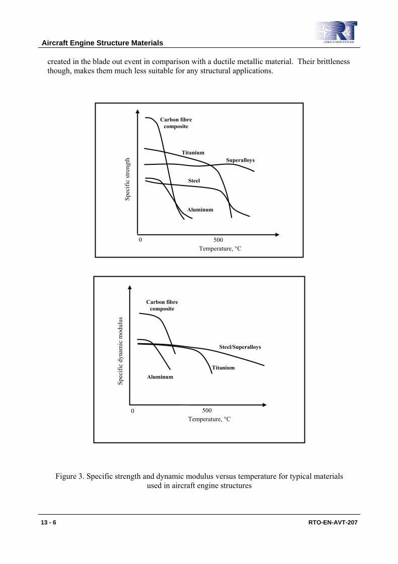
created in the blade out event in comparison with a ductile metallic material. Their brittleness though, makes them much less suitable for any structural applications.
Figure 3. Specific strength and dynamic modulus versus temperature for typical materials used in aircraft engine structures
Temperature, °C
Spec
ific
dyna
mic
mod
ulus
0 500
Carbon fibre composite
Titanium Aluminum
Steel/Superalloys
Temperature, °C
Spec
ific
stre
ngth
0 500
Carbon fibre composite
Titanium
Steel
Aluminum
Superalloys
Aircraft Engine Structure Materials
13 - 6 RTO-EN-AVT-207
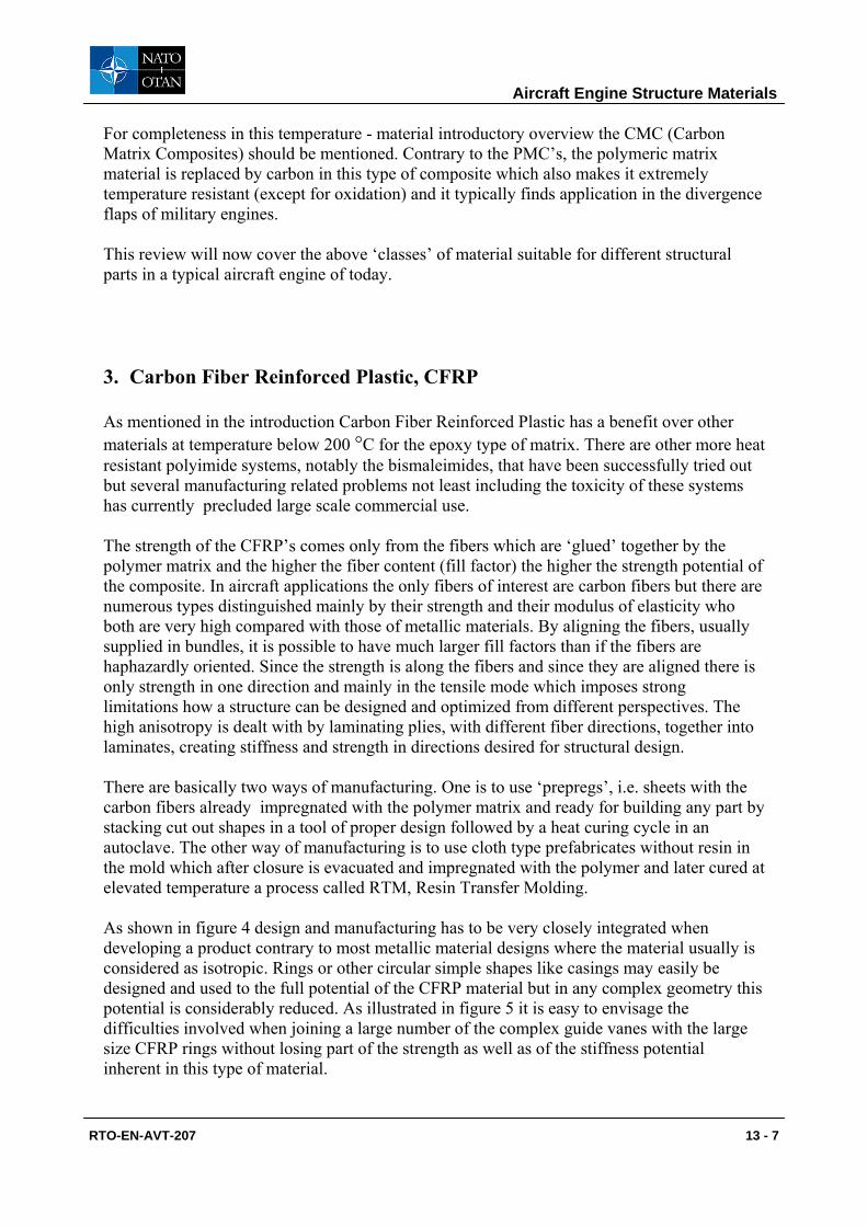
For completeness in this temperature - material introductory overview the CMC (Carbon Matrix Composites) should be mentioned. Contrary to the PMC’s, the polymeric matrix material is replaced by carbon in this type of composite which also makes it extremely temperature resistant (except for oxidation) and it typically finds application in the divergence flaps of military engines. This review will now cover the above ‘classes’ of material suitable for different structural parts in a typical aircraft engine of today. 3. Carbon Fiber Reinforced Plastic, CFRP As mentioned in the introduction Carbon Fiber Reinforced Plastic has a benefit over other materials at temperature below 200 °C for the epoxy type of matrix. There are other more heat resistant polyimide systems, notably the bismaleimides, that have been successfully tried out but several manufacturing related problems not least including the toxicity of these systems has currently precluded large scale commercial use. The strength of the CFRP’s comes only from the fibers which are ‘glued’ together by the polymer matrix and the higher the fiber content (fill factor) the higher the strength potential of the composite. In aircraft applications the only fibers of interest are carbon fibers but there are numerous types distinguished mainly by their strength and their modulus of elasticity who both are very high compared with those of metallic materials. By aligning the fibers, usually supplied in bundles, it is possible to have much larger fill factors than if the fibers are haphazardly oriented. Since the strength is along the fibers and since they are aligned there is only strength in one direction and mainly in the tensile mode which imposes strong limitations how a structure can be designed and optimized from different perspectives. The high anisotropy is dealt with by laminating plies, with different fiber directions, together into laminates, creating stiffness and strength in directions desired for structural design. There are basically two ways of manufacturing. One is to use ‘prepregs’, i.e. sheets with the carbon fibers already impregnated with the polymer matrix and ready for building any part by stacking cut out shapes in a tool of proper design followed by a heat curing cycle in an autoclave. The other way of manufacturing is to use cloth type prefabricates without resin in the mold which after closure is evacuated and impregnated with the polymer and later cured at elevated temperature a process called RTM, Resin Transfer Molding. As shown in figure 4 design and manufacturing has to be very closely integrated when developing a product contrary to most metallic material designs where the material usually is considered as isotropic. Rings or other circular simple shapes like casings may easily be designed and used to the full potential of the CFRP material but in any complex geometry this potential is considerably reduced. As illustrated in figure 5 it is easy to envisage the difficulties involved when joining a large number of the complex guide vanes with the large size CFRP rings without losing part of the strength as well as of the stiffness potential inherent in this type of material.
Aircraft Engine Structure Materials
RTO-EN-AVT-207 13 - 7
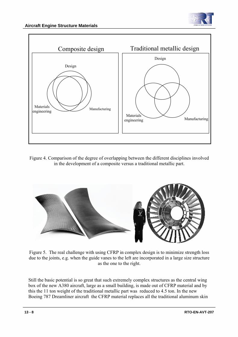
Figure 4. Comparison of the degree of overlapping between the different disciplines involved
in the development of a composite versus a traditional metallic part.
Figure 5. The real challenge with using CFRP in complex design is to minimize strength loss due to the joints, e.g. when the guide vanes to the left are incorporated in a large size structure
as the one to the right. Still the basic potential is so great that such extremely complex structures as the central wing box of the new A380 aircraft, large as a small building, is made out of CFRP material and by this the 11 ton weight of the traditional metallic part was reduced to 4.5 ton. In the new Boeing 787 Dreamliner aircraft the CFRP material replaces all the traditional aluminum skin
Design
Manufacturing
Design
Materials engineering
Composite design Traditional metallic design
Materials engineering
Manufacturing
Aircraft Engine Structure Materials
13 - 8 RTO-EN-AVT-207
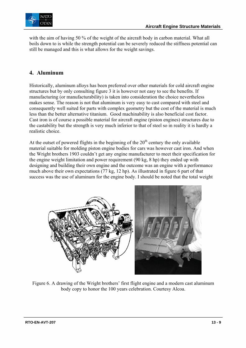
with the aim of having 50 % of the weight of the aircraft body in carbon material. What all boils down to is while the strength potential can be severely reduced the stiffness potential can still be managed and this is what allows for the weight savings. 4. Aluminum Historically, aluminum alloys has been preferred over other materials for cold aircraft engine structures but by only consulting figure 3 it is however not easy to see the benefits. If manufacturing (or manufacturability) is taken into consideration the choice nevertheless makes sense. The reason is not that aluminum is very easy to cast compared with steel and consequently well suited for parts with complex geometry but the cost of the material is much less than the better alternative titanium. Good machinability is also beneficial cost factor. Cast iron is of course a possible material for aircraft engine (piston engines) structures due to the castability but the strength is very much inferior to that of steel so in reality it is hardly a realistic choice. At the outset of powered flights in the beginning of the 20th century the only available material suitable for molding piston engine bodies for cars was however cast iron. And when the Wright brothers 1903 couldn’t get any engine manufacturer to meet their specification for the engine weight limitation and power requirement (90 kg, 8 hp) they ended up with designing and building their own engine and the outcome was an engine with a performance much above their own expectations (77 kg, 12 hp). As illustrated in figure 6 part of that success was the use of aluminum for the engine body. I should be noted that the total weight
Figure 6. A drawing of the Wright brothers’ first flight engine and a modern cast aluminum body copy to honor the 100 years celebration. Courtesy Alcoa.
Aircraft Engine Structure Materials
RTO-EN-AVT-207 13 - 9
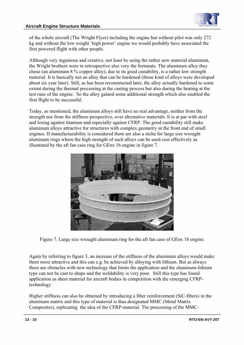
of the whole aircraft (The Wright Flyer) including the engine but without pilot was only 272 kg and without the low weight ‘high power’ engine we would probably have associated the first powered flight with other people. Although very ingenious and creative, not least by using the rather new material aluminum, the Wright brothers were in retrospective also very the fortunate. The aluminum alloy they chose (an aluminum 8 % copper alloy), due to its good castability, is a rather low strength material. It is basically not an alloy that can be hardened (those kind of alloys were developed about six year later). Still, as has been reconstructed later, the alloy actually hardened to some extent during the thermal processing at the casting process but also during the heating at the test runs of the engine. So the alloy gained some additional strength which also enabled the first flight to be successful. Today, as mentioned, the aluminum alloys still have no real advantage, neither from the strength nor from the stiffness perspective, over alternative materials. It is at par with steel and losing against titanium and especially against CFRP. The good castability still make aluminum alloys attractive for structures with complex geometry in the front end of small engines. If manufacturability is considered there are also a niche for large size wrought aluminum rings where the high strength of such alloys can be used cost effectively as illustrated by the aft fan case ring for GEnx 1b engine in figure 7.
Figure 7. Large size wrought aluminum ring for the aft fan case of GEnx 1b engine. Again by referring to figure 3, an increase of the stiffness of the aluminum alloys would make them more attractive and this can e.g. be achieved by alloying with lithium. But as always there are obstacles with new technology that limits the application and the aluminum-lithium type can not be cast to shape and the weldability is very poor. Still this type has found application as sheet material for aircraft bodies in competition with the emerging CFRP-technology. Higher stiffness can also be obtained by introducing a fiber reinforcement (SiC-fibers) in the aluminum matrix and this type of material is thus designated MMC (Metal Matrix Composites), replicating the idea of the CFRP-material. The processing of the MMC-
Aircraft Engine Structure Materials
13 - 10 RTO-EN-AVT-207
materials imposes even more severe restrictions to possible applications. In total titanium with its superior properties in comparison, although being a high cost material, might therefore be a better alternative. 5. Titanium The high specific strength of titanium alloys, over a wide temperature range, make them very attractive for general aerospace applications and not least for rotors but also for structures. The outstandingly good corrosion properties also make titanium very attractive for the chemical and food industry. Since titanium chemically is an extremely reactive metal it bonds very strongly with oxygen and it is as titanium oxide it is found in nature and there are in fact ample supplies of this mineral. Inherently it is therefore also very difficult to separate the metal from the oxide and as a consequence the metallurgical processing is complex and then very expensive. All production today is by the Kroll process developed already 1936 but not really industrial until 1956. Efforts are made to find alternative cheaper methods but today there are no serious alternatives to consider in the short term but the Armstrong process seems to be an interesting candidate in the longer run. As a part of the total metallurgical industry the titanium business is very small with about a 100,000 tonnes/year production capacity world wide and with only about 10 % in the US. Even if only a part of the production is good enough for the aerospace industry it is still this industry which sets the price levels on the market. During the cold war, back in the fifties, production capacities were built up by government funding for defense purpose and the production was not basically intended for the commercial market. When the arms race slowed down the military demand on titanium diminished with overcapacity and commercial titanium prices that hardly covered the running cost of the plants and several were mothballed. With the artificially low prices titanium has merged its way into many new areas of applications and the old surplus capacity has now finally been used up and the prices on titanium have also dramatically increased during the last few years. Although prices varies regularly with the ups and downs of the aerospace industry the investors now firmly believe that the market will be more stable due to the increasing demands from these other sectors and large scale investments made in new production sites, based on the same Kroll process, will properly amortize. By the Kroll process of today typically 10 tons titanium ‘sponge’ ingots are produced. They are not solid but porous as the name indicates and also with a material quality that varies across the ingots. By mechanically breaking the ingot into pieces the good aerospace quality material is separated from the material to be used for less demanding applications. Due to the reactive nature of the titanium it is not possible to improve the basic quality of the titanium by subsequent metallurgical processing, ‘metallurgical cleaning’, as is the case with more common metallic design materials as stainless steels. Still, some ‘trapping’ of deleterious impurities can be achieved during the further processing – especially for rotating grades this is extremely important. To produce solid material from the sponge it has to be melted by an electric arc or even an electron or plasma beam process which all must be carried out in
Aircraft Engine Structure Materials
RTO-EN-AVT-207 13 - 11
vacuum or argon. This is a complex process involving many steps in the arc electrode preparation and in the melting under very controlled conditions. During the melting step the aerospace titanium is also alloyed with a range of different elements to produce a number of different alloys of different properties of which the most used is the Ti-6-4 (Ti-6Al-4V). An important characteristic of titanium-base materials is the reversible transformation of the crystal structure from alpha (α, hexagonal close-packed) structure to beta (β, body-centered cubic) structure when the temperatures exceed certain level. This allotropic behavior, which depends on the type and amount of alloy contents, allows complex variations in microstructure and more diverse strengthening opportunities than those of other nonferrous alloys such as copper or aluminum. By alloying, the character, in terms of the α/ β - ratio, can be adjusted to allow for special properties by the processing.
Other alloys of interest for aerospace are Ti-5Al-2Sn-2Zr-4Mo-4Cr (commonly called Ti-17) and Ti-6Al-2Sn-4Zr-6Mo for high strength in heavy sections at elevated temperatures and Ti-6242 (Ti-6Al-2Sn-4Zr-2Mo) for creep resistance.
Of special interest for aircraft engine structures is the development of the large size vacuum investment casting technology during the eighties, notably by PCC in Portland. This enabled the very ancient lost wax process to be used also for the titanium alloys. Certain features are here involved. As with superalloys all melts must be protected from the atmosphere, i.e. not only the melting of the material to be cast must be done in vacuum but also the actual pouring of the melt into the investment casting mold has to be carried out in a vacuum chamber. This process will be described in a little more in the section about superalloys. What is special with titanium in comparison with superalloys is that the metal chemically reacts with the ceramic investment shell material – there are no known shell that can eliminate this problem. A very thin skin (a fraction of a millimeter) of the casting is therefore contaminated with oxygen. The oxygen absorbed in the metal stabilizes the α -phase and this is then called α -case layer which is very brittle and easily cracks. This is of course unacceptable and the layer must be removed by a chemical milling operation. That is, the casting is submerged in a very vicious acid bath – remember the material is very corrosion resistant – for a specific long enough period of time to remove the α -case layer.
Inherent in the process of casting complex geometries is the fact that the material is not mechanically (plastically) worked – wrought – afterwards. In wrought material the plastic work imposed e.g. by forging on the cast ingots improves the homogeneity of the material and closes internal voids and breaks up impurities into smaller fragments which makes them less harmful. Not least important is that the grain size may be refined through recrystallization in the wrought material. In essence, all mechanical properties of wrought material are therefore much better than those of the material as cast. But there are also ways of improving the quality of large size structural castings as the one shown in figure 1 or the one below in figure 8. First of all a homogenization heat treatment of the as cast material is carried out at the highest possible temperatures by which some of the uneven distribution of the alloying elements (due to what is called segregation) is reduced. Obvious defects detected by the naked eye, fluorescent penetrant or by x-ray inspection are subject to weld repair if possible. Since basically all large structural casting have defects in need of repair they would all be scrapped if weld repair was not possible to carry out. For
Aircraft Engine Structure Materials
13 - 12 RTO-EN-AVT-207
titanium alloys which are very reactive it is then important to use a very clean protective inert argon atmosphere during the welding and this is routinely done.
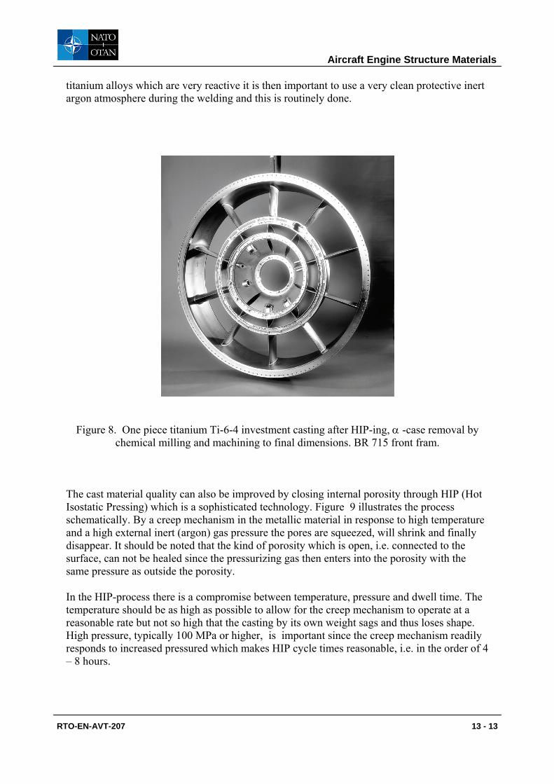
Figure 8. One piece titanium Ti-6-4 investment casting after HIP-ing, α -case removal by chemical milling and machining to final dimensions. BR 715 front fram.
The cast material quality can also be improved by closing internal porosity through HIP (Hot Isostatic Pressing) which is a sophisticated technology. Figure 9 illustrates the process schematically. By a creep mechanism in the metallic material in response to high temperature and a high external inert (argon) gas pressure the pores are squeezed, will shrink and finally disappear. It should be noted that the kind of porosity which is open, i.e. connected to the surface, can not be healed since the pressurizing gas then enters into the porosity with the same pressure as outside the porosity. In the HIP-process there is a compromise between temperature, pressure and dwell time. The temperature should be as high as possible to allow for the creep mechanism to operate at a reasonable rate but not so high that the casting by its own weight sags and thus loses shape. High pressure, typically 100 MPa or higher, is important since the creep mechanism readily responds to increased pressured which makes HIP cycle times reasonable, i.e. in the order of 4 – 8 hours.
Aircraft Engine Structure Materials
RTO-EN-AVT-207 13 - 13
As may be imagined the HIP technology is expensive and the cost of the equipment increases rapidly with the diameter of the parts to be processed; in fact there is in principle a square relationship. For all cast structural aerospace parts it is however deemed necessary to use the process. For the very largest diameter parts (> 1.7 m) there are today no HIP equipment available and it is questionable if there is a market for the large size vessels necessary to treat such parts considering the limited number manufactured. Alternatively such parts may be split in three sections and later, after HIP, be joined to make the full part. Still there is a ‘giga-HIP’ which is scheduled for installation in 2009 at Kinzoku Giken's Himeji factory in Japan. The working zone diameter will be 2 m. The same type of cost arguments also relates to the equipment used for the actual investment casting process in all steps as already mentioned in the introduction to this paper.
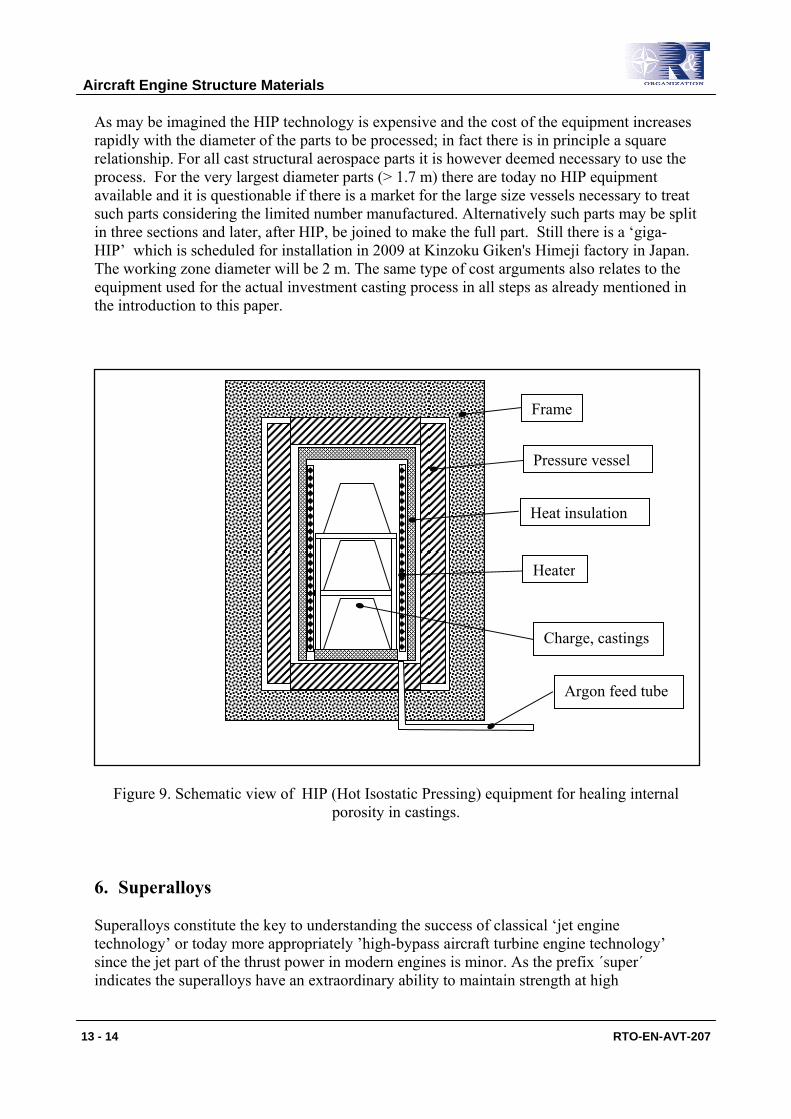
Figure 9. Schematic view of HIP (Hot Isostatic Pressing) equipment for healing internal porosity in castings.
6. Superalloys Superalloys constitute the key to understanding the success of classical ‘jet engine technology’ or today more appropriately ’high-bypass aircraft turbine engine technology’ since the jet part of the thrust power in modern engines is minor. As the prefix ´super´ indicates the superalloys have an extraordinary ability to maintain strength at high
Frame
Pressure vessel
Heat insulation
Heater
Charge, castings
Argon feed tube
Aircraft Engine Structure Materials
13 - 14 RTO-EN-AVT-207
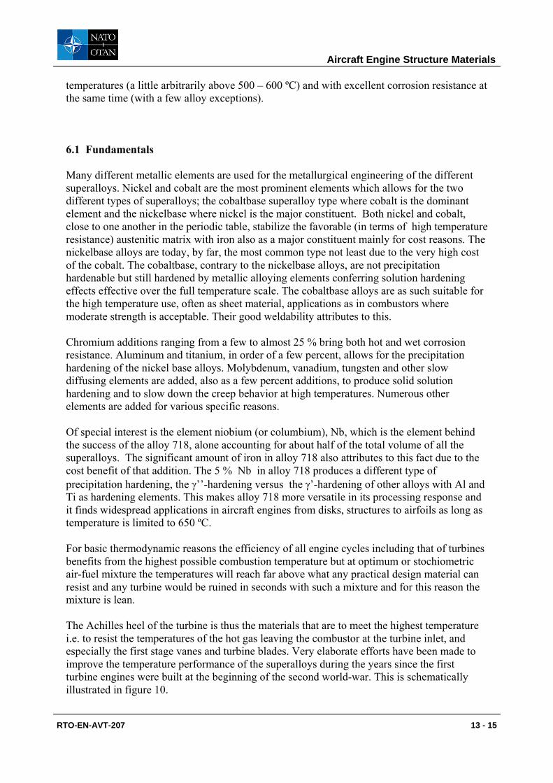
temperatures (a little arbitrarily above 500 – 600 ºC) and with excellent corrosion resistance at the same time (with a few alloy exceptions). 6.1 Fundamentals Many different metallic elements are used for the metallurgical engineering of the different superalloys. Nickel and cobalt are the most prominent elements which allows for the two different types of superalloys; the cobaltbase superalloy type where cobalt is the dominant element and the nickelbase where nickel is the major constituent. Both nickel and cobalt, close to one another in the periodic table, stabilize the favorable (in terms of high temperature resistance) austenitic matrix with iron also as a major constituent mainly for cost reasons. The nickelbase alloys are today, by far, the most common type not least due to the very high cost of the cobalt. The cobaltbase, contrary to the nickelbase alloys, are not precipitation hardenable but still hardened by metallic alloying elements conferring solution hardening effects effective over the full temperature scale. The cobaltbase alloys are as such suitable for the high temperature use, often as sheet material, applications as in combustors where moderate strength is acceptable. Their good weldability attributes to this. Chromium additions ranging from a few to almost 25 % bring both hot and wet corrosion resistance. Aluminum and titanium, in order of a few percent, allows for the precipitation hardening of the nickel base alloys. Molybdenum, vanadium, tungsten and other slow diffusing elements are added, also as a few percent additions, to produce solid solution hardening and to slow down the creep behavior at high temperatures. Numerous other elements are added for various specific reasons. Of special interest is the element niobium (or columbium), Nb, which is the element behind the success of the alloy 718, alone accounting for about half of the total volume of all the superalloys. The significant amount of iron in alloy 718 also attributes to this fact due to the cost benefit of that addition. The 5 % Nb in alloy 718 produces a different type of precipitation hardening, the γ’’-hardening versus the γ’-hardening of other alloys with Al and Ti as hardening elements. This makes alloy 718 more versatile in its processing response and it finds widespread applications in aircraft engines from disks, structures to airfoils as long as temperature is limited to 650 ºC. For basic thermodynamic reasons the efficiency of all engine cycles including that of turbines benefits from the highest possible combustion temperature but at optimum or stochiometric air-fuel mixture the temperatures will reach far above what any practical design material can resist and any turbine would be ruined in seconds with such a mixture and for this reason the mixture is lean. The Achilles heel of the turbine is thus the materials that are to meet the highest temperature i.e. to resist the temperatures of the hot gas leaving the combustor at the turbine inlet, and especially the first stage vanes and turbine blades. Very elaborate efforts have been made to improve the temperature performance of the superalloys during the years since the first turbine engines were built at the beginning of the second world-war. This is schematically illustrated in figure 10.
Aircraft Engine Structure Materials
RTO-EN-AVT-207 13 - 15
A precursor to this development was the efforts done to improve the performance of the military piston aircraft engines with powerful turbochargers necessary for flight operations at high altitudes. The poor heat resistance of the material in the airfoils of the turbine was also here the tumble stone. By a historical coincidence it was overcome through a company who had developed the lost wax investment casting process to produce dental prosthesis of
Figure 10. Improvements of airfoil and turbine blade superalloy temperature resistance by alloy and process development in combination.
complex shape and from a cobalt base alloy, Vitallium, and both the process and the alloy proved successful for the turbine blades in the GE turbocharger. One of the 35 million foils produced (throughout the war) is shown in figure 11 together with a typical modern investment casting ‘tree’ used to produce turbine blades by Howmet Corporation, a leading company for investment casting of superalloys.
2000 1950 1970
700
1000
1200
Year
Tem
pera
ture
, ºC
Mainly wrought materials
Directional and singel crystal casting
Vacuum metallurgy and investment casting
Aircraft Engine Structure Materials
13 - 16 RTO-EN-AVT-207
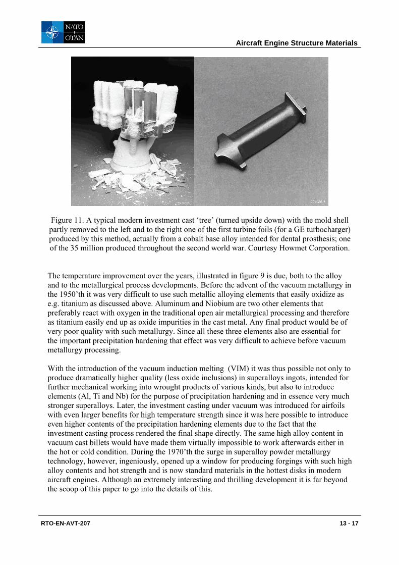
Figure 11. A typical modern investment cast ‘tree’ (turned upside down) with the mold shell partly removed to the left and to the right one of the first turbine foils (for a GE turbocharger) produced by this method, actually from a cobalt base alloy intended for dental prosthesis; one of the 35 million produced throughout the second world war. Courtesy Howmet Corporation.
The temperature improvement over the years, illustrated in figure 9 is due, both to the alloy and to the metallurgical process developments. Before the advent of the vacuum metallurgy in the 1950’th it was very difficult to use such metallic alloying elements that easily oxidize as e.g. titanium as discussed above. Aluminum and Niobium are two other elements that preferably react with oxygen in the traditional open air metallurgical processing and therefore as titanium easily end up as oxide impurities in the cast metal. Any final product would be of very poor quality with such metallurgy. Since all these three elements also are essential for the important precipitation hardening that effect was very difficult to achieve before vacuum metallurgy processing. With the introduction of the vacuum induction melting (VIM) it was thus possible not only to produce dramatically higher quality (less oxide inclusions) in superalloys ingots, intended for further mechanical working into wrought products of various kinds, but also to introduce elements (Al, Ti and Nb) for the purpose of precipitation hardening and in essence very much stronger superalloys. Later, the investment casting under vacuum was introduced for airfoils with even larger benefits for high temperature strength since it was here possible to introduce even higher contents of the precipitation hardening elements due to the fact that the investment casting process rendered the final shape directly. The same high alloy content in vacuum cast billets would have made them virtually impossible to work afterwards either in the hot or cold condition. During the 1970’th the surge in superalloy powder metallurgy technology, however, ingeniously, opened up a window for producing forgings with such high alloy contents and hot strength and is now standard materials in the hottest disks in modern aircraft engines. Although an extremely interesting and thrilling development it is far beyond the scoop of this paper to go into the details of this.
Aircraft Engine Structure Materials
RTO-EN-AVT-207 13 - 17
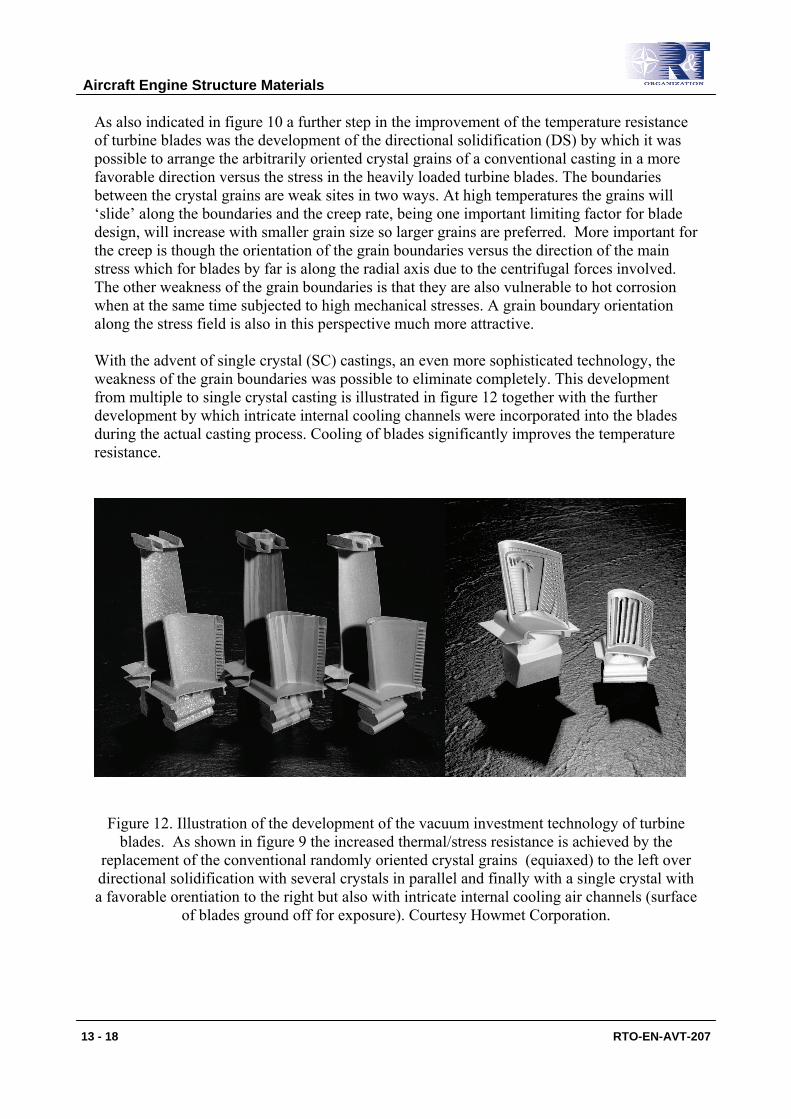
As also indicated in figure 10 a further step in the improvement of the temperature resistance of turbine blades was the development of the directional solidification (DS) by which it was possible to arrange the arbitrarily oriented crystal grains of a conventional casting in a more favorable direction versus the stress in the heavily loaded turbine blades. The boundaries between the crystal grains are weak sites in two ways. At high temperatures the grains will ‘slide’ along the boundaries and the creep rate, being one important limiting factor for blade design, will increase with smaller grain size so larger grains are preferred. More important for the creep is though the orientation of the grain boundaries versus the direction of the main stress which for blades by far is along the radial axis due to the centrifugal forces involved. The other weakness of the grain boundaries is that they are also vulnerable to hot corrosion when at the same time subjected to high mechanical stresses. A grain boundary orientation along the stress field is also in this perspective much more attractive. With the advent of single crystal (SC) castings, an even more sophisticated technology, the weakness of the grain boundaries was possible to eliminate completely. This development from multiple to single crystal casting is illustrated in figure 12 together with the further development by which intricate internal cooling channels were incorporated into the blades during the actual casting process. Cooling of blades significantly improves the temperature resistance.
Figure 12. Illustration of the development of the vacuum investment technology of turbine blades. As shown in figure 9 the increased thermal/stress resistance is achieved by the
replacement of the conventional randomly oriented crystal grains (equiaxed) to the left over directional solidification with several crystals in parallel and finally with a single crystal with a favorable orentiation to the right but also with intricate internal cooling air channels (surface
of blades ground off for exposure). Courtesy Howmet Corporation.
Aircraft Engine Structure Materials
13 - 18 RTO-EN-AVT-207
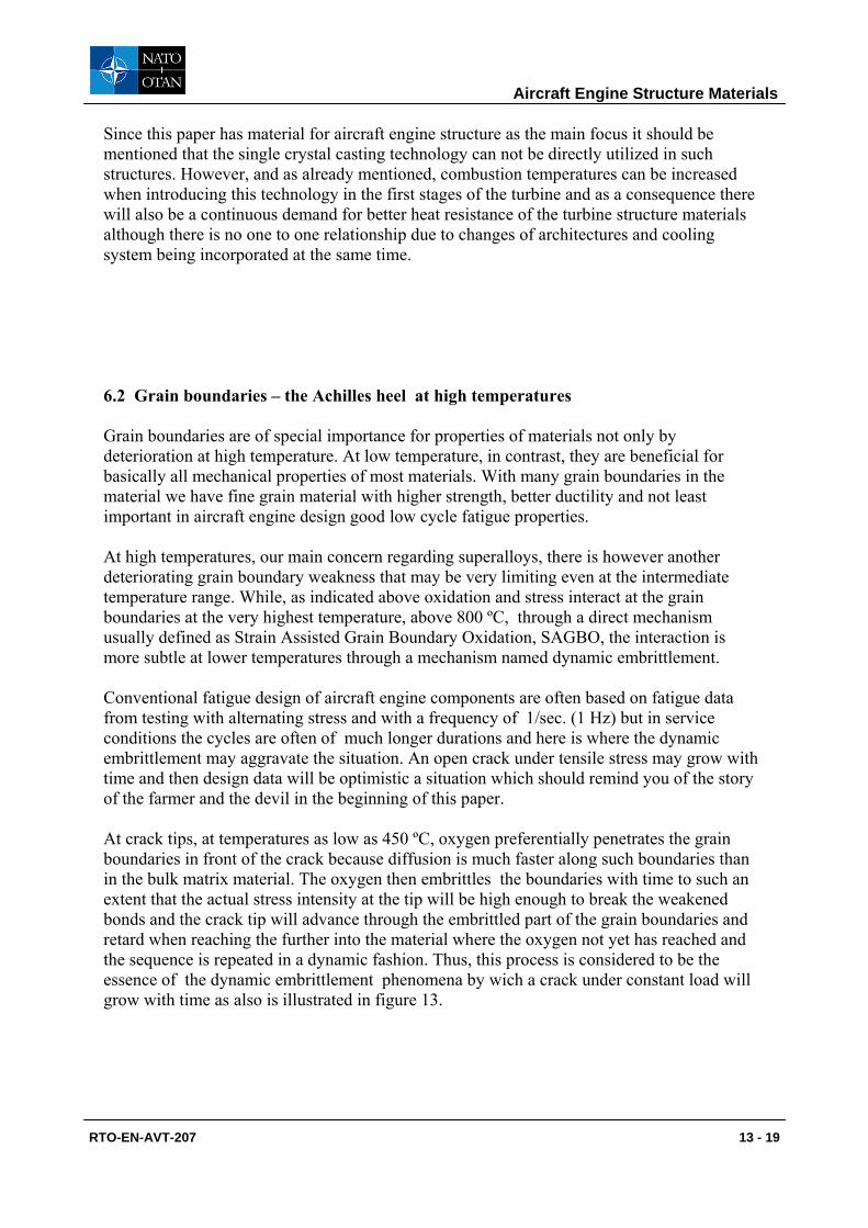
Since this paper has material for aircraft engine structure as the main focus it should be mentioned that the single crystal casting technology can not be directly utilized in such structures. However, and as already mentioned, combustion temperatures can be increased when introducing this technology in the first stages of the turbine and as a consequence there will also be a continuous demand for better heat resistance of the turbine structure materials although there is no one to one relationship due to changes of architectures and cooling system being incorporated at the same time. 6.2 Grain boundaries – the Achilles heel at high temperatures Grain boundaries are of special importance for properties of materials not only by deterioration at high temperature. At low temperature, in contrast, they are beneficial for basically all mechanical properties of most materials. With many grain boundaries in the material we have fine grain material with higher strength, better ductility and not least important in aircraft engine design good low cycle fatigue properties. At high temperatures, our main concern regarding superalloys, there is however another deteriorating grain boundary weakness that may be very limiting even at the intermediate temperature range. While, as indicated above oxidation and stress interact at the grain boundaries at the very highest temperature, above 800 ºC, through a direct mechanism usually defined as Strain Assisted Grain Boundary Oxidation, SAGBO, the interaction is more subtle at lower temperatures through a mechanism named dynamic embrittlement. Conventional fatigue design of aircraft engine components are often based on fatigue data from testing with alternating stress and with a frequency of 1/sec. (1 Hz) but in service conditions the cycles are often of much longer durations and here is where the dynamic embrittlement may aggravate the situation. An open crack under tensile stress may grow with time and then design data will be optimistic a situation which should remind you of the story of the farmer and the devil in the beginning of this paper. At crack tips, at temperatures as low as 450 ºC, oxygen preferentially penetrates the grain boundaries in front of the crack because diffusion is much faster along such boundaries than in the bulk matrix material. The oxygen then embrittles the boundaries with time to such an extent that the actual stress intensity at the tip will be high enough to break the weakened bonds and the crack tip will advance through the embrittled part of the grain boundaries and retard when reaching the further into the material where the oxygen not yet has reached and the sequence is repeated in a dynamic fashion. Thus, this process is considered to be the essence of the dynamic embrittlement phenomena by wich a crack under constant load will grow with time as also is illustrated in figure 13.
Aircraft Engine Structure Materials
RTO-EN-AVT-207 13 - 19
Figure 13. The dynamic embrittlement process schematically. At intermediate high temperatures oxygen penetrates grain boundaries at a crack tip and make the crack grow under
constant load in an intermittent way. 6.3 Hot superalloy structures There are two fundamental features involved in the shaping of superalloys into the desired structural geometry as mentioned earlier. Either geometry can be brought by plastic work, by e.g. forging or rolling, or brought by the casting process. As also has been mentioned earlier in this paper the optimizing of structures for light weight, which is the hall mark of the Volvo Aero Corporation of today, is paramount to master all relevant materials technologies at disposal. Alloy 718 is the most widely used superalloy material, for reasons mentioned above, and in hot structures it is used either as castings or as wrought material or in combination. In figure 14 two alloy 718 structures of the combination type are shown. The compressor rear frame for the GE CF6 engine at the top is in essence a one piece casting where wrought rings are electron beam (EB) welded to the front (the smaller diameter end facing the compressor) and to the aft end (the large diameter end facing the turbine part of the engine). Due to the poor strength of castings in comparison with wrought material, especially in thick cross sections with large grains, the replacement with thinner, high strength wrought rings, allows for significant but still limited weight savings on a structure like this. At the lower part of figure
Stress field at crack tip
Oxygen diffusion
Crack advance
Oxygen diffusion
Aircraft Engine Structure Materials
13 - 20 RTO-EN-AVT-207
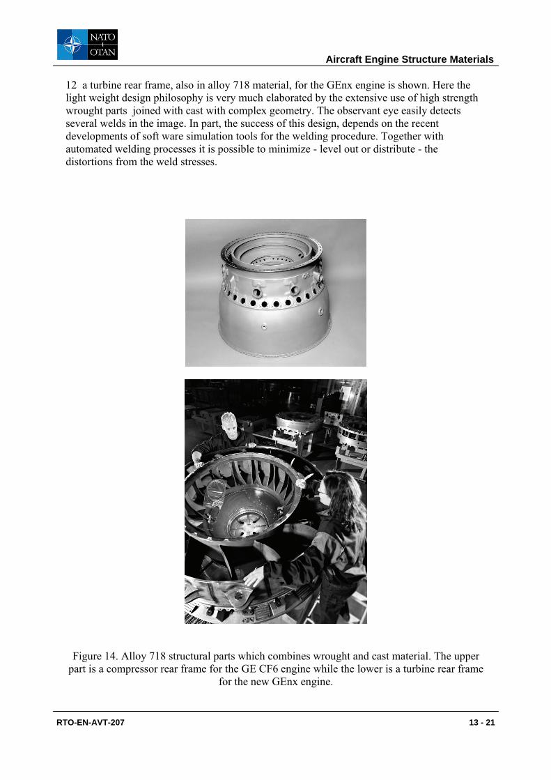
12 a turbine rear frame, also in alloy 718 material, for the GEnx engine is shown. Here the light weight design philosophy is very much elaborated by the extensive use of high strength wrought parts joined with cast with complex geometry. The observant eye easily detects several welds in the image. In part, the success of this design, depends on the recent developments of soft ware simulation tools for the welding procedure. Together with automated welding processes it is possible to minimize - level out or distribute - the distortions from the weld stresses.
Figure 14. Alloy 718 structural parts which combines wrought and cast material. The upper part is a compressor rear frame for the GE CF6 engine while the lower is a turbine rear frame
for the new GEnx engine.
Aircraft Engine Structure Materials
RTO-EN-AVT-207 13 - 21
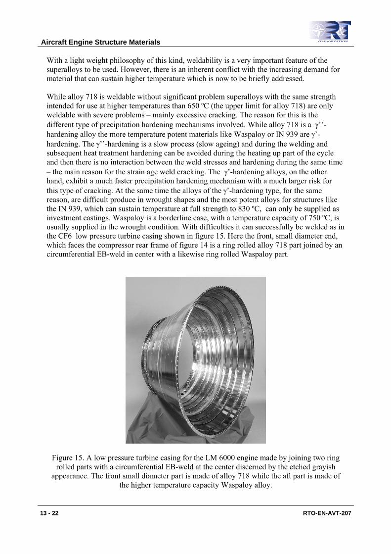
With a light weight philosophy of this kind, weldability is a very important feature of the superalloys to be used. However, there is an inherent conflict with the increasing demand for material that can sustain higher temperature which is now to be briefly addressed. While alloy 718 is weldable without significant problem superalloys with the same strength intended for use at higher temperatures than 650 ºC (the upper limit for alloy 718) are only weldable with severe problems – mainly excessive cracking. The reason for this is the different type of precipitation hardening mechanisms involved. While alloy 718 is a γ’’-hardening alloy the more temperature potent materials like Waspaloy or IN 939 are γ’-hardening. The γ’’-hardening is a slow process (slow ageing) and during the welding and subsequent heat treatment hardening can be avoided during the heating up part of the cycle and then there is no interaction between the weld stresses and hardening during the same time – the main reason for the strain age weld cracking. The γ’-hardening alloys, on the other hand, exhibit a much faster precipitation hardening mechanism with a much larger risk for this type of cracking. At the same time the alloys of the γ’-hardening type, for the same reason, are difficult produce in wrought shapes and the most potent alloys for structures like the IN 939, which can sustain temperature at full strength to 830 ºC, can only be supplied as investment castings. Waspaloy is a borderline case, with a temperature capacity of 750 ºC, is usually supplied in the wrought condition. With difficulties it can successfully be welded as in the CF6 low pressure turbine casing shown in figure 15. Here the front, small diameter end, which faces the compressor rear frame of figure 14 is a ring rolled alloy 718 part joined by an circumferential EB-weld in center with a likewise ring rolled Waspaloy part.
Figure 15. A low pressure turbine casing for the LM 6000 engine made by joining two ring rolled parts with a circumferential EB-weld at the center discerned by the etched grayish
appearance. The front small diameter part is made of alloy 718 while the aft part is made of the higher temperature capacity Waspaloy alloy.
Aircraft Engine Structure Materials
13 - 22 RTO-EN-AVT-207
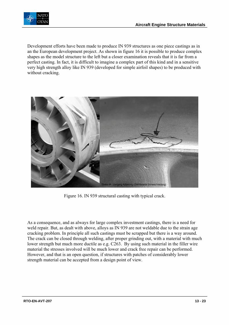
Development efforts have been made to produce IN 939 structures as one piece castings as in an the European development project. As shown in figure 16 it is possible to produce complex shapes as the model structure to the left but a closer examination reveals that it is far from a perfect casting. In fact, it is difficult to imagine a complex part of this kind and in a sensitive very high strength alloy like IN 939 (developed for simple airfoil shapes) to be produced with without cracking.
Figure 16. IN 939 structural casting with typical crack. As a consequence, and as always for large complex investment castings, there is a need for weld repair. But, as dealt with above, alloys as IN 939 are not weldable due to the strain age cracking problem. In principle all such castings must be scrapped but there is a way around. The crack can be closed through welding, after proper grinding out, with a material with much lower strength but much more ductile as e.g. C263. By using such material in the filler wire material the stresses involved will be much lower and crack free repair can be performed. However, and that is an open question, if structures with patches of considerably lower strength material can be accepted from a design point of view.
Aircraft Engine Structure Materials
RTO-EN-AVT-207 13 - 23

Aircraft Engine Structure Materials
13 - 24 RTO-EN-AVT-207