aircraft handling characteristics€¦ · advent of higher performance jet aircraft, and novel...
TRANSCRIPT

R. & M. No. 3566
M I N I S T R Y O F T E C H N O L O G Y
A E R O N A U T I C A L R E S E A R C H C O U N C I L
REPORTS A N D M E M O R A N D A
A Flight Simulator for Research into Handling Characteristics
By D. H. Perry, L. H. Warton and C. E. Welbourn
Aircraft
L O N D O N : H E R MAJESTY'S S T A T I O N E R Y O F F I C E
1969
PRICE £1 6s. 6d. NET

A Flight Simulator for Research into Handling Characteristics
By D. H. Perry, L. H. Warton and C. E. Welbourn
Aircraft
Reports and Memoranda No. 3566*
December, 1966
Summary .
The technical features of a piloted flight simulator, used in the study of aircraft handling qualities, are described. The equipment includes an analogue computer, several visual simulation systems using both direct optical and electronic techniques, and hydraulically driven motion systems for providing the pilot with acceleration cues.
Some comments on the effectiveness of these devices for simulating piloted flight are included.
Section.
1. Introduction
2. Historical Development
3. General Description of the Simulator
4. The Computer
4.1.
4.2.
4.3.
.
.
CONTENTS
Linear computation methods
Non-linear computation methods
Miscellaneous computer services
4.4. Comments on the computer capacity needed for handling qualities studies
Cockpit Instruments and Pilot's Flying Controls
5.1,
5.2.
5.3.
Visual
6.1.
6.2.
6.3.
6.4.
6.5.
Cockpit instruments
Pilot's flying controls
Engine noise simulation
Simulation
The 'Skyscape' projector
Runway shadowgraph display
VTOL shadowgraph
Contact analogue display
Closed circuit television equipment
*Replaces R.A.E. Technical Report 66 373--A.R.C. 29 324.

. . . . . . . . . . . . . . . . . . . . . . . . . . . . . . . . . . . . . . . . . . . . . . . . . . . . . . . . . . . . . . . . . . . . . . . . . . . . . . . . . . . . . . . . . . . . . . . . . . . . . . . . . . . . . . . . . . . . . . . . . . . . . . . . . . . . . . . . . . . . . . . . . . . . . . . . . . . . . . . . . . . . . . . . . . . . . . . . . . . . . . . . . . . . . . . i " i i . . . . . . . . . . . . . . . . . . . . .
CONTENTS- -con t inued
,
7.1.
7.2.
7.3.
7.4.
7.5.
Cockpit Motion
General description of the motion system - single seat cockpit
Motion system performance
Modifications to the motion system
Motion system for the transport aircraft cockpit
Fidelity of motion simulation
8. Recording Equipment
9. Concluding Remarks
Bibliography of Research Reports of Work Done on this Simulator
References
Appendices
Illustrations--Figs. 1 to 27
Detachable Abstract Cards
Appendix A
Appendix B
Appendix C
Appendix D
Appendix E
Appendix F
Appendix G
LIST OF APPENDICES
Technical details of equipment used in the analogue computer
Technical details of the random-noise generators
Technical details of the engine-noise generators
Technical details of the pitch, roll and azimuth servos used to drive the Skyscape pro- jector display
Technical details of the roll servomechanism used in the contact analogue display
Technical details of the closed circuit television visual simulation system
Technical details of the cockpit motion system
1. Introduction.
The purpose of this Report is to describe the technical features of a piloted flight simulator, which has been developed in the Aerodynamics Department, I~.A.E. Bedford, to aid the study of aircraft handling qualities.
The need for such equipment is twofold. Firstly, it enables the pilot to obtain practical experience of the characteristics of a proposed system at an early stage in the design, so that he may take a much more active part in its development. Secondly, by bringing the study of aircraft handling qualities into the laboratory, it enables systematic studies under controlled conditions to be conducted, with much greater ease, economy, and safety than can be achieved in real flight.
The development of flight simulation on its present scale has been made possible largely through advances in the fields of electronic computing and servo-control engineering. However, ground based

simulation can rarely, if ever, exactly reproduce the flight behaviour and environment sensed by the pilot in the real aircraft, and continuous efforts are being made to improve the techniques of simulation in order to minimise the effective differences. In this respect, much effort has been devoted on the present simulator to studying what needs to be represented in piloted simulation, particularly from the point of view of creating a lifelike flight environment. This involves consideration of such features as flight instrument displays, control feel characteristics, visual simulation of the outside world, and the re- presentation of the motion cues which occur in flight.
2. Historical Development. The development of the present flight simulator in Aerodynamics Department at Bedford may be
traced directly from the work done by Armament Department at R.A.E. Farnborough, firstly in develop- ing a gunnery training simulator 1'2, and then in building a research simulator, (A.F.S.I.M.), fdr studying aiming problems in fighter aircraft 2'a.
It is not surprising that the first experimental use of flight simulators for studying aircraft handling problems in the R.A.E. should Stem from this quarter, since, at that time, tracking during gunnery was one of the most precise tasks which a pilot was called upon to perform. This was therefore a flight condition inwhich any deficiencies in aircraft handling characteristics were likely to become most apparent. The advent of higher performance jet aircraft, and novel features such as S/VTOL, gave rise, however, to a whole range of handling problems in other flight regimes, and the need was increasingly felt for a more comprehensive simulator which could be used for studying these.
In 1956 A.F.S.I.M. was transferred to the Aerodynamics Department at Bedford to form the basis of this new research simulator. Experience showed that considerable modification was needed to suit it to its new role, and various interim arrangements, (as shown, for example, in Figs. 1 and 2), were used until 1960, when an extensive modernisation programme was carried out. This involved, amongst other things, the building of a new computer and the installation of a two degree of freedom cockpit motion system. The simulator remained substantially in this form, although with the continuous development of some items, until 1966, when larger scale developments, in the form of a transport aircraft type cockpit and an advanced visual simulation system, were added.
Meanwhile flight simulator development to cover other aspects of aircraft research and development has taken place in several R.A.E. Departments. The F.I.S.I.M. series of simulators 4'5'6'7'8 in I.E.E. Department have been used in the development of flight instruments and head up displays. Sparke and Calvert, in M.E. Department, have used a visual flight simulator 9 to study various arrangements of runway approach lighting patterns, and this work will also form part of the programme of a new simulator at the Blind Landing Experimental Unit, which is to be used for studying piloting problems arising during landings made under semi-automatic or fully automatic control.
The different research roles of these simulators have led to a varying emphasis on one or other aspect of simulation techniques. The main requirements in the case of the Aerodynamics Department simulator described here are for considerable flexibility with regard to the type of aircraft and flight regime which can be represented, together With an emphasis on reproducing, as closely as possible, the subtle physical cues which may be essential to a pilot in a difficult control task. Some other matters, such as the re- presentation of long range navigation equipment, or automatic control facilities, may be of less importance in this instance than with some of the other simulators mentioned above.
3. General Description of the Simulator. In the later sections of this Report the purpose and operation of the individual compbnents of the
simulator will be described in some detail. But first the overall arrangement of these components will be considered. Both functionally and physically the simulator may be divided into two parts; an electronic analogue computer, which determines the motion of the aircraft in response to disturbances or the pilot's control actions; and a cockpit position, closely resembling that of a real aircraft and provided with visual and other devices designed to represent the behaviour of the aircraft to the pilot as realistically as possible.

The general layout of the simulator laboratory is shown in Fig. 3 and an exterior view of the buildings is shown in Fig. 4. As will be seen from Fig. 3 two cockpit positions are available, one for representing single seat fighter or research type aircraft and the other for representing larger transport types. This larger cockpit has only recently been installed, and up till now the single seat cockpit has been used for simulating all types of aircraft. The layout of the individual cockpits is shown in more detail in Figs. 5 to 7. Both cockpits are mounted on motion systems, driven by hydraulic jacks, to provide some of the physical sensations of acceleration experienced by a pilot in flight. The pilots' positions are fitted with most of the controls and instruments normally provided in a real aircraft, and their layout can be modified, to some extent, to suit the particular type of aircraft which is under investigation.
• ~..,.~.
Each cockpit is housed in a dome shaped building, which forms a curved screen completely surrounthng the pilot. Images, representing the visual scene outside an aircraft, may be projected onto these screens by special optical equipment. Alternatively, the cockpit windscreen may be replaced by a large cathode ray tube, on which images of the outside world can be displayed.
The laboratory which houses the computer, with its control equipment and ancilliary services, is also shown in Figs. 5 and 6. The control desk is fitted with a duplicate set of the pilot's flight instruments, a monitor cathode ray tube, showing the view presented by the television visual simulation system, and equipment for measuring and recording the pilot's performance.
The computer and its services are considered in more detail in the following Section; cockpit instrumen~ and pilot's flying controls in Section 5; the cockpit motion systems in Section 6; the various methods of visual simulation in Section 7; and recording and other miscellaneous equipment in Section 8.
4. The Computer.
One of the main requirements for this simulator was that it should be capable of representing a wide variety of aircraft types, and that, in any given simulation, it should be possible to vary the values of individual parameters fairly readily. Such variations would be needed, for instance, in conducting a systematic study into the effect of different values of the aerodynamic derivatives on an aircraft's handling characteristics. This need for flexibility in the operation of the computer led to its arrangement as a general purpose machine, on which each problem is separately programmed as it arises. This arrangement also allows the computer to be used for the solution of any other problems where analogue methods are suitable, quite independently of the rest of the simulator.
The computer was built within R.A.E., and its design follows conventional methods 1° for non- transistorised d.c. analogue equipment, working on a reference voltage of q-i00 volts. The linear, non- linear, and other miscellaneous computer functions are described in the next three sub-sections. A general view of the computer is shown in Fig. 8.
4.1. Linear Computation Methods.
Linear computing operations, such as summation, integration and sign changing, are performed by d.c. operational amplifiers, consisting of high gain drift corrected amplifiers T M with appropriate resistive or capacitive feedback networks. There are 150 such operationalamplifiers in the linear part of the computer, each being assigned a specific computing operation, as shown in the Table :
Computing operation
Six input summers Two inputs with a gain of 1, two inputs with a gain of 3, and two inputs with a gain of 5.
Three input summers Two inputs with a gain of 1, one input with a gain of 2.
Number of amplifiers
40
32
4
L 4
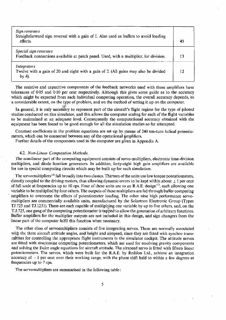
Sign reversers Straightforward sign reversal with a gain of 1. Also used as buffers to avoid loading
effects.
Special sign reversers Feedback connections available at patch panel. Used, with a multiplier, for division.
Integrators Twelve with a gain of 20 and eight with a gain of 2. (All gains may also be divided
by 4).
45
13
12
The resistive and capacitive components of the feedback networks used with these amplifiers have tolerances of 0"05 and 0.10 per cent respectively. Although this gives some guide as to the accuracy which might be expected from each individual computing operation, the overall accuracy depends, to a considerable extent, on the type of problem, and on the method of setting it up on the computer.
In general, it is only neceas~ry to represent part of the aircraft's flight regime for the type of piloted studies conducted on this simulator, and this allows .the computer scaling for each of the flight variables to be maintained at an adequate level. Consequently the computational accuracy obtained with the equipment has been found to be good enough for all the simulation studies so far attempted.
Constant coefficients in the problem equations are set up by means of 240 ten-turn helical potentio- meters, which can be connected between any of the operational ~mplifiers.
Further details of the components used in the computer are given in Appendix A.
4.2. Non-Linear Computation Methods. The non-linear part of the computing equipment consists of servo-multipliers, electronic time-division
multipliers, and diode function generators. In addition, forty-eight high gain amplifiers are available for use in special computing circuits which may be built up for each simulation.
The servomultipliersl° fall broadly into two classes. Thirteen of the units use low torque potentiometers, directly coupled to the driving motors, thus allowing dynamic errors to be kept within about ± 1 per cent of full scale at frequencies up to 10 cps. Four of these units are to an R.A.E. design 13, each allowing one variable to be multiplied by four others. The outputs of these multipliers are fed through buffer computing amplifiers to overcome the effects of potentiometer loading. The other nine high performance servo- multipliers are commercially available units, manufactured by the Solartron Electronic Group (Types TJ.725 and TJ.1231). These are each capable of multiplY, ing one variable by up to five others, and, on the T.J.725, one gang of the computing potentiometer is tapped'to allow the generation of arbitrary functions. Buffer amplifiers for the multiplier outputs are not included in this design, and sign changers from the linear part of the computer fulfil this function when necessary.
The other class of servomultipliers consists of five integrating servos. These are normally associated with. the three aircraft attitude angles, and height and airspeed, since they are fitted with synchro trans- tartars for controlling the appropriate flight instruments in the simulator cockpit. The attitude servos are fitted with sine/cosine computing potentiometers, which are used for resolving gravity components and solving the Euler angle equations for aircraft attitude. The airspeed servo is fitted with fifteen linear potentiometers. The servos, which were built for the R.A.E. by Redifon Ltd., achieve an integration accuracy of 5_ 1 per cent over their working range, with the phase shift held to within a few degrees at frequencies up to 7 cps.
The servomultipliers are summarised in the following table:
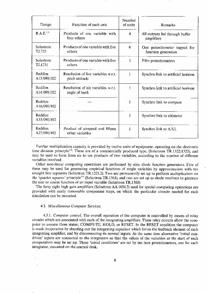
Number Design Function of each unit of units Remarks
R.A.E. 13 Products of one variable with 4 All outputs fed through buffer four others amplifiers
Solartron Products ofone variable with five 6 One potentiometer tapped for TJ.725 others function generation
Solartron Products of one variable with five 3 Film potentiometers TJ. 1231 others
1 Synchro link to artificial horizon Redifon A15/090/102
Redifon A14/090/102
Redifon A16/090/102
Redifon A33/090/102
Redifon A27/090/102
Resolution of five variables w.r.t. pitch attitude
Resolution of six variables w.r.t. angle of bank
Synchro link to artificial horizon
Synchro link to compass
Product of airspeed and fifteen other variables
Synchro link to altimeter
Synchro link to A.S.I.
Further multiplication capacity is provided by twelve units of equipment, operating on the electronic time division principle 1°. These are of a commercially produced type, (Solartron TR.1322/1323), and may be used to form from six to ten products of two variables, according to the number of different variables involved.
Other non-linear computing operations are performed by nine diode function generators. Five of these may be used for generating empirical functions of single variables by approximation with ten straight line segments (Solartron TR.1221.2). Two are permanently set up to perform multiplication on the 'quarter squares' principle 1° (Solartron TR.1361), and two are set up as diode resolvers to generate the sine or cosine function of an input variable (Solartron TR.1360).
The forty eight high gain amplifiers (Solartron AA. 1054.2) used for special computing operations are provided with easily removable component trays, on which the particular circuits needed for each simulation can be mounted.
4.3. Miscellaneous Computer Services.
4.3.1. Computer control. The overall operation of the computer is controlled by means of relay circuits which are associated with each of the integrating amplifiers. These relay circuits allow the com- puter to assume three states; COMPUTE, HOLD, or RESET. In the RESET condition the computer is made inoperative by shunting out the integrating capacitor which forms the feedback element of each integrating amplifier, and by disconnecting its normal inputs. At the same time alternative 'initial con- dition' inputs are connected to the integrators so that the values of the variables at the start of each computation may be set up. These 'initial conditions' are set by ten turn potentiometers, one for each integrator, mounted on the control desk.

In the COMPUTE condition the shunts across the integrating capacitors are removed and the normal inputs reconnected, so that the integrating amplifier functions in the normal way. Finally, in the HOLD condition the integrating capacitor is isolated, in such a way that it retains the voltage which charged it at the instant of switching from COMPUTE to HOLD. This facility allows the whole computation to be 'frozen' if an incident of particular interest should arise, so that it can be examined in some detail. Subsequently the computation may be continued from this condition by switching back from HOLD to COMPUTE.
It is important that the relay switching operations which control the condition of the computer should occur virtually simultaneously for all the integrators involved in a given computation. On the other hand, occasions may arise when part of the computation commences only after some time, or upon some significant event in an existing computation. This might occur, for instance, in the simulation of an aircraft taking off, when part of the computation would only start with the simulated aircraft becoming airborne. To meet this need, each of the twenty integrating amplifiers may be assigned to either of two control channels, both being provided with COMPUTE, HOLD and RESET facilities.
Should the excursions of the variables during a simulation carry the computation outside the normal working range (i.e. roughly ± 100 volts), a warning is given by an overload system. This overload system may be arranged so that the warning continues until it is manually cancelled, or so that it cancels auto- matically when the computation returns inside the working range. Alternatively the system may be made to switch the whole computation to the HOLD condition whenever an overload occurs.
4.3.2. Programme set-up. The individual computing amplifiers, potentiometers, multipliers, etc. are connected together to form the overall computation network by means of a central patching panel, having over 2300 terminations. Inputs and outputs of all units appear on this panel, some of the outputs being repeated several times. Leads carrying signals from the pilot's controls, together with the output leads to flight instruments, cockpit motion system and visual simulation equipment, are also terminated at this panel. Interconnections are made by screened patchcords, and for a typical flight simulation study these may number six hundred or more. The patchcords are set up on removable phag-in patch- boards, so that once a programme has been arranged it can be detached from the computer, stored, and brought back into use as often as is needed.
The other major item in programming the computation involves setting the numerical values of the equation coefficients onto the computing potentiometer. This is achieved by the use of special jacking points, which enable a standard voltage, (usually 100 volts), to be applied to the potentiometer input, with the normal input being temporarily disconnected. The output of the amplifier connected to the potentiometer can then be monitored, while the potentiometer is adjusted to give the desired coefficient setting. This direct method of setting the potentiometer automatically allows for any slight inaccuracies in the nominal gain of the computing amplifier, and for the effects of potentiometer loading.
4.3.3. Computer monitoring. The functioning of the computer may be monitored from the central control desk, which contains switching and warning lamps for all power supplies, indication of computer overload, sensitive meters showing the voltage level of the reference power supplies and a ripple monitor for inspecting the noise level of the amplifier outputs.
The output of any computing amplifier may be displayed, via a switch selected panel, on a digital voltmeter, on one of six pointer type voltmeters, or on a twin trace oscilloscope. In addition, these outputs may be permanently recorded on the continuous trace recorders described in Section 8.
4.3.4. Random noise generation for gust representation. The effects of atmospheric turbulence form the principal disturbing factor acting on an aircraft in trimmed flight, and their representation is an essential feature of many simulator handling studies. The technique employed on this simulator is to feed random signals into the computer at the appropriate stages, so as to represent the fluctuations in airspeed, incidence and sideslip caused by the gusts.
The random signals are produced by a form of electronic noise generator designed by Douce and Shackleton 14, which is capable of providing a substantially uniform power spectrum from very low frequencies up to about 15 cps. This uniform spectrum may then be shaped by filters to produce a spectrum

which is typical of that measured for atmospheric turbulence. Further details of this method of gust generation are given in Appendix B, and the theoretical and measured spectra are compared in Fig. B.2.
Three separate noise generators are used to provide uncorrelated outputs, which represent the longi- tudinal, lateral and vertical components of atmospheric turbulence.
In addition to gust representation these noise generators may be used in other situations where a randomly fluctuating signal is required, for instance in representing runway roughness during the ground run.
4.4. Comments on the Computer Capacity Needed for Handling Qualities Studies. In general, the difficulties of providing the pilot with adequate flying cues have proved more of a
limitation in the simulation studies made so far, than have considerations of computer capacity, or accuracy. There has, however, been a continuing need to increase the computer capacity as the scope of the simulations attempted has enlarged, and the number of computing amplifiers and non-linear units employed has roughly doubled during the last three years. As a rough guide to computing equipment requirements, the number of amplifiers, etc. needed in several simulations of varying complexity, are listed below.
(i) Conventional aircraft - limited equations and 9uidance. Small perturbation equations of motion with constant aerodynamic derivatives. Simple guidance for instrument approaches. Turbulence re- presented. 80 amplifiers. 85 coefficient setting potentiometers. 330 patching connections.
(ii) VTOL aircraft. Small perturbation equations for jet-borne hovering. Non-linear kinematic terms, but very simple aerodynamics. Ground position computed for external world visual display. 80 amplifiers. 75 coefficient setting potentiometers. 280 patching connections. 6 non-linear units.
(iii) Conventional aircraft - fu l l equations, no guidance. Full equations of motion with wide range of speed variation. Very complete representation of kinematics. Some non-linear aerodynamics. No guidance or ground position. Turbulence represented. 115 amplifiers. 130 coefficient setting potentio- meters. 500 patching connections. 13 non-linear units.
(iv) Conventional aircraft - fu l l equations and guidance. Full equations of motion with wide range of speed variation. Complete representation of kinematics and non-linear aerodynamics, including ground effect. Ground restraint due to undercarriage during take-off and landing. Ground position computed for external world visual display. Turbulence and crosswinds. Take-off director, and guidance for instru- ment approaches. 160 amplifiers. 230 coefficient setting potentiometers. 800 patching connections. 55 non-linear units and special amplifiers.
5. Cockpit Instruments and Pilot's Flying Controls.
5.1. Cockpit Instruments. Earlier experience with the rudimentary type of simulator illustrated in Figs. 1 and 2 had shown that
it was very desirable to make the presentation and mode of operation of the simulated flight instruments resemble, as closely as possible, those of the real aircraft instruments, which pilots were using everyday in flight. For instance, in the case of the vertical speed indicator, it was evident that the pilot gained information almost as readily from the general geometry of the pointer's position, as from consciously reading the pointer indication against the scale. This depended, however, on his familiarity with the instrument; consequently an unusual set of instruments in the simulator caused additional difficulties for the pilot.
The frequent use of multi-turn dial displays in flight instrument practice presents difficulties in using the simpler type of electrical meter movements for fligh t instrument simulation, and it is often necessary to produce special adaptations of the flight instruments, using synchro or servo drives. This difficulty is becoming less acute with the adoption of remote reading instruments in aircraft, as these are usually readily adaptable to flight simulator use.
The instrument panel layout used in the single seat cockpit may be seen in the various views, Figs. 9 to 11, which also show how the arrangement of the individual instruments may be changed for different simulation studies.
The method of driving each of the instruments is outlined below:
Artificial horizon - Mk.4 (Figs. 9,10). Servo operated in both pitch and roll with 400 c/s two ighase servomotors and control transformer
synchros, slaved to synchro control transmitters on the pitch and roll computing servos (Section 4.2).
Artificial horizon - F4B. Dh'ector horizon (Fig. 11).
This is a standard aircraft instrument which is normally driven from a master reference gyro through a synchro link. For simulator use the synchro transmitters are driven by small d.c. position servos in response to computer pitch and roll signals.
Compass - Gyro unit Mk.4B.
This is a standard aircraft instrument .which is slaved to a synchro control transmitter on the yaw computing servo (Section 4.2).
Airspeed indicator Mk.9M.
Operated by a torque synchro slaved to a synchro transmitter on the airspeed computing servo (Section 4.2).
Altimeter Mk. 19. Operated by atorque synchro slaved to a synchro transmitter on the altitude computing servo (Section
4.2). The simulated rate of climb indicator Mk. 3, turn and slip indicator Mk.2A, and Machmeter Mk.3B
are driven by moving coil, meter type movements. 5.2. Pilot's Flying Controls.
Poor mechanical characteristics of the pilot's flying controls are frequently as much to blame for unsatisfactory handling behaviour as are the aircraft's dynamic properties. It is therefore important that the feel of the aircraft's controls should be accurately represented on the simulator. Fortunately, the advent of irreversible powered flying controls, coupled with artificial feel systems, in real aircraft has considerably eased the task of representing control forces on the simulator, since the often complex variation in aerodynamic hinge moments do not now directly affect the piloting of the aircraft. In its usual form the control layout used in the single seat cockpit consists of a central, fighter type control column, conventional rudder pedals and a throttle mounted on the port console (Fig. 10). An alternative arrangement allows the representation of a control wheel (Fig. 11) in place of the control stick, where a layout typical of larger aircraft is required. In the transport aircraft cockpit, conventional dual controls are fitted (Fig. 12).
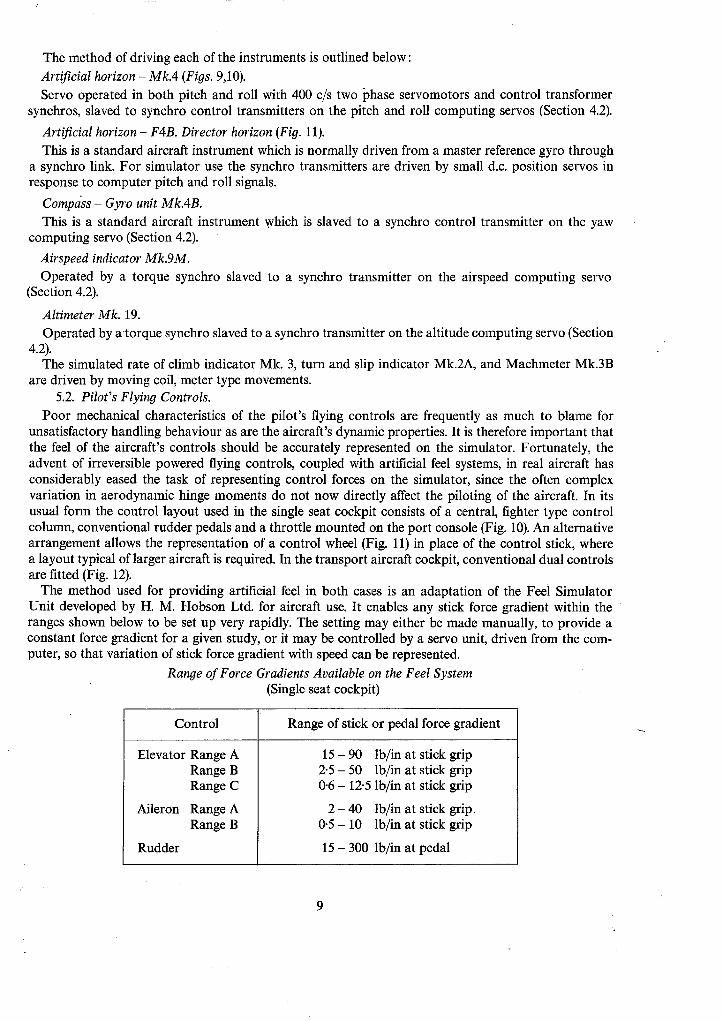
The method used for providing artificial feel in both cases is an adaptation of the Feel Simulator Unit developed by H. M. Hobson Ltd. for aircraft use. It enables any stick force gradient within the ranges shown below to be set up very rapidly. The setting may either be made manually, to provide a constant force gradient for a given study, or it may be controlled by a servo unit, driven from the com- puter, so that variation of stick force gradient with speed can be represented.
Range of Force Gradients Available on the Feel System (Single seat cockpit)
Control Range of stick or pedal force gradient
Elevator Range A
Aileron
Rudder
Range B Range C
Range A Range B
15 - 90 lb/in at stick grip 2.5 - 50 lb/in at stick grip 0-6 - 12-5 lb/in at stick grip
2 - 40 lb/in at stick grip 0.5 - 10 lb/in at stick grip
15 - 300 lb/in at pedal

Provision is also made for adjusting the break out force on the elevator, aileron and rudder controls within the range 0 - 10 lb. Trimming is available on the elevator control only for the single seat cockpit, but about all three axes for the transport aircraft cockpit. The operation of the feel system, taking the elevator as an example, is described in detail below.
5.2.1. Operation of the elevator control. The operating principles of the feel and trimming system are shown diagrammatically in Fig. 13. The control stick is connected to a pivoted feel jack through a simple knuckle joint. The pressure in the jack, for a given setting of stick force gradient, is held constant by a special hydraulic regulator, irrespective of movements of the jack piston. Fig. 13a and b show how, when the control stick is displaced, the line of action of the jack force no longer passes through the stick pivot, but provides a restoring moment which is proportional to the stick displacement over the small range of movement that is involved. Fig. 13c shows how this restoring moment can be eliminated by rotating the trimming arm, which carries the feel jack, until the line of action of the jack force once more passes through the stick pivot. Movement of the trimming arm is effected by an electrical actuator which is controlled by the pilot's trim button on the top of the stick.
As mentioned earlier, the mechanical properties of this feel system are of very great importance, the more so, because the signal potentiometer, which feeds control movements to the computer, is directly coupled to the stick and therefore subject to the minimum of mechanical backlash. Imperfections in the feel system may give rise to a situation in which the pilot can make a small control movement, which affects the aircraft's simulated flight, but gives rise to no change in control force. This particular control deficiency has been found more difficult to contend with than a straightforward backlash or dead zone affecting both aircraft response and stick force.
Difficulties of the type just mentioned were initially experienced with the present feel system, due to less than perfect engineering. In particular great care had to be taken in eliminating such features as backlash at the trim actuator, flexibility of the trimming arm, and small amounts of play in bearings, universal joints, etc. before a satisfactory system was achieved.
5.3. Engine Noise Simulation. With any simulation equipment which contains a large number of electromechanical devices it is
difficult to avoid extraneous noises from relays, servos, etc., which tend to distract the pilot and destroy the illusion of a flight environment. Simulated engine noise may be used to conceal the more obtrusive noises, while at the same time adding to the realism of the simulation. Noises made by the nose and main wheels during take-off have also been found to provide the pilot with valuable cues as to the progress of the manoeuvre. Further details of the engine noise generator are given in Appendix C, and of the random noise generator used for wheel rumble in Appendix B.
6. Visual Simulation. In addition to the flight instrument display described in Section 5.1, various methods are available
for providing the pilot with a visual simulation of his view outside the aircraft. In the following Sections five methods are described in detail:
The 'Skyscape' projector
Runway shadowgraph
VTOL shadowgraph
Contact analogue
Closed circuit T.V.
The first of these depend on direct projection techniques using a 'point-source' of light. The latter two depend basically on electronics in one form or another.
10
6.1. The 'Skyscape' Projector. This method of simulating the view from an aircraft was first developed for use with the R.A.E. Fixed
Gun Fighter Trainer 1. It relies on direct projection of a cloudy sky scene and horizon, painted on the surface of a transparent sphere and illuminated by a point source of light at its centre. The projected picture is cast onto a curved screen surrounding the pilot. In order to represent aircraft attitude changes the projector is mounted on a servo-driven gimbal system, so that the sky scene can be rotated in pitch, roll and yaw relative to the pilot. The projector itself is shown in Fig. 14, and a general inapression of the visual scene may be gained from Fig. 15.
The light source used is a 36 watt filament lamp. The factors limiting the power of this lamp are partly those of heat dissipation, and, perhaps more important, the brightness level at which joints and im- perfections in the screen surface become apparent, thus destroying the illusion of motion given to the observer by movement of the sky scene. The 30 foot diameter screen is built up of many hardboard sections, and the most frequent cause of difficulty has been cracking between these sections, due largely, it is thought, to changes in temperature and humidity.
The screen shape is hermispherical in the upper half and simi-elliptical in the lower half. From the visual projection point of view a completely spherical screen would have been more suitable, but this was less practical because of the greater height that the pilot would need to sit above the ground. With the simple type of projected displays used so far, distortion due to the screen shape has not been apparent.
Small d.c. servomotors, acting as position controls, drive the projector in pitch and roll. Full technical details are given in Appendix D. Frequency response measurements of these servo systems are shown in Figs. D.1, D.2, D.3. Initially the roll performance was considered to be inadequate, there being a delay which was detectable to the pilot before any indication of rolling motion occurred. This deficiency was eliminated by the increased gain which could be used, following the fitting of a tachogenerator to provide velocity feedback to the servo.
The projector drive in yaw is provided by a 400 c/s two phase servomotor, acting as a position control, slaved to a synchro transmitter on the yaw computing servo (Section 4.2).
One great advantage of this form of visual simulation is the almost unlimited field of view which can be provided. Attitude information is therefore available to the pilot through his peripheral vision, even when he is not looking directly at the visual scene, and most pilots find its representation of angular motion very compelling. Many pilots confess to a feeling of nausea, ranging in different pilots from slight to very severe. The effect is particularly apparent when the visual simulation is used without cockpit motion, but it seems to be markedly less troublesome to non-pilot subjects. A possible explanation, in terms of a conflict between the compelling visual sensations of motion, unaccompanied by the other expected physical sensations, has been advanced by Whiteside 15. Other features which have been suggested as adding to the effect are the rather diffuse nature of the horizon and clouds, which are similar to conditions in which slight disorientation, and a corresponding feeling of nausea, are sometimes experienced in the air. Another possible factor is that the pilot was sitting slightly below the horizon level, giving a sensation which has been described as 'like sitting in a bowl'. This feature can, however, be eliminated by suitable positioning of the projection filament.
6.2. Runway Shadowgraph Display. While the Skyscrape projector described above has proved to be a very effective method of simulating
visual flight at altitude, it provides no reference to the aircraft's position over the ground, and is therefore unsuitable for studies into take-off and landing. In an attempt to overcome this deficiency, a modification was devised which aimed at representing the principal perspective features of a runway, as seen by the pilot during take-off or landing. This equipment retained the gimbal system and servo drives of the original Skyscape projector, but the spherical cloudscape transparency was removed and the runway projector substituted. This runway projector (Fig. 16) consisted of a triangular semi-transparent plate, having scribed on it a number of lines radiating from the apex. The point light source in this case was a 2 watt lamp having an exceptionally small filament. An example of the projected picture is given in Fig. 17.
11
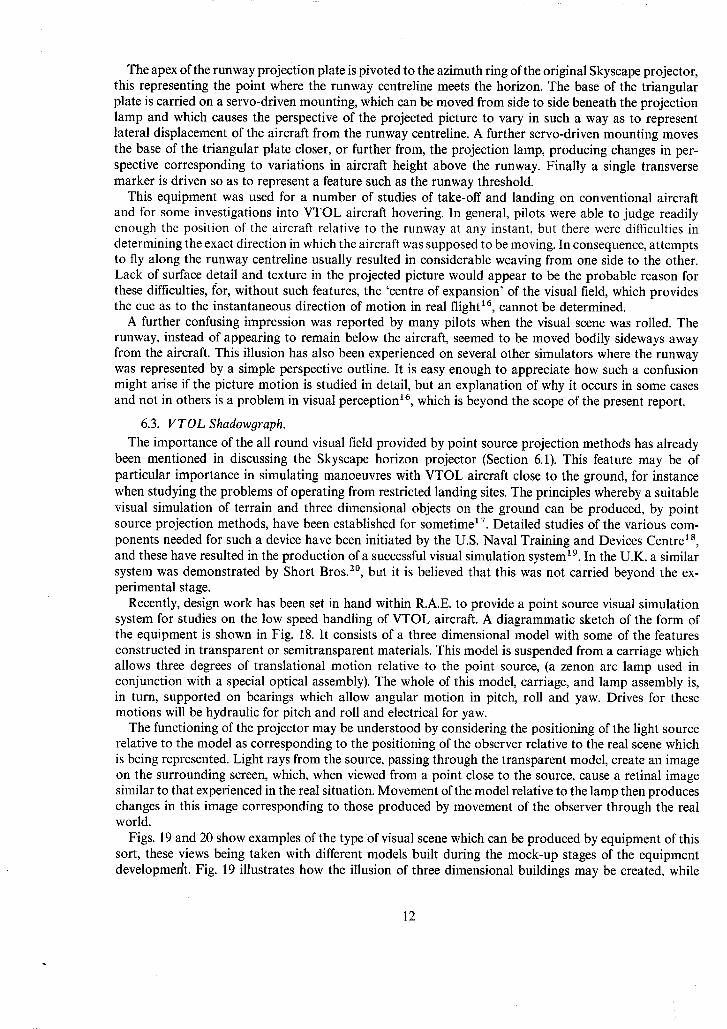
The apex of the runway projection plate is pivoted to the azimuth ring of the original Skyscape projector, this representing the point where the runway centreline meets the horizon. The base of the triangular plate is carried on a servo-driven mounting, which can be moved from side to side beneath the projection lamp and which causes the perspective of the projected picture to vary in such a way as to represent lateral displacement of the aircraft from the runway centreline. A further servo-driven mounting moves the base of the triangular plate closer, or further from, the projection lamp, producing changes in per- spective corresponding to variations in aircraft height above the runway. Finally a single transverse marker is driven so as to represent a feature such as the runway threshold.
This equipment was used for a number of studies of take-off and landing on conventional aircraft and for some investigations into VTOL aircraft hovering. In general, pilots were able to judge readily enough the position of the aircraft relative to the runway at any instant, but there were difficulties in determining the exact direction in which the aircraft was supposed to be moving. In consequence, attempts to fly along the runway centreline usually resulted in considerable weaving from one side to the other. Lack of surface detail and texture in the projected picture would appear to be the probable reason for these difficulties, t'or, without such features, the 'centre of expansion' of the visual field, which provides the cue as to the instantaneous direction of motion in real flight 16, cannot be determined.
A further confusing impression was reported by many pilots when the visual scene was rolled. The runway, instead of appearing to remain below the aircraft, seemed to be moved bodily sideways away from the aircraft. This illusion has also been experienced on several other simulators where the runway was represented by a simple perspective outline. It is easy enough to appreciate how such a confusion might arise if the picture motion is studied in detail, but an explanation of why it occurs in some cases and not in others is a problem in visual perception 16, which is beyond the scope of the present report.
6.3. VTOL Shadowgraph. The importance of the all round visual field provided by point source projection methods has already
been mentioned in discussing the Skyscape horizon projector (Section 6.1). This feature may be of particular importance in simulating manoeuvres with VTOL aircraft close to the ground, for instance when studying the problems of operating from restricted landing sites. The principles whereby a suitable visual simulation of terrain and three dimensional objects on the ground can be produced, by point source projection methods, have been established for sometime 17. Detailed studies of the various com- ponents needed for such a device have been initiated by the U.S. Naval Training and Devices Centre is, and these have resulted in the production of a successful visual simulation system ~ 9. In the U.K. a similar system was demonstrated by Short Bros. 2°, but it is believed that this was not carried beyond the ex- perimental stage.
Recently, design work has been set in hand within R.A.E. to provide a point source visual simulation system for studies on the low speed handling of VTOL aircraft. A diagrammatic sketch of the form of the equipment is shown in Fig. 18. It consists of a three dimensional model with some of the features constructed in transparent or semitransparent materials. This model is suspended from a carriage which allows three degrees of translational motion relative to the point source, (a zenon arc lamp used in conjunction with a special optical assembly). The whole of this model, carriage, and lamp assembly is, in turn, supported on bearings which allow angular motion in pitch, roll and yaw. Drives for these motions will be hydraulic for pitch and roll and electrical for yaw.
The functioning of the projector may be understood by considering the positioning of the light source relative to the model as corresponding to the positioning of the observer relative to the real scene which is being represented. Light rays from the source, passing through the transparent model, create an image on the surrounding screen, which, when viewed from a point close to the source, cause a retinal image similar to that experienced in the real situation. Movement of the model relative to the lamp then produces changes in this image corresponding to those produced by movement of the observer through the real world.
Figs. 19 and 20 show examples of the type of visual scene which can be produced by equipment of this sort, these views being taken with different models built during the mock-up stages of the equipment developmedt. Fig. 19 illustrates how the illusion of three dimensional buildings may be created, while
12
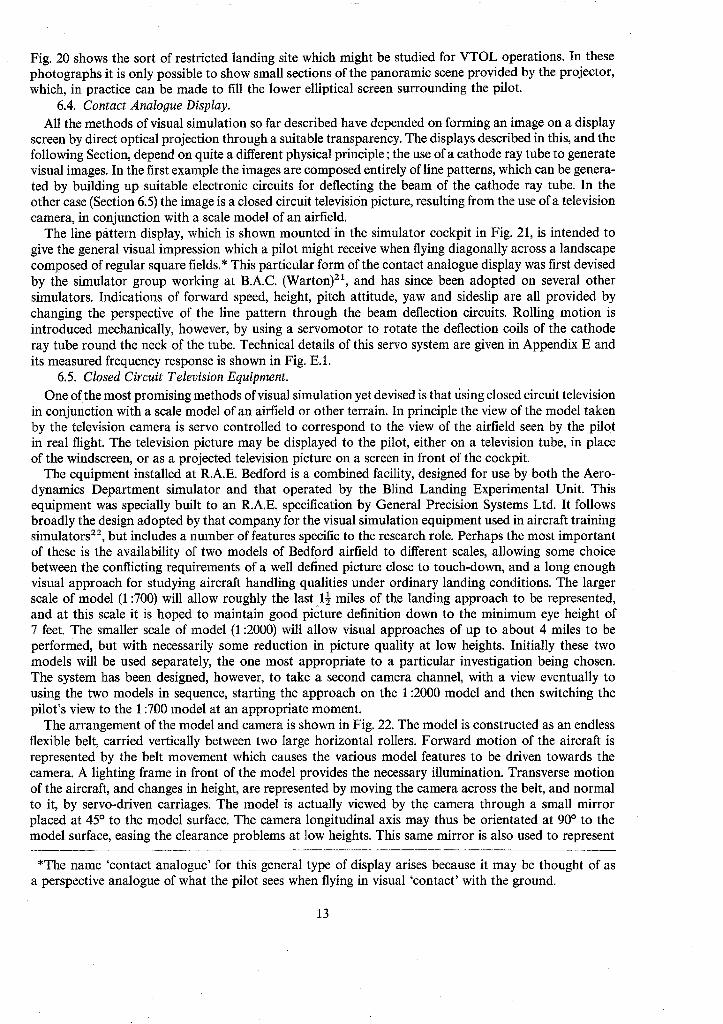
Fig. 20 shows the sort of restricted landing site which might be studied for VTOL operations. In these photographs it is only possible to show small sections of the panoramic scene provided by the projector, which, in practice can be made to fill the lower elliptical screen surrounding the pilot.
6.4. Contact Analogue Display. All the methods of visual simulation so far described have depended on forming an image on a display
screen by direct optical projection through a suitable transparency. The displays described in this, and the following Section, depend on quite a different physical principle; the use of a cathode ray tube to generate visual images. In the first example the images are composed entirely of line patterns, which can be genera- ted by building up suitable electronic circuits for deflecting the beam of the cathode ray tube. In the other case (Section 6.5) the image is a closed circuit television picture, resulting from the use of a television camera, in conjunction with a scale model of an airfield.
The line p~ittern display, which is shown mounted in the simulator cockpit in Fig. 21, is intended to give the general visual impression which a pilot might receive when flying diagonally across a landscape composed of regular square fields.* This particular form of the contact analogue display was first devised by the simulator group working at B.A.C. (Warton) zl, and has since been adopted on several other simulators. Indications of forward speed, height, pitch attitude, yaw and sideslip are all provided by changing the perspective of the line pattern through the beam deflection circuits. Rolling motion is introduced mechanically, however, by using a servomotor to rotate the deflection coils of the cathode ray tube round the neck of the tube. Technical details of this servo system are given in Appendix E and its measured frequency response is shown in Fig. E. 1.
6.5. Closed Circuit Television Equipment. One of the most promising methods of visual simulation yet devised is that rising closed circuit television
in conjunction with a scale model of an airfield or other terrain. In principle the view of the model taken by the television camera is servo controlled to correspond to the view of the airfield seen by the pilot in real flight. The television picture may be displayed to the pilot, either on a television tube, in place of the windscreen, or as a projected television picture on a screen in front of the cockpit.
The equipment installed at R.A.E. Bedford is a combined facility, designed for use by both the Aero- dynamics Department simulator and that operated by the Blind Landing Experimental Unit. This equipment was specially built to an R.A.E. specification by General Precision Systems Ltd. It follows broadly the design adopted by that company for the visual simulation equipment used in aircraft training simulators 22, but includes a number of features specific to the research role. Perhaps the most important of these is the availability of two models of Bedford airfield to different scales, allowing some choice between the conflicting requirements of a well defined picture close to touch-down, and a long enough visual approach for studying aircraft handling qualities under ordinary landing conditions. The larger scale of model (1:700) will allow roughly the last 1½ miles of the landing approach to be represented, and at this scale it is hoped to maintain good picture definition down to the minimum eye height of 7 feet. The smaller scale of model (1:2000) will allow visual approaches of up to about 4 miles to be performed, but with necessarily some reduction in picture quality at low heights. Initially these two models will be used separately, the one most appropriate to a particular investigation being chosen. The system has been designed, however, to take a second camera channel, with a view eventually to using the two models in sequence, starting the approach on the 1:2000 model and then switching the pilot's view to the 1:700 model at an appropriate moment.
The arrangement of the model and camera is shown in Fig. 22. The model is constructed as an endless flexible belt, carried vertically between two large horizontal rollers. Forward motion of the aircraft is represented by the belt movement which causes the various model features to be driven towards the camera. A lighting frame in front of the model provides the necessary illumination. Transverse motion of the aircraft, and changes in height, are represented by moving the camera across the belt, and normal to it, by servo-driven carriages. The model is actually viewed by the camera through a small mirror placed at 45 ° to the model surface. The camera longitudinal axis may thus be orientated at 90 ° to the model surface, easing the clearance problems at low heights. This same mirror is also used to represent
*The name 'contact analogue' for this general type of display arises because it may be thought of as a perspective analogue of what the pilot sees when flying in visual 'contact' with the ground.
13

pitch attitude changes of the aircraft, since small changes in its inclination to the model surface produce apparent changes in the position of the horizon, and thus give the effect of pitch attitude changes. Simi- larly the aircraft's rolling and yawing motions are represented by the rotation of small optical com- ponents in front of the camera which cause appropriate changes in the appearance of the televised picture.
Various views, typical of those which may be presented to the pilot, are shown in Figs. 23 and 24. The specification and performance measurements for the equipment are given in Appendix F.
7. Cockpit Motion.
The need for some form of visual simulation is self evident if the representation of certain flying tasks, for instance landing, is to be attempted at all. The need for motion simulation on the other hand is not so immediately evident, and because it has been technically amongst the most difficult of the flying cues to represent accurately, there has been much discussion about the need for representing it at all. One of the arguments sometimes used to decry the need for motion simulation is that pilots are deliberately trained to ignore motion sensations in flight because it is known that they can sometimes be misleading. It is felt, however,, that such an argument is based on an over-generalization. Our work on simulation with and without the motion cue 8 indicates that it does play an important part in the control of the aircraft, and there now seems little doubt that the pilot's sensing of angular and translational accelerations is not, in fact. ignored in flight. The confusion arises because the pilot is a poor integrator of these ac- celerations, and consequently his judgment of velocities, positions and attitudes, based only on motion sensations, is likely to be sadly astray 23.
7.1. General Description of the Motion System - single seat cockpit.
The motion system used with this simulator has angular freedoms in pitch and roll only (Fig. 25), but the pilot is seated some six feet ahead of the pitching axis so that heaving motion enhances the angular rotation cue. When the pitch motion is in the neutral position the rolling axis coincides roughly with the pilot's chest (Fig. 26), but as this axis remains fixed in space, the pilot may be sitting either above or below the rolling axis according to whether the cockpit is pitched up or down. This feature has not given rise to any pilot comment. The working range of movement in pitch is from 10 ° nose down to 20 ° nose up, giving a total vertical movement of 3 feet at the cockpit. The range of movement in roll is 15 deg either side of the vertical.
The mechanism is driven by hydraulic jacks operating at a system pressure of 3000 psi. These form part of positional servo systems, using linear potentiometers and velocity transducers as the feedback elements which, combined with the input signals from the computer, drive the jack spool valves by means of electrical torque motors. The out of balance moment due to the overhanging cockpit is reacted by a separate, constant-force, ram, so that the driving jacks have only to overcome the inertial load of the cockpit.
Protection against runaways and excessive signal inputs is provided, firstly by electrical limiting of the input signal, and then by microswitch operated relays, which cause the driving current to the jack valve to be reversed as the movement limits are approached. Finally, in the event of a severe runaway, hydraulic cushioning is provided at each end of the jack travel.
The control gear includes an electrically operated shut off valve which prevents hydraulic pressure frona being applied to the mechanism before the electrical circuits have been energised. Also, means for progressively attentuating any input signals when the locks are being engaged or removed is provided.
7.2. Motion System Performance.
The specification for the moti,n system performance is reproduced in Appendix G, together with measurements of the performance actually achieved. It will be seen that the required performance in terms of steady rates and accelerations was generally reached, but that the dynamic performance as indicated by the frequency response curves Figs. G.1, G.2 was poorer than that specified. It is believed 24 that this stems largely from the rather low natural frequency of the system - about 4 cps. In the event the minimum phase lag which could be achieved, (measured at 1 cps) was about 30 deg, but the gain
14

setting needed to achieve this caused the motion quality to be rather harsh and noisy. Lowering the gain setting produced a motion of smoother quality but this was attended, of course, by larger phase lags.
Apart from the overall difficulty of achieving a motion quality resembling that of an aircraft in flight, a particular problem with this, as with other motion systems, has been in achieving a smooth reversal in the direction of motion; that is to say in avoiding a sudden jerk as the motion starts. Analogue com- puter studies have suggested several possible causes, such as jack friction and valve lap, apart from the obvious ones like mechanical backlash. Some improvement has already been achieved by relocating the feedback elements closer to the jacks themselves, while further modifications to incorporate low friction hydraulic seals are planned.
7.3. Modifications to the Motion System. Two modifications to this motion system to increase the number of degrees of freedom have been
considered. The first is to replace the fixed strut, which at present determines the attitude setting of the cockpit on the end of the beam, by a hydraulic ram type of position servo. This would allow an independent pitching motion of the cockpit alone, and, when combined with the existing motion of the beam, could be used to provide freedom in heave. So far no detailed work has been done on this development.
The second modification, which is at present in the design stage, is to provide yaw motion by mounting the whole of the existing equipment on a turntable. It is planned to use a naval gun turret mounting as the bearing, and to allow a freedom in yaw of + 15 deg.
7.4. Motion System for the Transport Aircraft Cockpit. This cockpit is mounted on a three degree of freedom motion system, manufactured by Redifon Ltd.,
and of a type 2s usually used with aircrew training simulators (Fig. 27). The range of movement in pitch is from 10 ° nose down to 15 ° nose up, in roll, ± 10 °, and in heave, + 12 inches. The velocity and accelera- tion performance in roll has been increased, for the research r61e, by doubling the number of control valves fitted to the hydraulic jacks, and by fitting an extra roll jack. The weight of the cockpit carried on the motion system is about 4000 lb, but the moving mechanism has been tested with loads of up to 9000 lb.
7.5. Fidelity of Motion Simulation. With the limited ranges of movement available with these mechanisms it is obviously not possible to
reproduce exactly the accelerations experienced by the pilot in flight. In particular, sustained normal accelerations cannot be applied, and a false, sideslipping sensation is experienced when the cockpit is banked to represent steady turning flight. The solutions to these problems cannot be dealt with in detail here, since they vary from one type of study to another, but one or two general comments can be made.
Where the flying task consists predominantly of straight, rather than turning flight, as for instance in take-off or landing, it has been found acceptable to make the motion system attitude equal to that of the aircraft. The sideslipping sensation mentioned above is then present when the simulator is rolled, but its effect may not be too obtrusive if the bank angles are small. Where continuous banked manoeuvres are involved it is usual to reduce the spurious sideslipping sensation by allowing the cockpit attitude to return slowly to the horizontal position, while the flight instruments and visual simulation system continue to display the correct aircraft attitude. Smoothness of the operation of cockpit mechanism is particularly important with this technique.
8. Recording Equipment. The principal method of obtaining quantitative results from the handling tests made on the simulator
is by the analysis of continuous trace recordings of various flight parameters, taken while the pilot is performing simulated flying tasks. These parameters (for instance~ airspeed or aircraft attitude) are normally represented by the voltage outputs of various amplifiers in the computer. The recording equip- ment consists of two Brush Mark 200, eight channel pen recorders. Pen recorders were chosen, in prefer- ence to ultra violet or other types of photographic recorder, because it is frequently helpful in handling studies to be able to observe the record at the instant it is being made. Other features considered to be essential in the recorder were rectilinear writing across the paper, and servo-driven pens for accuracy and frequency response.
15

In some simulation tests there is a need to measure pilots' performance by, for instance, evaluating the mean error during a tracking task. This can be done by means of six low inertia integrating motors, driving resettable pointers, enabling the error 'scores' to be read off directly at the end of each run.
Landline links between the simulator laboratory and the Aero Flight Division data processing labora- tory enable the comprehensive tape recording and analogue-to-digital conversion equipment of the latter facility to be used, either for 'on-line' recording or for subsequent data reduction.
9. Concluding Remarks. Experience in the development of this simulator for handling qualities studies has shown that the major
problem areas are those of representing the aircraft's flight behaviour to the pilot in a realistic manner. The main features involved are visual simulation of the view from the aircraft, and motion simulation of the accelerations experienced by the pilot in flight. Computation of the aircraft's dynamic behaviour, using conventional analogue techniques, has presented little difficulty, at least for the type of simulation studies attempted so far.
The development of effective simulation equipment is largely a matter of trial and error, since it is difficult to predict how powerful an illusion will be created by a given technique. As a general rule, however, the elimination of roughness or lags in equipment motion must be a primary design consideration if the smoothness of real flight is to be adequately represented.
16

Bibliography of Research Reports of Work Done on this Simulator.
Author(s)
D. H. Perry ..
D. H. Perry . . . . . .
G. R. Lee . . . . . .
D. H. Perry and J. Burnham
D. H. Perry . . . . . .
A. McPherson . . . .
C. O'Leary and D. H. Perry
D. H. Perry and A. McPherson
D. H. Perry . . . . . .
Title, etc.
•. Flight simulators and the study of aircraft handling characteristics• Paper No. 7. R.A.E. Symposium on aircraft take-off and landing problems.
R.A.E. Report D.D.1. July 1963.
.. A preliminary flight simulation study of jet-borne VTOL aircraft handling qualities.
A.R.C.C.P. 902. June 1965.
.. A flight simulation study to compare four idealized roll control laws for jet-borne VTOL aircraft•
Unpublished Mintech Report• August 1965.
•. A flight simulation study of difficulties in piloting large jet trans- port aircraft through severe atmospheric disturbances•
A.R.C.C.P. 906. September 1965
.. A piloted flight simulator study of speed instability during the landing approach.
R.A.E. Tech. Report No. 66138. April 1966.
• . A pre-flight simulation of a slender-wing research aircraft (B.A.C. 221).
R.A.E. Tech. Report No. 66165. May 1966.
.. A piloted simulator study of the take-off manoeuvre on a large aircraft with and without a take-off director.
R.A.E. Tech. Report No. 66244.
.. A flight simulation study of the handling characteristics of a slender wing supersonic transport aircraft at landing approach speeds.
Unpublished Mintech Report.
•. Flight simulation - some aspects of its use for aircraft handling qualities studies.
Paper for AGARD Flight Mechanics Panel Specialist's meeting on stability and control, Cambridge, September 1966. Con- ference Proc. No. 17, Vols. 1 and 2.
No. Author(s)
1 Staff of Armament Dept• R.A.E.
2 W.J .G. Pinsker ..
3 K.H. Treweek . . . .
REFERENCES
• Title, etc.
•. R.A.E. fixed gun trainer for fighter pilots. R.A.E. Report No. Arm 202. February 1948. A.R.C. 11507.
. . The flight simulator in aircraft control and design• AGARD Report No. 71. August 1956.
.. A simulator for aim wander investigations and for assessing the gunnery effectiveness of new designs of fighter aircraft•
R.A.E. Tech. Note No. Arm 429. August 1950. A.R.C. 13631.
17
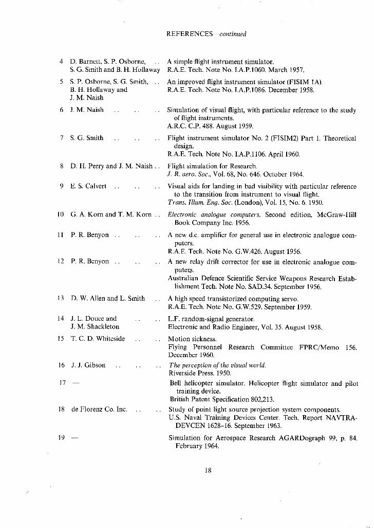
REFERENCES--continued
4 D. Barnett, S.P. Osborne, .. S. G. Smith and B. H. H'ollaway
5 S.P. Osborne, S. G. Smith, .. B. H. Hollaway and J. M. Naish
6 J .M. Naish . . . . . .
7 S.G. Smith . . . . . .
8 D.H. Perry and J. M. Na i sh . .
9 E.S. Calvert . . . . . .
10 G.A. Korn and T. M. Korn ..
11 P .R. Benyon . . . . . .
12 P .R. Benyon . . . .
13 D.W. Allen and L. Smith
14 J .L. Douce and J. M. Shackleton
15 T . C . D . Whiteside
16
17
J. J. Gibson ..
18 deFlorenz Co. Inc.
19
A simple flight instrument simulator. R.A.E. Tech. Note No. I.A.P.1060. March 1957.
An improved flight instrument simulator (FISIM 1A). R.A.E. Tech. Note No. I.A.P.1086. December 1958.
Simulation of visual flight, with particular reference to the study of flight instruments.
A.R.C.C.P. 488. August 1959.
Flight instrument simulator No. 2 (FISIM2) Part 1. Theoretical design.
R.A.E. Tech. Note No. I.A.P.1106. April 1960.
Flight simulation for Research. J. R. aero. Soc., Vol. 68, No. 646. October 1964.
Visual aids for landing in bad visibility with particular reference to the transition from instrument to visual flight.
Trans. Illum. Eng. Soc. (London), Vol. 15, No. 6. 1950.
Electronic analogue computers. Second edition, McGraw-Hill Book Company Inc.. 1956.
A new d.c. amplifier for general use in electronic analogue com- puters.
R.A.E. Tech. Note No. G.W.426. August 1956.
A new relay drift corrector for use in electronic analogue com- puter.s.
Australian Defence Scientific Service Weapons Research Estab- lishment Tech. Note No. SAD.34. September 1956.
A high speed transistorized computing servo. R.A.E. Tech. Note No. G.W.529. September 1959.
L.F. random-signal generator. Electronic and Radio Engineer, Vol. 35. August 1958.
Motion sickness. Flying Personnel Research Committee FPRC/Memo 156. December 1960.
The perception of the visual world. Riverside Press. 1950.
Bell helicopter simulator. Helicopter flight simulator and pilot training device.
British Patent Specification 802,213.
Study of point light source projection system components. U.S. Naval Training Devices Center. Tech. Report NAVTRA-
DEVCEN 1628-16. September 1963.
Simulation for Aerospace Research AGARDograph 99, p. 84. February 1964.
18

20 J.V. Roberts . . . .
21 W.F . Coulshedand .. A. G. Barnes
22 G. Hellings and E. T. Emms ..
23 R.,E. Jones, J. L. Milton . . and P. M. Fitts
24 J .E. Carrington and . . H. Martin
25 Redifon, Ltd . . . . .
26 J .K. Zbrozek and .. D. M. Ridland
.. The Short helicopter simulator for pilot training in elementary instrument and operational flying.
Short Bros. & Harland Ltd., Brochure No. RD105. April 1957. (See also : British Communications and Electronics. September 1957).
.. An improved display for the flight simulator• English Electric Aviation Ltd. Aircraft Division Flight simulation
Technical Note No. ASV/G/135. April 1959. (See also 'Electronic Engineering'• July 1960).
A visual system for flight simulators. British Communications and Electronics. May 1960.
An investigation of errors made by pilots in judging the attitude of an aircraft without the aid of vision.
U.S. Army Air Forces• Air Material Command Engineering Division Memo. Report No. TSEAA-694-13.
.. Rocking cockpit simulator development report. Test Report No. 280.
Short Bros. & Harland Ltd., Special Products Department•
•. Three axis movement system for a flight simulator• Specification C.7816. Issue 5.
. . A measured power spectrum of the vertical component of atmo- spheric turbulence.
A.R.C.C.P.522. March 1960.
19
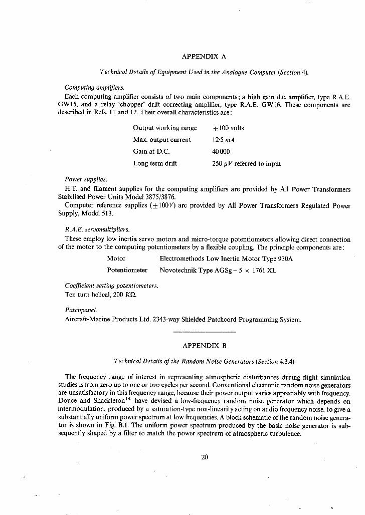
APPENDIX A
Technical Details of Equipment Used in the Analogue Computer (Section 4).
Computing amplifiers. Each computing amplifier consists of two main components; a high gain d.c. amplifier, type R.A.E.
GWl5, and a relay 'chopper' drift correcting amplifier, type R.A.E. GW16. These components are described in Refs. 11 and 12. Their overall characteristics are:
Output working range
Max. output current
Gain at D.C.
Long term drift
± 100 volts
12-5 mA
40 000
250 #V referred to input
Power supplies. H.T. and filament supplies for the computing amplifiers are provided by All Power Transformers
Stabilised Power Units Model 3875/3876. Computer reference supplies (±100V) are provided by All Power Transformers Regulated Power
Supply, Model 513.
R.A.E. servomultipliers. These employ low inertia servo motors and micro-torque potentiometers allowing direct connection
of the motor to the computing potentiometers by a flexible coupling. The principle components are :
Motor Electromethods Low Inertia Motor Type 930A
Potentiometer Novotechnik Type AGSg- 5 x 1761 XL
Coefficient setting potentiometers. Ten turn helical, 200 Kf~.
Patchpanel. Aircraft-Marine Products Ltd. 2343-way Shielded Patchcord Programming System.
APPENDIX B
Technical Details of the Random Noise Generators (Section 4.3.4)
The frequency range of interest in representing atmospheric disturbances during flight simulation studies is from zero up to one or two cycles per second. Conventional electronic random noise generators are unsatisfactory in this frequency range, because their power output varies appreciably with frequency. Douce and Shackleton 14 have devised a low-frequency random noise generator which depends on intermodulation, produced by a saturation-type non-linearity acting on audio frequency noise, to give a substantially uniform power spectrum at low frequencies. A block schematic of the random noise genera- tor is shown in Fig. B.1. The uniform power spectrum produced by the basic noise generator is sub- sequently shaped by a filter to match the power spectrum of atmospheric turbulence.
20
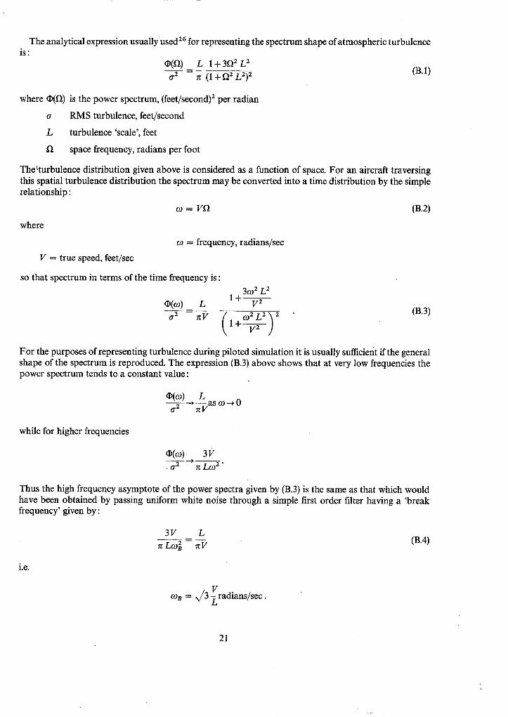
The analytical expression usually used 26 for representing the spectrum shape of atmospheric turbulence is:
O(f~) L 1 + 3f~ 2 L 2 a ---T- = 7r ( l+ f~ 2 L2) 2 (B.1)
where O(f~) is the power spectrum, (feet/second) 2 per radian
a RMS turbulence, feet/second
L turbulence 'scale', feet
fl space frequency, radians per foot
The~turbulence distribution given above is considered as a function of space. For an aircraft traversing this spatial turbulence distribution the spectrum may be converted into a time distribution by the slmple relationship :
where
co = Vfl (B.2)
co = frequency, radians/sec
V = true speed, feet/sec
so that spectrum in terms of the time frequency is:
O(o) L O-2
3 0 2 L 2 I + - - V 2
0 2 L 2 '~ 2 rcV ( 1 + ~ / " (B.3)
For the purposes of representing turbulence during piloted simulation it is usually sufficient if the general shape of the spectrum is reproduced. The expression (B.3) above shows that at very low frequencies the power spectrum tends to a constant value:
0(09) L o" 2 ~ ~-Vas co ~ 0
while for higher frequencies
0 ( o ) 3V 4 - - -
• o .2 rc Zco 2 "
Thus the high frequency asymptote of the power spectra given by (B.3) is the same as that which would have been obtained by passing uniform white noise through a simple first order filter having a 'break frequency' given by:
3V L ~r LCOB 2 rW (B.4)
i.e.
V con = x/3 ~radians/sec.
21

The turbulence scale which has generally been used in the past is L = 1000 feet. Three filters, having the characteristics given below, are available on each of the noise generators, corresponding to the flight regimes of landing, low speed flight in VTOL aircraft, and high speed flight, respectively.
Spectrum
A B C
Filter o~B rad/sec
0.33 0.10 1.76
Aircraft speed for L = 1000 ft
112 kt (190 f/s) 34 kt (58 f/s)
600 kt (1020 f/s)
Fig. B.2 shows a comparison between the measured power spectrum of the noise generator output (for spectrum A), the theoretical power spectrum, obtained by passing uniform white noise through a first order filter with the given break frequency, and the atmospheric turbulence 'model' spectrum given by equation (B.3). In practice it was found necessary to include additional high and low pass filters in order to maintain the d.c. level at zero, and to achieve the desired fall off in power at the higher frequencies. This was presumably due to the departure in shape of the pre-filtered noise spectrum from its ideal form, and accounts for the discrepancies between the theoretical and measured spectra shown in Fig. B.2.
Although it is recognized that this turbulence generator produces outputs which only roughly corre- spond to the measurements of real atmosphere turbulence, it has proved entirely satisfactory for piloted handling studies. More care might be needed, however, when using it with completely automatic equip- ment.
The same generators have also been used for simulating other random noises; for instance, wheel rumble when the aircraft is rolling along the runway.
APPENDIX C
Technical Details of the Enoine Noise Generator (Section 5.3).
A block schematic diagram of the engine noise generator is shown in Fig. C.1. The output has two components, a 'note' frequency, which varies, in both amplitude and frequency, with the input from the simulator (i.e. with thrust), and a background 'roar' which is varied only in amplitude. This empirically derived, and fairly simple, representation of the noise of a jet engine is found to be very effective in practice. The measured power spectra at minimum and maximum output are shown in Fig. C.2.
APPENDIX D
Technical Details of the Pitch, Roll and Azimuth Servos Used to Drive the Skyscape Projector Display (Section 6.1)
Type of drive. Pitch and roll servos: These are both position servos using d.c. armature driven motors, d.c. tacho-
generators for velocity damping and d.c. potentiometers for position feedback. Amplifiers were built up from standard computing amplifiers to sum the errors which were then fed into transistorised power output stages to drive the motors.
22

Azimuth servo : This is a 400 c/s position servo slaved by a synchro link to the yaw integrating servo (Section 4.2). A two phase motor-tachogenerator unit is used to drive the load through a gear train. The amplifier for this axis was a self contained high gain transistorised a.c. amplifier as used in the Redifon integrating servo equipment.
Limits o f movement.
The pitch and roll servos are limited in travel by micro switches which prevent the drives from reaching the mechanical stops but allow reversal out of the limit.
The azimuth servo is capable of continuous rotation.
Range of movement Max. rate Resolution Load "iner}ias
(approx.) Loop gain
Frequency response
Gear ratios
Motor : load Motor : position
feedback Motor : velocity
feedback
Pitch Roll
4-35 ° 125°/sec ±0.1 ° 450 x 10 a gm cm 2 32 volts at motor per degree error
Fig. D.1
215 : 1
5 . 3 :1
1-5 :1
d: 50 ° 200°/sec ±0.1 ° 250 x 103 gm cm 2 63 volts at motor per degree error
Fig. D.2
155 : 1
4 ' 1 : 1
2 : 1
Azimuth
Continuous 80°/sec ±0-1 ° 100 × 10 3
g m c m 2
800 volts RMS 400 c/s across motor field coils in series per de- gree error Fig. D.3
408 :,,1
9 0 : 1
1 : 1
Components used
Pitch and roll servos.
Motors Pullins 12 volt d.c. permanent magnet. Size 15 Rated torque 250 gm cm at 5000 RPM Stall torque 900 gm cm No load speed 7800 RPM Rotor inertia 25 gm cm 2
Tachogenerators Pullins 12 volt d.c. permanent magnet (motor). Size 08 Output approx. 1 volt/1000 RPM Rotor inertia 3.4 gm cm a
Position feedback potentiometers.
Pitch: Beckman 10 turn series 7223. Resistance 30 KY~ Wire turns 5923. Centre tapped
Roll: Colvern 15 turns Type CLR 26/1501/15 Resistance 30K Wire turns approx. 15000
23

Azimuth servo. Motor/tacho:
Synchro:
Muirhead 400 c/s 2 phase type 11M10E4 Control winding 26/13 volts Reference winding 115 volts Rated torque 29 gm cm at 3000 RPM Stall torque 45 gm cm No load speed 5600 RPM Tacho output 0.6 volts/1000 RPM Combined rotor inertia 1.3 gm cm 2 Smiths control transmitter ACS/2/AM 26/11.8 volts. Rotor/stator Phase lead at max. coupling 6 deg
APPENDIX E
Technical Details of the Roll Servomechanism Used in the Contact Analogue Display (Section 6.4).
Type of drive :
Inertia of coil assembly : Motor : Feedback potentiometer :
Tachogenerator : Loop gain : Static positioning accuracy Max. rate of roll (measured) Max. roll acceleration (measured) Frequency response
Position servo using a d.c. motor, potentiometer position feedback and tachogenerator velocity feedback. Gear drive throughout using anti-backlash split spur gears. 6000 gm cm 2 (approx.) about rotational axis. Pullin size 15 P.M., 12 volts d.c. geared 150:1 to the coil assembly. Computer Instruments Corporation Type 105. Carbon film track, single turn. Alternative gearings 1:1 and 1:10 to the coil assembly. Pullin size 18 P.M., geared 60:1 to the coil assembly. 28 volts at motor terminals per degree of position error. ±0.1 deg 205 deg/sec 4100 deg/sec z See Fig. E.1
APPENDIX F
Technical Details of the Closed Circuit Television Visual Simulation System (Section 6.5).
Camera channel:
Field of view:
Picture quality:
Marconi Mk.III monochrome
50 deg in azimuth, 35 deg in elevation.
Errors in linearity, less than 1.5 per cent of height or width. Errors in geometry, less than 2.5 per cent departure from the ideal rectangle. Resolution/depth of field. When viewing a test card comprising a uniform grid of black and white bars, whose black bar centres subtended 10 minutes of arc at the camera, the depth of modulation at the centre of the displayed picture was greater than 20 per cent for the following combinations of near and far points.
24

Model distance inches
Near point
1.81 2.83 3.87
Far point
3"36 10.17 184-0
Full scale. 1:700 feet
Near Far point point
106 196 165 593 226 10750
Full scale. 1:2000 feet
Near point
302 471 645
Far point
560 1690
30600
Model area :
Viewing range:
Height range :
Servo performance:
Two models on endless flexible bands each 35 ft long by 10 ft wide, one to a scale of 1:700 and the other to a scale of 1:2000.
1:700 model. 1.4 nm ahead and 0.175 nm rearwards. 1:2000 model. 4 nm ahead and 0.5 nm rearwards.
1:700 model. 7 ft up to 600 ft. 1:2000 model. 15 ft up to 1500 ft.
Translational servos. The translational servos may be operated either as integrators or as positional slaves. The following components of aircraft motion can be re- presented.
Component of motion
Parallel to the model major axis (belt drive)
Parallel to the model minor axis (transverse drive)
Normal to the model (height)
Max. velocity
±400 ft/sec
± 300 ft/sec
± 100 ft/sec
Max. acceleration
± 50 ft/sec 2
± 30 ft/sec 2
± 120 ft/sec ~
In the positioning mode the static positioning accuracy at the datum point is:
Direction 1:700 scale model 1:2000 scale model
Along the model major axis
Along the model minor axis
Normal to the model
± 4 f t
± 2 f t
±0.25 ft
± 8 f t
± 4 f t
i l f t
The static positioning accuracy away from the datum point is within 0.5 per cent of the demanded value, unless this is less than the values given above.
When used as integrators the velocity servos can be set up to give an integrating accuracy of -+-1 per cent of the dornanded speed for inputs between full scale and 1/250 of full scale, this accuracy being maintained over a 4 hour period.
Rotational servos. The rotational servos have the following characteristics. They are operated only as positional slaves.
25
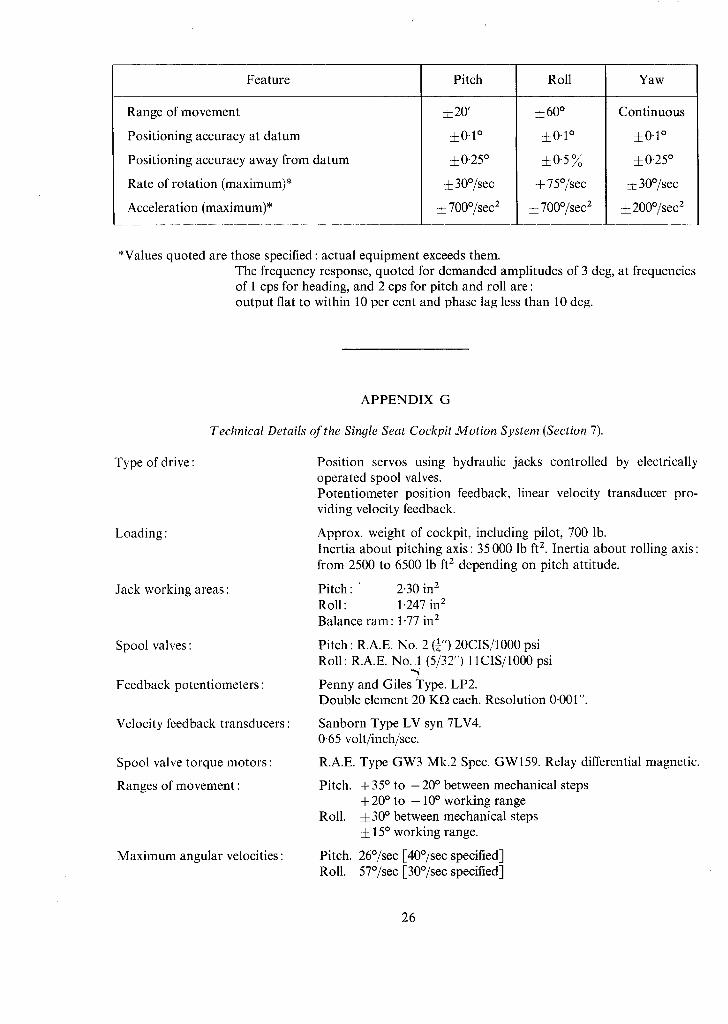
Feature Pitch Roll Yaw
Range of movement
Positioning accuracy at datum
Positioning accuracy away from datum
Rate of rotation (maximum)*
Acceleration (maximum)*
_20 '
±0.1 °
±0.25 °
± 30°/sec
± 700°/sec 2
±6 0 °
±0.1 °
±0.5%
± 75°/sec
±700°/sec 2
Continuous
±0.1 °
±0'25 °
± 30°/sec
±200°/sec z
*Values quoted are those specified : actual equipment exceeds them. The frequency response, quoted for demanded amplitudes of 3 deg, at frequencies of 1 cps for heading, and 2 cps for pitch and roll are : output flat to within 10 per cent and phase lag less than 10 deg.
APPENDIX G
Technical Details of the Sinyle Seat Cockpit Motion System (Section 7).
Type of drive:
Loading :
Jack working areas:
Spool valves :
Feedback potentiometers :
Velocity feedback transducers:
Spool valve torque motors:
Ranges of movement :
Maximum angular velocities :
Position servos using hydraulic jacks controlled by electrically operated spool valves. Potentiometer position feedback, linear velocity transducer pro- viding velocity feedback.
Approx. weight of cockpit, including pilot, 700 lb. Inertia about pitching axis: 35 000 lb ft 2. Inertia about rolling axis: from 2500 to 6500 lb ft 2 depending on pitch attitude.
Pitch : ' 2.30 in 2 Roll: 1.247 in 2 Balance ram: 1-77 in z
Pitch: R.A.E. No. 2 (¼") 20CIS/1000 psi Roll : R.A.E. No. 1 (5/32") 11CIS/1000 psi
Penny and Giles Type. LP2. Double element 20 Kf~ each. Resolution 0.001".
Sanborn Type LV syn 7LV4. 0.65 volt/inch/sec.
R.A.E. Type GW3 Mk.2 Spec. GW159. Relay differential magnetic.
Pitch. + 35 ° to - 20 ° between mechanical steps + 20 ° to - 10 ° working range
Roll. ± 30 ° between mechanical steps ± 15 ° working range.
Pitch. 26°/see [-40°/sec specified-] Roll. 57°/sec [30°/sec specified]
26

Maximum angular accelerations:
Max. declerations in the event of a se rvomotor runaway
Frequency response :
Pitch. 160°/sec 2 [1O0°/sec 2 specified] Roll. 390°/sec 2 [100°/sec 2 specified]
Pitch. 300°/sec 2 [600°/sec 2 specified] Roll. 700°/sec 2 [300°/sec 2 specified]
See figures G1 and G2. [-Specified phase lag: less than 15 ° at 1 cps for ± 2 ° sinusoidal inputs]. Min imum phase lags achieved under these condit ions : Pitch. 35 ° Roll. 30 ° .
/
27

tO O0
\ .u
FXG. 1. Rudimentary simulator cockpit used before the rebuild.
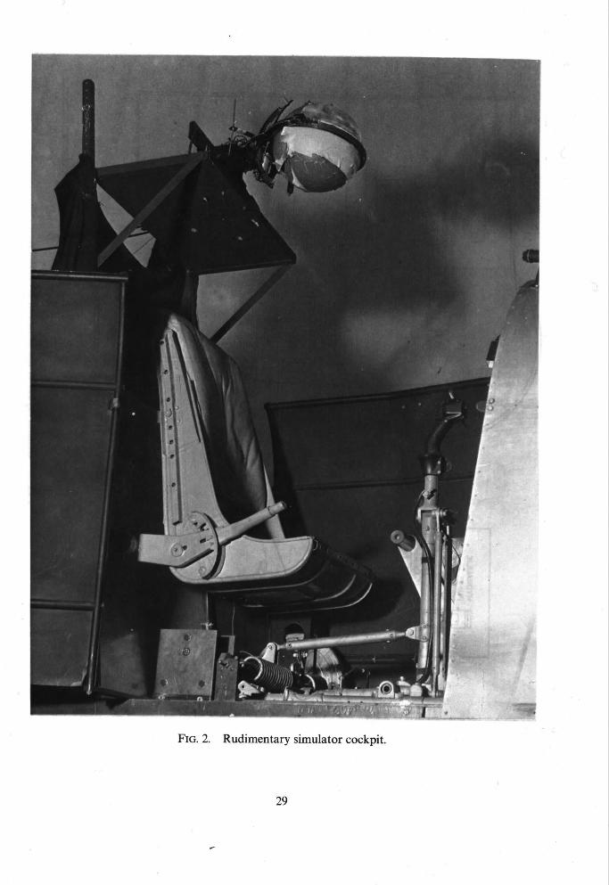
J .
i~ ̧~ /
Ill
FIG. 2. Rudimentary simulator cockpit.
29
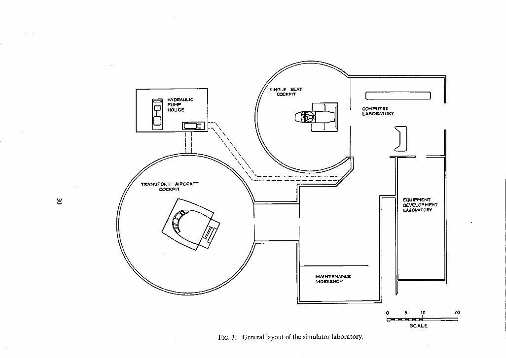
, r ~ ~ : , // --r-v- 4 I I \ \ \ \ \ I I \ \ \ \
' , ~ , , ____~_~
-_-_-_-_-_~i_-_- = _--_-/ 1
COHPUTEI~ LAI~ORAT OIlY
EQUIPPIEhlT DEVELOPHEblT LABOleATORV
0 5 I0
SCALE
z0 I
FIG. 3. General layout of the simulator laboratory.

FIG. 4. Exterior view of the simulator laboratory.

ELECTRONIC EQUIPHEWr FOR VISUAL~ DISPL:A¥S, ETC. VISUAL DISPLAY PRO:TECTOR
COGKPn" ~
3O~'t DIA SCREEN FOR ~/ISUAk DISPLAYS
COCKPIT HOVING \ HECHANISM
ELECTRONIC ANALOGUE COPIPLITER
COHPUTING SERVOS
RECORDER
l:
COHTROk DESK
J
FIG. 5.
0 5 I0 ~ ,--I I
SCALE
Layou t of single seat cockpit and computer laboratory.
HOVING ~ 3'ACKNNNN~
ELLIPTICAL ~ ~ / l - - ~ ~R~CtI~ ~ , S C R E E N ~ n /
ANALOGUE COHPLiTE%
" l l l i l l l l l l l lo o l l l l l l l i l l l l l l l l l I I I I I l l l l t lo olllll I I I I I I I I I I l l H'ff]H.].]~
~ l l l l l l l l l l l l l l i i l i i i i i i i l l l l l I " 1 - 1 1 1 1 1 1 1 1 1 1 1 1 1 1 1 1 ~ I--I-'III II I I III I I IIII;~ iliil ; I II II
lioo,~oollool Io 011o ollo o t ~ I1o o111o olllo oil lid olllo olllo o1110 ,lllo ollto oll I I I I I I I I i ! I
0 5 I0 I.--,,---i,---.I f
SCALE
FIG. 6. Side elevation of single seat cockpit and computer laboratory.
32

0 0 5 9 0 ~ 7 ~
ELLI PT ICAL SCREEN
SPHERICAL DISPI.AY
SCREEN ,40.~t DIA
DUAL CONTROL
COCKPIT
OI.~PLAV
COCKPIT MOVING MECHANISM
FIG. 7. Side elevation of transport aircraft cockpit.
0 5 I0 ~ ~ I
SCALE
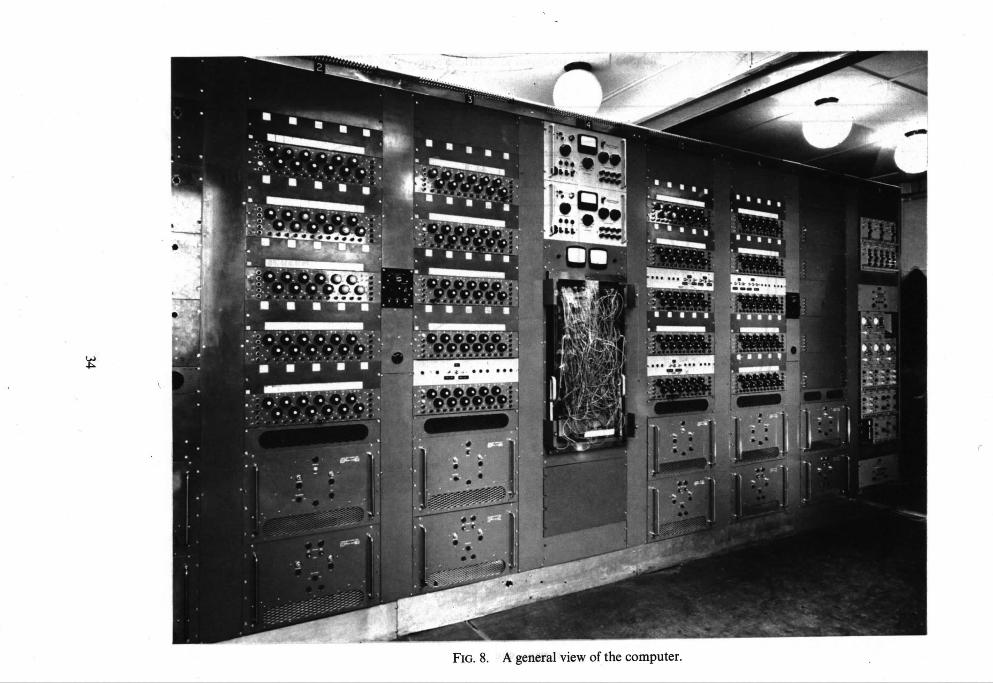
11
• !
~ - • • o ~ e e o e o e a n e m i a qP !
¢
e , •
. d
¢ I"
o ~
" . . , , . T . , , . . , .
F -
,1i f i . J
"1 '
• ,~ ; , , ; ' . . : . . . . . .
FIG. 8. A general view of the computer.

t ~
FIG. 9. Instrument panel in the single seat cockpit.

O~
FIG. 10. Centre stick control layout in the single seat cockpit.

L ~
FIG. 11. Control wheel layout in the single seat cockpit.

ta~ OO
FIG !2. Controls and instrument panels in the two seat cockpit.

CONTROL HYDRAULIC SUPPLY REGULATED TO \1 STICK CONSTANT PRESSURE BY HOSSON .
FEEL UNIT CONTROLLER [.NOT SHOWN)
~"~'~ \ \~ ~',,,.~ KNUCKLE / / / FEEL UNIT HYDRAUL,C .,TACK
_ IT
'q ~ '; ~ JACK FORCE .o -ON~R \'~ [ //ACTS THROUGH STICK
MED
M
~ R I ~ Ac'rUATOR HOVE5 ~ (C) STICK DEFLECTED, FORCE RETRIMMED ] TRIMMING ARM UNTIL ,.TACK FORCE
A~AIN ACT5 "THROUGH STICK PIVOT
FIG. 13a to c. Diagram showing operation of the control feel system.
39
~ J
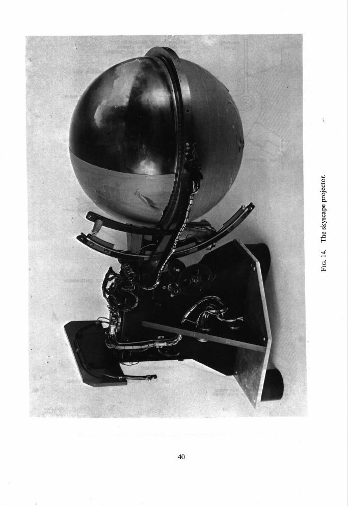
Q
q~
~k
40

4~
? ,
FIG. 15. Visual scene of horizon and clouds produced by the 'Skyscape' projector.

4,
t O
FIG. 16. The runway shadowgraph projector.
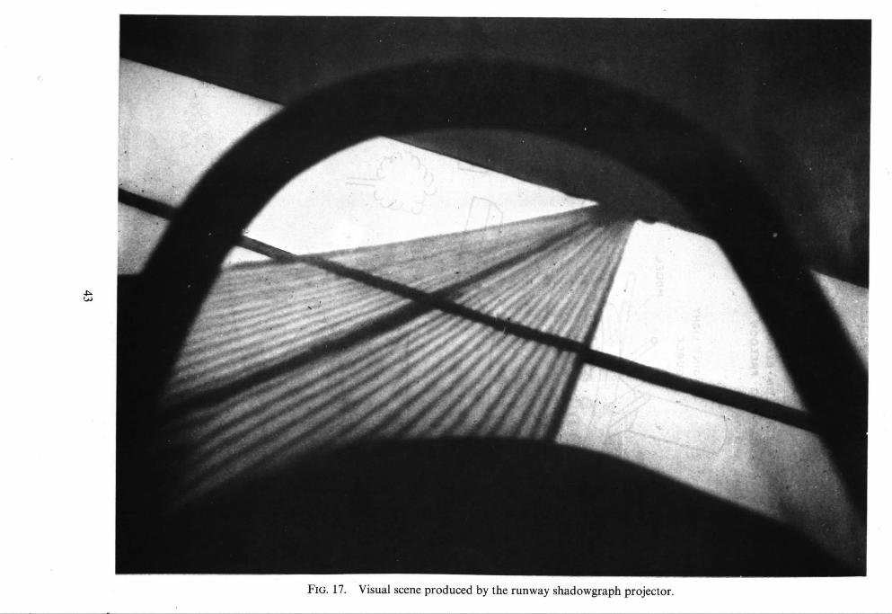
4 ~ k ~
0
" ~ o
7 ¸¸
! ,
FIG. 17. Visual scene produced by the runway shadowgraph projector.

PITgH) ROLL ANO YAW
- , / /
FIG. 18. Principle of operation of VTOL shadowgraph projector.
44

o
d
FIG. 19.
"k ̧ ;~'"
Visual scene produced by a mock-up of the VTOL shadowgraph projector.
45
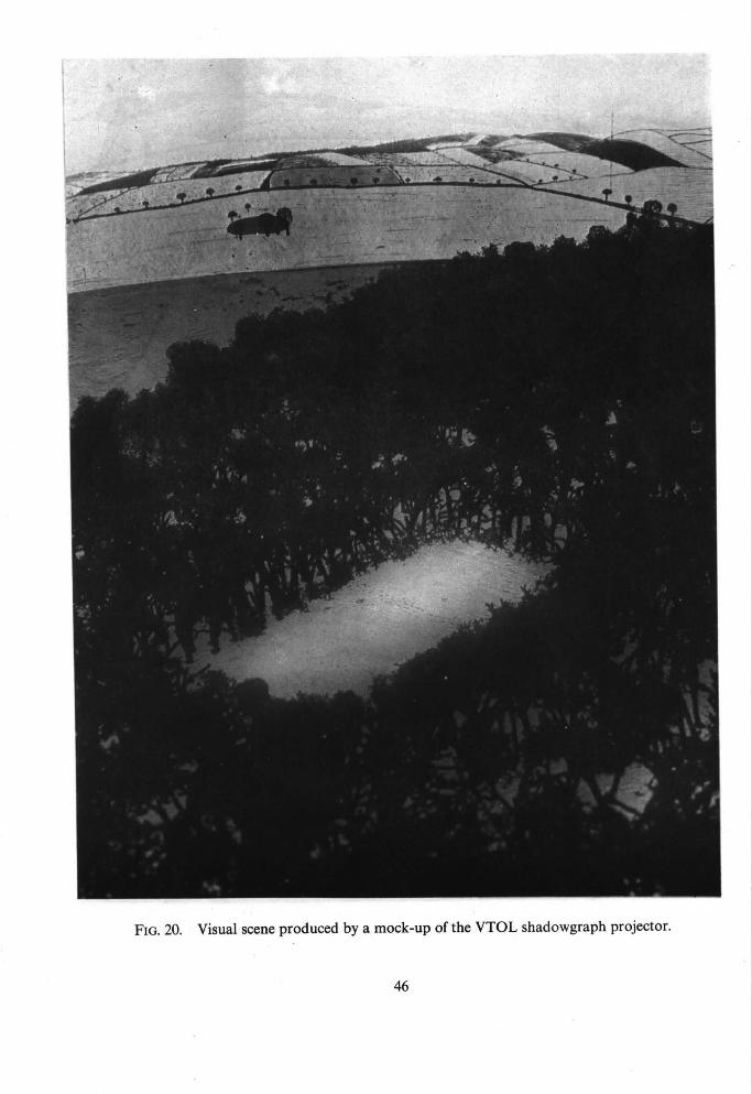
FIG. 20. Visual scene produced by a mock-up of the VTOL shadowgraph projector.
46
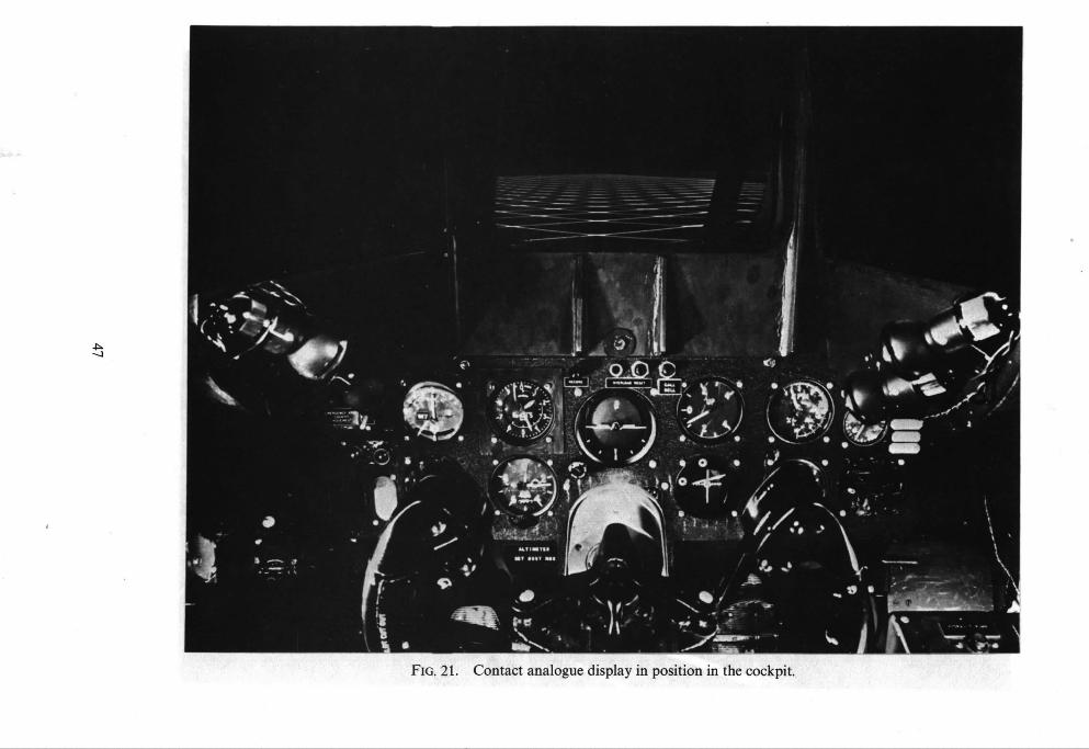
4~
FIG. 21. Contact analogue display in position in the cockpit.

~,~
~ 2
' ~i
FIG. 22. Camera and airfield model used for closed circuit T.V. visual simulation system.
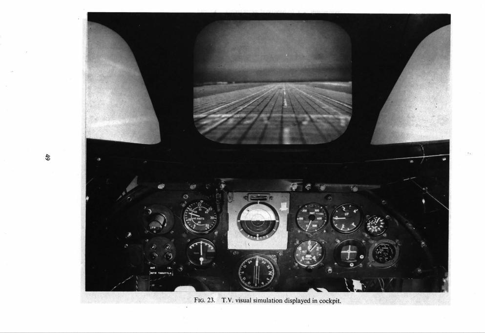
-7"
- . <
FIG. 23. T.V. visual simulation displayed in cockpit.

FIG. 24. Visual scene produced by T.V. simulation.
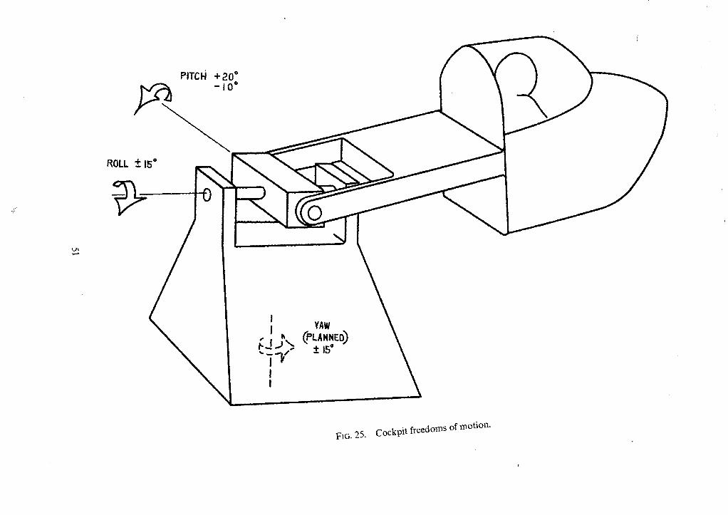
ROLL
PITCH + 20" ,~ -I0°
+- 15"
I I
"' i 'Y I !
YAW (PL^..~o)
± 15"
FIG. 25. Cockpit freedoms of motion.

- . " " : t ; : -
I l l
L~ Ix9
FIG. 26. The single seat cockpit and motion system.

v . ~ 3 . ~ : . . ~ '
? , . . . . . . .
. - . .
2
L%
J ° ,
° l
FIG. 27. The transport aircraft type cockpit and its motion system.
53

NOISE SOURCE
I I i A-.-,. ,=. i
I BANDPASS I FI LTER
FIG. B2.
AMPLI FI ER
SATURATION TYPE
NON - LIN EARITY
+3OV LIMIT - ~
-3OV LIMIT -~
,~PECTRUM FILTERS
SPECTRUM A [
SPECTRUM S
SPECTRUM C [
SELECTOR SWITCH
i
ou.,u, I AMPLIFIER
FIG. B1. Block schematic of random noise generators.
6 .0 ' i" 3 ~ z L ~ '
---.. /~(@= L ' I+"T~ -----..~. / " ~ ~ ~ ,
~..._..../ t~ +'~' - )
0-50 N UNIFORM WHITE NOISE / I~X" ~ /MEASURED SPECTRUM PASSED THROU~IH A / I \ '~ I ' ~ FROM SIMULATOR
--~1o FIRST ORDER FILTER [ ~1 \ NOISE GENERATOR
~ O . 1 ~
~ °'0~'
J ~ b
\ FtRST OROER FILTER • \ , BREAKPOINT ~)B tO,378 ~'ad/sec \ ~.\
; \ X", 0'001
o.o i o . o s o . t o , 5 i . o e . o io.o
FREQUENCY l"od/sec Comparison of theoretical and measured noise generator output with 'model' atmospheric
turbulence.
54

J VARIABLE FREQUENCY I
NOTE I GENERATOR INPUT VOLTAGE t FROM SIMULATOR
l . >
NOISE SOURCE
I VARIABLE I
VARIABLE ~_~ GAIN AMPLIFIER
GAIN t ~ AMPLIFIER
I SUMMER AUDIO POWER
AMPLIFIER
OTHER NOISES
TYRE SQUEAL AND WHEEL
RUMBLE
COCKPIT SPEAKER
COCKPIT SPEAKER
FIG. C1. Block schematic of engine noise generators.
70
~ 6 0 z
< I11
• ~ 50 ILl to b .< z <~ 40
MUIRHEAO- PAMETRADA TYPE D4-89- EM
I FULL TH RUST,~.,J / (,oo~
/
F - I /
S
NOTE FREQUENCY FUN DAME N TAL
IDLING THRUST ZERO INPUT
I0 IO0 I 0 0 0 FREQUENCY -- C. RS.
I0 000 fO0 000
FIG. C2. Output spectrum of engine noise generator.
55
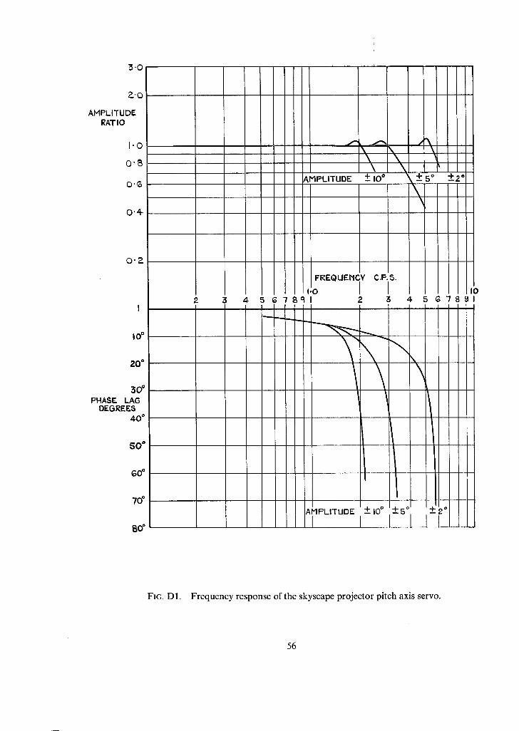
3.0
?-'0
AMPLITUDE RATIO
I 'O
O'B
O.~o
0"4-
0 , 2
i o =
20"
3 O °
PHASE LAG DEGREES
40"
SO"
GO"
70'
BO °
£ 3 ~- 5 G 7 8 9 I 2 3 4- 5 co
\
AMPLITUDE I +__,oo I+,o I - ,o I I - I I
) " / 8 9 1
FIG. D1. Frequency response of the skyscape projector pitch axis servo.
56

I ' 0
0 ' 8
0"~
~.'0
AHPLITLIDE RATIO
0"4
0"2-
4 I
=d
2o"
PHASE LAG DEGREES
4 0 °
so"
so °
7o °
e6
2 3 5 G" / 8 9 1 4 5 G 7 8 9 1
B'O
\ \ \
"k \
\
/ \,
;ol AMPLITUDE 4"1 "1"5"
I +-2"
FIG. D2. Frequency response of the skyscape projector roll axis servo.
57

3 '0
~ ' 0
AMPLITUDE RATIO
I ' 0
0 "8
0'~o
0 ' 4
O'P-
o*
I0"
2o*
3o* PHASE LAS DESREF_&
~rO °
5 0 °
6 0 °
70"
8 0 °
I
2 3
| | |
I
I I I l l l l ' O zk 5 ~7891
+_ 9 °
)
+-3"6
i
FR£QUENCY C.P.S.
I I I 2 3 4-
SS.P. AZ. SERVO
~J" + AZ. SERVOS
\
V i
I -8"
+ 3.6 i I
SYNCRO LINK
1-8"
J I ! I I
I0 67891
FIG. D3. Frequency response of the skyscape projector azimuth servo.
58

~0
PHASE LAG
0
~ ~ THEORETICAL PHAGE LAG
50 " ~ , ~ ' ~
10 °
15 °
20 a
HEASURED PHASE LAGS FOR VARIOUS ROLL AHPLITUOES
\ \
0"2 0"5 1.0 ~-0 3"0 ~.-0
FREQUENCY C.P.S.
AMPLITUDE RATIOS WERE WITHIN I% OF UNITY OVER THE MEASURED RANGE~EXCEPT AT 2.75 AND 3"0 C.P.S. FOR "1" 4-5 ° WHERE THEY WERE 1.05 AND 1.05
FIG. El. Frequency response of the roll servomechanism used in the contact analogue display (Section 6.4).

:7
t J i
o ¢ .~
o
©
o "
>
'-o
O'x O
I i
2 ~
0 . . . .
- 2
- 4
0c -G
-10
0-2
0
ao*
40*
GO* . . J
<: 8 0 ° "-1- o . .
f0o*
I~.0*
0-2
FIG. G2a & b.
-15 6
4 % -PO
~ o - -- ¢ ~ \ ~
. 0 4 < I - - (
- I 0
0.5 1.0 ?-0 3.0
FREQUENCY CP~
- 1 2
\ \
° 1"5
1.0 o
-0.8
- 0 - 6 ,,, 0 I-
J - 0 . 4 fl-
0,2
(Q) A M P L I T U D E RESPONSE 0,2 0,5 1,0 ?-,0 5,0
FREQUENCY C.RS.
(o) A M P L I T U D E RESPONSE
0 _ NIG ~ I
. . . . 40 ' " ' ~ "
,w~% ~ 6o' ,, 80 '
120"
O. 140*
O- I-0 2-0 3-0 160 ° ~ "~
FREQUENCY CPS ~ " 180 °
(b) PHASE RESPONSE
Frequency response of the cockpit moving
mechanism for rolling motion.
0 .2 0 .5 1.0 2 '0 9"0 I:I~EQUENCY C.P.S.
( b ) P H A S E RESPONSE
FIG. Gla & b. Frequency response of the cockpit moving
mechanism for pitching motion.

R° & M° No, 3566
~(! Crown copyright 1969
Published by HER M~OES'rV's SIAHONERY OFFICE
To be purchased from 49 High Holborn, London w.c.1
13A Castle Street, Edinburgh 2 109 St. Mary Street, CardiffcF1 1JW
Brazennose Street, Manchester M60 8AS 50 Fairfax Street, Bristol Bsl 3D~ 258 Broad Street, Birmingham 1
7 Linenhall Street, Belfast BT2 8AV or through any bookseller
R° & M. No° 3566
S.O. Code No. 23-3566.