aircraft mission and system failure - icas is
TRANSCRIPT
AIRCRAFT MISSION AND SYSTEM FAILURECONSIDERATIONS FOR FUNCTIONAL INDUCTION BASED
CONCEPTUAL ARCHITECTURE DESIGN
Michael Armstrong, Dr. Elena Garcia, and Dr. Dimitri MavrisAerospace Systems Design Lab, Georgia Institute of Technology, Atlanta, GA
Keywords: Requirements Emergence, Performance Degradation, Load Shedding
Abstract
With current advances in system-level tech-nologies, changes in system level aircraft re-quirements, and outsourcing of technology de-velopment, architecture innovation and integra-tion have become driving differentiators betweencompeting aircraft concepts. Revolutionary con-ceptual vehicle systems architectures promise ad-ditional benefits over incremental improvementsachieved through technology insertion and sys-tem adaptation or evolution. However, explo-ration of the complex vehicle systems architec-ture design space introduces unique challengesin the definition and allocation of sizing criticalunit and platform level requirements. Sizing crit-ical performance requirements are infrequentlyderived from normal operating conditions butrather emerge from responses to system failures.This paper explores means for the identifica-tion and allocation of architecture specific off-nominal operating mode requirements throughthe extension of traditional hazard assessmenttools, performance degradation optimization, andthe propagation of function/criticality require-ments through structured functional dependen-cies.
1 Introduction and Motivation
Current and future aerospace performance de-mands have increased the aerospace commu-nity’s interest on enhanced vehicle systems op-timization and integration. Electrical systems
have been shown to provide potential for largeincreases in the efficiency of performance andmaintenance. However, the application of highpower, safety critical technologies in the aircraftsubsystem architecture introduces interesting in-tegration challenges, and requires a redefinitionof the generally accepted and well understoodsystems relationships [21]. While much workhas been done toward incremental improvementof individual technologies and subsystems, thereis natural resistance to solve the problem at thewhole aircraft level [4]. Complex systems designdoes not pose contained and well-formed prob-lems but "messy, indeterminate situations [19]."
Next generation aircraft subsystem architec-ture concepts must integrate these promisingtechnologies in order to achieve a maximum ben-efit. The architecture provides the frameworkfor further development, regulates relationshipsbetween stakeholders, and manages the flow ofrequirements necessary to size each system andhardware. Therefore, adoption of the best sub-system architecture concept has a critical strate-gic importance.
In order for an architecture concept to beselected for further development, analysis mustshow that it proves superior to other conceptualarchitectural alternatives. The architecture alter-natives must be sized and compared based ontheir effectiveness in fulfilling requirements.
As expressions from the intentional and be-havioral domains, vehicle systems requirementsmust qualify the system’s ability to achieve goals
1

MICHAEL ARMSTRONG, DR. ELENA GARCIA, AND DR. DIMITRI MAVRIS
Min: Platform Level Objective Function= fEval(UnitAttr)
UnitAttr =
AttrUnit1AttrUnit2
...
s.t.: PHazard(F)−PMaxLimit(F)≤ 0
Load Alloc. =
FG1Alloc.FG2Alloc.
...
∫ t
0Loadi (τ)dτ−E0n ≤ 0, i = [1,n]
(1)
and complete specified operations. However,the elicitation of sizing-critical requirementspresents difficulties during non-conventional ve-hicle systems concept architecting. Best prac-tices, axioms, and rules of thumb regarding theintegrated sizing of high power electrical sys-tems at the aircraft level are insufficient to war-rant architecture selection. Increased compo-nent and platform complexity yields require-ments which supervene due to complex behav-ioral relationships between the architecture’s fun-damental units. Many dominating requirementsemerge through architecture specific sizing criti-cal operating scenarios and unique performancedegradation or load shedding strategies.
Performance requirements necessitated byexceptional operating states often prove more siz-ing critical than requirements imposed by thestandard mission. Additionally, during archi-tecture design, the relationship between failurecauses and effects is often unclear [6]. Depend-ing on the structure and relationships of the ar-chitecture, specific events may have vastly differ-ent operational effects at the platform level. Off-nominal scenarios performed under architecturespecific load shedding strategies must be identi-fied to predict maximum unit and system levelrequirements during architecture trades.
This paper explores operational emergent re-quirements by addressing behavioral complexityin terms of operating mode and safety/reliability.Tools and strategies are introduced which deter-mine architecture specific performance degrada-tion strategies during the identification and appli-cation of requirements concurrent to vehicle sys-tem concept generation and trades.
2 Vehicle Systems Emergent Requirements
Aircraft vehicle systems design can be posed asthe optimization process depicted in equation 1.Designers configure the architecture by augment-ing unit attributes (UnitAttr) and allocating mis-sion loads for each functional group (FGAlloc) ina manner which can accomplish platform goalswhile minimizing some objective function ( feval- cost, weight, etc). For this design problem, theobjective function must take the form of vehiclesystem mission sizing, and the constraints act tolimit the probability of operational hazards andensure adequate energy on all storage elements.
Requirements definition traditionally pre-cedes concept design and is primarily driven bydesigner and stakeholder intent. During the re-quirements definition process the “problem space[10]” is described in terms of the fulfillment offunctions, the accomplishment of goals, and thesolving of problems. These objectives are in turntranslated into operational, functional, and phys-ical requirements which drive concept definition.
Not all requirements, however, can be definedprior to system definition. Derived requirementscannot be specified by the stakeholder, but are theresult of requirement decomposition and the ap-plication of expert knowledge and logical deduc-tion [13, 15]. The application of domain knowl-edge is often sufficient for conventional designexercises. However, with the introduction of rev-olutionary architecture concepts, experience canfall short in the accurate prediction of unit levelrequirements.
Michael Sinnett, chief engineer of systemsdevelopment for the Boeing 787 Dreamliner,spoke about the decision to change the cabinair pressurization method from engine bled to
2
Aircraft Mission and System Failure Considerations for Functional Induction Based ConceptualArchitecture Design
electrically compressed. This single conceptualchange to the aircraft architecture imposed mul-tiple dramatic changes to the predefined or as-sumed relationships within the system. Sinnettsaid:
“When we decided on electric pressurization,it lowered aircraft empty weight 1,000-2,000 lb.and fuel burn was down several percent, but thenumbers got muddied as the 787 got integrated.It’s hard to say where the weight has gone [3].”
Requirements definition for revolutionarycomplex vehicle systems architecture is a pro-cess which can produce “counter-intuitive, seem-ingly acausal behavior full of unpredictable sur-prises [2].” As new technologies and advancedarchitectures are introduced, new requirementsmay appear which “cannot be fully explainedmechanistically and functionally [8]” but requirean understanding of the intent, purpose, and, tosome degree, morality associated with the de-signs governing the derivation and application ofa requirement. Ontologically, these requirementsare emergent. They come into existence or be-come evident with specific architecture imple-mentations.
Emergence occurs when the properties of thesystem or object can only be derived from themicrostates or dynamics of parts of the system.These properties are not directly distinguishablefrom the structure property of the system/objector its parts and result from complex interactionsbetween the parts. Flake describes emergenceas “a property of a collection of simple sub-units that comes about through the interactionsof the subunits... Usually, the emergent behavioris unanticipated and cannot be directly deducedfrom lower-level behaviors [7].” Thus, emergentrequirements can not be enumerated or quanti-fied during the traditional requirements definitionprocess, but are the result of complex behavioralrelationships between units in specific architec-ture implementations.
Behavioral complexity of a vehicle systemsarchitecture can be characterized in multiple di-mensions: operating mode dependence, safetyand reliability dependence, and time dependence[14]. Time and operating dependence are ad-
dressed here in the context of the aircraft mis-sion. Additionally, designing for safety re-quires a complete understanding of the platformoperations, consequences to functional failures,and means towards ensuring adequate reliability.Thus, safety and reliability considerations inter-act with mission sizing through the definition ofoff-nominal operations which typically dominateunit and system level requirements.
2.1 Mission Analysis
Time dependence plays a role in defining archi-tecture requirements at multiple levels. Tradi-tional high level aircraft platform conceptual de-signers, tasked with life cycle and mission anal-ysis, apply timesteps on the order of minutes todecades. Conversely, unit and vehicle systemdevelopers must take a much finer time depen-dency perspective. To ensure adequate stabilityand power quality, power electronics and elec-tric machine designers may consider switchingand response rates on the order milliseconds orsmaller. Therefore, time dependence relates torequirements emergence through multiple means.
Sizing is primarily carried out at the missionlevel. Here, requirements emerge which definethe energy requirements of the system. Tradi-tional mission analysis uses mission simulationto define energy storage in the form of fuel. Thetotal block fuel requirement is the product of theintegral of fuel flow throughout every likely se-quence of operations. In considering the vehi-cle system, all energy storage requirements mustbe sized similarly. The amount of energy pro-vided available from ’n’ storage devices is con-strained by the amount of energy available asseen in equation 2. Load (τ) represents missionloading and E0 is the initial stored energy. Themax energy required on the unit determines nec-essary mass and volumetric attributes.
∫ t
0Loadi (τ)dτ−E0n ≤ 0, i = [1,n] (2)
The aircraft mission not only serves to defineenergy requirements for storage devices, it also
3
MICHAEL ARMSTRONG, DR. ELENA GARCIA, AND DR. DIMITRI MAVRIS
drives the magnitude of platform level require-ments. An operating mode can be defined as aparticular functioning condition or arrangementof a system. This includes the behavioral andphysical state of a system designated in responseto internal or external stimuli.
A fundamental understanding of the systemlevel operations is critical to the identification ofrequirements. Requirement/specifications are de-rived from the behavioral domain [9]. Jacobsonstates, “The very first model of a complex sys-tem should be a model that describes the system,its environment, and how it and its environmentare related... It should describe the system as itappears from the outside [12].” In order to de-termine accurate requirements, a robust under-standing of the sizing critical operating condi-tions must be attained.
Traditional Scenario-Based Design andModel-Based Systems Engineering tools providea framework for the definition of traditionaloperational scenarios. However, they fall shortin addressing the emergence of requirementsdue to inadequate coverage. Rolland et. al.express the limitation of scenario based designtechniques in providing sufficient “intentionalcoverage”: including the capture of goal depen-dence, problem, responsibility, and cause. Theywrite, “Intentional models are seldom includedin scenario approaches... They are, so to speak,implicitly underlying the interfaces betweenthe reengineering company and its environment[18].”
Furthermore, Allenby and Kelly providemore insight to these limitations. They state that“there is little guidance available for the system-atic identification of either ‘alternative paths’ or‘exceptional courses’ of events in scenario or use-case descriptions. Under these circumstances, thepractitioner is left with little assurance of suffi-cient coverage [1].”
While ETOPS or one engine out at take-offmay govern the attributes of some systems, theattributes of other units in the complex vehiclesystem may be more sensitive to other opera-tional states. Deviations from the nominal mis-sion pose sizing critical requirements on specific
units [14]. As discussed earlier, requirements aredirectly sensitive to designer or stakeholder in-tent. The inability of the traditional systematicobject based scenario identification tools to cap-ture intent limits their ability to generate architec-ture specific emergent sizing critical scenarios.
At any point during the nominal mission thereexists a probability that some deviation will oc-cur due to internal or external changes in ex-pected state (unit/system failure, weather, etc.).The aircraft behavioral response to this changein state represents a sequence of operating con-ditions branching from the nominal mission andarriving at a dissimilar final state. Furthermore,each deviation can exhibit additional changes tothe internal or external state which again branchfrom the deviation branch. These deviations de-termine the form of the objective function seen inequation 1.
In addition to external relationships with theenvironment, the internal system relationshipsshape the significance of “exceptional courses”of events. The dominance of the requirementsgenerated from each failure condition dependson the architecture implementation. Differentvehicle systems architecture concepts potentiallyyield different paths which drive architecture re-quirements.
Ensuring adequate response to exceptionalinternal states is typically enforced through theimposition of reliability constraints. Enforcingthese constraints and designing towards adequatesafety requires a complete understanding of thereliability implications of each architecture archi-tecture concept.
2.2 Safety and Reliability Requirements
In order to define the necessary reliability the de-signer must understand the operational impact ofa failure on the environment. The detrimentalimpact of failures is expressed in terms of oper-ational hazards. To specify safety requirementseach hazard category assigns a probability limitto the operational effect. This is done to controlrisk (“the frequency of an occurrence and the as-sociated level of hazard [22]”). Complete func-
4

Aircraft Mission and System Failure Considerations for Functional Induction Based ConceptualArchitecture Design
Fig. 1 Expanded Risk Bow-Tie for FunctionalFailures [23]
tional specification involves defining the magni-tude of the the required action or capability withan associated level of reliability.
There are multiple means by which the de-signer can ensure that the appropriate reliabilityis achieved. This occurs through fault preven-tion or fault tolerance. Risk can be mitigated atthe platform level through operational mitigationprocedures. It can be additionally mitigated atthe system level through “spatial and temporalredundancy [24]”. Furthermore, risk can be miti-gated at the equipment level by ensuring high unitreliability. This is illustrated in figure 1 . Theright side of this bow-tie represents operationalmitigation measures when some functional fail-ure occurs, and the left side represents internalsystem controls which are implemented to mini-mize the occurrence of failure.
The traditional conceptual approach to air-craft hazard characterization maintains indepen-dence of the implementation and behavioralspace through Functional Hazard Assessment(FHA) [22]. FHA is a systematic technique forexploring and classifying functional importanceand the criticality of their impact on system oper-ations by considering operational mitigation pro-cedures. This process applies three guidewordsin the evaluation of a function loss: loss of func-tion, too much function, and incorrect operationof function [1]. The product of FHA is a tabulardescription of these discrete failure states and theassociated criticality. This thereby fixes the reli-ability governing the fulfillment of the function.
This can be expressed a constraint on the func-tional hazard where the probability of a givenfunctional failure (PHazard (F)) cannot exceed thelimit derived during FHA (PLimit (F)).
PHazard (F)−PLimit (F)≤ 0 (3)
At the system level, spatial redundancy isachieved through the inclusion of multiple paral-lel elements capable of providing the same func-tionality. Temporal redundancy takes the formof replication or repair. Replication is sequen-tial performance of some action and can achievehigher reliability in the performance of discretetask. Repair, on the other hand, is the restorationof some original capability. Total loss of thrustfor a ∆t = 30 seconds is much different than a to-tal loss of thrust for ∆t = 10 minutes. Allowingfor engine restart can reduce hazard severity byreducing duration. With the inclusion of temporalredundancy for increased reliability, new archi-tecture specific functions and operations must beintroduced which enable functional restoration.
Following the characterization of functionalhazards and system definition Preliminary Sys-tem Safety Analysis is performed. This processvalidates that the defined architecture can meetthe safety requirements as defined by the FHA,and establishes new safety related requirements.Additional requirements, like fail safe [5], furtherconstrain system reliability by requiring that theloss of a single unit or connection must be as-sumed during fight regardless of probability. Thetraditional means of calculating system reliabilityis achieved by use of the Fault Tree and Reliabil-ity Block Diagrams. These object based tools fa-cilitate PSSA by automatically structuring prob-ability calculations.
System reliability is an emergent attribute.Complex behavioral attributes and relationshipsat the unit level determine the platform level reli-ability. Safety and reliability requirements orig-inate from the operations domain and are al-located specifically to the architecture concept.These emergent requirements are imposed by thedefinition of necessary behavioral rules at the unit
5
MICHAEL ARMSTRONG, DR. ELENA GARCIA, AND DR. DIMITRI MAVRIS
Min: Hazard= Hop (F)
F=
f ail%unit1f ail%unit2
...
s.t.:
Requnit1 0 0 . . .
0 Requnit2 0 . . .0 0 Requnit3 . . ....
......
. . .
1− f ail%unit11− f ail%unit21− f ail%unit3
...
≤ (1− f ail%C)CapC (4)
level and mitigation at the system level to yieldsome advantageous platform level emergent be-havior.
2.3 Load Shedding and Off-Nominal Oper-ating Conditions
As discussed earlier, unit level requirements gen-erated during off-nominal operating conditionstypically prove more dominant than those appliedduring nominal operations even with a reductionin requirement magnitude in the presence of fail-ure [14].
This is illustrated by aircraft vehicle systemssizing work done by Liscouët-Hanke [14]. Fol-lowing a one engine or one generator failures,the peak steady state load requirement placed onthe electrical machines increased approximately15% during failure scenarios. This increasedpower requirement assumed a fixed load shed-ding strategy in the presence of these physicalfailures. During one generator failure the wingice protection system (WIPS) reduced protectionfrom anti-ice to de-ice. Additionally, during oneengine failure, control loads were reduced by50% and the environment control system func-tionality reduced to minimal airflow.
Load shedding, performance degradation, ordemand response is the reduction of a functionalrequirement in the presence of adverse condi-tions. Load shedding attempts to reduce the max-imum power required from the remaining sys-tems by the removal of loads which are less criti-cal to platform operations. This, thereby reducesthe max load requirements from the remaining re-dundant devices. For electrical devices, sheddingis managed by the electric load management sys-tem (ELMS) [17].
Shedding strategies must be updated whensystems are modified. Hsu et. al. cite an in-adequate load shedding strategy as the under-
lying cause for the catastrophic failure of the1992 China Steel Corporation plant failure fol-lowing plant modification and expansion [11].With modifications to the vehicle systems archi-tecture as necessitated by “more-electric” archi-tecture concepts and concept trades, appropriateload shedding strategies must be identified whichare architecture specific in order to appropriatelypredict the unit and system level requirementsduring off-nominal sizing cases.
3 Optimal Load Shedding
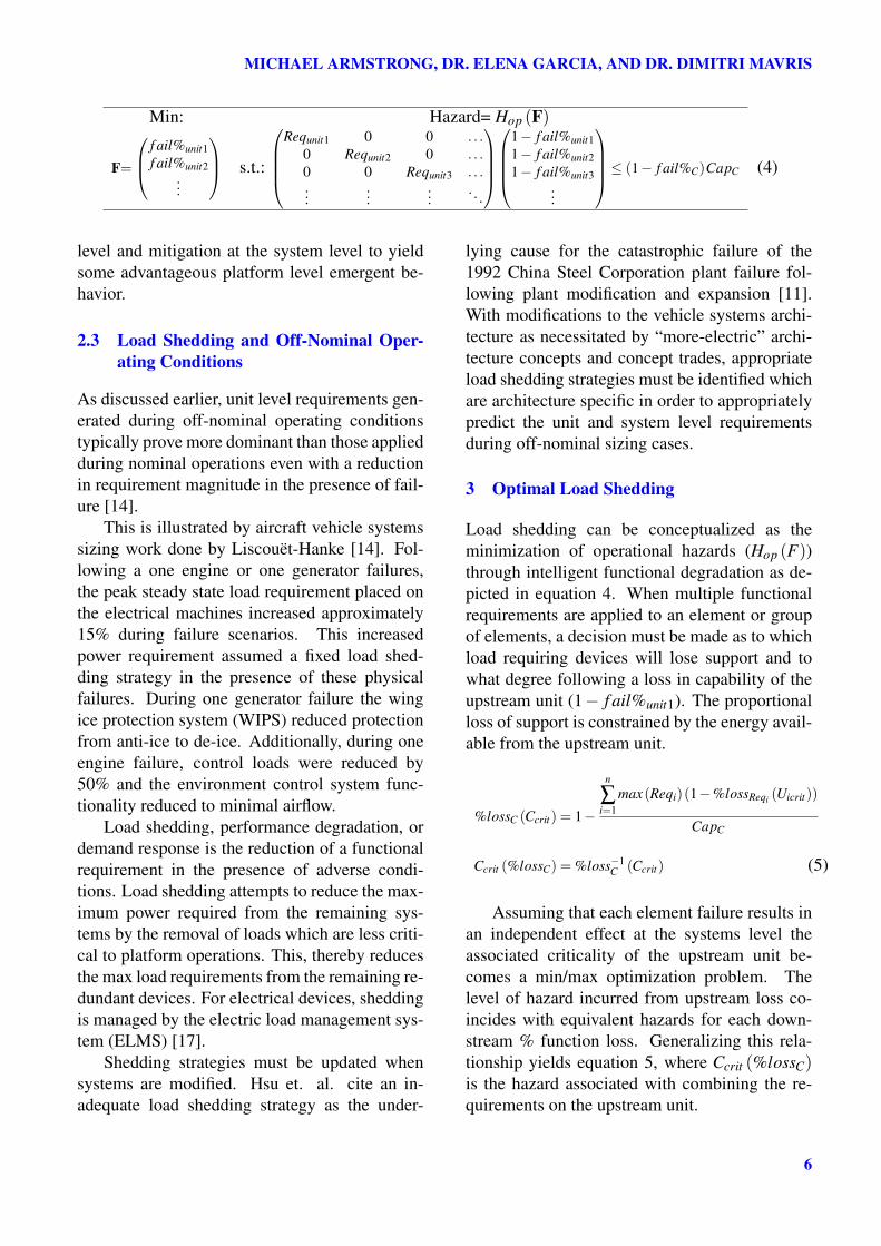
Load shedding can be conceptualized as theminimization of operational hazards (Hop (F))through intelligent functional degradation as de-picted in equation 4. When multiple functionalrequirements are applied to an element or groupof elements, a decision must be made as to whichload requiring devices will lose support and towhat degree following a loss in capability of theupstream unit (1− f ail%unit1). The proportionalloss of support is constrained by the energy avail-able from the upstream unit.
%lossC (Ccrit) = 1−
n
∑i=1
max(Reqi)(1−%lossReqi (Uicrit))
CapC
Ccrit (%lossC) = %loss−1C (Ccrit) (5)
Assuming that each element failure results inan independent effect at the systems level theassociated criticality of the upstream unit be-comes a min/max optimization problem. Thelevel of hazard incurred from upstream loss co-incides with equivalent hazards for each down-stream % function loss. Generalizing this rela-tionship yields equation 5, where Ccrit (%lossC)is the hazard associated with combining the re-quirements on the upstream unit.
6
Aircraft Mission and System Failure Considerations for Functional Induction Based ConceptualArchitecture Design
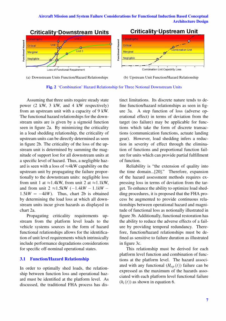
(a) Downstream Units Function/Hazard Relationships (b) Upstream Unit Function/Hazard Relationship
Fig. 2 ‘Combination’ Hazard Relationship for Three Notional Downstream Units
Assuming that three units require steady statepower (2 kW, 3 kW, and 4 kW respectively)from an upstream unit with a capacity of 9 kW.The functional hazard relationships for the down-stream units are is given by a sigmoid functionseen in figure 2a. By minimizing the criticalityin a load shedding relationship, the criticality ofupstream units can be directly determined as seenin figure 2b. The criticality of the loss of the up-stream unit is determined by summing the mag-nitude of support lost for all downstream units ata specific level of hazard. Thus, a negligible haz-ard is seen with a loss of ≈4kW capability on theupstream unit by propagating the failure propor-tionally to the downstream units: negligible lossfrom unit 1 at ≈1.4kW, from unit 2 at ≈1.1kW,and from unit 2 ≈1.5kW (−1.4kW − 1.1kW −1.5kW = −4kW ). Thus, chart 2b is obtainedby determining the load loss at which all down-stream units incur given hazards as displayed inchart 2a.
Propagating criticality requirements up-stream from the platform level loads to thevehicle systems sources in the form of hazardfunctional relationships allows for the identifica-tion of unit level requirements which intrinsicallyinclude performance degradations considerationsfor specific off-nominal operational states.
3.1 Function/Hazard Relationship
In order to optimally shed loads, the relation-ship between function loss and operational haz-ard must be identified at the platform level. Asdiscussed, the traditional FHA process has dis-
tinct limitations. Its discrete nature tends to de-fine function/hazard relationships as seen in fig-ure 3a. A step function of loss (adverse op-erational effect) in terms of deviation from thetarget (no failure) may be applicable for func-tions which take the form of discrete transac-tions (communication functions, actuate landinggear). However, load shedding infers a reduc-tion in severity of effect through the elimina-tion of functions and proportional function fail-ure for units which can provide partial fulfillmentof function.
Reliability is “the extension of quality intothe time domain...[20].” Therefore, expansionof the hazard assessment methods requires ex-pressing loss in terms of deviation from the tar-get. To enhance the ability to optimize load shed-ding procedures, it is proposed that the FHA pro-cess be augmented to provide continuous rela-tionships between operational hazard and magni-tude of functional loss as notionally illustrated infigure 3b. Additionally, functional restoration hasthe ability to reduce the adverse effects of a fail-ure by providing temporal redundancy. There-fore, function/hazard relationships must be de-fined as sensitive to failure duration as illustratedin figure 3c.
This relationship must be derived for eachplatform level function and combination of func-tions at the platform level. The hazard associ-ated with any functional (Hop (t)) failure can beexpressed as the maximum of the hazards asso-ciated with each platform level functional failure(hi (t)) as shown in equation 6.
7

MICHAEL ARMSTRONG, DR. ELENA GARCIA, AND DR. DIMITRI MAVRIS
(a) Functionally Discrete (b) Functionally Continuous
(c) Continuous in Function and Du-ration
Fig. 3 Function/Hazard Objective Function forLoad Shedding Optimization
Hop (t) = max [h1 (t) ,h2 (t) , · · · ,h1,2 (t) , · · · ] (6)
hi (t) = f (Fi,τ,alt (t) ,M (t) ,dist (t) , · · ·) (7)
Each individual functional hazard relation-ship (hi (t)) is a function of capability lost (Fi)and is scaled by the potential for recovery, as seenin equation 7. Recovery is expressed as a func-tion of the duration of the functional failure (τ)and mission conditions (altitude, Mach number,distance from potential landing field, hazardousenvironments, . . . ). These conditions are timevariant as the platform progresses throughout themission. The operational effect of a loss in thrustfor 30 seconds is much more hazardous duringlow altitude flight and takeoff than for higher al-titude operations. A proportional loss of thrustwhich still yields excess power may prove catas-trophic during obstacle clearance. However, aloss of thrust resulting in an inability to maintainsteady level flight might be less hazardous duringhigher altitude operations.
Assuming independent functional hazardsimplies that hi, j,··· = 0. Applying this assump-tion allows for a closed form solution of hazardin terms of upstream and downstream element at-tributes. However, in general, these relationships
Fig. 4 Restructured Reliability Block Diagramfor Proportional Load Sharing
may be developed through the optimization ex-pressed in equation 5.
Expressing the probability constraint in termsof % functional failure significantly alters themeans in which system reliability must be calcu-lated to verify that these continuous constraintsare met. Reliability must also be determined interms of probability of proprotional functionallosses. Based on traditional means, load sharingreliability is obtained through n-out-of-k relation-ships. In the case of proportional loading there isno assurance that a specific number of combinedelements will provide sufficient functionality. Inthis case, the reliability of providing a functionalrequirement depends on the capacity of each ele-ment or combination of elements. Restructuringthe reliability block diagram involves identifyingall potential combinations and applying logic re-garding the capability available from each paral-lel path as visualized in figure 4.
Assume three units with capacities of 3kW,5kW, and 6kW with reliabilities of 0.8, 0.9, and0.99 respectively. The maximum load sharing ca-pacity is 14kW with decreasing reliability withincreasing requirements. The reliability of thisgroup of elements with respect to the magnitudeof functional requirement is illustrated in figure5. For requirements under 3kW any of the avail-able systems may be used. Between 3 and 5kW,the units with 5 or 6kW devices must be operable.With requirements between 5 and 6kw, unit 3 canfulfill the requirements in isolation, or with thecombination of the 3 and 5kW devices. For re-
8

Aircraft Mission and System Failure Considerations for Functional Induction Based ConceptualArchitecture Design
Fig. 5 Degradation of Reliability with Vary-ing Magnitude of Functional Requirement for aThree Unit Load Sharing Group
quired capacities above 6kW, combinations of el-ements must be used to fulfill functional require-ments.
A breech in the reliability constraint can oc-cur at any magnitude of functional failure. Figure6 shows the notional three unit shared load reli-ability superimposed on a maximum probabilityallowed as defined through continuous FHA. Asseen in this figure, the system is less likely tofail in providing low levels of capability. How-ever, providing minimal power requirements isalso more stringently constrained. In this exam-ple insufficient reliability is achieved for highlycritical low power requirements while adequatereliability is provided for power requirements ex-ceeding ≈7kW. In this circumstance overratingindividual units proves insufficient to providingadequate reliability at low power requirements.Solutions in this case may include the introduc-tion of additional redundant systems, or increas-ing the reliability of one or more of the existingunits.
This approach to hazard identification and as-sessment allows the conceptual designer to deter-mine criticality associated with proportional unitfailures considering architecture specific optimalload shedding strategies. Additionally, when ar-chitectures prove insufficient in meeting reliabil-ity requirements, visually inspecting the relation-ship between the unit reliability and constraint inthis continuous fashion provides insight and mo-tivation towards providing solutions to reliabil-ity problems (redundancy, overrating, functional
Fig. 6 Load Sharing Reliability with CriticalityConstraint
restoration, increased unit reliability).
3.2 Criticality Propagation
Formulating load shedding optimization requiresa detailed understanding of how functional re-quirements flow throughout a system. Everypoint in the architecture where multiple unitspresent load requirements to a single unit orgroup of units necessitates the prioritization ofdownstream units. When generating concept ar-chitectures these points must be systematicallyidentified with sufficient information to formatfunction/hazard relationships for upstream sys-tems in terms of unique shedding strategies.
Function/hazard information must be madeavailable at all points in the architecturewhere these shedding decisions must be made.Additionally, all unit level continuous func-tional/reliability requirements must be traceableto the support of platform level functions and op-erations in light of optimal performance degrada-tion strategies.
Complex unit interactions and highly interde-pendent structures of aircraft vehicle systems ar-chitectures pose difficulty in the traditional hier-archical flow-down of functional and reliabilityrequirements. Therefore, a systematic means forthe management of architecture relationships inthe communication of requirements is necessary.This is achieved through Functional Induction.
Functional dependency relationships commu-nicate requirements from the platform to each in-dividual unit or groups of units. Functional in-duction is used to manage the implementation
9

MICHAEL ARMSTRONG, DR. ELENA GARCIA, AND DR. DIMITRI MAVRIS
space of concept definition by requiring the spec-ification of all dependent relationships betweenelements [16]. Definition of architecture imple-mentation follows function definition. The firstset of functions is provided from the operationaldescription of the platform. These architec-ture independent functions are termed boundaryfunctions. Subsequent functions are introducedfollowing architecture implementation definition.Each decision introduces additional functionswhich must be fulfilled. Internal system func-tional relationships are termed induced functions.Redundant units providing the same functionalityare termed functional groups. Defining the sys-tem through the assignment of unit dependenciesprovides the structure for propagating criticalitythroughout the architecture.
The result of system definition followingfunctional induction is a directed graph rep-resenting the communication of requirementsthrough functional relationships. These directedgraphs use edges to communicate requirements(load, hazard) upstream and capability (reliabil-ity) downstream between nodes. Three specifictypes of node elements are used to propagatefunction hazard relationships: combination, allo-cation, and simple. A combination element is in-stantiated when multiple loads feed into a sourceelement. An allocation element is instantiatedwhen multiple source units can provide for re-quirements communicated by a single edge load(these sources form a functional group). Simpleelement represents a single unit providing a loadto be fulfilled by another single unit. These threerelationships are graphically displayed in table 1.In this table the yellow circle represents a unit,the dashed blue circle represents some undefinedupstream unit or group of units, and the dashedbox represents a functional group (group of ele-ments providing the same functionality).
Ucriti (%lossi) = Acrit((%lossi− ki)
CapUi
max(ReqA)
)(8)
ki =
(n
∑j=1
CapU j
)−max(ReqA)
CapUi
Table 1 Convention for Unit Requirements Rela-tionships Relationship Types
Type Diagram
Simple
Allocation
Combination
The combination relationship was introducedbefore with equation 4 and generalized for in-dependent function/hazard relationships in equa-tion 5. The allocation/load-sharing relation-ship is given in equation 8. In this expressionUcriti (%lossi) is the hazard failure relationship,Acrit(%lossA) is the hazard function of the allo-cation element, CapUi is the capacity of unit i, nis the number of upstream units, and max(ReqA)is the maximum requirement generated from thedownstream element through the allocation ele-ment. The general equation propagating critical-ity requirements upstream through a simple rela-tionship is the same as for an allocation elementswith one upstream unit (equation 8, n = 1).
Equations 5 and 8 act to propagate the func-tion/hazard relationship through all unit func-tional interdependencies. Assuming that up-stream element failures of a given duration im-pose a loss of function support of all downstreamunits for the same duration, these equations fol-low the same form but capture sensitivity to lossduration: Ucriti (%lossi,τ) and Ccrit (%losses,τ).
Systematically identifying the criticality re-quirements for individual units by consider-ing graphical interactions enhances the archi-tects ability to identify architecture specific op-erational requirements concurrent to architec-
10

Aircraft Mission and System Failure Considerations for Functional Induction Based ConceptualArchitecture Design
Fig. 7 Combination-Allocation Relationship forNotional System Providing Electrical Power
ture definition. This graph propagates func-tion/hazard relationships throughout to all systemelements by way of combination and allocationrelationships. Each function/hazard curve acts toconstrain the physical and behavioral attributes ofthe units according to the criticality of the func-tionality it provides. Once these relationships arein place, the variation in load and criticality re-quirements during a mission may be determinedas the boundary level function/hazard relation-ship varies in time. Extending these relationshipsinto the fault duration domain will also enhancethe ability of the vehicle systems designer to visu-ally inspect the benefits to temporal or spatial re-dundancy solutions, when reliability constraintsare breeched.
3.3 Complex Allocation-Combination Rela-tionships
As discussed in the previous sections, redundant,load-sharing relationships reduce the necessity toprovide capability and reliability with a singleunit. However, with complex graphs, subsequentupstream relationships may necessitate that infor-mation be made available from all downstreamfunctional dependencies. These relationships areaffected by the complexity of the system graph.
Consider the notional example displayed infigure 7. The hazard associated with the upstreamUnit 9 (Fuel System) must be expressed as thecombination of multiple downstream elements allsupporting a similar allocation element. With to-tal loss of U9, R1 (provide electrical power) can-not be fulfilled. Therefore, the U9 failure/hazardcurve cannot be calculated directly as a function
of the adjacent unit criticality. Structural infor-mation must propagate upstream all the way fromthe boundary requirement.
Requirements and criticality communicatedthrough each of the edges in this directed graphmust carry information regarding requirementorigin and augmentation. Edge tags for the fig-ure above are displayed in table 2. In this table,the allocation relationship is indicated by triangu-lar brackets: e.g.
⟨Ui
U1,U2,···
⟩. Combinations are
displayed with comma separated and parenthe-sized elements or allocations. Edges which stemfrom units in an allocation relationship are taggedby the proportion of the downstream requirement(in this case R1) provided by the unit. In orderto fully characterize the sources of criticality forupstream units, criticality elements sum the re-quirements being received from downstream.
Table 2 Information Communicated with GraphEdges from Figure 7
Edge Requirement Proportion
1 R1
2 1η1
R1
⟨U1
U1,U2
⟩3 1
η1η3R1
⟨U1
U1,U2
⟩⟨U3
U3,U4
⟩4 1
η1η4R1
⟨U1
U1,U2
⟩⟨U4
U3,U4
⟩5 1
η1R1
⟨U1
U1,U2
⟩|(
1η3
⟨U3
U3,U4
⟩, 1
η4
⟨U4
U3,U4
⟩)6 1
η2R1
⟨U2
U1,U2
⟩7 1
η2η5R1
⟨U2
U1,U2
⟩⟨U5
U5,U6
⟩8 1
η2η6R1
⟨U2
U1,U2
⟩⟨U6
U5,U6
⟩9 1
η2R1
⟨U2
U1,U2
⟩|(
1η5
⟨U5
U5,U6
⟩, 1
η6
⟨U6
U5,U6
⟩)10 R1|
1η1η3η7
⟨U1
U1,U2
⟩⟨U3
U3,U4
⟩, 1
η1η4η7
⟨U1
U1,U2
⟩⟨U4
U3,U4
⟩,
1η2η5η8
⟨U2
U1,U2
⟩⟨U5
U5,U6
⟩, 1
η2η6η8
⟨U2
U1,U2
⟩⟨U6
U5,U6
⟩
For allocation-combination graphs efficiencyinformation must be taken into account whileconsidering optimal load shedding. Assum-ing paths are shed in order of efficiency (leastefficient to most efficient) the slope of thefunction/hazard relationship will sequentially in-crease as the shed parallel paths increase in effi-ciency. Graph tags, therefore, include informa-tion regarding the efficiency of the paths. Theparenthesized groupings of elements seen in ta-ble 2 indicate that the associated criticality curve
11
MICHAEL ARMSTRONG, DR. ELENA GARCIA, AND DR. DIMITRI MAVRIS
(R1 in the case of edge 10) must be reformed withregards to the capability and efficiencies of theparallel unit paths.
Looking at combination elements in this ex-ample, the criticalities of engines U7 and U8 arederived through an efficiency scaled simple rela-tionship with the buses U1 and U2 respectively.Additionally, the criticality of the fuel system(U9) receiving edge 10 can be expressed as anefficiency adjusted simple relationship with theoriginal boundary requirement to provide powerR1. With total loss at U9 the requirement, R1,cannot be fulfilled.
Decomposing and propagating unit critical-ity in this fashion imposes reliability constraintswhich limit the capacity and reliability of eachunit depending on its specific functional depen-dencies. These reliability constraints are definedwith respect to architecture specific load shed-ding strategies generated by hazard minimiza-tion for every combination relationship whichconsider the support of the ultimate downstreamfunctionality.
3.4 Staggered Combinations and Allocations
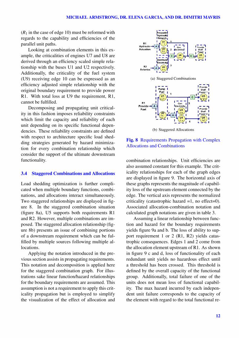
Load shedding optimization is further compli-cated when multiple boundary functions, combi-nations, and allocations interact simultaneously.Two staggered relationships are displayed in fig-ure 8. In the staggered combination situation(figure 8a), U5 supports both requirements R1and R2. However, multiple combinations are im-posed. The staggered allocation relationship (fig-ure 8b) presents an issue of combining portionsof a downstream requirement which can be ful-filled by multiple sources following multiple al-locations.
Applying the notation introduced in the pre-vious section assists in propagating requirements.This notation and decomposition is applied herefor the staggered combination graph. For illus-trations sake linear function/hazard relationshipsfor the boundary requirements are assumed. Thisassumption is not a requirement to apply this crit-icality propagation but is employed to simplifythe visualization of the effect of allocation and
(a) Staggered Combinations
(b) Staggered Allocations
Fig. 8 Requirements Propagation with ComplexAllocations and Combinations
combination relationships. Unit efficiencies arealso assumed constant for this example. The crit-icality relationships for each of the graph edgesare displayed in figure 9. The horizontal axis ofthese graphs represents the magnitude of capabil-ity loss of the upstream element connected by theedge. The vertical axis represents the normalizedcriticality (catastrophic hazard =1, no effect=0).Associated allocation-combination notation andcalculated graph notations are given in table 3.
Assuming a linear relationship between func-tion and hazard for the boundary requirementsyields figure 9a and b. The loss of ability to sup-port requirement 1 or 2 (R1, R2) yields catas-trophic consequences. Edges 1 and 2 come fromthe allocation element upstream of R1. As shownin figure 9 c and d, loss of functionality of eachredundant unit yields no hazardous effect untila threshold has been crossed. This threshold isdefined by the overall capacity of the functionalgroup. Additionally, total failure of one of theunits does not mean loss of functional capabil-ity. The max hazard incurred by each indepen-dent unit failure corresponds to the capacity ofthe element with regard to the total functional re-
12

Aircraft Mission and System Failure Considerations for Functional Induction Based ConceptualArchitecture Design
(a) Edge R1 (b) Edge R2 (c) Edge 1 (d) Edge 2
(e) Edge 3 (f) Edge 4 (g) Edge 5
Fig. 9 Function/Hazard Relationships for Edges of the Staggered Combination Graph Depicted in Figure 8a.
quirements.Edge 3 maintains a linear relationship with
a catastrophic failure for 100% loss of the up-stream unit. However, this criticality is offset bythe overrating of U3 and scaled by U3 efficiency.
Calculating the criticality of requirementscommunicated through edge 4 begins to addressoptimal load shedding. No hazard is seen withfailures of units upstream of U4 until all over-rated capability has been lost from U2, U3, andU4. The first linear increase in hazard occurswith with simultaneous failure through U2 andU3 until the max hazard for U2 loss has be seen.The steeper linear section occurs once U2 has lostall functional support and R1 has lost all possi-ble capability through U4 failure. Therefore, thissecond section represents loss to R1.
Edge 5 has 4 linear sections. The first is aconstant offset which includes the overrating as-sociated with the path R2-U3-U4 and the maxi-mum available overrating from R1-U1 or R1-U2-U4. The second section includes load sheddingfor the least efficient path from U1 to U5 and thepath from U2 to U5. Once load has been shedfrom the least efficient path, the third section rep-resents proportional losses through the more effi-cient path.
Characterizing the system in terms of a di-rected graph through functional induction rela-tionships between elements allows criticality re-lationships to be propagated throughout a com-
Table 3 Propagation of Function/Hazard Rela-tionship for the Edges in Figure 8a.
Equations
9c.
Notation :1
η1R1
⟨U1
U1,U2
⟩X1 =U1max +U2max −R1maxH1 = HR1 (U1max )
9d.
Notation :1
η2R1
⟨U2
U1,U2
⟩X2 =U1max +U2max −R1maxH2 = HR1 (U2max )
9e.Notation :
1η3
R1
X3 =U3max −R2max
9f.
Notation :1
η4
(1
η2R1
⟨U2
U1,U2
⟩,
1η3
R2
)
X41 =U4max −1
η2(U2max −X2)−
1η3
(U3max −X3)
X42 =1
η2U2max −
1η2
X2
X43 =1
η3R3max −
[R3 (H2)− 1
η3X3
]
9g.
Notation :1
η4
(1
η1R1
⟨U1
U1,U2
⟩,
1η2
R1
⟨U2
U1,U2
⟩,
1η3
R2
)
X51 = max(
1η1
,1
η2η3
)X1 +
1η3η4
X3
X52 =
1
η1≤ 1
η2η4:
1η1
U1max −1
η1X1 +R3 (H1)
o.w. :1
η2η4U2max −
1η2η4
X1 +R3 (H2)
X53 =
1
η1≤ 1
η2η4:
1η2η4
U2max −1
η2η4X2 +[R3 (H1 +H2)−R3 (H1)]
o.w. :1
η1U1max −
1η1
X1 +[R3 (H1 +H2)−R3 (H2)]
H5 =
1
η1≤ 1
η2η4: H1
o.w. : H2
First column in reference to the graph displayed in figure 9
13

MICHAEL ARMSTRONG, DR. ELENA GARCIA, AND DR. DIMITRI MAVRIS
plex system through unit interdependencies. Sup-plying information regarding downstream graph-ical relationships to the upstream load providersallows complicated relationships to be reducedin terms of their impact on the ultimate pro-vision of some capability demand expressed atthe platform level. Propagating this informationthroughout the system is necessary in order to op-timize load shedding for each combination rela-tionship.
While calculations for this example do notextend into the time domain, these graphs canrepresent the projection of the hazard curve fora given failure duration (τ).
Additionally, with more complex unit re-quirement propagation (i.e. a requirement crit-icality coming out of a unit has a nonlinear re-lationship with incoming requirement criticality)downstream %loss must be expressed as a func-tion of upstream %loss. Therefore, to fully char-acterize this continuous relationship future workwill explore the use of surrogate models in defin-ing the efficiencies as a function of magnitude ofrequirements and other environment conditions.
4 Conclusion
Reconsidering the system optimization in equa-tion 1, performance degradation considerationseffect the architecture design by manipulation ofthe design constraints. Probability constraintsat the unit level must consider off-nominal op-erating modes unique to each architecture con-cept. Requirements emerge in the form of siz-ing critical off-nominal load shedding strategieswhich must be optimized to minimize probabilityof hazard. Additionally, failure conditions poseunique energy requirements to architecture unitsduring architecture sizing. As concept trades areperformed, these emergent requirements must beidentified and applied to justify architecture se-lection.
Designers must identify the relationship be-tween operational hazards and the magnitude offunctional requirements in the context of the plat-form mission. The application of fixed reliabil-ity constraints generated by FHA’s traditional as-
sumptions regarding failure states is remedied inthis work by expressing hazards as a continu-ous relationship with the magnitude and durationof functional failure and other mission parame-ters. Continuous functional hazard relationshipsprovide the objective function for the definitionof requirements in terms of architecture specificperformance degradation strategies. While tradi-tional conceptual design methods make assump-tions regarding the shedding of loads for vehiclesystem sizing, requirements are generated herewhich intrinsically involve optimal performancedegradation through load shedding optimization.
In order to define optimal load sheddingstrategies, these continuous reliability/capacityconstraints must be communicated to all pointsin the system where load shedding is feasi-ble. Functional Induction is utilized for archi-tecture specification (graph definition). Meanswere introduced which catalog complex rela-tionships between the boundary and unit re-quirements and track requirements through func-tional interdependencies. Combination and al-location elements were introduced to managegraph complexity and logically determine opti-mal load shedding. Thus, the systematic identifi-cation of optimal shedding strategies is achievedthrough propagating function/hazard relation-ships throughout a system following functionaldependencies and then generating upstream re-quirements through the minimization of hazardsat all combination relationships.
With the basic framework in place, futurework includes the automation of function/hazardrelationship generation during graph construc-tion. These relationships must be updated toincluded additional dimensions; fault durationand mission conditions. Assumptions regardingunit efficiency and the independence of platformfunction hazards will also be addressed.
Systematic definition of off-nominal require-ments is necessary to accurately predict unit andplatform level attributes. The tools and meth-ods discussed in this paper represent initial stepsin the identification and propagation of emergentoff-nominal sizing requirements during the con-cept development of complex vehicle systems.
14

Aircraft Mission and System Failure Considerations for Functional Induction Based ConceptualArchitecture Design
5 Copyright Statement
The authors confirm that they, and/or their company ororganization, hold copyright on all of the original ma-terial included in this paper. The authors also confirmthat they have obtained permission, from the copy-right holder of any third party material included in thispaper, to publish it as part of their paper. The authorsconfirm that they give permission, or have obtainedpermission from the copyright holder of this paper, forthe publication and distribution of this paper as part ofthe ICAS2010 proceedings or as individual off-printsfrom the proceedings.
References
[1] K. Allenby and T. Kelly. Deriving safety re-quirements using scenarios. Rolls-Royce PLC-Report-PNR, 2001.
[2] J.L. Casti. On system complexity: Identifi-cation, measurement and management. Com-plexity, Language and Life: Mathematical Ap-proaches, 16:146–173, 1986.
[3] Michael A. Dornheim. Boeing 787 technology:Massive 787 electrical system pressurizes cabin.Aviation Week and Space Technology, 2005.
[4] Lester Faleiro. Power optimized aircraft tochange industry mindset. Interavia Businessand Technology, 2002.
[5] Federal Aviation Administration. Advisory Cir-cular 25.1309-1A, 1988.
[6] P. Fenelon, JA McDermid, M. Nicolson, andDJ Pumfrey. Towards integrated safety analysisand design. ACM SIGAPP Applied ComputingReview, 2(1):21–32, 1994.
[7] G. Flake. Review of the computational beautyof nature. AI Magazine, 21(2), 2000.
[8] S. Funtowicz and J.R. Ravetz. Emergent com-plex systems. Futures, 26(6):568–582, 1994.
[9] D. Harel and A. Pneuli. On the development ofreactive systems. Logics and Models of Concur-rent Systems, pages 477 – 498, 1985.
[10] D.C. Hays. Requirements analysis: from busi-ness views to architecture. Prentice Hall, 2003.
[11] CT Hsu, CS Chen, and JK Chen. The load-shedding scheme design for an integrated steel-making cogeneration facility. IEEE Transac-
tions on Industry Applications, 33(3):586–592,1997.
[12] I. Jacobson. The use-case construct in object-oriented software engineering. Scenario-baseddesign: envisioning work and technology in sys-tem development, pages 309–336, 1995.
[13] J. Lin, M.S. Fox, and T. Bilgic. A requirementontology for engineering design. ConcurrentEngineering, 4(3):279, 1996.
[14] Susan Liscouët-Hanke. A Model-BasedMethodology for Integrated Preliminary Sizingand Analysis of Aircraft Power System Architec-tures. PhD thesis, Université de Toulouse, 2008.
[15] U. Lösch, J. Dugdale, and Y. Demazeau. Re-quirements for supporting individual humancreativity in the design domain. EntertainmentComputing–ICEC 2009, pages 210–215.
[16] D. Mavris, C. de Tenorio, and M. Armstrong.Methodology for aircraft system architecturedefinition. In 46th AIAA Aerospace SciencesMeeting and Exhibit. AIAA, 2008.
[17] I. Moir and A.G. Seabridge. Aircraft systems:Mecanical, Electrical, and Avionics SubsystemsIntegration. AIAA, 2008.
[18] C. Rolland, C. Ben Achour, C. Cauvet, J. Ra-lyté, A. Sutcliffe, N. Maiden, M. Jarke,P. Haumer, K. Pohl, E. Dubois, et al. A pro-posal for a scenario classification framework.Requirements Engineering, 3(1):23–47, 1998.
[19] Schön, D.A. Educating the reflective practi-tioner. Jossey-Bass San Francisco, 1987.
[20] D.J. Smith. Reliability, maintainability and risk:practical methods for engineers. Butterworth-Heinemann, 2005.
[21] Vincent P. Socci. System design considera-tions for vehicle-based mobile electric powerapplications. In Power Electronic Technology2005/Session PET06, 2005.
[22] Society of Automotive Engineers. ARP4754: Certification considerations for highly-integrated or complex aircraft systems, 1996.
[23] J. Talbot and M. Jakeman. Security risk man-agement body of knowledge. Wiley, 2009.
[24] I-Ling Yen, Raymond Paul, and Kinji Mori.Toward integrated methods for high-assurancesystems. Computer, 31(4):34, 1998.
15