aircraft noise reduction : airbus industrial needs in ... · presented by: hervé batard aircraft...
TRANSCRIPT

Presented by: Hervé Batard
Aircraft noise reduction : AIRBUS industrial needs in terms of new materials for nacelle liners
Journées scientifiques de l’ONERA - January 16th, 2003
January 2003
January 2003 Page 2© A
IRBU
S S.
A.S.
All
right
s re
serv
ed. C
onfid
entia
l and
pro
prie
tary
doc
umen
t.
EEA
Summary
• Noise & aircraft design
• Propulsion noise reduction�Low noise configurations and flight procedures�Engine source�Nacelle geometry and liners
• Liner impedance requirements
• Conclusion

January 2003 Page 3© A
IRBU
S S.
A.S.
All
right
s re
serv
ed. C
onfid
entia
l and
pro
prie
tary
doc
umen
t.
EEA
Aircraft noise: A complex mix of different sources
Take-off
Com
bust
or
Jet
Engi
ne T
otal
Airc
raft
Tota
l
Airfr
ame
Turb
ine
Com
pres
sor
Fan5 dB
Approach
Com
bust
or
Jet
Engi
ne T
otal
Airc
raft
Tota
l
Airfr
ame
Turb
ine
Com
pres
sor
Fan
5 dB
• Take-off: Jet & Fan
• Approach: Fan & airframe
FAN ANDCOMPRESSOR NOISE
AIRFRAME NOISEFAN, TURBINE ANDCOMBUSTOR NOISE
JET MIXING NOISE
January 2003 Page 4© A
IRBU
S S.
A.S.
All
right
s re
serv
ed. C
onfid
entia
l and
pro
prie
tary
doc
umen
t.
EEA
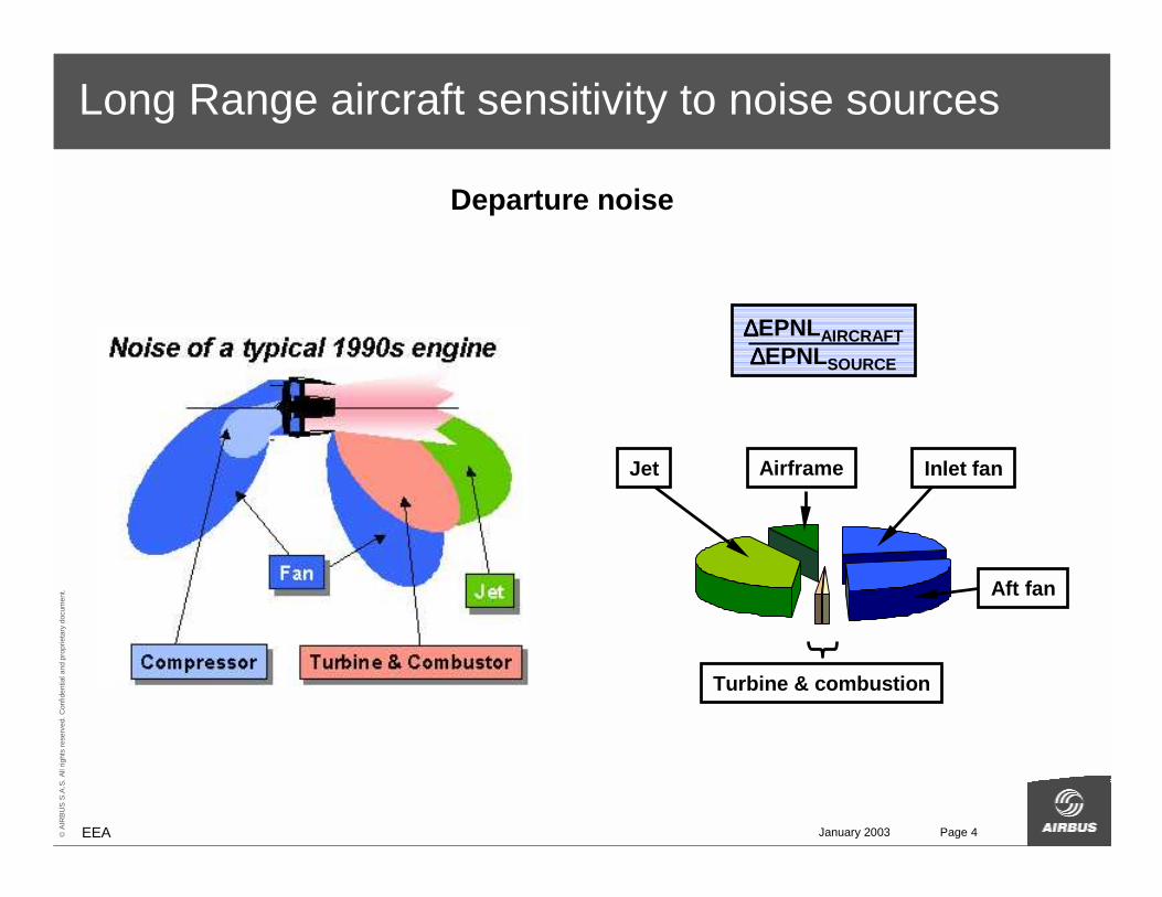
Long Range aircraft sensitivity to noise sources
Jet Airframe Inlet fan
Aft fan
Turbine & combustion
∆∆∆∆EPNLAIRCRAFT∆∆∆∆EPNLSOURCE
Departure noise
January 2003 Page 5© A
IRBU
S S.
A.S.
All
right
s re
serv
ed. C
onfid
entia
l and
pro
prie
tary
doc
umen
t.
EEA
© Airbus 2002 Computer Graphics by I3M
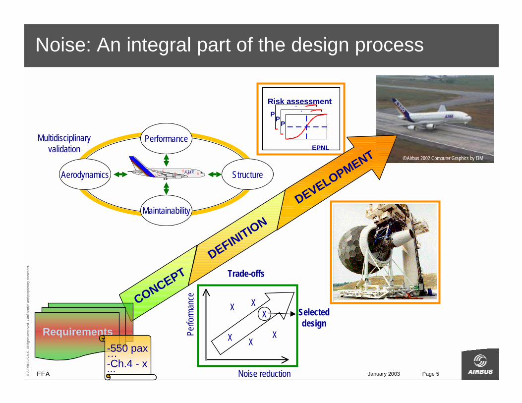
Noise: An integral part of the design process
CONCEPT
Requirements-550 pax…-Ch.4 - x...
DEFINITION
A3XX Structure
Performance
Maintainability
Aerodynamics
Multidisciplinaryvalidation
EPNL
P
Risk assessment
P
EPNL
P
DEVELOPMENT
Noise reduction
Selected design
Perfo
rman
ce
X X
XX
X
X
Trade-offs
January 2003 Page 6© A
IRBU
S S.
A.S.
All
right
s re
serv
ed. C
onfid
entia
l and
pro
prie
tary
doc
umen
t.
EEA
� Airbus 2002 Computer Graphics by I3M
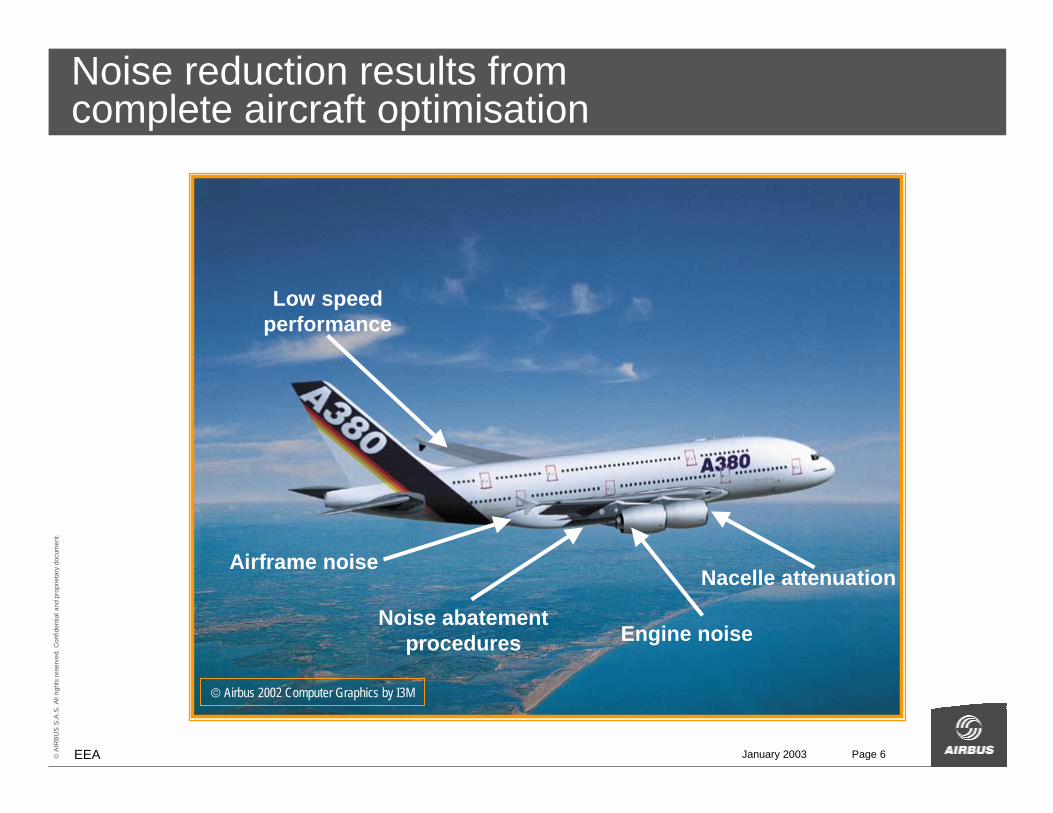
Noise reduction results fromcomplete aircraft optimisation
Nacelle attenuation
Engine noise
Airframe noise
Low speedperformance
Noise abatement procedures
January 2003 Page 7© A
IRBU
S S.
A.S.
All
right
s re
serv
ed. C
onfid
entia
l and
pro
prie
tary
doc
umen
t.
EEA
Summary
• Noise & aircraft design
• Propulsion noise reduction�Low noise configurations and flight procedures�Engine source�Nacelle geometry and liners
• Liner impedance requirements
• Conclusion
January 2003 Page 8© A
IRBU
S S.
A.S.
All
right
s re
serv
ed. C
onfid
entia
l and
pro
prie
tary
doc
umen
t.
EEA
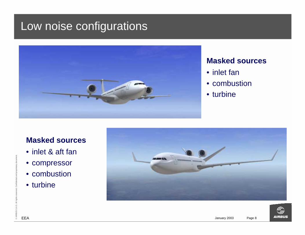
Low noise configurations
Masked sources• inlet fan• combustion• turbine
Masked sources• inlet & aft fan• compressor• combustion• turbine
January 2003 Page 9© A
IRBU
S S.
A.S.
All
right
s re
serv
ed. C
onfid
entia
l and
pro
prie
tary
doc
umen
t.
EEA
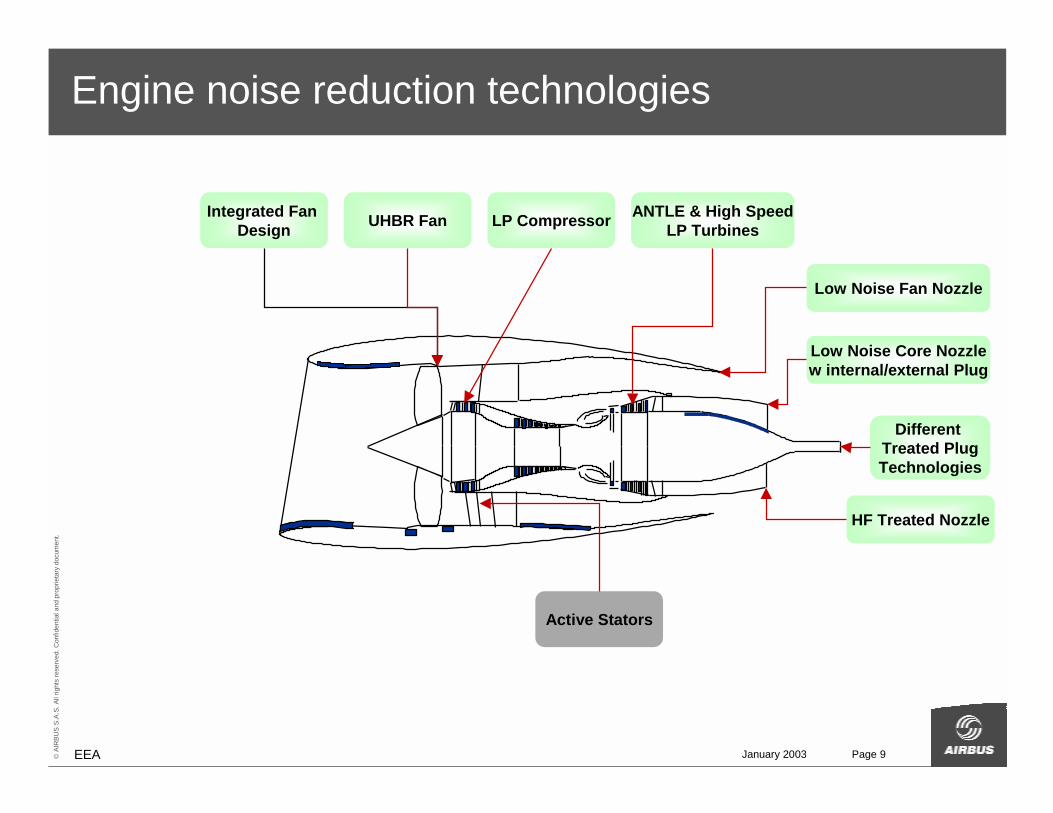
Engine noise reduction technologies
Active Stators
ANTLE & High Speed LP Turbines
Integrated Fan Design UHBR Fan LP Compressor
Low Noise Fan Nozzle
Low Noise Core Nozzlew internal/external Plug
Different Treated PlugTechnologies
HF Treated Nozzle
January 2003 Page 10© A
IRBU
S S.
A.S.
All
right
s re
serv
ed. C
onfid
entia
l and
pro
prie
tary
doc
umen
t.
EEA
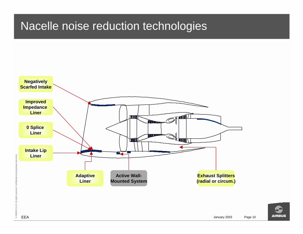
Nacelle noise reduction technologies
Active Wall-Mounted System
Intake LipLiner
Exhaust Splitters(radial or circum.)
AdaptiveLiner
NegativelyScarfed Intake
ImprovedImpedance
Liner
0 Splice Liner
January 2003 Page 11© A
IRBU
S S.
A.S.
All
right
s re
serv
ed. C
onfid
entia
l and
pro
prie
tary
doc
umen
t.
EEA
Summary
• Noise & aircraft design
• Propulsion noise reduction�Low noise configurations and flight procedures�Engine source�Nacelle geometry and liners
• Liner impedance requirements
• Conclusion
January 2003 Page 12© A
IRBU
S S.
A.S.
All
right
s re
serv
ed. C
onfid
entia
l and
pro
prie
tary
doc
umen
t.
EEA
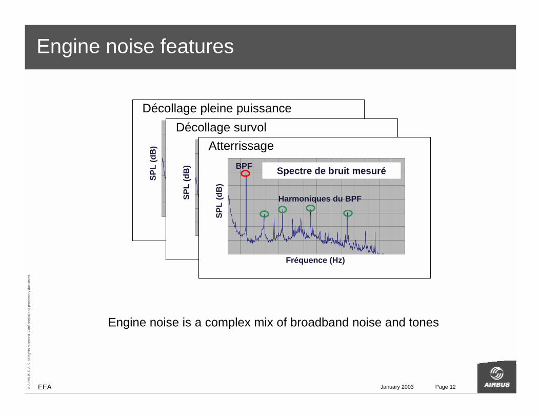
Engine noise features
Engine noise is a complex mix of broadband noise and tones
Spectre de bruit moteur à 2500rpm
70
75
80
85
90
95
100
105
0 1000 2000 3000 4000 5000 6000 7000 8000 9000 10000 11000 12000 13000 14000Freq (Hz)
dB SPL
Fréquence (Hz)
BPF
Harmoniques du BPFSP
L (d
B)
Spectre de bruit mesuré
Décollage pleine puissance Spectre de bruit moteur à 2500rpm
70
75
80
85
90
95
100
105
0 1000 2000 3000 4000 5000 6000 7000 8000 9000 10000 11000 12000 13000 14000Freq (Hz)
dB SPL
Fréquence (Hz)
BPF
Harmoniques du BPFSP
L (d
B)
Spectre de bruit mesuré
Décollage survolSpectre de bruit moteur à 2500rpm
70
75
80
85
90
95
100
105
0 1000 2000 3000 4000 5000 6000 7000 8000 9000 10000 11000 12000 13000 14000Freq (Hz)
dB SPL
Fréquence (Hz)
BPF
Harmoniques du BPF
SPL
(dB
)
Spectre de bruit mesuré
Atterrissage
January 2003 Page 13© A
IRBU
S S.
A.S.
All
right
s re
serv
ed. C
onfid
entia
l and
pro
prie
tary
doc
umen
t.
EEA
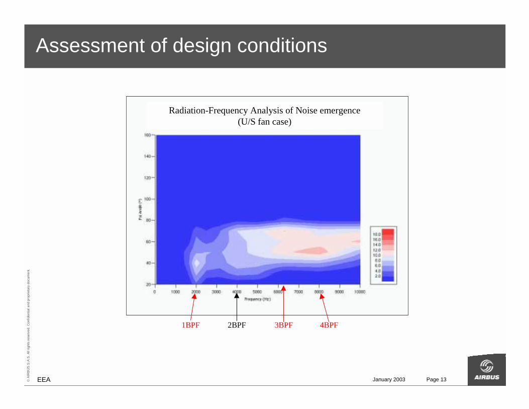
Assessment of design conditions
1BPF 2BPF 3BPF 4BPF
Radiation-Frequency Analysis of Noise emergence(U/S fan case)
January 2003 Page 14© A
IRBU
S S.
A.S.
All
right
s re
serv
ed. C
onfid
entia
l and
pro
prie
tary
doc
umen
t.
EEA
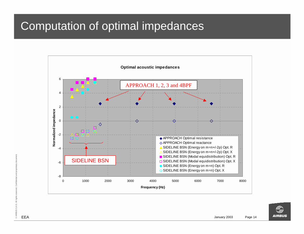
Computation of optimal impedances
Optimal acoustic impedances
-8
-6
-4
-2
0
2
4
6
0 1000 2000 3000 4000 5000 6000 7000 8000
Frequency (Hz)
Nor
mal
ized
impe
danc
e
APPROACH Optimal resistanceAPPROACH Optimal reactanceSIDELINE BSN (Energy on m=n+/-2p) Opt. RSIDELINE BSN (Energy on m=n+/-2p) Opt. XSIDELINE BSN (Modal equidistribution) Opt. RSIDELINE BSN (Modal equidistribution) Opt. XSIDELINE BSN (Energy on m=n) Opt. RSIDELINE BSN (Energy on m=n) Opt. X
APPROACH 1, 2, 3 and 4BPF
SIDELINE BSN
January 2003 Page 15© A
IRBU
S S.
A.S.
All
right
s re
serv
ed. C
onfid
entia
l and
pro
prie
tary
doc
umen
t.
EEA
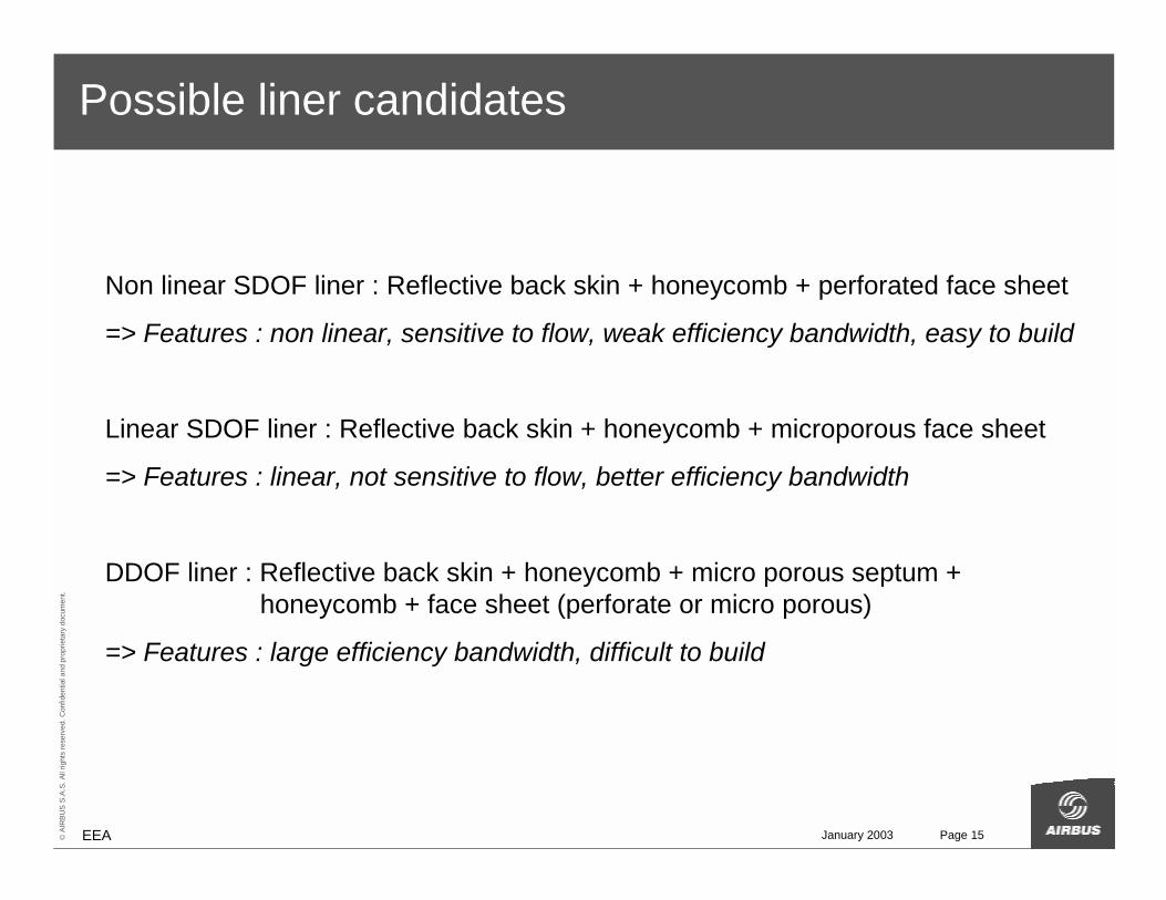
Possible liner candidates
Non linear SDOF liner : Reflective back skin + honeycomb + perforated face sheet
=> Features : non linear, sensitive to flow, weak efficiency bandwidth, easy to build
Linear SDOF liner : Reflective back skin + honeycomb + microporous face sheet
=> Features : linear, not sensitive to flow, better efficiency bandwidth
DDOF liner : Reflective back skin + honeycomb + micro porous septum + honeycomb + face sheet (perforate or micro porous)
=> Features : large efficiency bandwidth, difficult to build
January 2003 Page 16© A
IRBU
S S.
A.S.
All
right
s re
serv
ed. C
onfid
entia
l and
pro
prie
tary
doc
umen
t.
EEA
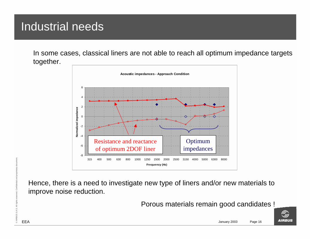
Industrial needs
In some cases, classical liners are not able to reach all optimum impedance targets together.
Acoustic impedances - Approach Condition
-8
-6
-4
-2
0
2
4
6
315 400 500 630 800 1000 1250 1500 2000 2500 3150 4000 5000 6300 8000
Frequency (Hz)
Norm
aliz
ed im
peda
nce
Hence, there is a need to investigate new type of liners and/or new materials to improve noise reduction.
Porous materials remain good candidates !
Optimumimpedances
Resistance and reactanceof optimum 2DOF liner
January 2003 Page 17© A
IRBU
S S.
A.S.
All
right
s re
serv
ed. C
onfid
entia
l and
pro
prie
tary
doc
umen
t.
EEA
Summary
• Noise & aircraft design
• Propulsion noise reduction�Low noise configurations and flight procedures�Engine source�Nacelle geometry and liners
• Liner impedance requirements
• Conclusion
January 2003 Page 18© A
IRBU
S S.
A.S.
All
right
s re
serv
ed. C
onfid
entia
l and
pro
prie
tary
doc
umen
t.
EEA
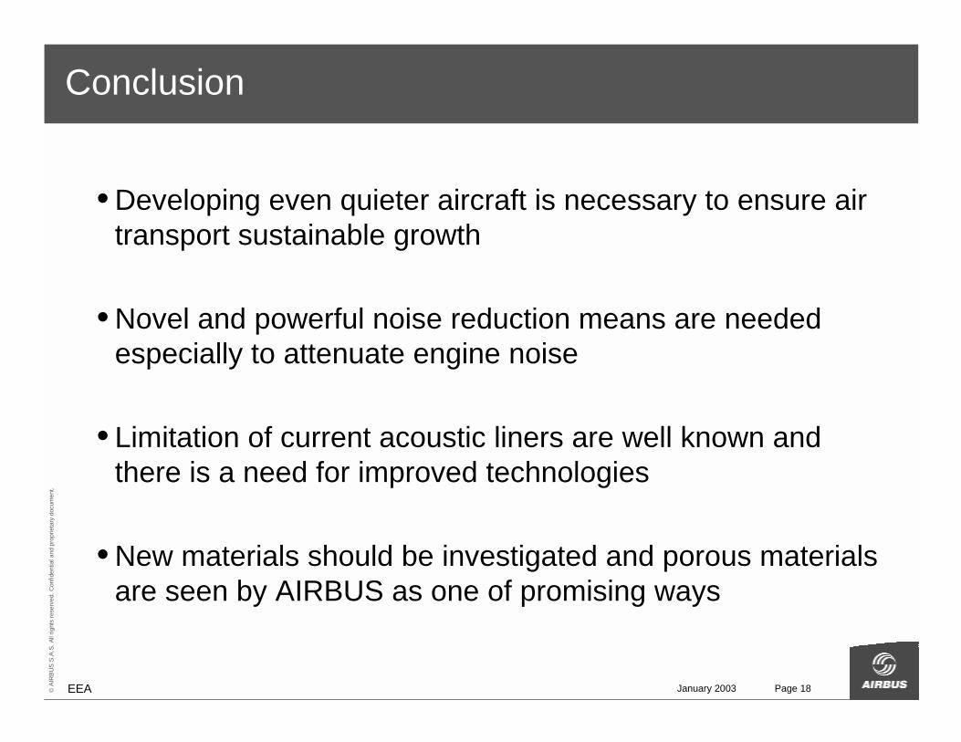
Conclusion
• Developing even quieter aircraft is necessary to ensure air transport sustainable growth
• Novel and powerful noise reduction means are needed especially to attenuate engine noise
• Limitation of current acoustic liners are well known and there is a need for improved technologies
• New materials should be investigated and porous materials are seen by AIRBUS as one of promising ways
January 2003 Page 19© A
IRBU
S S.
A.S.
All
right
s re
serv
ed. C
onfid
entia
l and
pro
prie
tary
doc
umen
t.
EEA
This document and all information contained herein is the sole property of AIRBUS S.A.S. No intellectual property rights are granted by the delivery of this document or the disclosure of its content. This document shall not be reproduced or disclosed to a third party without the express written consent of AIRBUS S.A.S. This document and its content shall not be used for any purpose other than that for which it is supplied.
The statements made herein do not constitute an offer. They are based on the mentioned assumptions and are expressed in good faith. Where the supporting grounds for these statements are not shown, AIRBUS S.A.S. will be pleased to explain the basis thereof.
AN EADS JOINT COMPANYWITH BAE SYSTEMS