aircraft stability
DESCRIPTION
Aircraft stability and control. TheoryTRANSCRIPT

VOLUME II FLYING QUALITIES PHASE
CHAPTER5 LONGITUDINAL STATIC STABILITY
OCTOBER 1990
USAF TEST PILOT SCHOOL EDWARDS AFBCA
mmi m ViU.ä.üi.Xii ü™i; l,'iwJu2'.y A

5.1 DEFINITION OF LONGITUDINAL STATIC STABILITY
Static stability is the reaction of a body to a disturbance from
equilibrium. To determine the static stability of a body, the body must be
initially disturbed from its equilibrium state. If, when disturbed from
equilibrium, the initial tendency of the body is to return to its original
equilibrium position, the body displays positive static stability or is
stable. If the initial tendency of the body is to remain in the disturbed
position, the body is said to be neutrally stable. However, should the body,
when disturbed, initially tend to continue to displace from equilibrium, the
body has negative static stability or is unstable.
Longitudinal static stability or "gust stability" of an aircraft is
determined in a similar manner. If an aircraft in equilibrium is momentarily
disturbed by a vertical gust, the resulting change in angle of attack causes
changes in lift coefficients on the aircraft (velocity is constant for this
time period). The changes in lift coefficients produce additional aerodynamic
forces and moments in this disturbed position. If the aerodynamic forces and
moments created tend to return the aircraft to its original undisturbed
condition, the aircraft possesses positive static stability or is stable.
Should the aircraft tend to remain in the disturbed position, it possesses
neutral stability. If the forces and moments tend to cause the aircraft to
diverge further from equilibrium, the aircraft possesses negative longitudinal
static stability or is unstable. Pictorial examples of static stability as
related to the gust stability of an aircraft are shown in Figure 5.1.
=»^
POSITIVE NEUTRAL NEGATIVE
FIGURE 5.1. STATIC STABILITY AS RELATED TO GUST STABILITY OF AIRCRAFT
5.1

5.2 DEFINITIONS
Aerodynamic center. The point of action of the lift and drag forces such that the value of the moment coefficient does not change with angle of attack.
Apparent stability. The value of dFs/dV about trim velocity. Also referred to as "speed stabi1ity".
Aerodynamic balancing. Designing or tailoring (^ and C„ to either in-
crease or decrease hinge moments and floating tendency.
Center of pressure. The point along the chord of an airfoil, or on an air- craft itself, where the lift and drag forces act, and there is no moment
produced.
Dynamic elevator balancing. Designing (^ (the floating moment coefficient) at
to be small or zero.
Dynamic overbalancing. Designing^ to be negative (tail to rear aircraft a t
only). Elevator effectiveness. The change in tail angle of attack per degree of change in elevator deflection, T = dc^/dS. and equals -1.0 for the
all moving horizontal tail or "stabilizer".
Elevator power. A control derivative. Cm = -aVHl\T e
Hinge moments. The moment about the hinge line of a control surface.
Longitudinal static stability (or "gust" stability). The initial tendency of an aircraft to return to trim when disturbed in pitch. dCB/dCL < u
for the airplane to be statically stable. The airplane must also be able to trim at a useful positive CL.
Static elevator balancing. Balancing the elevator so that the q contribution due to the weight of the surface is zero.
Stick-fixed neutral point. The eg location when dC/dC^ = 0 for the stick- fixed airplane.
Stick-fixed stability. The magnitude of dcydCL for the stick-fixed airplane.
Stick-fixed static margin. The distance, in percent MAC, between the eg and the stick-fixed neutral point.
Stick force gradient. The value of dFB/dVe about trim velocity. Also re-
ferred to as "speed stability" and "apparent stability".
5.2

Stick-free neutral point. The eg position where dCm/dCL = 0 for the stick- free airplane.
Tail efficiency factor, h^. ■ ^/^w' t*ie rat^° °f ta^ dynamic pressure to wing dynamic pressure.
Tail volume coefficient. VH = ltSt/CvSu
5.3 MAJOR ASSUMPTIONS
1. Aerodynamic characteristics are linear |CL , dCm/dCL, Cn , etc.
2. The aircraft is in steady, straight (not defined as in Chapter 4 but ß = 0°, $ = 0°) , unaccelerated flight (q, p, r are all
zero).
3. Power is at a constant setting.
4. Jet engine thrust does not change with velocity or angle of attack.
5. The lift curve slope of the tail is very nearly the same as the slope of the normal force curve.
6. C = CT (dC /dC. ) is true for rigid aircraft at low Mach when a a
thrust effects are small.
L 7. X , Zv, V„, and r^ do not vary with C:
8. C may be neglected since it is 1/10 the magnitude of Cw and 1/100 the magnitude of Nw>
9. Fighter-type aircraft and most low wing, large aircraft have cg's very close to the top of the mean aerodynamic chord.
10. Elevator effectiveness and elevator power are constant. Symmetric Horizontal Tail (M » 0).
5.3

5.4 ANALYSIS OF LONGITUDINAL STATIC STABILITY
Longitudinal static stability is only a special case for the total
equations of motion of an aircraft. Of the six equations of motion,
longitudinal static stability is concerned with only one, the pitch equation,
describing the aircraft's motion about the y axis.
Gy = QIy - PR(I,'- Ix) + (P2 - R2)IX, (5.1)
The fact that theory pertains to an aircraft in straight, steady,
symmetrical flight with no unbalance of forces or moments permits longitudinal
static stability motion to be independent of the lateral and directional
equations of motion. This is not an oversimplification since most aircraft
spend much of the flight under symmetric equilibrium conditions. Furthermore,
the disturbance required for determination and the measure of the aircraft's
response takes place about the axis or in the longitudinal plane. Under these
conditions, Equation 5.1 reduces to:
Gy = 0
Since longitudinal static stability is concerned with resultant aircraft
pitching moments caused by momentary changes in angle of attack and lift
coefficients, the primary stability derivatives become Cn or Cm . The a c
L
value of either derivative is a direct indication of the longitudinal static
stability of the particular aircraft.
To determine an expression for the derivative CB , an aircraft in c
stabilized equilibrium flight with horizontal stabilizer control surface fixed
will be analyzed. A moment equation will be determined from the forces and
moments acting on the aircraft. Once this equation is nondimensionalized, in
moment coefficient form, the derivative with respect to CL will be taken.
This differential equation will be an expression for Cm and will relate c L
directly to the aircraft's stability. Individual term contributions to
5.4

stability will, in turn, be analyzed. A flight test relationship for
determining the stability of an aircraft will be developed followed by a
repeat of the entire analysis for an aircraft with a free control surface.
5.5 THE STICK FIXED STABILITY EQUATION
To derive the longitudinal pitching moment equation, refer to the
aircraft in Figure 5.2. Writing the moment equation using the sign convention
of pitch-up being a positive moment
RELATIVE WIND
FIGURE 5.2. AIRCRAFT PITCHING MOMENTS
5.5
1
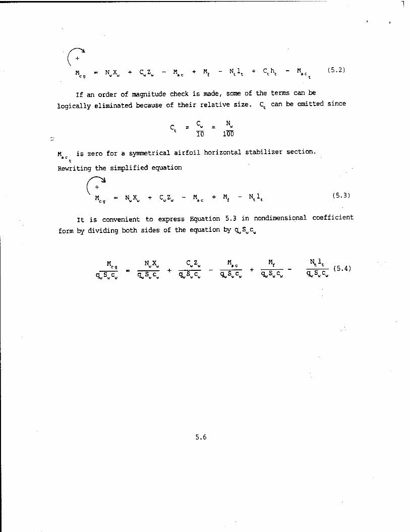
0* "cg - NMXu + CwZv - M.e + Mf - Ntlt + Ctht - MaCt (5.2)
If an order of magnitude check is made, some of the terms can be
logically eliminated because of their relative size. Ct can be omitted since
c N <J, £ W • ; W
t ID 1DD
M is zero for a symmetrical airfoil horizontal stabilizer section. ac
t
Rewriting the simplified equation
M = N X + CZ - K + Mf - N 1 eg v v ww ac t tt (5.3)
It is convenient to express Equation 5.3 in nondimensional coefficient
form by dividing both sides of the equation by qvSvcu
M NX C Z M M. N 1 eg _ y « w w ac +
f _ * * (5 4) q„SwCw ~ qwSvCw q„Swcw " q^c, qvSwcw qwSv,cw
5.6
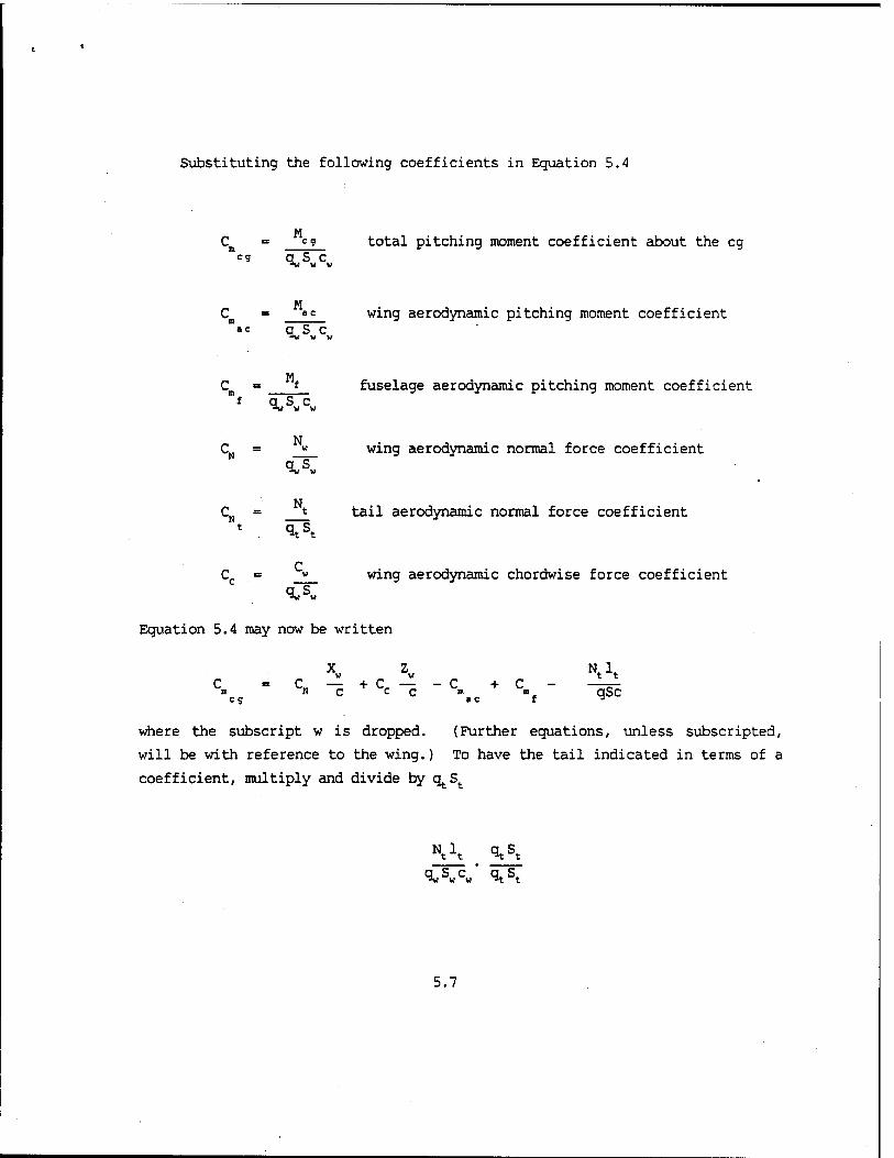
Substituting the following coefficients in Equation 5.4
eg total pitching moment coefficient about the eg ;g q S c ct _
w
M Cn = «c wing aerodynamic pitching moment coefficient
ac q S c
C = f fuselage aerodynamic pitching moment coefficient ™f q S c
CN = M wing aerodynamic normal force coefficient
N CK = t tail aerodynamic normal force coefficient
t q s
C Cc = » wing aerodynamic chordwise force coefficient
*w w
Equation 5.4 may now be written
X Z N„L V w t t
c =c — +c — -c +c- —=- n N c c c » ■ qSc
where the subscript w is dropped. (Further equations, unless subscripted,
will be with reference to the wing.) To have the tail indicated in terms of a
coefficient, multiply and divide by qtSt
5.7

Substituting tail efficiency factor n^. = c^/c^ and designating tail volume
coefficient VH = ltSt/cS Equation 5.5 becomes
" c„ — + cr — - c + c - cM v„ n I N C CCB n NHX eg «eft
BALANCE EQUATION (5.6)
Equation 5.6 is referred to as the equilibrium equation in pitch. If the
magnitudes of the individual terms in the above equation are adjusted to the
proper value, the aircraft may be placed in equilibrium flight where
C = 0 ID eg
Taking the derivative of Equation 5.6 with respect to CL and assuming
that Xw, Zw, VH and n^ do not vary with CL,
dC»cg - *. xw + dcc zw _ dc*ac dc»£ _ dCNt (STABILITY!
■3c—- Be" -^ He" c- He— ac" 3c~ v« \ !EQUATI0N
:v : / v ,v J <5-7>
WING FUSELAGE TAIL
Equation 5.7 is the stability equation and is related to the stability deriva-
tive C by the slope of the lift curve, a. Theoretically, a
dC dCr dC dC dC c* =a^r =a^Tdc: =adc: ■ ^ ae: (5-8)
« L L a L
Equation 5.8 is only true for a rigid aircraft at low Mach when thrust
effects are small; however, this relationship does provide a useful index of
stability.
5.8

Equation 5.6 and Equation 5.7 determine the two criteria necessary for
longitudinal stability:
Criteria 1. The "aircraft is balanced.
Criteria 2. The aircraft is stable.
The first condition is satisfied if the pitching moment equation can be
forced to C 0 for useful positive values of C, . eg
This condition is achieved by adjusting elevator deflection so that moments
about the center of gravity are zero (i.e., M ■ 0).
The second condition is satisfied if Equation 5.7 or dC /dC has a
negative value. From Figure 5.3, a negative value for Equation 5.7 is
necessary if the aircraft is to be stable. Should a gust cause an angle of
attack increase (and a corresponding increase in C ), a negative C should = s
be produced to return the aircraft to equilibrium, or Ct « 0. The greater
the slope or the negative value, the more restoring moment is generated for an
increase in CL. The slope of dCB/dCL is a direct measure of the "gust
stability" of the aircraft. (In further stability equations, the e.g.
subscript will be dropped for ease of notation).
AIRPLANE IN TRIM AT A USEFUL CL
LESS STABLE
MORE STABLE
FIGURE 5.3. STATIC STABILITY
5.9

If the aircraft is retrinmed from one angle of attack to another, the
basic stability of the aircraft or slope dCB/dCL does not change. Note
Figure 5.4.
FIGURE 5.4. STATIC STABILITY WITH TRIM CHANGE
5.10

However, if moving the eg is changing the values of Xv or Zw, or if VH is
changed, the slope or stability of the aircraft is changed. See Equation 5.7.
For no change in trim setting, the stability curve may shift as in Figure 5.5.
FIGURE 5.5. STATIC STABILITY CHANGE WITH CG CHANGE
5.11
5.6 AIRCRAFT COMPONENT CONTRIBUTIONS TO THE STABILITY EQUATION
5.6.1 The Wing Contribution to Stability
The lift and drag are by definition always perpendicular and parallel to
the relative wind. It is therefore inconvenient to use these forces to obtain
moments, for their arms to the center of gravity vary with angle of attack.
For this reason, all forces are resolved into normal and chordwise forces
whose axes remain fixed with the aircraft and whose arms are therefore
constant.
5.12

/ l>- RESULTANT Z*"1\ AERODYNAMIC
•a / 11 FORCE
!\
RELATIVE WIND
FIGURE 5.6. WING CONTRIBUTION TO STABILITY
Assuming the wing lift to be the airplane lift and the wing's angle of
attack to be the airplane's angle of attack, the following relationship exists
between the normal and lift forces (Figure 5.6)
N = L COS a + D sin a (5.S)
C = D COS a - L Sin a (5.10)
Therefore, the coefficients are similarly related
CN = CL cos a + CDsin a (5.n:
C ■= C„ cos a - C, sin a CD 1« (5.12)
The stability contributions, dC /dC and dCc/dCL, are obtained
5.13

(5.13)
dCN dCL da dCD . He" = HT cos a ~ CL ar sin a + ar sin a + CD ar cos a
c _ D -«- _ n da „<- L _i_ - da
(5.14)
= cos a - CD gg- sin a - g^ sin a - CL ^- cos a
Making an additional assumption that
and that Cn is constant with chanaes in C, p ' L
D Dp n AR e
'he n dCo = 2cL
dC. n AR e
If the angles of attack are small such that cos a = 1.0 and sin a = a,
Equations 5.13 and 5.14 become
<*c ac: = FÄTe CL - CD acrB"a"cLar (5-16)
Examining the above equation for relative magnitude,
CD is on the order of 0.02 to 0.30
5.14

C usually ranges from 0.2 to 2.0 L
da Be, L
is small, < 0.2 radians
is nearly constant at 0.2 radians
is on the order of 0.1 ii AR e
Making these substitutions, Equations 5.15 and 5.16 have magnitudes of
dC g~ - 1 - 0.04 + 0.06 = 1.02 * 1.0 (5.17)
(5.18) dcc 3£- - 0.1 CL - 0.012 - 0.2 - 0.2CL = -0.41
at CT = 2.0 Li ma x
The moment coefficient about the aerodynamic center is invariant with respect
to angle of attack (see definition of aerodynamic center). Therefore
dC si
arr " ° Rewriting the wing contribution of the Stability Equation, Equation 5.7,
dc» x« Zw = — - 0.41 — afc c _ 2Q {5ig)
LWING Lmax
5.15

Fran Figure 5.6 when a increases, the normal force increases and the
chordwise force decreases. Equation 5.19 shows the relative magnitude of
these changes. The position of the eg above or below the aerodynamic center
(ac) has a auch smaller effect on stability than does the position of the eg
ahead of or behind the ac. With eg ahead of the ac, the normal force is
stabilizing. From Equation 5.19, the more forward the eg location, the more
stable the aircraft. With the eg below the ac, the chordwise force is
stabilizing since this force decreases as the angle of attack increases. The
further the eg is located below the ac, the more stable the aircraft or the
more negative the value of dCB/dCL. The wing contribution to stability
depends on the eg and the ac relationship shown in Figure 5.7.
DESTABILIZING
STABILIZING
* en ac DESTABILIZING
MOST STABLE STABILIZING
FIGURE 5.7. CG EFFECT ON WING CONTRIBUTION TO STABILITY
5.16

For a stable wing contribution to stability, the aircraft would be designed
with a high wing aft of the center of gravity.
Fighter type aircraft and most low wing, large aircraft have cg's very
close to the top of the mean aerodynamic chord. Zw/c is on the order of 0.03.
For these aircraft the chordwise force contribution to stability can be
neglected. The wing contribution then becomes
dC X
^ c- (5-20)
WING
5.6.2 The Fuselage Contribution to Stability
The fuselage contribution is difficult to separate from the wing terms
because it is strongly influenced by interference from the wing flow field.
Wind tunnel tests of the wing-body combination are used by airplane designers
to obtain information about the fuselage influence on stability.
A fuselage by itself is almost always destabilizing because the center of
pressure is usually ahead of the center of gravity. The magnitude of the
'destabilization effects of the fuselage requires their consideration in the
equilibrium and stability equations. In general, the effect of combining the
wing and fuselage results in the combination aerodynamic center being forward
of quarter-chord and the C of the combination being more negative than the tc
wing value alone.
dc» -sp- = Positive quantity
L FUSELAGE
5.6.3 The Tail Contribution to Stability
From equation 5.7, the tail contribution to stability was found to be
5.17

dC„
HcT v„ *\
TAIL
For small angles of attack, the lift curve slope of the tail is very nearly
the same as the slope of the normal force curve.
dC dC* i t
dot ~ da (5.22)
Therefore
CN - at°t (5.23)
An expression for o^. in terms of CL is required before solving for dCN /dCL
FIGURE 5.8. TAIL ANGLE OF ATTACK
5.18

From Figure 5.8
o - i + i„ - e (5.24) V w t
Substituting Equation 5.24 into 5.23 and taking the derivative with respect to
CL, where au •= dCL/do
/ dav de\ at (1 de 1_\ (5 25)
upon factoring out l/aw
:\ at /. de\
Substituting Equation 5.26 into 5.21, the expression for the tail contribution
becomes
dC_ Jl = _ !l / 1 _ de\ vH
TAIL
The value of at/aw is very nearly constant. These values are usually obtained
from experimental data.
The tail volume coefficient, VH, is a term determined by the geometry of
the aircraft. To vary this term is to redesign the aircraft.
V . ±l!l (5.28) H CS
The further the tail is located aft of the eg (increase lt) or the greater the
tail surface area (St), the greater the tail volume coefficient (V„), which
increases the tail contribution to stability.
5.19

The expression, r^ , is the ratio of the tail dynamic pressure to the wing
dynamic pressure and ry varies with the location of the tail with respect to
wing wake, prop slipstream, etc. For power-off considerations, r^ varies from
0.65 to 0.95 due to boundary layer losses.
The term (1 - de/da) is an important factor in the stability contribution
of the tail. Large positive values of de/da produce destabilizing effects by
reversing the sign of the term (1 - de/da) and consequently, the sign of
dC./dCL . Tail
For example, at high angles of attack the F-104 experiences a sudden
increase in de/da. The term (1 - de/da) goes negative causing the entire tail
contribution to be positive or destabilizing, resulting in aircraft pitchup.
The stability of an aircraft is definitely influenced by the wing vortex
system. For this reason, the downwash variation with angle of attack should
be evaluated in the wind tunnel.
The horizontal stabilizer provides the necessary positive stability
contribution (negative dCn/dCL) to offset the negative stability of the wing-
fuselage combination and to make the entire aircraft stable and balanced
(Figure 5.9).
+
WING AND FUSELAGE
WING
TAIL
FIGURE 5.9. AIRCRAFT COMPONENT CONTRIBUTIONS TO STABILITY
5.20
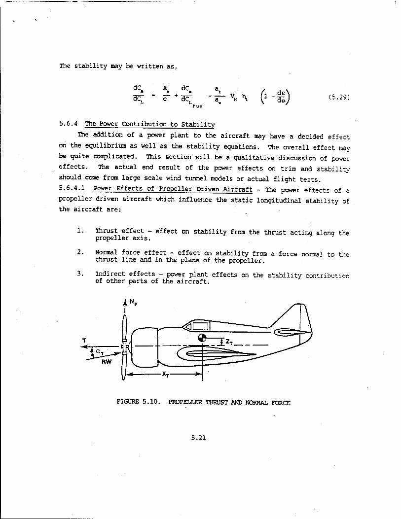
The stability may be written as,
dc. dC
-T- v« \ rut
(> -*) :s.29i
5.6.4 The Power Contribution to Stability
The addition of a power plant to the aircraft may have a decided effect
on the equilibrium as well as the stability equations. The overall effect may
be quite complicated. This section will be a qualitative discussion of power
effects. The actual end result of the power effects on trim and stability
should come from large scale wind tunnel models or actual flight tests.
5.6.4.1 Power Effects of Propeller Driven Aircraft - The power effects of a
propeller driven aircraft which influence the static longitudinal stability of
the aircraft are:
1.
2.
3.
Thrust effect - effect on stability from the thrust acting along the propeller axis.
Normal force effect - effect on stability from a force normal to the thrust line and in the plane of the propeller.
Indirect effects - power plant effects on the stability contribution of other parts of the aircraft.
FIGURE 5.10. PROPELLER THRUST AND NORMAL FORCE
5.21
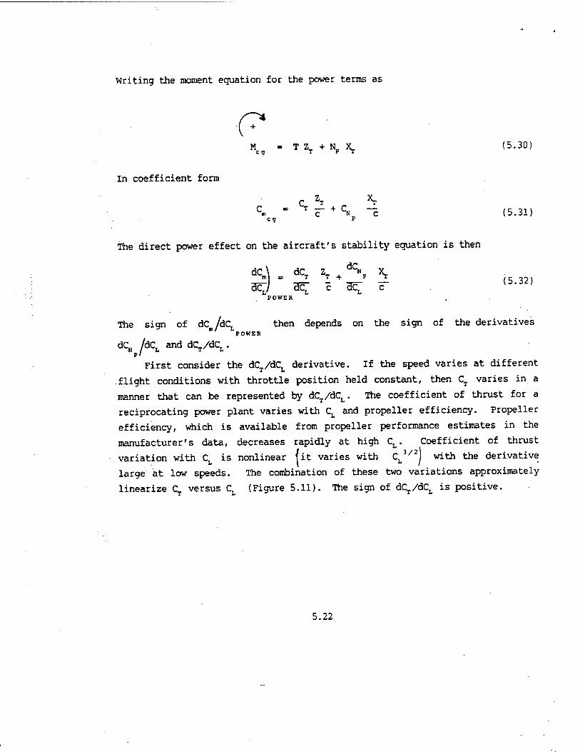
Writing the moment equation for the power terms as
0* M « T 2, + N„ 1 (5.30) CQ T P T
In coefficient form
C ZT n ** c* = T c~ + CN ~c (5.31)
c9 p
The direct power effect on the aircraft's stability equation is then
dC„ (5.32)
dC„\ . dCT ZT + ^NP *T
BC^/ a^ c ac^ C POWER
The sign of dc/dCL then depends on the sign of the derivatives POWER
dCN /dCL anddCT/dCL. p'
First consider the dCVdC, derivative. If the speed varies at different T L
.flight conditions with throttle position held constant, then CT varies in a
manner that can be represented by dCT/dCL. The coefficient of thrust for a
reciprocating power plant varies with CL and propeller efficiency. Propeller
efficiency» which is available from propeller performance estimates in the
manufacturer's data, decreases rapidly at high CL. Coefficient of thrust
variation with CL is nonlinear fit varies with CL3/2j with the derivative
large at low speeds. The combination of these two variations approximately
linearize CT versus CL (Figure 5.11). The sign of dCT/dCL is positive.
5.22

FIGURE 5.11. COEFFICIENT OF THRUST CURVE FOR A RECIPROCATING POWER PLANT WITH PROPELLER
The derivative dCN /dCL is positive since the normal propeller force
increases linearly witl? the local angle of attack of the propeller axis, o^.
The direct power effects are then destabilizing if the eg is as shown in
Figure 5.10 where the power plant is ahead and below the eg. The indirect
power effects must also be considered in evaluating the overall stability
contribution of the propeller power plant. No attempt will be made to
determine their quantitative magnitudes. However, their general influence on
the aircraft's stability and trim condition can be great.
5.6.4.1.1 Increase in angle of downwash, e. Since the normal force on
the propeller increases with angle of attack under powered flight, the
slipstream is deflected downward, netting an increase in downwash on the tail.
The downwash in the slipstream will, increase more rapidly with the angle cf
attack than the downwash outside the slipstream. The derivative dc/da has a
positive increase with power. The term (1 - dc/da) in Equation 5.27 is
reduced causing the tail trim contribution to be less negative or less stable
than the power-off situation.
5.6.4.1.2 Increase of r^ = i^/%)- The dynamic pressure, q,., of the
tail is increased by the slipstream and h^ is greater than unity. From
equation 5.27, the increase of \ with an application of power increases the
tail contribution to stability.
Both slipstream effects mentioned above may be reduced by locating the
5.23
horizontal stabilizer high on the tail and out of the slipstream at operating
angles of attack.
5.6.4.2 Power effects of the turbojet/turbofan/ramjet. The magnitude
of the power effects on jet powered aircraft are generally smaller than on
propeller driven aircraft. By assuming that jet engine thrust does not change
with velocity or angle of attack, and by assuming constant power settings,
smaller power effects would be expected than with a similar reciprocating
engine aircraft.
There are three major contributions of a jet engine to the equilibrium
static longitudinal stability of the aircraft. These are:
1. Direct thrust effects.
2. Normal force effects at the air duct inlet and at angular changes in the duct.
3. Indirect effects of induced flow at the tail.
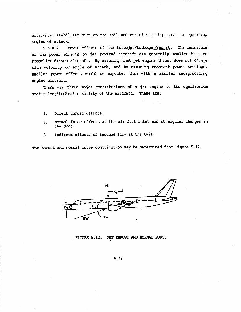
The thrust and normal force contribution may be determined from Figure 5.12.
RW
FIGURE 5.12. JET THRUST AND NORMAL FORCE
5.24
Writing the equation
"eg - ^T +t*T *T <5-33>
or
C„ " qicZT+CNT F (5'34>
eg ^ T
With the aircraft in unaccelerated flight, the dynamic pressure is a function of lift coefficient.
W q~ CLS (5.35)
Therefore,
C = r, r C, + C — (5.36) m W C L N C eg T
If thrust is considered independent of speed, then
dC,
ac: = wc" + acr c" (5-37) L 1»
The thrust contribution to stability then depends on whether the thrust line
is above or below the eg. Locating the engine below the eg causes a
destabilizing influence. The normal force contribution depends on the sign of the derivative
dCN /dCL. The normal force 1^, is created at the air duct inlet to the
turbojet engine. This force is created as a result of the momentum change of
the free stream which bends to flow along the duct axis. The magnitude of the
5.25
force is a function of the engine's airflow rate, Wa, and the angle o^ between
the local flow at the duct entrance and the duct axis.
W N, = Y U0 «^ (5.38)
With an increase in o^, Nj will increase, causing dCN/dCL to be positive.
The normal force contribution will be destabilizing if the inlet duct is
ahead of the center of gravity. The magnitude of the destabilizing moment
will depend on the distance the inlet duct is ahead of the center of gravity.
For a jet engine to definitely contribute to positive longitudinal
stability (dCm/dCL negative), the jet engine would be located above and behind
the center of gravity.
The indirect contribution of the jet unit to longitudinal stability is
the effect of the jet induced downwash at the horizontal tail. This applies
to the situation where the jet exhaust passes under or over the horizontal
tail surface. The jet exhaust as it discharges from the tailpipe spreads
outward. Turbulent mixing causes outer air to be drawn in towards the exhaust
area. Downwash at the tail may be affected. The F-4 is a good example where
entrained air from the jet exhaust causes downwash angle at the horizontal
tail.
5.6.4.3 Power Effects of Rocket Aircraft. Rocket powered aircraft such as
the Space Shuttle, and rocket augmented aircraft such as the C-130 with JATO
installed, can be significantly affected longitudinally depending on the
magnitude of the rocket thrust involved. Since the rocket system carries its
oxidizer internally, there is no inlet or incoming mass flow and no normal
force contribution. The thrust contribution may be determined from Figure
5.13.
5.26

1 ZR (EQUIVALENT)
1
FIGURE 5.13. ROCKET THRUST EFFECTS
Writing the equation
<? TRZR
WC9 - TRZ
R or C»cg = qSc"
(5.39)
Assuming that the rocket thrust is constant with changes in airspeed, the
dynamic pressure is a function of lift coefficient.
TRZECT
q = JL therefore C„ = -^
and
dc«
Be1 T Z F R
W C (5.40)
POWER
From the above discussion, it can be seen that several factors are
important in deciding the power effect on stability. Each aircraft must be
examined individually. This is the reason that aircraft are tested for
stability in several configurations and at different power settings.
5.27

5.7 THE NEUTRAL POINT
The stick fixed neutral point is defined as the center of gravity
position at which the aircraft displays neutral stability or where
dC /dCt - 0
The symbol h is used for the center of gravity position where
eg
c (5.41)
The stability equation for the powerless aircraft is
dC m dC
-^C— "a" VH >\ 1
rus
de\ " 35/ (5,29)
Looking at the relationship between eg and ac in Figure 5.14
FIGURE 5.14. CG AND AC RELATIONSHIP
X w C~
h - (5.42)
5.28

Substituting Equation 5.42 into Equation 5.29,
dC X . dC a. -» = h - "Vc + "w* - at ( de\ ,, ,,, ■3c[ — ac^ T VH ^ \X " Hi) (5-43)
Fus
If we set dCB/dCL = 0, then h s hn and Equation 5.43 gives
. X dC ^ a, n = ac— in + t n — acr_Tir VH \ f-M) (5-44)
C ~~LFUS
This is the eg location where the aircraft exhibits neutral static stability: the neutral point.
Substituting Equation 5.44 back into Equation 5.43, the stick-fixed sta- bility derivative in terms of eg position becomes
dC = h - h„ (5.45) Hc7 " n
The stick-fixed static stability is equal to the distance between the eg
position and the neutral point in percent of the mean aerodynamic chord.
"Static Margin" refers to the same distance, but is positive in sign for
a stable aircraft.
Static Margin = h - h (5.46) n
It is the test pilot's responsibility to evaluate the aircraft's handling
qualities and to determine the acceptable static margin for the aircraft.
5.8 ELEVATOR POWER
For an aircraft to be a usable flying machine, it must be stable and
5.29

balanced throughout the useful CL range. For trimmed, or equilibrium flight,
C must be zero. Some means must be available for balancing the various
terms in Equation 5.47
X z c» - cN"i + Cc-c -c» +c* - (at ^ v« M (5-47)
eg ac f
(Equation 5.47 is obtained by substituting Equation 5.23 into Equation 5.6.)
Several possibilities are available. The center of gravity could be
moved fore and aft, or up and down, thus changing Xw/c or Zw/c. However, this
would not only affect the equilibrium lift coefficient, but would also change
dCm/dCL in Equation 5.48. This is undesirable.
dC dCM X dCr Z dC a. / ,.\
<- as fa- c-*ar-i; ». M1-*) <5-<»> F u s
Equation 5.48 is obtained by substituting Equation 5.26 into Equation
5.7. The pitching moment coefficient about the aerodynamic center could be
changed by effectively changing the camber of the wing by using trailing edge
flaps as is done in flying wing vehicles. On the conventional tail-to-the
rear aircraft, trailing edge wing flaps are ineffective in trimming the
pitching moment coefficient to zero. The combined use of trailing edge flaps
and trim from the tail may serve to reduce drag, as used on some sailplanes
and the F-5E.
The remaining solution is to change the angle of attack of the horizontal
tail to achieve a jCm = 0) without a change to the basic aircraft
stability.
The control means is either an elevator on the stabilizer or an all
moving stabilizer (slab or stabilator). The slab is used on most high speed
aircraft and is the most powerful means of longitudinal control.
5.30
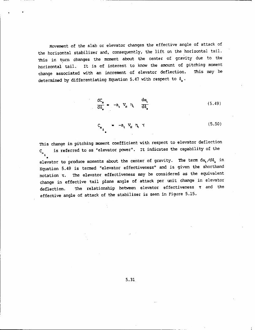
Movement of the slab or elevator changes the effective angle of attack of
the horizontal stabilizer and, consequently, the lift on the horizontal tail.
This in turn changes the moment about the center of gravity due to the
horizontal tail. It is of interest to know the amount of pitching moment
change associated with an increment of elevator deflection. This may be
determined by differentiating Equation 5.47 with respect to 6e .
dC da
e •
C = -a, v„ n T (5.50) o e
This change in pitching moment coefficient with respect to elevator deflection
C is referred to as "elevator power". It indicates the capability of the i e
elevator to produce moments about the center of gravity. The term doct/d6e in
Equation 5.49 is termed "elevator effectiveness" and is given the shorthand
notation x. The elevator effectiveness may be considered as the equivalent
change in effective tail plane angle of attack per unit change in elevator
deflection. The relationship between elevator effectiveness x and the
effective angle of attack of the stabilizer is seen in Figure 5.15.
5.31
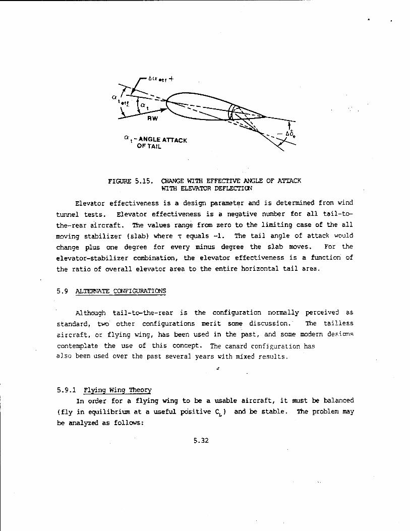
■£««..+
Qt~ ANGLE ATTACK OF TAIL
FIGURE 5.15. CHANGE WITH EFFECTIVE ANGLE OF ATTACK WITH ELEVATOR DEFLECTION
Elevator effectiveness is a design parameter and is determined from wind
tunnel tests. Elevator effectiveness is a negative number for all tail-to-
the-rear aircraft. The values range from zero to the limiting case of the all
moving stabilizer (slab) where x equals -1. The tail angle of attack would
change plus one degree for every minus degree the slab moves. For the
elevator-stabilizer combination, the elevator effectiveness is a function of
the ratio of overall elevator area to the entire horizontal tail area.
5.9 ALTERNATE CONFIGURATIONS
Although tail-to-the-rear is the configuration normally perceived as
standard, two other configurations merit some discussion. The tailless
aircraft, or flying wing, has been used in the past, and some modern desions
contemplate the use of this concept. The canard configuration has
also been used over the past several years with mixed results.
5.9.1 Flying Wing Theory
In order for a flying wing to be a usable aircraft, it must be balanced
(fly in equilibrium at a useful positive CL) and be stable. The problem may
be analyzed as follows:
5.32
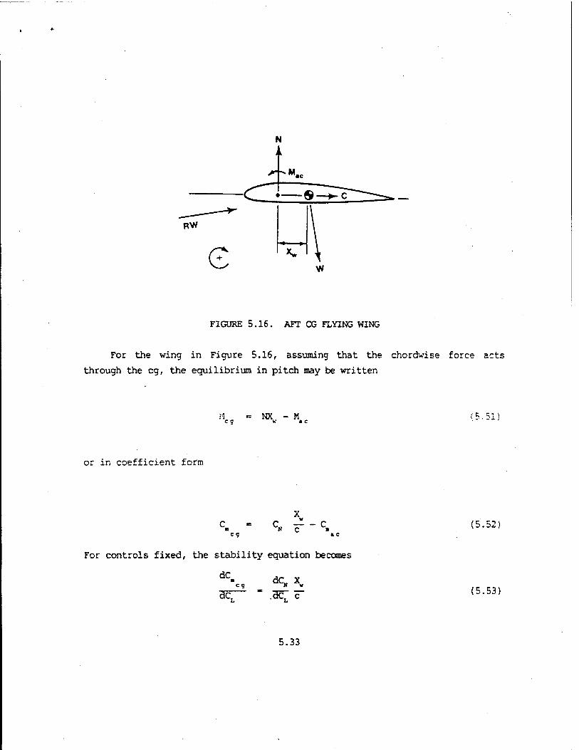
FIGURE 5.16. AFT CG FLYING WING
For the wing in Figure 5.16, assuming that the chordwise force acts
through the eg, the equilibrium in pitch may be written
eg = NX - M (5.51!
or in coefficient form
= 9 "N C
For controls fixed, the stability equation becomes
dC <=S
dcT dC„ X H v
.3c~ c~ I*
(5.52)
(5.53)
5.33

Equations 5.52 and 5.53 show that the wing in Figure 5.16 is balanced and
unstable. To make the wing stable, or dcydc^ negative, the center of gravity
must be ahead of the wing aerodynamic center. Making this eg change, however,
now changes the signs in Equation 5.51 . The equilibrium and stability
equations become
= 9 - c,
» c (5.54)
dC = 9
HCT
dc. x N v
Hc^ c~ (5.55)
The wing is now stable but unbalanced. The balanced condition is possible
with a positive C a c
Three methods of obtaining a positive C are: * c
1. Use a negative camber airfoil section. The positive C will qive a c
a flying wing that is stable and balanced (Figure 5.17).
RW
FIGURE 5.17. NEGATIVE CAMBERED FLYING WING
5.34

This type of wing is not realistic because of unsatisfactory dynamic
characteristics, small eg range, and extremely low CL maximum capability.
2. A reflexed airfoil section reduces the effect of camber by creating a
download near the trailing edge. Similar results are possible with
an upward deflected flap on a symmetrical airfoil.
3. A symmetrical airfoil section in combination with sweep and wingtip
washout (reduction in angle of incidence at the tip) will produce a
positive Cm by virtue of the aerodynamic couple produced between n a c
the downloaded tips and the normal lifting force. This is shown in
Figure 5.18.
5.35

LIFT
SPANWISE LIFT DISTRIBUTION
c~5&
FROM ABOVE:
VECTOR UP FROM THE SIDE:
INNER PANEL
-^e TOTAL
-$ OUTER PANEL
mac
RESULT: BALANCED AND STABLE
H mac
i mac
FIGURE 5.18. THE SWEPT AND TWISTED FLYING WING
Figure 5.19 shows idealized C.^ versus ^ for various wings in a control
fixed position. Only two of the wings are capable of sustained flight.
5.36

NO SWEEP
UNSTABLE AFT eg
*- C. 0
SYMETRICAL SWEEPBACK WASHOUT
UNSTABLE AFTcfl
SYMETRICAL
NO SWEEP
UNSTABLE AFT eg
*-CL 0
POSITIVE CAMBER
NO SWEEP
UNSTABLE AFT eg
*- C,
REFLEXED TRAILING EDGE
FIGURE 5.19. VARIOUS FLYING WINGS
5.37

5.9.2 The Canard Configuration
Serious work on aircraft with the canard configuration has been sporadic
from the tine the Wright brothers' design evolved into the tail to the rear
airplanes of World War I, until the early 1970's. One of the first successful
canard airplanes in quantity production was the Swedish JA-37 "Viggen"
fighter. Other projects of significance were the XB-70, the Mirage Milan, and
the TU-144. The future seems to indicate that we may see more of the canard
configuration, as evidenced by the X-29 Forward Swept Wing project.
WING AERO CENTER
RUTAN LONG EZE
FIGURE 5.20. BALANCE COMPARISON
5.9.2.1 The Balance Equation. From Figure 5.20 the balance equation can be
written as follows:
C M - -NX +CZ -M + M- + N 1 + C h - M eg ww ww a c t tt t ^ »c (5.56)
5.38

Simplifying assumptions are
Ctht and K4C are small and may be neglected
M c - C9 ■ - ■c," 5-SvCw
-
Combining Terms:
xu c ■ -c. ^ + c
B H C c
C9
z c"
Xw Zw Ntlt qtSt
BALANCE (5.56) - C + C + C, V, h EQUATION
■ It Ft H T
5.9.2.2 The Stability Equation. Although the canard can be a balanced
configuration, it remains to be seen if it demonstrates static stability or "gust stability". By taking the derivative with respect to CL, Equation 5.58 becomes
dC.0 - dCN Xv + dCC 2« + dC"f + dC\ -„^L. " ~ " _L + -Ji — + a=-l + —-1 v n STABILITY (5.59) HCT" ac; c ac; c HC7 Hc7 H n, BQ^TJON
Equation 5.59 indicates that the normal (or lift) force of the wing now has a
stabilizing influence (negative in sign), and the canard term is destabilizing
due to its positive sign. It is obviously a misnomer to call the canard a
horizontal stabilizer, because in reality it is a "destabilizer"! The degree
of instability must be overcome by the wing-fuselage combination in order for
the airplane to exhibit positive static stability dCB/dCL (negative in
sign). This is shown graphically in Figure 5.21.
5.39

FIGURE 5.21. CANARD EFFECTS CN dCB/dCL
5 9 2.3 -r-- ^h,H« to Stability, jn a n^er simlar to the ™y a
rM ^tiThorisontal tail experiences a downwash field frc the «*. rfth.
„in,, the canard will see upwash ahead of the wing. A», v^sh f.eld has a
^labilisin, effect on longitudinal stability because it »aKes the tail ter»
in the stability equation note positive. The tail contribution fro. Equation 5.6! can be examined for the effects
of upwash, e'
dC,
acrv" * d (ate^)
dcT"
do,. V
H K - at VH *t ac:
The tail angle of attack, V can be expressed in terms of incidence and
upwash, as described in Figure 5.22.
5.40

Therefore
FIGURE 5.22. CANARD ANGLE OF ATTACK
- it - e' - a, - iv
a - i + i„ + C w w t
The tail contribution now becomes
d(aw - iw + it + C)
W\ ae;
„ , /l A de' daA
/l dc' 1 \
(5.62)
(5.63)
5.41

Therefore,
dC L a,
L w x v '
It is extremely important to note that the upwash and downwash
interaction between the canard and the wing are critical to the success of the
design. The wing will see a downwash field from the canard over a portion of
the leading edge. Aerodynamic tailoring and careful selection of the airfoil
is required for the airplane to meet its design objectives at all canard
deflections and flap settings on the wing. Designs which tend to be
tandem-wing become even more sensitive to upwash and downwash.
5.10 STABILITY CURVES
Figure 5.23 is a wind tunnel plot of CB versus CL for an aircraft tested
under two eg positions and two elevator positions.
Assuming the elevator effectiveness and the elevator power to be
constant, equal elevator deflections will produce equal moments about the eg.
Points A and B represent the same elevator deflection corresponding to the
C needed to maintain equilibrium. For an elevator deflection of 10°, in the m eg ,
aft eg condition, the aircraft will fly in equilibrium or trim at point B. If
the eg is moved forward with no change to the elevator deflection the
equilibrium is now at A and at a new CL. Note the increase in the stability
of the aircraft (greater negative slope of dCB/dCL).
For equilibrium at a lower CL or at A without changing the eg, the
elevator is deflected to 5°. The stability level of the aircraft has not
changed (same slope).
A cross plot of Figure 5.23 is elevator deflection versus CL for Cn = 0.
This is shown in Figure 5.24. The slopes of the eg curves are indicative of
the aircraft's stability.
5.42

• NOSE UP ^\>*"^"~ b»~ +1°
cn 0 \^SV\A •^* —— C,
\ \\^r"5,"+s
\\\\ AFT CO
NOSE DOWN
\ FWDcg
FWDcg AFT CO
FIGURE 5.23. eg AND S# VARIATION OF STABILITY
FWDcg
AFT eg
FIGURE 5.24. S VERSUS Ct
5.11 FLIGHT TEST RELATIONSHIP
The stability equation previously derived cannot be directly used in
flight testing. There is no aircraft instrumentation which will measure the
change in pitching moment coefficient with change in lift coefficient or angle
of attack. Therefore, an expression involving parameters easily measurable in
flight is required. This expression should relate directly to the stick-fixed
longitudinal static stability, dCB/dCL, of the aircraft.
5.43

The external moment acting longitudinally on an aircraft is
M - f (U, a, a, Q, S. )
Assuming that the aircraft is in equilibrium and in unaccelerated flight, then
M - f (a, SJ (5.65)
Therefore, using a Taylor series expansion,
and
where
AM . |M Aa+ |« as 3a 3S# • (5.66]
C = C Aa + C AS =0 (5.67) a 6
La - a — a = a o
A5 = 5 - 6 =5 e e • e o
assuming
ao = 0
6 = 0 O
5.44

The elevator deflection required to maintain equilibrium is,
Cn a
8. - - c^— (5.68)
Taking the derivative of Se with respect to CL
dS e
dC , B da
Ha~ HOT Li
dC
K ■ c a i
(5.69)
In terms of the.static margin, the flight test relationship is,
f!i - h" "h = static margin (5>70) dcT C elevator power
D
The amount of elevator required to fly at equilibrium varies directly as the
amount of static stick-fixed stability and inversely as the amount of elevator
power.
5.12 LIMITATION TO DEGREE OF STABILITY
The degree of stability tolerable in an aircraft is determined by the
physical limits of the longitudinal control. The elevator power and amount of
elevator deflection is fixed once the aircraft has been designed. If the
relationship between 8e required to maintain the aircraft in equilibrium
flight and CL -is linear, then the elevator deflection required to reach any CL
is,
d8
«. - 5. + HCT CL
(5-71) Zero L
Lift
5.45

The elevator stop determines the absolute limit of the elevator
deflection available. Similarly, the elevator must be capable of bringing the
airplane into equilibrium at CL
Recalling Equation 5.69
L Max
dC
dS HcT e _ I (5.69) 3cT " c
&
Substituting Equation 5.69 into 5.71 and solving for dCB/dCL corresponding
tOCL Wax
L Max
(5.72)
Given a maximum CL required for landing approach, Equation 5.72 represents the
maximum stability possible, or defines the most forward eg position. A eg
forward of this point prevents obtaining maximum CL with limit elevator.
If a pilot were to maintain CL for the approach, the value of dCB/dCL Max
corresponding to this CL would be satisfactory. However, the pilot usually Max
desires additional elevator deflection to compensate for gusts and to flare the aircraft. This requirement then
dictates a dC /dCt less than the value required for CL only. "/ LM«x «»*
In addition to maneuvering the aircraft in the landing flare, the pilot
must adjust for ground effect. The ground imposes a boundary condition which
affects the downwash associated with the lifting action of the wing. This
ground interference places the horizontal stabilizer at a reduced negative
angle of attack. The equilibrium condition at the desired CL is disturbed.
5.46

To maintain the desired CL, the pilot must increase f>m to obtain the original
tail angle of attack. The maximum stability dCB/dCL must be further reduced
to obtain additional S# to counteract the reduction in downwash.
The three conditions that limit the amount of static longitudinal
stability or most forward eg position for landing are:
1. The ability to land at high CL in ground effect.
2. The ability to maneuver at landing CL (flare capability)
3. The total elevator deflection available.
Figure 5.25 illustrates the limitation in dCm/dCL ' Hri
y- 6. LIMIT
TÄ6~ FOR GROUND EFFECT / "TAS, FOR*MANEUVERING AT C^
FIGURE 5.25. LIMITATIONS ON dC /dC, •/' Max
5.47

5.13 STICK-FREE STABILITY
The name stick-free stability comes from the era of reversible control
systems and is that variation related to the longitudinal stability which an
aircraft could possess if the longitudinal control surface were left free to
float in the slipstream. The control force variation with a change in
airspeed is a flight test measure of this stability.
If an airplane had an elevator that would float in the slipstream when
the controls were free, then the change in the pressure pattern on the
stabilizer would cause a change in the stability level of the airplane. The
change in the tail contribution would be a function of the floating
characteristics of the elevator. Stick-free stability depends on the elevator
hinge moments caused by aerodynamic forces which affect the total moment on
the elevator.
An airplane with an irreversible control system has very little tendency
for its elevator to float. Yet the control forces presented to the pilot
during flight, even though artificially produced, appear to be the effects of
having a free elevator. If the control feel system can be altered
artificially, then the pilot will see only good handling qualities and be able
to fly what would normally be an unsatisfactory flying machine.
Stick-free stability can be analyzed by considering the effect of freeing
the elevator of a tail-to-the-rear aircraft with a reversible control system.
In this case, the feel of stick-free stability would be indicated by the stick
forces required to maintain the airplane in equilibrium at some speed other
than trim.
The change in stability due to freeing the elevator is a function of the
floating characteristics of the elevator. The floating characteristics depend
upon the elevator hinge moments. These moments are created by the change in
pressure distribution over the elevator associated with changes in elevator
deflection and tail angle of attack.
The following analysis looks at the effect that pressure distribution has
on the elevator hinge moments, the floating characteristics of the elevator,
and the effects of freeing the elevator.
Previously, an expression was developed to measure the longitudinal
5.48
static stability using elevator surface deflection, S#. This expression
represented a controls locked or stick-fixed flight test relationship where
the aircraft was stabilized at various lift coefficients and the elevator
deflections were then measured at these equilibrium values of CL. The
stick-free flight test relationship will be developed in terms of stick force,
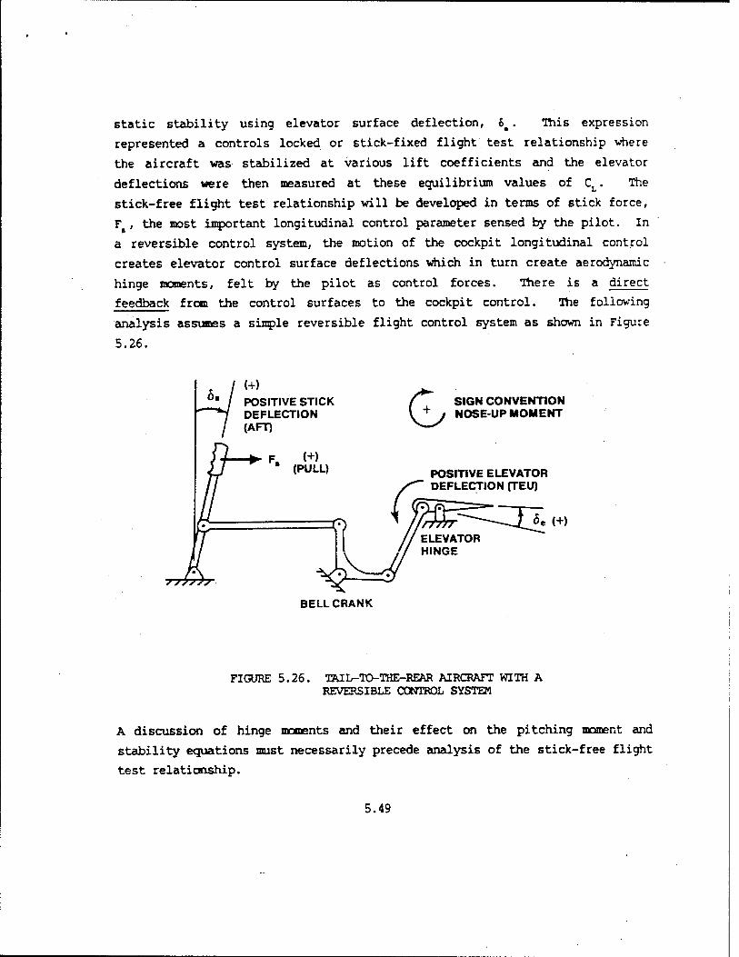
F , the most important longitudinal control parameter sensed by the pilot. In
a reversible control system, the motion of the cockpit longitudinal control
creates elevator control surface deflections which in turn create aerodynamic
hinge moments, felt by the pilot as control forces. There is a direct
feedback from the control surfaces to the cockpit control. The following
analysis assumes a simple reversible flight control system as shown in Figure
5.26.
(+) POSITIVE STICK DEFLECTION (AFT)
F, (+) * (PULL)
G SIGN CONVENTION NOSE-UP MOMENT
POSITIVE ELEVATOR DEFLECTION (TEU)
5e (+)
BELL CRANK
FIGURE 5.26. TAIL-TO-THE-REAR AIRCRAFT WITH A REVERSIBLE CONTROL SYSTEM
A discussion of hinge moments and their effect on the pitching moment and
stability equations must necessarily precede analysis of the stick-free flight
test relationship.
5.49

5.13.1 Aerodynamic Hinge Moment
An aerodynamic hinge moment is a moment generated about the control
surface as a consequence of surface deflection and angle of attack. Figure
5.27 depicts the moment at the elevator hinge due to tail angle of attack
(6 - 0). Note the direction that the hinge moment would tend to rotate the
elevator if the stick were released.
HINGE LINE
<*,{+)
He<+)
FIGURE 5.27. HINGE MOMENT DUE TO TAIL ANGLE OF ATTACK
If the elevator control were released in this case, the hinge moment, H# would
cause the elevator to rotate trailing edge up (TEU). Since the elevator TEU
was previously determined to be positive, a positive hinge moment is that
which, if the elevator control were released would cause the elevator to
5.50

deflect TEU. The general hinge moment equation may be expressed as
Ch Qt s. c. (5.73)
Where S is elevator surface area aft of the hinge line and c# is the root
mean square chord of the elevator aft of the hinge line. The hinge moments
due to elevator deflection, 6#, and tail angle of attack, o^ , will be analyzed
separately and each expressed in coefficient form.
5.13.2 Hinge Moment Due to Elevator Deflection
Figure 5.28 depicts the pressure distribution due to elevator deflection.
This condition assumes a,. ■ 0. The elevator is then deflected, 6t. The
resultant force aft of the hinge line produces a hinge moment, H#, which is
due to elevator deflection.
RW,
at = o
HINGE LINE
He(+)
FIGURE 5.28. HINGE MOMENT DUE TO ELEVATOR DEFLECTION
Given the sign convention specified earlier, Figure 5.29 depicts the
relationship of hinge moment coefficient to elevator deflection, where
5.51

(TED) Ö. (TEU)
a, = o
FIGURE 5.29. HINGE MOMENT COEFFICIENT DUE TO ELEVATOR DEFLECTION
»st hinge nent curves are nonlinear at the extremes of elevator deflection
o' tail angle of attack. The boundaries shown on Figure 5.29 signify that
only the linear portion of the curves is considered. The usefulness of this
«sunption will be apparent when the effect of elevator deflection ano tail
angle of attack are combined. The slope of the curve in Figure 5.29 is C^ , the hinge moment
coefficient due to elevator deflection. It is negative in sign and constant
in the linear region. The term C, is generally called the «restoring" 6 •
moment coefficient.
5 13 3 Hinge Moment Due to Tail Angle of Attack
Figure 5.30 depicts the pressure distribution due to tail angle of
attack. This condition assumes S. « 0. The tail is placed at some angle of
5.52

attack. As in the previous case, the lift distribution produces a resultant
force aft of the hinge line, which in turn generates a hinge moment. The
term, C^ , is generally referred to as the "floating" moment coefficient.
at{+)
HINGE LINE
He(+)
FIGURE 5.30. HINGE MOMENT DUE TO TAIL ANGLE OF ATTACK
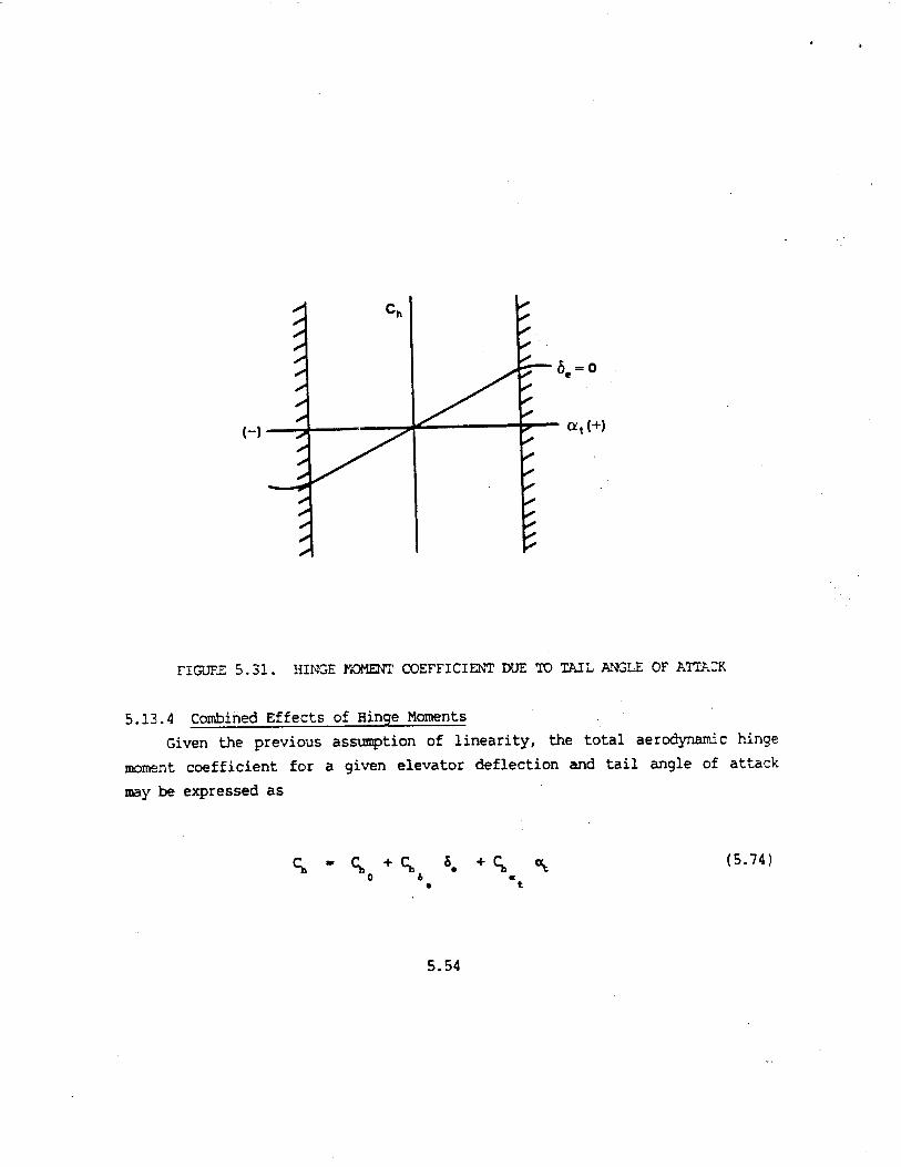
Figure 5.31 depicts the relationship of hinge moment coefficient to tail angle
of attack, where
Ch 1tS.c.
5.53
(-)—■? at{+)
FIGURE 5.31. HINGE MOMENT COEFFICIENT DUE TO TAIL ANGLE OF ATTACK
5.13.4 Combined Effects of Hinge Moments
Given the previous assumption of linearity, the total aerodynamic hinge
moment coefficient for a given elevator deflection and tail angle of attack
may be expressed as
0 & « • t
(5.74)
5.54

Figure 5.32 is a graphical depiction of the above relationship, assuming a
symmetrical tail so that (^ - 0.
FIGURE 5.32. COMBINED HINGE MOMENT COEFFICIENTS
The "e" and "t" subscripts on the restoring and floating hinge moment
coefficients are often dropped in the literature. For the remainder of this
chapter:
Restoring Coefficient
W (5.75)
5.55

Floating Coefficient
8"t - c, (5.76)
Examining a floating elevator, it is seen that the total hinge moment
coefficient is a function of elevator deflection, tail angle of attack, and
mass distribution.
H. " f<5.' Of w> (5.77)
If the elevator is held at zero elevator deflection and zero angle of attack,
there may be some residual aerodynamic hinge moment, C^ If W is the o
weight of the elevator and x is the moment arm between the elevator eg
and elevator hinge line, then the total hinge moment is,
o a 6 ^ (5.78)
HINGE LINE
FIGURE 5.33. ELEVATOR MASS BALANCING REQUIREMENT
5.56
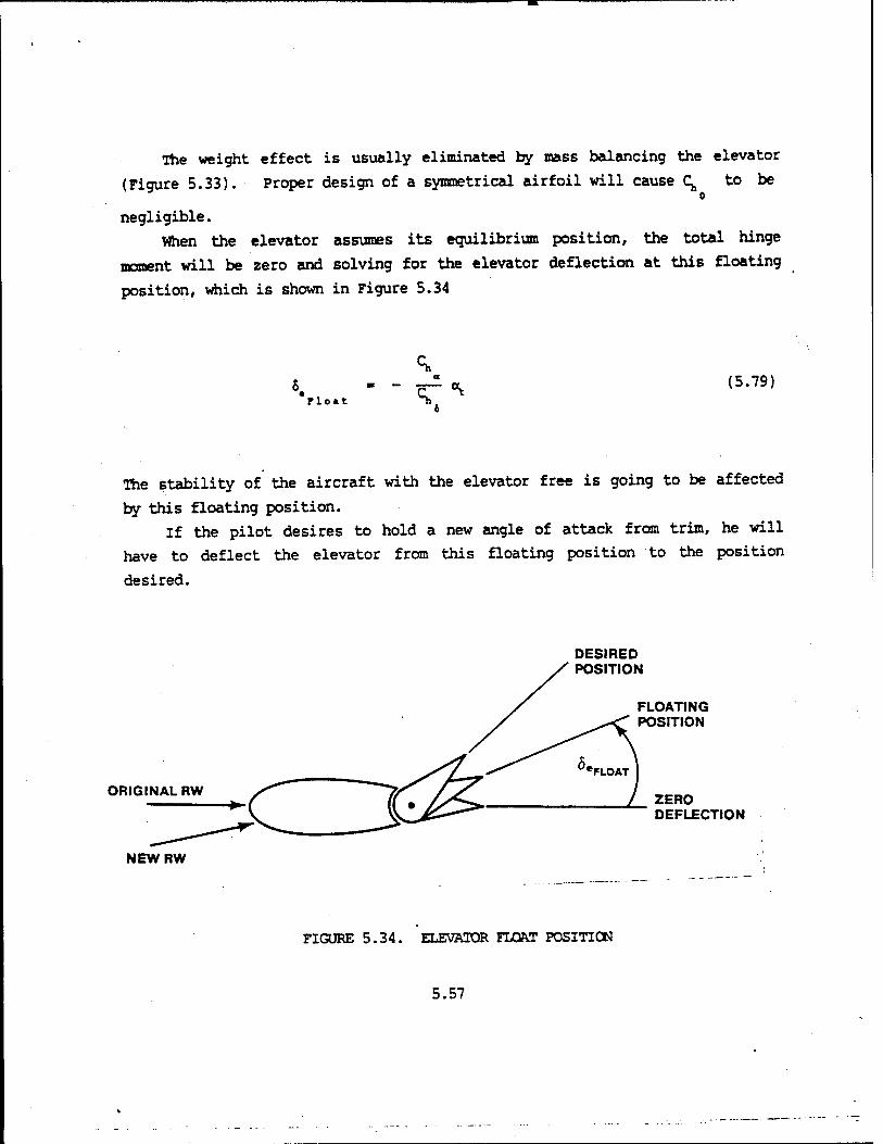
The weight effect is usually eliminated by mass balancing the elevator
(Figure 5.33). Proper design of a symmetrical airfoil will cause C^ to be o
negligible.
When the elevator assumes its equilibrium position, the total hinge
moment will be zero and solving for the elevator deflection at this floating
position, which is shown in Figure 5.34
rio«t
a (5.79)
The stability of the aircraft with the elevator free is going to be affected
by this floating position.
If the pilot desires to hold a new angle of attack from trim, he will
have to deflect the elevator from this floating position to the position
desired.
DESIRED POSITION
ORIGINAL RW
NEWRW
FLOATING POSITION
ZERO DEFLECTION
FIGURE 5.34. ELEVATOR FLOAT POSITION
5.57

The floating position will greatly affect the forces the pilot is
required to use. If the ratio C^/C^ can be adjusted, then the forces
required of the pilot can be controlled.
If r / (^ is small, then the elevator will not float very far and the
stick-free "stability characteristics will be much the sane as those with the
stick fixed. But ^ must be small or the stick forces required to hold
deflection will be unreasonable. The values of C, and C, can be controlled a *
by aerodynamic balance. Types of aerodynamic balancing will be covered in a
later section.
One additional method for altering hing,.» moments is through the use of a trim
tab. There are numerous tab types that will be discussed in a later section.
A typical tab installation is presented in Figure 5.35.
A\ SUCTION DUE TO *'(-)"* TAB DEFLECTION
FIGURE 5.35. ELEVATOR TRIM TAB
5.58
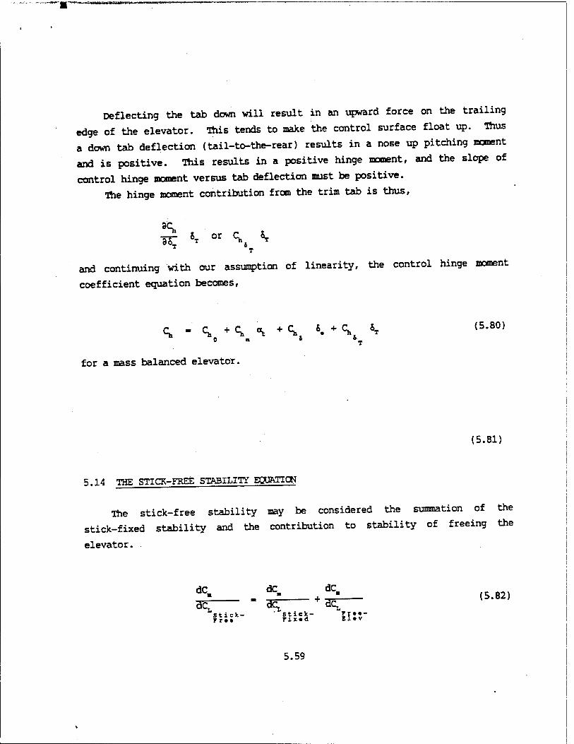
Deflecting the tab down will result in an upward force on the trailing
edge of the elevator. This tends to make the control surface float up. Thus
a down tab deflection (tail-to-the-rear) results in a nose up pitching moment
and is positive. This results in a positive hinge moment, and the slope of
control hinge moment versus tab deflection must be positive.
The hinge moment contribution from the trim tab is thus,
T
and continuing with our assumption of linearity, the control hinge moment
coefficient equation becomes,
0 a 6 °T
for a mass balanced elevator.
(5.80)
(5.81)
5.14 THE STICK-FREE STABILITY EQUATION
The stick-free stability may be considered the summation of the
stick-fixed stability and the contribution to stability of freeing the
elevator.
nay- " suss- 5i:r
5.59

The stability contribution of the free elevator depends upon the elevator
floating position. Equation 5.83 relates to this position
5_ --^ a, (5.83) *rio«t S»,
Substituting for o^ from Equation 5.24
«. - - cT (a- " *• + ** "e) (5'84) 6
Taking the derivative of Equation 5.84 with respect to CL'
d& ^ /i-5s' e ■ - *_ I da
dC, C. V a. (5.85)
Substituting the expression for elevator power, (Equation 5.50) into Equation
5.69 and combining with Equation 5.85.
t <V - - at VH \ ^ (5'50)
dc» - a< BcT a,
Fra* El.v
:*.* (i-&)(^ (5-86)
5.60

Substituting Equation 5.86 and Equation 5.29 into Equation 5.82, the
stick-free stability becomes
dC X dC a«. / . v , ^ v
3^— ■ i- *aj i \ \ (* - «X1" T ^) (5-87) Stick- ru« 4
Ft««
The difference between stick-fixed and stick-free stability is the multiplier
in Equation 5.87 1-TC /C , called the "free elevator factor" which a.' 4
is designated F. The magnitude and sign of F depends on the relative
magnitudes of T and the ratio of (^ /C^ .An elevator with only slight a 4
floating tendency has a small (^ / C^ giving a value of F around unity. a ^ 4
Stick-fixed and stick-free stability are practically the same. If the
elevator has a large floating tendency (ratio of C^ / (^ large), the a 4
stability contribution of the horizontal tail is reduced (dCB/dCL is Stiek-
rr«« less negative). For instance, a ratio of C^/C^ ■ -2 and a T of -.5, the
a 4
floating elevator can eliminate the whole tail contribution to stability.
Generally, freeing the elevator causes a destabilizing effect. With elevator
free to float, the aircraft is less stable.
The stick-free neutral point, h/, is that eg position at which
dC /dCt is zero. Continuing as in the stick-fixed case, the stick-free Stick-
rr«« neutral point is,
X dC a,
C -L Pus
dC a„ / . \
5.61
and
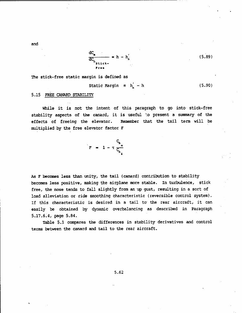
dC_ h-h (5.89)
Stick-
rra*
The stick-free static margin is defined as
Static Margin s h^ - h (5.90)
5.15 FREE CftN&RP STABILITY
While it is not the intent of this paragraph to go into stick-free
stability aspects of the canard, it is useful :-.o present a summary of the
effects of freeing the elevator. Remember that the tail term will be
multiplied by the free elevator factor F
F - 1 - T
\
As F becomes less than unity, the tail (canard) contribution to stability
becomes less positive, making the airplane more stable. In turbulence, stick
free, the nose tends to fall slightly from an up gust, resulting in a sort of
load alleviation or ride smoothing characteristic (reversible control system).
If this characteristic is desired in a tail to- the rear aircraft, it can
easily be obtained by dynamic overbalancing as described in Paragraph
5.17.6.4, page 5.84.
Table 5.1 compares the differences in stability derivatives and control
terms between the canard and tail to the rear aircraft.
5.62
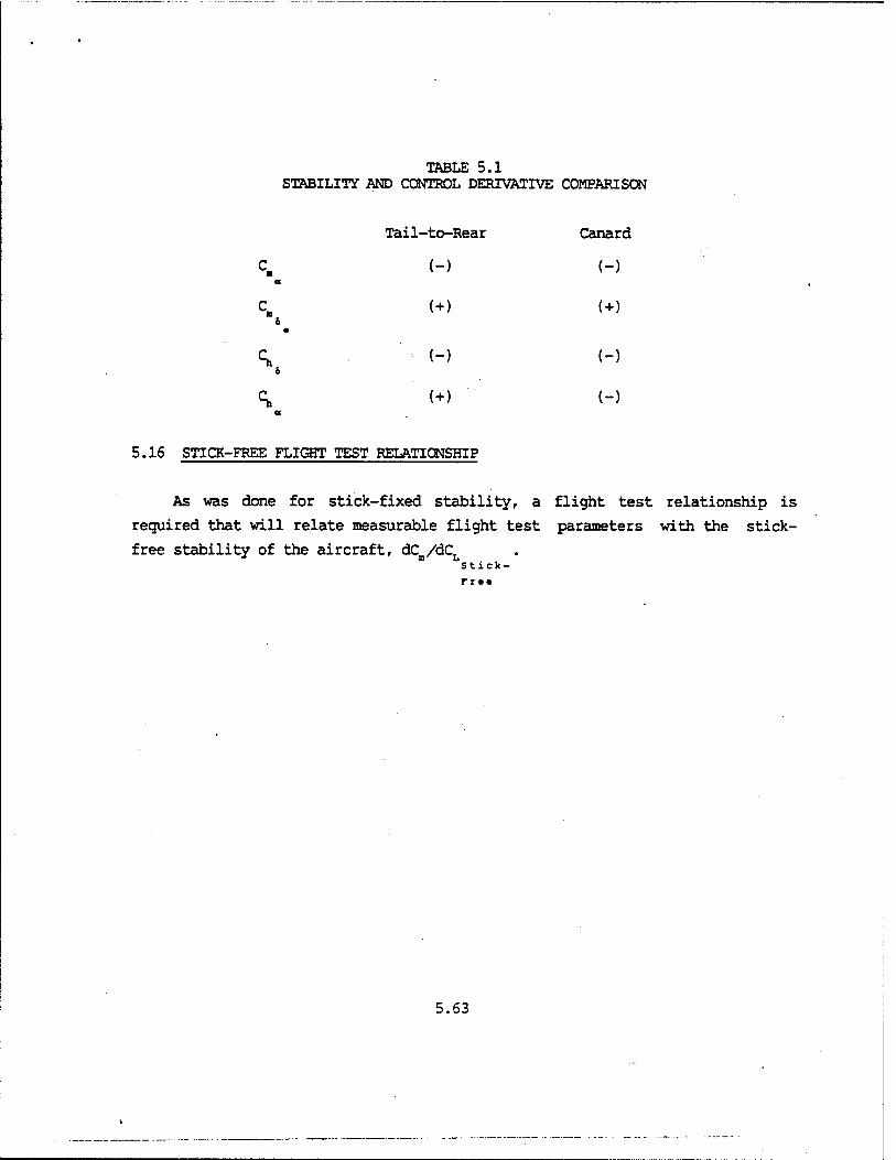
TABLE 5.1 STABILITY AND CONTROL DERIVATIVE COMPARISON
Tail-to-Rear Canard
et (-) (-)
\ (+) (+)
•
(-) (-)
c, (+) (-)
5.16 STICK-FREE FLIGHT TEST RELATIONSHIP
As was done for stick-fixed stability, a flight test relationship is
required that vail relate measurable flight test parameters with the stick-
free stability of the aircraft, dCa/dCL Stick-
rrtt
5.63

XJ* G, - f(a, b, c, d, •,
FIGURE 5.36. ELEVATOR-STICK GEARING
^ , , .^ a stick deflected with a stick force F,. The control
j"—J^—--*■ ^iot *-* *■9earing to * e"a rt 5 IT ^elevator deflects and the aerodynamic pressure proouces a
r/e .L" at I elevator that exactly balances the _* P-duced by the
pilot with force F,.
F.l. - - Gx H.
If the length 1, 1 is included with the gearing, the stick force becomes
r. - - 6H. (5.91)
5.64
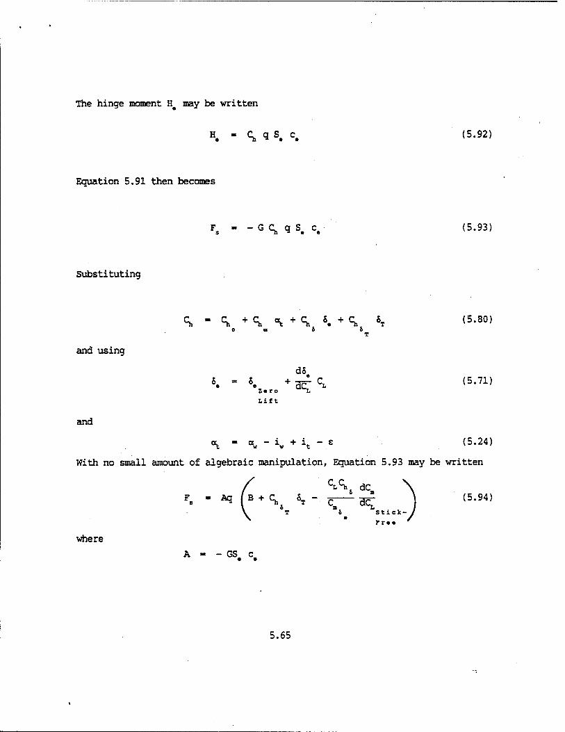
The hinge moment H# may be written
H# - q, q S, c, (5.92)
Equation 5.91 then becomes
Fs - -GC, q S. c. (5.93)
Substituting
o a o & T
and using
d6 5. - 5. + HcrCL (5-71)
Ztro I.
Lift
and
°S: " aw ~ *w + \ " c (5.24)
With no small amount of algebraic manipulation, Equation 5.93 may be written
C^. dC \ Fs - Aq (B + C, 5T - z ^ \ (5.94)
*x "i Lstick-y rr.. '
where
A - - GS# c#
5.65

0 a £ Zero Lift
Writing Equation 5.94 as a function of airspeed and substituting for
unaccelerated flight, CLq « W/S and using equivalent airspeed, V#,
Ch, dC F s
/ \ w T>6 dC 1/2 Po V2 A(B + Ch 6T)-A|^ ^ (5.95)
\ h J m L T ' 4 Stick-
rrt«
Simplifying Equation 5.95 by combining constant terms,
Fs - 1^ V 2 + Rj (5.96)
K, contains S„ which determines trim speed. K, contains dC/dC. "i » ^ LStick-
Fr ••
Equation 5.96 gives a relationship between an in-flight measurement of stick
force gradient and stick-free stability. The equation is plotted in Figure
5.37. -
5.66

PULL
FIGURE 5.37. STICK FORCE VERSUS AIRSPEED
The plot is made up of a constant force springing from.the stability term plus
a variable force proportional to the velocity squared, introduced through
constants and the tab term q 5T. Equation 5.96 introduces the interesting o T
fact that the stick-force variation with airspeed is apparently dependent on
the first term only and independent in general of the stability level. That
is, the slope of the Fs versus V is not a direct function of
dC /dC . If the derivative of Equation 5.96 is taken with respect to V, Stick-
the second term containing the stability drops out. For constant stability
level and trim tab setting, stick force gradient is a function of trim
airspeed.
dv~ Po V. A (f + \ *r) (5.97)
5.67

However, dF /dV is a function of the stability term if the trim tab
setting, S,,, is adjusted to trim at the original trim airspeed after a change
in stability level, e.g., movement of the aircraft eg. The tab setting, &T,
in Equation 5.95 should be adjusted to obtain F, - 0 at the original trim
velocity.
5T " f(VTri„. dc[ ^ (5.98)
Stick- rrtt
This new value of 6 for F§ - 0 is then substituted into Equation 5.97 so
dF. / dC
a^i. (vTri»' mi ) (5.99)
Stick- rr*t
Thus, it appears that if an aircraft is flown at two eg locations and
dF /dV is determined at the same trim speed each time, then one could s' Tlii
extrapolate or interpolate to determine the stick-free neutral point hn.
Unfortunately, if there is a significant amount of friction in' the control
system, it is impossible to precisely determine this trim speed. In order to
investigate briefly the effects of friction on the longitudinal control
system, suppose that the aircraft represented in Figure 5.38 is perfectly
trimmed at Vx i.e., (\ - S. and iT - St]. If the elevator is
used to decrease or increase airspeed with no change to the trim setting, the
friction in the control system will prevent the elevator from returning all
the way back to 6 when the controls are released. The aircraft will return
5.68
PULL
F. 0
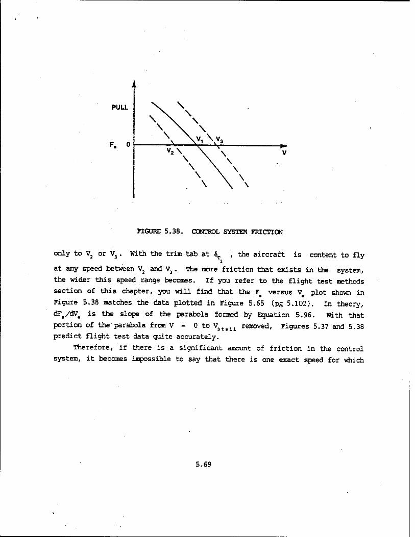
FIGURE 5.38. CONTROL SYSTEM FRICTION
only to V2 or V3. With the trim tab at $T , the aircraft is content to fly i
at any speed between V2 and V3. The more friction that exists in the system,
the wider this speed range becomes. If you refer to the flight test methods
section of this chapter, you will find that the FB versus V plot shown in
Figure 5.38 matches the data plotted in Figure 5.65 (pg 5.102). In theory,
d*",/^. is the siope of the parabola formed by Equation 5.96. With that
portion of the parabola from V ■ 0 to Vstall removed, Figures 5.37 and 5.38
predict flight test data quite accurately.
Therefore, if there is a significant amount of friction in the control
system, it becomes impossible to say that there is one exact speed for which
5.69

the aircraft is trimmed. Equation 5.99 is something less than perfect for
predicting the stick-free neutral point of an aircraft. To reduce the
undesirable effect of friction in the control system, a different approach is
made to Equation 5.94.
If Equation 5.94 is divided by the dynamic pressure, q, then,
^LSI, dC Fs/q «A (B + C, &T) - -g gc- tS. 100)
& n. L . T & Stick-
rrtt
Differentiating with respect to CL,
d(Fs/q) ^ dC,
6 Stick-
(5.101)
rrt«
or d(F /q) dCB
-ar- - f (-Tzr > (5-102) L . , stick-
mi
Trim velocity is now eliminated from consideration and the prediction of
stick-free neutral point h^ is exact. A plot of (dFs/q)/dCL versus eg
position may be extrapolated to obtain hn.
5.17 APPARENT STICK-FREE STABILITY
Speed stability or stick force gradient dFB/dV, in most cases does not
reflect the actual stick-free stability dCB/dCL of an aircraft. In Stick-
5.70

fact, this apparent stability dFg/dV, may be quite different from the actual
stability of the aircraft. Where the actual stability of the aircraft may be
marginal f dC /dC, small), or even unstable ( dCB/dCL positive), ^ B Stick- ' ^ Stick- '
r:<» Tv apparent stability of dFB/dV may be such as to make the aircraft quite
acceptable. In flight, the test pilot feels and evaluates the apparent
stability of the aircraft and not the actual stability, dCB/dCL Stick-
The apparent stability dFs/dV is affected by:
1. Changes in dCB/dCL Stick-
2. Aerodynamic balancing
3. Downsprings, bob weights, etc.
The apparent stability of the stick force gradient through a given trim
speed increases if dC /dC is made more negative. The constant K2 of Stick- Fr»«
Equation 5.96 is made more positive and in order for the stick force to
continue to pass through the desired trim speed, a more positive tab selection
is required. An aircraft operating at a given eg with a tab setting 6T is
shown in Figure 5.39, Line 1.
5.71
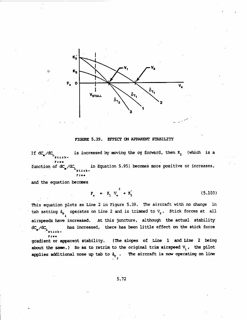
FIGURE 5.39. EFFECT CK APPARENT STABILITY
If dC /dCt Stick
function of dC /dC.
is increased by moving the eg forward, then Kj (which is a
in Equation 5.95) becomes more positive or increases, Stick-
rr«»
and the equation becomes
*i V. (5.103)
This equation plots as Line 2 in Figure 5.39. The aircraft with no change in
tab setting 5T operates on Line 2 and is trimmed to V2. Stick forces at all l
airspeeds have increased. At this juncture, although the actual stability
dC /dC has increased, there has been little effect on the stick force Stick-
rrii
gradient or apparent stability. (The slopes of Line 1 and Line 2 being
about the same.) So as to retrim to the original trim airspeed Vx, the pilot
applies additional nose up tab to ^ . The aircraft is now operating on line . 2
5.72

3. The stick force gradient through \ has increased because of an increase in the 1^ term in Equation 5.96. The apparent stability dFs/dV has increased.
Aerodynamic balancing of the control surface affects apparent stability in the same manner as eg movement. This is a design means of controlling the hinge moment coefficients, (^ and (^ . The primary reason for aerodynamic
a 4
balancing is to increase or reduce the hinge moments and, in turn, to control stick forces. Changing (^ affects the stick forces as seen in Equation 5.100.
o
In addition to the influence on hinge moments, aerodynamic balancing affects the real and apparent stability of the aircraft. Assuming that the restoring hinge moment coefficient C^ is increased by an appropriate aerodynamically
o
balanced control surface, the ratio of q, /(^ in Equation 5.87 is de-
creased.
HOL ♦£--£'.* (i-$(i-*e-) (5-87) W 11 « & Stick ru»
The combined increase in dCm/dCL and C^ , increases the K2 Stick- S
Fr*a
term in Equation 5.96 since
Ch dC K „ _AW I ■ (5.104)
"h Stick- e
r r ••
Figure 5.39 shows the effect of increased Kj. The apparent stability is not affected by the increase in Kj if the aircraft stabilizes at v2. However, once the aircraft is retrimmed to the original airspeed vt by increasing the
tab setting to ST , the apparent stability is increased. 2
5.73

5.17.1 Set-Back Hinge
Perhaps the simplest method of reducing the aerodynamic hinge moments is
to move the hinge line rearward. The hinge moment is reduced because the
moment arm between the elevator lift and the elevator hinge line is reduced.
(One may arrive at the same conclusion by arguing this part of the elevator
lift acting behind the hinge line has been reduced, while that in front of the
hinge line has been increased.) The net result is a reduction in the absolute
value of both (^ and C^ . In fact, if the hinge line is set back far enough, a 4
the sign of both derivatives can be changed. A set-back hinge is shown in
Figure 5.40.
nK X
^L.
d s=
LARGE
SMALL
FIGURE 5.40. SET-BACK HINGE
5.17.2 Overhang Balance
This method is simply a special case of set-back hinge in which the
5.74

elevator is designed so that when the leading edge protrudes into the
airstream, the local velocity is increased significantly, causing an increase
in negative pressure at that point. This negative pressure peak creates a
hinge moment which opposes the normal restoring hinge moment, reducing C . i
Figure 5.41 shows an elevator with an overhang balance.
NEGATIVE PEAK PRESSURE
HELPING MOMENT
FIGURE 5.41. OVERHANG BALANCE
5.17.3 Horn Balance
The horn balance works on the same principle as the set-back hinge; i.e.,
to reduce hinge moments by increasing the area forward of the hinge line. The
horn balance, especially the unshielded horn, is very effective in reducing
Cjj and Cjj . This arrangement shown in Figure 5.42 is also a handy way of at
improving the mass balance of the control surface.
5.75

UNSHIELDED
FIGURE 5.42. HORN BALANCE
5.17.4 Internal Balance or Internal Seal The internal seal allows the negative pressure on the upper surface and
the positive pressure on the lower surface to act on an internally sealed
surface forward of the hinge line in such a way that a helping moment is
createdV again opposing the normal hinge moments. As a result, the absolute
values of C^ and C^ are both reduced. This method is good at high indicated
airspeeds, "but is' sometimes troublesome at high Mach. Figure 5.43
shows an elevator with an internal seal.
5.76
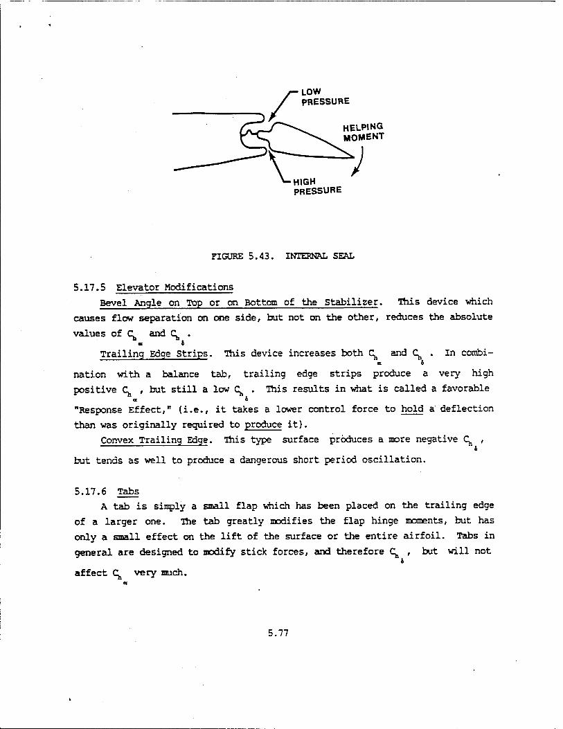
LOW PRESSURE
HELPING MOMENT
HIGH PRESSURE
FIGURE 5.43. INTERNAL SEAL
5.17.5 Elevator Modifications Bevel Angle on Top or on Bottom of the Stabilizer. This device which
causes flow separation on one side, but not on the other, reduces the absolute
values of C^ and C^ . at &
Trailing Edge Strips. This device increases both C^ and C^ . In combi-
nation with a balance tab, trailing edge strips produce a very high
positive (^ , but still a low (^ . This results in what is called a favorable a o
"Response Effect," (i.e., it takes a lower control force to hold a deflection
than was originally required to produce it).
Convex Trailing Edge. This type surface produces a more negative C^ , O
but tends as well to produce a dangerous short period oscillation.
5.17.6 Tabs
A tab is simply a small flap which has been placed on the trailing edge
of a larger one. The tab greatly modifies the flap hinge moments, but has
only a small effect on the lift of the surface or the entire airfoil. Tabs in
general are designed to modify stick forces, and therefore C^ , but will not 9
affect C^ very much.
5.77

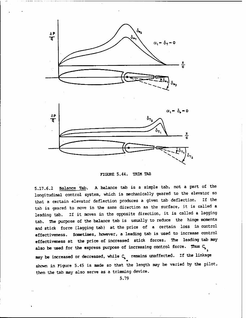
5.17.6.1 Trim Tab. A trim tab is a tab which is controlled independently of
the normal elevator control by means of a wheel or electric motor. The
purpose of the trim tab is to alter the elevator hinge moment and in doing so
drive the stick force to zero for a given flight condition. A properly
designed trim tab should be allowed to do this throughout the flight envelope
and across the allowable eg range. The trim tab reduces stick forces to zero
primarily by changing the elevator hinge moment at the elevator deflection
required for trim. This is illustrated in Figure 5.44.
5.78
c
^-iM «T.
FIGURE 5.44. TRIM TAB
5.17.6.2 Balance Tab. A balance tab is a single tab, not a part of the
longitudinal control system, which is mechanically geared to the elevator so
that a certain elevator deflection produces a given tab deflection. If the
tab is geared to move in the same direction as the surface, it is called a
leading tab. If it moves in the opposite direction, it is called a lagging
tab. The purpose of the balance tab is usually to reduce the hinge moments
and stick force (lagging tab) at the price of a certain loss in control
effectiveness. Sometimes, however, a leading tab is used to increase control
effectiveness at the price of increased stick forces. The leading tab may
also be used for the express purpose of increasing control force. Thus (^ o
may be increased or decreased, while (^ remains unaffected. If the linkage a
shown in Figure 5.45 is made so that the length may be varied by the pilot,
then the tab may also serve as a trimming device.
5.79

LAGGING TAB
FIGURE 5.45. BALANCE TAB
5.17.6.3 Servo or Control Tab. The servo tab is linked directly to the
aircraft longitudinal control system in such a manner that the pilot moves the
tab and^the tab moves the elevator, which is free to float. The summation of
elevator hinge moment due to elevator deflection just balances out the hinge
moments due to c^. and 6T. The stick forces are now a function of the tab
hinge moment or C^ . Again C^ is not affected. e « T
5.17.6.4 Spring Tab. A spring tab is a lagging balance tab which is geared
in such a way that the pilot receives the most help from the tab at high
speeds where he needs it the most; i.e., the gearing is a function of dynamic
pressure. The spring tab is shown in Figure 5.46.
5.80

HINGE OF FREE ARM
FIGURE 5.46. SPRING TAB
The basic principles of its operation are:
1. An increase in dynamic pressure causes an increase in hinge moment and stick force for a given control deflection.
2. The increased stick force causes an increased spring deflection and, therefore, an increased tab deflection.
3. The increased tab deflection causes a decrease in stick force. Thus an increased proportion of the hinge moment is taken by the tab.
4. Therefore, the spring tab is a geared balance tab where the gearing is a function of dynamic pressure.
5. Thus, the stick forces are more nearly constant over the speed range of the aircraft. That is, the stick force required to produce a given deflection at 300 knots is still greater than at 150 knots, but not by as much as before. Note that the pilot cannot tell what is causing the forces he feels at the stick. This appears to change "speed stability," but in fact changes actual stability or dc./aq,.
6. After reaching full spring or tab deflection the balancing feature is lost and the pilot must supply the full force necessary for further deflection. (This acts as a safety feature.)
5.81
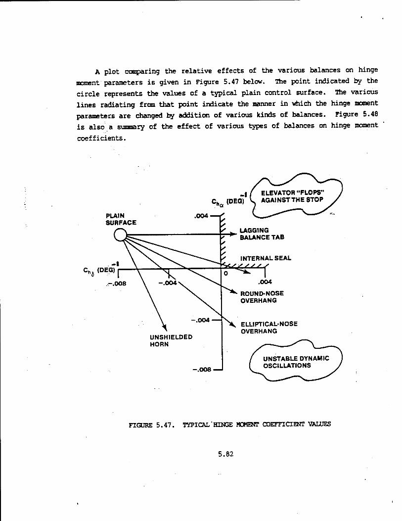
A plot comparing the relative effects of the various balances on hinge
moment parameters is given in Figure 5.47 below. The point indicated by the
circle represents the values of a typical plain control surface. The various
lines radiating from that point indicate the manner in which the hinge moment
parameters are changed by addition of various kinds of balances. Figure 5.48
is also a summary of the effect of various types of balances on hinge moment
coefficients.
_f / ELEVATOR "FLOPS' Ch (DEQ) S AGAINST THE STOP
PLAIN SURFACE
004
f ^ LAGGING 7~^" BALANCE TAB
INTERNAL SEAL
C„5 (DEG) ^e^f .004
UNSHIELDED HORN
ROUND-NOSE OVERHANG
ELLIPTICAL-NOSE OVERHANG
-.008
FIGURE 5.47. TYPICAL'HINGE MOMENT COEFFICIENT VALUES
5.82

NOMENCLATURE
SET-BACK HINGE
SIGN NORMALLY (+)
REDUCED
SIGN ALWAYS (-)
REDUCED
OVERHANG REDUCED REDUCED les, UNSHIELDED HORN REDUCED REDUCED TOP
VIEW
INTERNALSEAL REDUCED REDUCED 1G>
BEVEL ANGLE STRIPS REDUCED REDUCED 4t *
TRAILING EDGE STRIPS INCREASED INCREASED
CONVEX TRAILING EDGE NO CHANGE INCREASED K
TABS NO CHANGE INCREASED
OR DECREASED
Id^"' INCREASED
DECREASED
LAGGING BALANCE TAB NO CHANGE DECREASED lO =©-
LEADING BALANCE TAB NO CHANGE INCREASED ^
t
BLOW DOWN TAB OR SPRING TAB
NO CHANGE INCREASED, DECREASES
WITH "q" &
FIGURE 5.48. METHODS OF CHANGINS AERODYNAMIC HINGE MOMENT COEFFICIENT MAGNITUDES (TAIL-TO-THE-REAR AIRCRAFT)
5.83
In summary, aerodynamic balancing is "tailoring" the values of
of C and (^ during the aircraft design phase in order to increase or
decrease hinge moments. It is a method of controlling stick forces and
affects the real and apparent stability of the aircraft. In the literature,
dynamic control balancing is often defined as making C^ small or just
slightly positive. Note from Figure 5.47 that the addition of an unshielded
horn balance changes C. without affecting C^ very much. If c; is made
exactly zero, the aircraft's stick-fixed and stick-free stability are
the same. Making C^ negative is defined as overbalancing. If q is made slightly
negative, then the aircraft is more stable stick-free than stick-fixed. Early
British flying quality specifications permitted an aircraft to be unstable
stick-fixed as long as stick-free stability was maintained. Overbalancing
increases stick forces. Because of the very low force gradients in most modern aircraft at the
aft center of gravity, improvements in stick-free longitudinal stability are
obtained by devices which produce a constant pull force on the stick
independent of airspeed which allows a more noseup tab setting and steeper
stick force gradients. Two devices for increasing the stick force gradients
are the downspring and bobweight. Both effectively increase the apparent
stability of the aircraft.
5.17.7 Downspring A virtually constant stick force may be incorporated into the control
system by using a downspring or bungee which tends to pull the top of the
stick forward. From Figure 5.49 the force required to counteract the spring
is
F - Ti - K3 (5.106) "Downspring 2 Downspring
If the spring is a long one, the tension in it will be increased only slightly
as the top moves rearward and can be considered to be constant.
The equation with the downspring in the control system becomes,
5.84

h< + K»+ h (5.107) Dowaapring
As shown in Figure 5.39, the apparent stability will increase when the
aircraft is once again retrimmed by increasing the tab setting. Note that the
downspring increases apparent stability, but does not affect the actual
; no change to Kj). stability of the aircraft (dCB/dCL Stick-
rt«i
&T
TTAO
U
k
-►F.
"/"' TENSIONS CONSTANT = T I » -MmwewnmmetjtJWMs- <j-
0.
FIGURE 5.49. DOWNSPRING
5.17.8 Bobweight
Another «ethod of introducing a nearly constant stick force is by placing
a bobweight in the control system which causes a constant moment (Figure
5.50). The force to counteract the bobweight is,
-. nW Bobw»ight \
(5.108)
5.85

Like the downspring, the bobweight increases the stick force throughout the
airspeed range and, at increased tab settings, the apparent stability or stick
force gradient. The bobweight has no effect on the actual stability of the
aircraft fdC /dC ^ • V Stick-'
rtti
TTA
1 1
nW
T-H-F.
^h7TTTr
FIGURE 5.50. BOBWEIGHT
A spring may be used as an "upspring," and a bobweight nay be placed on the
opposite side of the stick in the control system. Those configurations are
illustrated in Figure 5.51. In this configuration, the stick force would be
decreased, and the apparent stability also decreased. It should again be
emphasized that regardless of spring or bobweight configuration, there is no
effect on the actual stability (dC/dC^ j of the aircraft. * Stick-'
rrti
Further use of these control system devices will be discussed in Chapter 6,
Maneuvering Flight.
5.86
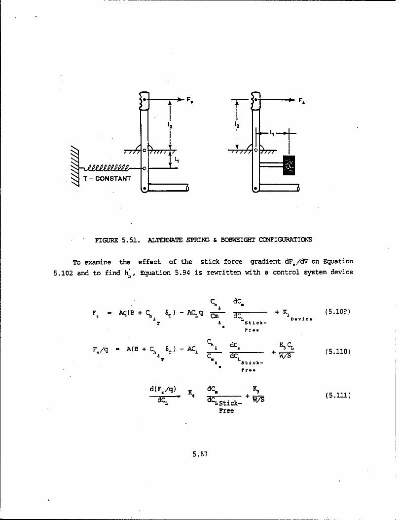
TT£
^r-Jimmmir- T = CONSTANT
T-^F.
T77TT
r§ -Art
-►F.
Ir H—«■
W
FIGURE 5.51. ALTERNATE SPRING & BOBWEIGHT C0NFIGURATIC3NS
To examine the effect of the stick force gradient dFs/dV on Equation
5.102 and to find h' , Equation 5.94 is rewritten with a control system device
Ch dC. Fs - AqCB + q 6T) -ACLq ^- ^
b 1* T &
*3 (5.109)
Stick-
rrtt
Dtvic«
Fs/q « A(B + Ch 6T) --L AC. \ dC- BcT
5£ w/s Stick-
rra«
(5.110)
d(F,/q) K dC, -v 4
^T~ *£ Stick- Free
W/S (5.111)
5.87
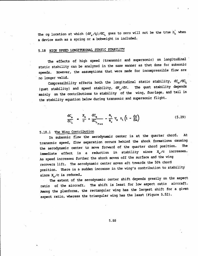
when The eg location at which (dFs/q)/dCL goes to zero will not be the true h
a device such as a spring or a bobweight is included.
5.18 HIGH SPEED LONGITUDINAL STATIC STABILITY
The effects of high speed (transonic and supersonic) on longitudinal
static stability can be analyzed in the same manner as that done for subsonic
speeds. However, the assumptions that were made for incompressible flow are
no longer valid. Compressibility effects both the longitudinal static stability, dCB/dCL
(gust stability) and speed stability, dFs/dV. The gust stability depends
mainly on the contributions to stability of the wing, fuselage, and tail in
the stability equation below during transonic and supersonic flight.
*> . £ + £_-£v„^-£) aCT - —L
Fus
5.18.1 The Wing Contribution in subsonic flow the aerodynamic center is at the quarter chord. At
transonic speed, flow separation occurs behind the shock formations causing
the aerodynamic center to move forward of the quarter chord position. The
immediate effect is a reduction in stability since X/c increases.
As speed increases further the shock moves off the surface and the wing
recovers lift. The aerodynamic center moves aft towards the 50% chord
position. There is a sudden increase in the wing's contribution to stability
since X/c is reduced. The extent of the aerodynamic center shift depends greatly on the aspect
ratio of the aircraft. The shift is least for low aspect ratio aircraft.
Among the planforms, the rectangular wing has the largest shift for a given
aspect ratio, whereas the triangular wing has the least (Figure 5.52).
5.88

c
^-AAR-2^/\
.6
AR = 4_ 1 1 .4
V
// N^-AR = 2
.2 i l 0
1 2
MACH
FIGURE 5.52. AC VARIATION WITH MACH
5.18.2 The Fuselage Contribution in supersonic flow, the fuselage center of pressure moves forward causing
a positive increase in the fuselage dC./dCL or a destabilizing influence on
the fuselage term. Variation with Mach is usually small and will be
ignored. •
5.18.3 The Tail Contribution
The tail contribution to stability depends on the variation of lift curve slopes, a and at, plus downwash e with Mach during transonic and supersonic
flight. It is expressed as:
5.89

(-at/a„) VH r^ (1 - de/do)
During subsonic flight at/aw remains approximately constant. The slope
of the lift curve, aw varies as shown in Figure 5.53. This variation of a in
the transonic speed range is a function of geometry (i.e., aspect ratio,
thickness, camber, and sweep). at varies in a similar manner. Limiting
further discussion to aircraft designed for transonic flight or aircraft which
employ airfoil shapes..with small thickness to chord ratios, then aw and a
increase slightly in the transonic regime. For all airfoil shapes, the values
of aw and at decrease as the airspeed increases supersonically.
12.0
8.0
(RAD"1)
4.0
RECTANGULAR WING
DELTA WING
FIGURE 5.53. LIFT CURVE SLOPE VARIATION WITH MACH
5.90
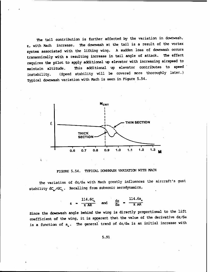
The tail contribution is further affected by the variation in downwash,
e, with Mach increase. The downwash at the tail is a result of the vortex
system associated with the lifting wing. A sudden loss of downwash occurs
transonically with a resulting increase in tail angle of attack. The effect
requires the pilot to apply additional up elevator with increasing airspeed to
maintain altitude. This additional up elevator contributes to speed
instability. (Speed stability will be covered more thoroughly later.)
Typical downwash variation with Mach is seen in Figure 5.54.
THIN SECTION
FIGURE 5.54. TYPICAL DOWNWASH VARIATION WITH MACH
The variation of de/d« with Mach greatly influences the aircraft's gust
stability dC /dCL. Recalling from subsonic aerodynamics,
e - 114.6^
It AR and de
114.6aw
n~ÄR~
Since the downwash angle behind the wing is directly proportional to the lift
coefficient of the wing, it is apparent that the value of the derivative de/da
is a function of aw. The general trend of ds/da is an initial increase with
5.91

Mach starting at subsonic speeds. Above Mach 1.0, de/da decreases and
approaches zero. This variation depends on the particular wing geometry of
the aircraft. As shown in Figure 5.55, de/da may dip for thicker wing
sections where considerable flow separation occurs. Again, de/da is very much
dependent upon a.
0.8
de_ da
0.4
■ STRAIGHT i TAPERED PLANFORM
DELTA PLANFORM
3.0
FIGURE 5.55. DOHNWASH DERIVATIVE VS MACH
For an aircraft designed for high speed flight, the variation of de/da
with increasing Mach results in a slight destabilizing effect in the transonic
regime and contributes to increased stability in the supersonic speed regime;
therefore, the overall tail contribution to stability is difficult to predict.
5.92

A loss of stabilizer effectiveness is experienced in supersonic flight as
it becomes a less efficient lifting surface. The elevator power, C ,
increases as airspeed approaches Mach 1 . Beyond Mach 1, elevator
effectiveness <
in Figure 5.56.
effectiveness decreases. Typical variations in Ca with Mach are shown 6
ONE PIECE HORIZONTAL TAIL
"*.
-c„
TYPICAL SWEPT WING
FIGURE 5.56. MACH VARIATIONS ON C AND C
5.93

The overall effect of transonic and supersonic flight on gust stability or dC /dCt is also shown in Figure 5.56. Static longitudinal stability increases'supersonically. The speed stability of the aircraft is affected as veil. The pitching moment coefficient equation developed in Chapter 4 can be written,
C--C^c| + C TT+C^+C k ,5-112) m» *n, ^^o *Vüo a.2U° <J
Assuming no pitch rates, Equation 5.112 can be written
C - C &+C TT + C ö (5.113)
All three of the stability derivatives in
Equation 5.113 are functions of Mach. The elevator deflection required to
trim as an aircraft accelerates from subsonic to supersonic flight depends on
how these derivatives vary with Mach. For supersonic aircraft, speed
stability is provided entirely by the artificial feel system. However, it
usually depends on how S. varies with Mach. A reversal of elevator deflection
with increasing airspeed usually requires a relaxation of forward pressure or
even a pull force to maintain altitude or prevent a nose down pitch tendency.
Elevator deflection versus Mach curves for several supersonic aircraft
are shown in Figure 5.57. The important point from this figure is that
supersonically dS /dCL is no longer a valid indication of gust stability. All
of the aircraft "shown in Figure 5.57 are more stable supersonically than
subsonically, if you were to look purely at neutral points or values of the
stability derivative CB .
5.94

MACH
0.6 0.8
'FIGURE 5.57. STABILIZER DEFLECTION VS MACH FOR SEVERAL SUPERSONIC AIRCRAFT
Whether the speed instability or reversal in elevator deflections and
stick forces are objectionable depends on many factors such as magnitude of
variation, length of time required to transverse the region of instability,
control system characteristics, and conditions of flight.
In the F-100C, a pull of 14 pounds was required when accelerating from
Mach 0.87 to 1.0. The test pilot described this trim change as disconcerting
while attempting to maneuver the aircraft in this region and recommended that
a "q" or Mach sensing device be installed to eliminate this characteristic.
Consequently, a mechanism was incorporated to automatically change the
artificial feel gradient as the aircraft accelerates through the transonic
range. Also, the longitudinal trim is automatically changed in this region by
the use of a "Mach Trimmer."
5.95

F-104 test pilots stated that F-104 transonic trim changes required an
aft stick movement with increasing speed and a forward stick movement when
decreasing speed but described this speed instability as acceptable.
F-106 pilots stated that the Mach 1.0 to 1.1 region is characterized by a
moderate trim change to avoid large variations in altitude during
accelerations. Minor speed instabilities were not unsatisfactory.
T-38 test pilots described the transonic trim change as being hardly
perceptible. Aircraft design considerations are influenced by the stability aspects of
high speed flight. It is desirable to design an aircraft where trim changes
through transonic speeds are small. A tapered wing without camber, twist, or
incidence or a low aspect ratio wing and tail provide values of Xv/c, aw,
at, and de/da which vary minimally with Mach. An all-moving tail (slab)
gives negligible variation of CB with Mach and maximum control effec- o
tiveness. A full power, irreversible control system is necessary to counter-
act the erratic changes in pressure distribution which affect C^ and C^.
5.19 LONGITUDINAL STATIC STABILITY FLIGHT TESTS
The purpose of these flight tests is to determine the longitudinal static
stability characteristics of an aircraft. These characteristics include gust
stability, speed stability, and friction/breakout. Trim change tests will
also be discussed. An aircraft is said to be statically stable longitudinally (positive gust
stability) if the moments created when the aircraft is disturbed from trimmed
flight tend to return the aircraft to the condition from which it was
disturbed. Longitudinal stability theory shows the flight test relationships
for stick-fixed and stick-free gust stability, d^/dq, to be
5.96

stick-fixed: -&r- - - ■=- -& (5.69)
uo 1 dC.
c, dCl 0
1
'stick rix.d
d(Fs/q) m -A\ c
dC m
dC, Stick
stick-free: -»/M - -A *_ _» (5.101)
rtM
Stick force (Fs), elevator deflection (S#), equivalent velocity (V#) and
gross weight (W) are the parameters measured to solve the above equations.
When dS /dC is zero, an aircraft has neutral stick-fixed longitudinal static
stability. As d5#/dCL increases, the stability of the aircraft increases.
The same statements about stick-free longitudinal static stability can be made
with respect to d(F /q)/dCL. The neutral point is the eg location which
gives neutral stability, stick-fixed or stick-free. These neutral points are
determined by flight testing at two or more eg locations, and extrapolating
the curves of dS#/dCL and d(Fs/q)/dCL versus eg to zero.
The neutral point so determined is valid for the trim altitude and
airspeed at which the data were taken and may vary considerably at other trim
conditions. A typical variation of neutral point with Mach is shown in Figure
5.63.
5.97
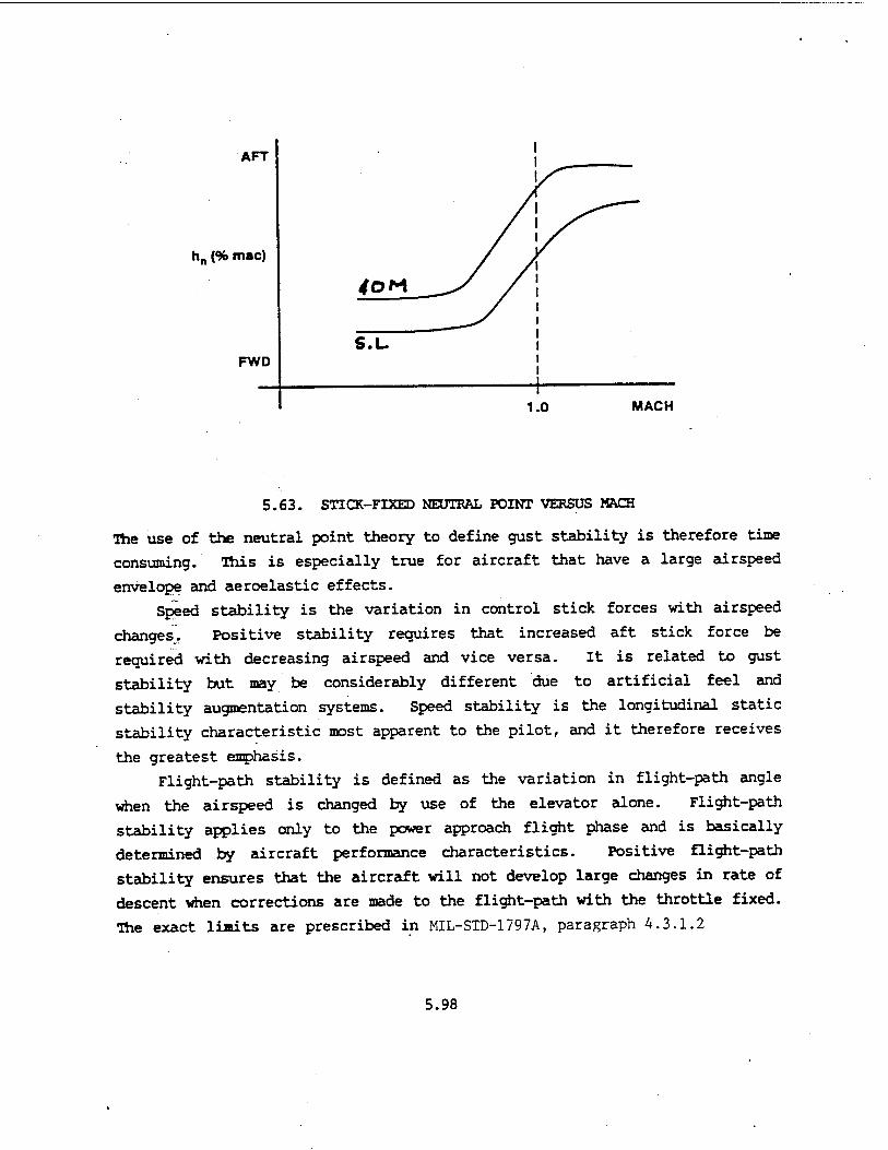
AFT
hn (9b mac)
FWD
1.0 MACH
5.63. STICK-FIXED NEUTRAL POINT VERSUS MACH
The use of the neutral point theory to define gust stability is therefore time
consuming. This is especially true for aircraft that have a large airspeed
envelope and aeroelastic effects.
Speed stability is the variation in control stick forces with airspeed
changes. Positive stability requires that increased aft stick force be
required with decreasing airspeed and vice versa. It is related to gust
stability but may be considerably different due to artificial feel and
stability augmentation systems. Speed stability is the longitudinal static
stability characteristic most apparent to the pilot, and it therefore receives
the greatest emphasis.
Flight-path stability is defined as the variation in flight-path angle
when the airspeed is changed by use of the elevator alone. Flight-path
stability applies only to the power approach flight phase and is basically
determined by aircraft performance characteristics. Positive flight-path
stability ensures that the aircraft will not develop large changes in rate of
descent when corrections are made to the flight-path with the throttle fixed.
The exact limts are prescribed in MIL-STD-1797A, paragraph A.3.1.2
5.98

An aircraft likely to encounter difficulty in meeting these limits would be
one whose power approach airspeed was far up on the "backside" of the power
required curve. A corrective action might be to increase the power approach
airspeed, thereby placing it on a flatter portion of the curve or by
installing an automatic throttle.
5.19.1 Military Specification Requirements The iyi>4 version of MIL-F-8785, the specification which preceeded the
current MIL-STD-1797A, established longitudinal stability requirements in terms of neutral point. This criteria is still valid for testing aircraft with reversible control systems, and many aircraft with irreversible control systems which are not highly augmented. MIL-STD-1797A is not written in terms of neutral point. Instead, section A.4.1 specifies longitudinal stability with respect to speed and
pitch attitude. The requirements of this section are relaxed in the transonic
speed range except for those aircraft which are designed for prolonged
transonic operation. As technology progresses, highly augmented aircraft and
aircraft with fly-by-wire control systems may be designed with neutral speed
stability. The F-15, F-16, and F-20 are examples of aircraft with neutral
speed stability. For these aircraft, the program manager may require a mil
spec written specifically for the aircraft and control system involved.
5.19.2 Flight Test Methods
There are two general test methods (stabilized and acceleration/
deceleration) used to determine either speed stability or neutral points.
5.19.2.1 Stabilized Method. This method is used for aircraft with a small
airspeed range in the cruise flight phase and virtually all aircraft in the
power approach, landing or takeoff flight phases. Propeller type aircraft are
normally tested by this method because of the effects on the elevator control
power caused by thrust changes. It involves data taken at stabilized
airspeeds at the trim throttle setting with the airspeed maintained constant
by a rate of descent or climb. As long as the altitude does not vary
excessively (typically + 1,000 ft) this method gives good results, but it is
time consuming.
5.99

The aircraft is trimmed carefully at the desired altitude and airspeed,
and a trim shot is recorded. Without moving the throttle or trim setting, the
pilot changes aircraft pitch attitude to achieve a lower or higher airspeed
(typically in increments of ± 10 knots) and maintains that airspeed.
Aircraft with both reversible and irreversible hydro-mechanical control
systems exhibit varying degrees of friction and breakout force about trim,
the breakout force is the force required to begin a tiny movement of the
stick. ' This initial movement will not cause an aircraft motion as observed on
the windscreen. The friction force is that additional amount of pilot-applied
force required to produce the first tiny movement of the elevator. These
small forces, friction and breakout, combine to form what is generally termed
the "friction band." Since the pilot has usually moved the control stick fore and aft through
the friction band, he must determine which side of the friction band he is on
before recording the test point data. The elevator position for this airspeed
will not vary, but stick force varies relative to the instantaneous position
within the friction band at the time the data is taken. Therefore, the pilot
should (assuming an initial reduction in airspeed from the trim condition)
increase force carefully until the nose starts to rise. The stick should be
frozen • at this point (where any increase in stick force will result m
elevator movement and thus nose rise) and data recorded. The same technique
should be used for all other airspeed points below trim. For airspeed above
trim airspeed, the same technique is used although now the stick is frozen at
a point where any increase in push force will result in nose drop.
5 19 2.2 Acceleration/Deceleration Method. This method is commonly used for
aircraft that have a large airspeed envelope. It is always used for transonic
testing. It is less time consuming than the stabilized method but introduces
thrust effects. The U.S. Navy uses the acceleration/deceleration method but
maintains the throttle setting constant and varies altitude to change
airspeed. The Navy method minimizes thrust effects but introduces altitude
effects.
5.100

The sense trim shot is token as in the stabilized method to establish trim
conditions. MIL-STD-1797Ärequires that the aircraft exhibit positive speed
stability only within ±50 knots or ±15 percent of the trim airspeed, whichever
is the less. This requires very little power change to traverse this band and
maintain level flight unless the trim airspeed is near the back side of the
thrust required curve. Before the 1968 revision to MIL-F-8785, the flight
test technique commonly used to get acceleration/deceleration data was full
military power or idle, covering the entire airspeed envelope. Unfortunately,
this technique cannot be used to determine the requirements under the current
standard with the non-linearities that usually exist in the control system.
Therefore a series of trim points must be selected to cover the envelope with
a typical plot (friction and breakout excluded) shown in Figure 5.64.
TEST ALTITUDE
SERVICE ENVELOPE
FIGURE 5.64. SPEED STABILITY DATA
5.101
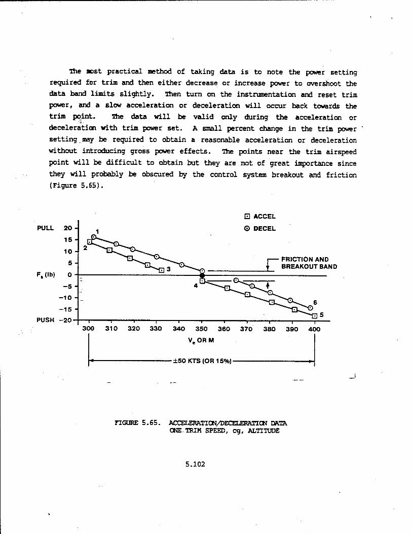
The aost practical method of taking data is to note the power setting
required for trim and then either decrease or increase power to overshoot the
data band limits slightly. Then turn on the instrumentation and reset trim
power, and a slow acceleration or deceleration will occur back towards the
trim point. The data will be valid only during the acceleration or
deceleration with trim power set. A small percent change in the trim power
setting, may be required to obtain a reasonable acceleration or deceleration
without introducing gross power effects. The points near the trim airspeed
point will be difficult to obtain but they are not of great importance since
they will probably be obscured by the control system breakout and friction
(Figure 5.65).
PULL
F,(lb)
PUSH -:
□ ACCEL
© DECEL
FRICTION AND BREAKOUT BAND
nGURE 5.65. ACrFT.KRATION/DErTT.KRATION DATA ONE.TRIM SPEED, eg, ALTITUDE
5.102

Throughout the acceleration or deceleration, the primary parameter to
control is stick force. It is important that the friction band not be
reversed during the test run. A slight change in altitude is preferable
(i.e. to let the aircraft climb slightly throughout an acceleration) to avoid
the tendency to reverse the stick force by over-rotating the nose. The
opposite is advisable during the deceleration.
There is a relaxation in the requirement for speed stability in the
transonic area unless the aircraft is designed for continued transonic
operation. The best way to define where the transonic range occurs is to
determine the point where the Fs versus V goes unstable. In this area,
MIL-STD-1797A allows a specified maximum instability. The purpose of the
transonic longitudinal static stability flight test in the transonic area is
to determine the degree of instability.
The transonic area flight test begins with a trim shot at some high
subsonic airspeed. The power is increased to maximum thrust and an
acceleration is begun.
It is important that a stable gradient be established before entering the
transonic area. Once the first sensation of instability is felt by the pilot,
his primary control parameter changes from stick force to attitude. From this
point until the aircraft is supersonic, the true altitude should be held as
closely as possible. This is because the unstable stick force being measured
will be in error if a climb or descent occurs. A radar altimeter output on an
over-water flight or keeping a flight path on the horizon are precise ways to
hold constant altitude, but.if'these are not available, the pilot will have to
use the outside references to maintain level flight.
Once the aircraft goes supersonic, the test pilot should again concern
himself with not reversing the friction band and with establishing a stable
gradient. The acceleration should be continued to the limit of the service
envelope to test for supersonic speed stability. The supersonic data will
also have to be shown at ±15% of the trim airspeed, so several trim shots may
be required. A deceleration from VMX to subsonic speed should be made with a
careful reduction in power to decelerate supersonically and transonically.
The criteria for decelerating through the transonic region are the same as for
5.103

the acceleration. Power reductions during this deceleration will have to be
done carefully to minimize thrust effects and still decelerate past the Mach
drag rise point to a stable subsonic gradient.
5.19.3 Fli^it-Path Stability
Flight-path stability is a criterion applied to power approach and
landing qualities. It is primarily determined by the performance
characteristics of the aircraft and related to stability and control only
because it places another requirement on handling qualities. The following is
one way to look at flight-path stability. Thrust required curves are shown
for two aircraft with the recommended final approach speed marked in Figure
5.66.
o Ul cc 5 o ui cc f- w CC X
A~
Vom,„<PA>
FIGURE 5.66. THRUST REQUIRED VS VELOCITY (TWO AIRCRAFT)
5.104
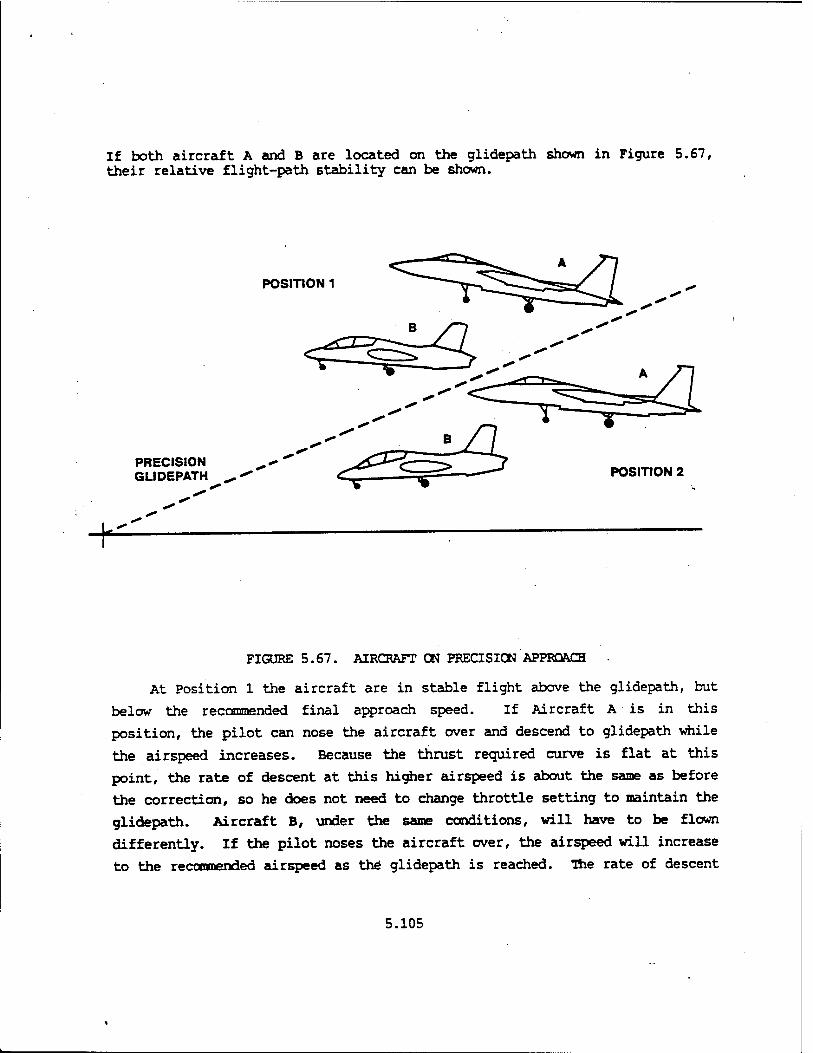
If both aircraft A and B are located on the glidepath shown in Figure 5.67, their relative flight-path stability can be shown.
POSITION 1
PRECISION GLIDEPATH POSITION 2
¥
FIGURE 5.67. AIRCRAFT ON PRECISION APPROACH
At Position 1 the aircraft are in stable flight above the glidepath, but
below the recommended final approach speed. If Aircraft A is in this
position, the pilot can nose the aircraft over and descend to glidepath while
the airspeed increases. Because the thrust required curve is flat at this
point, the rate of descent at this higher airspeed is about the same as before
the correction, so he does not need to change throttle setting to maintain the
glidepath. Aircraft B, under the same conditions, will have to be flown
differently. If the pilot noses the aircraft over, the airspeed will increase
to the recommended airspeed as the" glidepath is reached. The rate of descent
5.105

at this power setting is less than it was before so the pilot will go above
glidepath if he maintains this airspeed. At Position 2 the aircraft are in stable flight below the glidepath but
above the recommended airspeed. Aircraft A can be pulled up to the glidepath
and maintained on the glidepath with little or no throttle change. Aircraft B
will develop a greater rate of descent once the airspeed decreases while
coming up to glidepath and will fall below the glidepath again.
If the aircraft are in Position 1 with the airspeed higher than
recommended instead of lower, the same situation will develop when correcting
back to flight-path, but the required pilot compensation is increased. In all
cases Aircraft A has better flight-path stability than Aircraft B. As
mentioned earlier in this chapter, aircraft which have unsatisfactory
flight-path stability can be improved by increasing the recommended final
approach airspeed or by adding an automatic throttle.
Another way of looking at flight-path stability is by investigating the
difficulty that a pilot has in maintaining glidepath even when using the
throttles. This problem is seen in large aircraft for which the time lag in
pitching the aircraft to a new pitch attitude is quite long. In these
instances, incorporation of direct lift allows the pilot to correct the
glidepath without pitching the aircraft. Direct lift control will also affect
the influence of performance on flight-path stability.
5.19.4 Trim Change Tests The purpose of this test is to determine the control- force changes associated
with normal configuration changes, trim system failure, or transfer to
alternate control systems in relation to specified limits. It must also be
determined that no undesirable flight characteristics accompany these
configuration changes. Pitching moments on aircraft are normally associated
with changes in the condition of any of the following: landing gear, flaps,
speed brakes, power, bomb bay doors, rocket and missile doors, or any
jettisonable device. The magnitude of the change in control forces resulting
from these pitching moments is limited by MIL-STD-1797A, and it is the
responsibility of the testing organization to determine if the actual forces
are within the specified limits.
5.106

The pitching moment resulting from a given configuration change will
normally vary with airspeed, altitude, eg loading, and initial configuration
of the aircraft. The control forces resulting from the pitching moment will
further depend on the aircraft parameters being held constant during the
configuration change. These factors should be kept in mind when determining
the conditions under which the given configuration change should be tested.
Even though the specification lists the altitude, airspeed, initial
conditions, and parameter to be held constant for most configuration changes,
some variations may be necessary on a specific aircraft to provide information
on the most adverse conditions encountered in operational use of the aircraft.
The altitude and airspeed should be selected as indicated in the specifica-
tions or for the most adverse conditions. In general, the trim change will be
greatest at the highest airspeed and the lowest altitude. The effect of eg
location is not so readily apparent and usually has a different effect for
each configuration change. A forward loading may cause the greatest trim
change for one configuration change, and an aft loading may be most severe for
another, using the build up approach, a mid eg loading is normally selected
since rapid movement of the eg in flight will probably not be possible. If a
specific trim change appears marginal at this loading, it may be necessary to
test it at other eg loadings to determine its acceptability.
Selection of the initial aircraft configurations will depend on the
anticipated normal operational use of the aircraft. The conditions given in
the specifications will normally be sufficient and can always be used as a
guide, but again variations may be necessary for specific aircraft. The same
holds true for selection of the aircraft parameter to hold constant during the
change. The parameter that the pilot would normally want to hold constant in
operational use of the aircraft is the one that should be selected.
Therefore, if the requirements of MIL-STD-1797A do not appear logical or
complete, then a more appropriate test should be added or substituted.
In addition to the conditions outlined above, it may be necessary to test
for some configuration changes that could logically be accomplished
5.107

simultaneously. The force changes might be additive and could be objection-
ably large. For example, on a go-around, power may be applied and the landing
gear retracted at the same time. If the trim changes associated with each
configuration change are appreciable and in the same direction, the combined
changes should definitely be investigated. The specifications require that no
objectionable buffet or undesirable flight chracteristics be associated with
normal trim changes. Some buffet is normal with some configuration changes,
e.g., gear extension, however, it would be considered if this buffet tended to
mask the buffet associated with stall warning. The input of the pilot is the
best measure of what actually constitutes "objectionable," but anything that
would interfere with normal use of the aircraft would be considered objection-
able. The same is true for "undesirable flight characteristics." An example
would be a strong nose-down pitching moment associated with gear or flap
retraction after take-off.
The standard also sets limits on the trim changes resulting from transfer
to an alternate control system. The limits vary with the type of alternate
system and the configuration and speed at the time of transfer but in no case
may a dangerous flight condition result. A good example of this is the
transfer to manual reversion in the A-10. It will probably be necessary for
the pilot to study the operation of the control system and methods of
effecting transfer in order to determine the conditions most likely to cause
an unacceptable trim change upon transferring from one system to the other.
As in all flight testing, a thorough knowledge of the aircraft and the
objectives of the test will improve the quality and increase the value of the
test results.
5.108

PROBLEMS
5.1 In Subsonic Aerodynamics the following approximation was developed for
the Balance Equation
C„ - C + CL (eg - ac) + CB "eg "ac L tail
where C is the total stability contribution of the tail. "tail
(a) Sketch the location of the forces, moments, and eg required to
balance an airplane using the above equation.
(b) Using the data shown below, what contribution is required from the
tail to balance the airplane?
C - -0.12 Cn - ? tail .
ac - 0.25 (25%) CL - 0.5
eg - 0.188 (18.8%)
(c) If this airplane were a fixed hang-glider and a CL - 1.3 were
required to flare and land, how far aft must the eg be shifted to
obtain the landing CL without changing the tail contribution?
(d) If a 4% margin were desired between max aft eg and the aerodynamic
center for safety considerations, how much will the tail
contribution have to increase for the landing problem presented in
(c)?
(e) List four ways of increasing the tail contribution to stability.
5.109

5.2 Given the aircraft configurations shown below, write the Balance and
Stability Equations for the thrust contributions to stability. Sketch the
forces involved and state which effects are stabilizing and which are
destabilizing.
(a) DC-10
(b) Britten-Norman Trislander
5.3 (a) Are the two expressions below derived for the tail-to-the-rear
aircraft valid for the canard aircraft configuration?
HC: c? h - h
Static margin ■ h - h
5.110

(b) Derive an expression for elevator power for the canard aircraft
configuration. Determine its sign.
(c) What is the expression for elevator effectiveness for the canard
aircraft configuration? Determine its sign.
5.4 During wind tunnel testing, the following data were recorded:
Ci. 5 (Steg)
S (Seg)
6 (äeg)
h - 0.20 h - 0.25 h - 0.30
0.2 -2 -3 -4
0.6 4 1 -2
1.0 10 5 0
Elevator limits are + 20°
A. Find the stick-fixed static margin for h = 0.20
Find the numerical value for elevator power. B.
C. Find the most forward eg permissible if it is desired to be able to
stabilize out of ground effect at a C Ljnax
1.0.
5.5 Given the flight test data below from the aircraft which was wind tunnel
tested in Problem 5.4, answer the following questions:
5.111
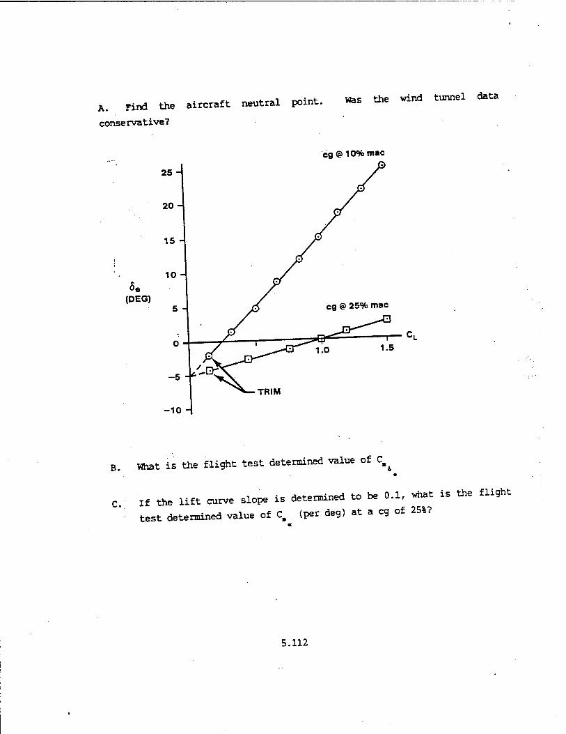
A. Find the ai
conservative?
rcraft neutral point. Was the wind tunnel data
eg @ 10% mac
25 -
20-
(DEG}
TRIM
- C,
B. What is the flight test determined value of C^
C If the lift curve slope is determined to be 0.1, vhat is the flight
test determined value of C, (per deg) at a eg of 25%?
5.112

5.6 Given geometric data for the canard design in Problem 5.5, calculate an
estimate for elevator power.
HINT: Assume:
- °* VH n, HT a^ ■ a ■ wind tunnel value
l\ - 1.0
Given:
Slab canard
1, - 14ft
ST «. 10ft2
c - 7ft
S - 200ft2
5.7 The Forward Swept Wing (FWS) technology aircraft designed by North
American is shown below. The aerodynamic load is shared by the two
"wings" with the forward wing designed to carry about 30% of the
aircraft weight. For this design condition, answer the following
multiple choice questions by circling the number of correct answer(s).
! RW
5.113

A. At the eg location marked FWD the aircraft:
(1) Can be balanced and is stable.
(2) Can be balanced and is stable only if the eg is ahead of the neutral
point.
(3) Can be balanced and is unstable.
(4) Cannot be balanced.
B. At the eg location marked MID the aircraft:
(1) Can be balanced and is stable.
(2) Can be balanced and is stable only if the eg is ahead of the neutral
point.
(3) Can be balanced and is unstable.
(4) Cannot be balanced.
C At the eg location marked AFT the aircraft:
(1) Can be balanced and is stable.
(2) Can be balanced and is stable only if the eg is ahead of the neutral
point.
(3) Can'be balanced and is unstable.
(4) Cannot be balanced.
For this design the sign of control power is:
(1) Negative.
(2) Positive.
(3) Dependent on eg location.
5.114

5.8 Given the Boeing 747/Space Shuttle Columbia combination as shown below,
is the total shuttle orbiter wing contribution to the combination
stabilizing or destabilizing if the eg is located as shown? Briefly
explain the reason for the answer given.
SHUTTLE a.c. @ 50% iiMAC
747 a.c. @ 25% MAC
5.115

5.9 Given below is wind tunnel data for the YF-16.
.10-
.05-
.35
-.05
-.10-
WINGAND FUSELAGE
TOTAL AIRCRAFT
r-cL
A. Answer the following questions YES or NO:
Is the total aircraft stable?
Is the wing-fuselage combination stable?
Is the tail contribution stabilizing?
5.116
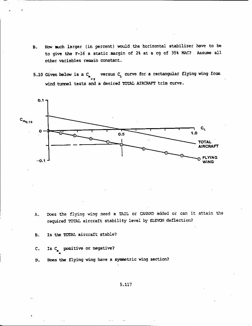
B. How mich larger (in percent) would the horizontal stabilizer have to be
to give the F-16 a static margin of 2% at a eg of 35% MAC? Assume all
other variables remain constant.
5.10 Given below is a C versus CT curve for a rectangular flying wing from
wind tunnel tests and a desired TOTAL AIRCRAFT trim curve.
0.1 -i
"»0.15
o-
-0.1 J
1 cL
TOTAL AIRCRAFT
FLYING WING
A. Does the flying wing need a TAIL or CANARD added or can it attain ths
required TOTAL aircraft stability level by ELEVON deflection?
B„ Is the TOTAL aircraft stable?
C. Is CB positive or negative? m
D. Does the flying wing have a symmetric wing section?
5.117

E. What is the flying wing's neutral point?
F. Is C positive or negative?
G. What is the static margin for this trim condition?
5.11 Given the flight test data shown below, show how to obtain the neutral
point(s). Label the two cg's tested as FWD and AFT.
5.
5.118

5.12 Given the curve shown below, show the effect of:
A. Shifting the eg FWD and retrimning to trim velocity.
B. Increasing C^ and retrimning to trim velocity.
C. Adding a downspring and retrimning to trim velocity.
D. Adding a bobweight and retrimning to trim velocity.
-Ve
5.13 Which changes in Problem 5.12 affect:
apparent stability actual stability
5.119

5.14 Read the question and answer true (T) or false (F).
T F if a body disturbed from equilibrium remains in the disturbed position it is statically unstable.
T F ~ Longitudinal static stability and "gust stability" are the same thing.
T F - Static longitudinal stability is a prerequisite for dynamic longitudinal stability.
T F Aircraft response in the X-Z plane (about the Y axis) usually cannot be considered as independent of the lateral directional motions.
T F Although C is a. direct indication of longitudinal static a
stability, C is relatively unimportant. > c L
T F At the USAF Test Pilot School elevator TEU and nose pitching up are positive in sign by convention. CAREFUL.
T F Tail efficiency factor and tail volume coefficient are not normally considered constant.
T F With the eg forward, an aircraft is more stable and maneuverable.
T F There are no well defined static stability criteria.
T F To call a canard surface a horizontal stabilizer is a misnomer.
T F The most stable wing contribution to stability results from a low wing forward of the eg.
T F With the eg aft, an aircraft is less maneuverable and more stable.
T F A thrust line below the eg is destabilizing for either a prop or turbojet.
T F The normal force contribution of either a prop or turbojet is destabilizing if the prop or inlet is aft of the aircraft eg.
T F A positive value of downwash derivatives causes a tail-to the-rear aircraft to be less stable if de/da is less than 1.0 than it would be if dc/do were equal to zero.
T F Verifying adequate stability and maneuverability at established eg limits is a legitimate flight test function.
T F An aircraft is balanced if it is forced to a negative value of Cm
for some useful positive value of CL. CG
5.120

T F An aircraft is considered stable if dCB /dCL is positive.
T F The slope of the C versus CT curve of an aircraft is a direct eg
measure of "gust stability."
T F Aircraft center of gravity position is only of secondary importance when discussing longitudinal static stability.
T F Due to the advance control system technology such as fly-by-wire, a basic knowledge of the requirements for natural aircraft stability is of little use to a sophisticated USAF test pilot.
T F Most contractors would encourage an answer of true (T), to the above question.
T F For an aircraft with a large vertical eg travel, the chordwise force contribution of the wing to stability probably cannot be neglected.
T F FWD and AFT eg limits are often determined from flight test.
T F A canard is a hoax. •
T F The value of stick-fixed static stability is equal to eg minus hn in percent MAC.
T F The stick-fixed static margin is stick-fixed stability with the sign reversed.
T F A slab tail (or stabilizer) is a more powerful longitudinal control than a two-piece elevator.
T F Elevator effectiveness and power are the same thing.
T F Elevator effectiveness is negative in sign , for a canard configuration.
T F Static margin is negative for a statically stable canard configuration.
T F Elevator power is positive in sign for either a tail-to-the-rear or a canard configuration.
T F Upwash causes a canard to be more destabilizing.
T F The main effect on longitudinal stability when accelerating to supersonic flight is caused by the shift in wing ac from 25% MAC to about 50% MAC.
T F The elevator of a reversible control system is normally statically balanced.
5.121

T F C is always negative and is known as the "restoring" moment 4
coefficient. T F (^ is always negative and is known as the "floating" moment
a
coefficient.
T F: With no pilot applied force a reversible elevator will "float" until hinge moments are zero.
T F A free elevator factor of one results in the stick-fixed and stick-free stability being the same.
T F Generally, freeing the elevator is destabilizing (tail-tc-the-rear).
T F Speed stability and stick force gradient about trim are the same.
T F Speed stability and apparent stability are the same.
T F Speed stability and stick-free stability are the same.
T F Dynamic control balancing is making C small or just slightly i
positive.
T F eg movement affects real and apparent stability (after retrimming).
T F Aerodynamic balancing affects real and apparent stability (after retrimming).
T Fr Downsprings and bobweights affect real and apparent stability (after retrimming).
T F In general, an aircraft becomes more stable supersonically which is characterized by an AFT shift in the neutral point.
T F Even though an aircraft is more stable supersonically (neutral point further AFT) it may have a speed instability.
T F The neutral point of the entire aircraft is analogous to the aerodynamic center of the wing by itself.
T F Aerodynamic balancing is "adjusting" or "tailoring" C^ and C^ .
T F Neutral point is a constant for a given configuration and is never a function of CL.
T F The eg location where dF /dV - 0 is the actual stick-free neutral point regardless of control system devices.
5.122

T F The effects of elevator weight on hinge moment coefficient are normally eliminated by static balance.
T F A positive 8# is a deflection causing a nose-up pitching moment.
T F A positive q is one defined as deflecting or trying to deflect the elevator in a negative direction.
T F C^ is normally negative (tail-to-the-rear) .'■ .
T F
T
T F
T F
T
(^ is always negative (tail-to-the-rear and canard) £
F C^ and Cjj are under control of the aircraft designer and can be a i t •
varied to "tailor" stick-free stability characteristics.
C^ and C^ are identical. a a
Cjj and (^ are not the same.
T F dFs/dV does not necessarily reflect actual stick-free stability characteristics.
F There are many ways to alter an aircraft's speed stability characteristics.
T F A bobweight can only be used to increase stick-force gradient.
T F CB cannot be determined from flight test.
5.123
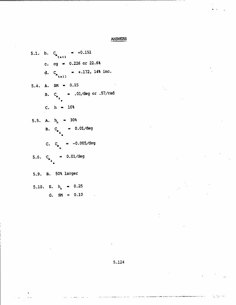
ANSWERS
5.1. b. C - +0.151 "t.ii
c. eg « 0.226 or 22.6%
d. C - +.172, 14% inc. tail
5.4. A. SM - 0.15
B. C - .01/deg or .57/rad
C. h - 10%
5.5. A. hn - 30%
B. C - 0.01/deg
C. C = -0.005/deg a
5.6. C - 0.01/deg
5.9. B. 50% larger
5.10. E. hn - 0.25
G. SM - 0.10
5.124
- /. »."
Bibliography
1. Perkins, C. D., and Hage, R. E., Airplane Performance Stability and Control, John Wiley & Sons, Inc., New York NY, 1949.
2. Phillips, W. H., Appreciation and Prediction of Flying Qualities, NACA Report 927, National Advisory Committee for Aeronautics, Washington DC,
1949.
3. Etkin, B., Dynamics of Atmospheric Flight, John Wiley & Sons, Inc., New York NY, 1972.
A. Kolk, W. R., Modern Flight Dynamics, Prentice-Hall, Inc., Englewood Cliffs NJ, 1961.
5. Perkins, CD., Editor, Flight Testing, Volume II, Stability and Control, North Atlantic Treaty Organization, Pergamon Press, New York NY, 1962.
6. Anon., Military Standard, Flying Qualities of Piloted Aircraft, MIL- STD-1797A, Department of Defense, Washington DC 20402, 30 Jan 90.
5.125