aircraft structural considerations j.b.rogers/structures j. byron rogers, p.e
Post on 22-Dec-2015
244 views
TRANSCRIPT
Aircraft Structural Aircraft Structural ConsiderationsConsiderations
J.B.Rogers/Structures
J. Byron Rogers, P.E.J. Byron Rogers, P.E.

Structural Considerations
• The structure will not fail!
- Not statically under any static design ultimate load case
• Ultimate Load is typically 1.5 * Limit Load
• Covers part tolerances, statistical allowables, load exceedance
- Not after repeated loads within the lifetime of the vehicle
• The structure will not deflect such that something does not work anymore!
- Doors will open when they are supposed to
- Nothing will yield
- Control surfaces will move through expected range
- No unexpected shock waves will form
• Structure will meet specified durability/ damage tolerance/ fail safety requirements.
- No failures with specified damage within allowed inspection intervals
In Simple Terms
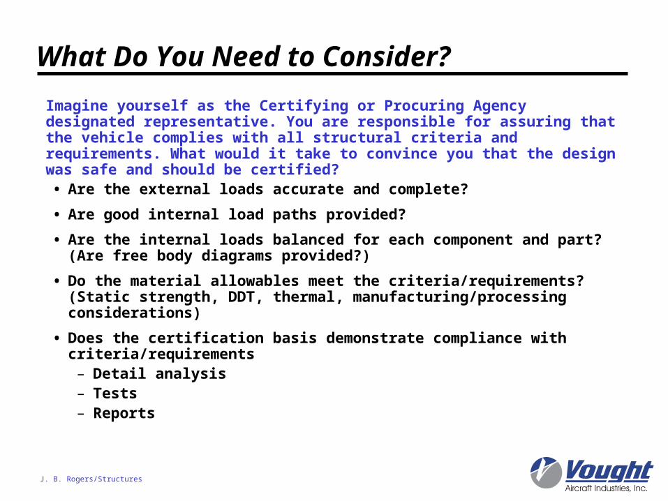
What Do You Need to Consider?
• Are the external loads accurate and complete?
• Are good internal load paths provided?
• Are the internal loads balanced for each component and part? (Are free body diagrams provided?)
• Do the material allowables meet the criteria/requirements? (Static strength, DDT, thermal, manufacturing/processing considerations)
• Does the certification basis demonstrate compliance with criteria/requirements– Detail analysis– Tests– Reports
J. B. Rogers/Structures
Imagine yourself as the Certifying or Procuring Agency designated representative. You are responsible for assuring that the vehicle complies with all structural criteria and requirements. What would it take to convince you that the design was safe and should be certified?
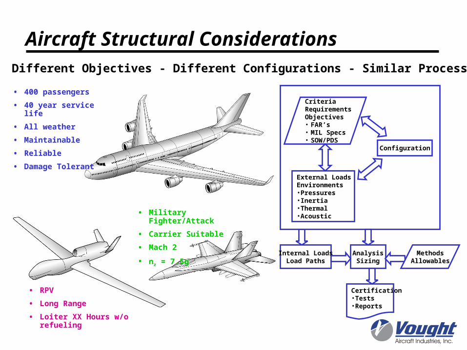
• 400 passengers
• 40 year service life
• All weather
• Maintainable
• Reliable
• Damage Tolerant
• RPV
• Long Range
• Loiter XX Hours w/o refueling
Different Objectives - Different Configurations - Similar Process
Aircraft Structural Considerations
• Military Fighter/Attack
• Carrier Suitable
• Mach 2
• nz = 7.5g Internal LoadsLoad Paths
AnalysisSizing
CriteriaRequirementsObjectives• FAR’s• MIL Specs• SOW/PDS
Configuration
External LoadsEnvironments•Pressures•Inertia•Thermal•Acoustic
MethodsAllowables
Certification•Tests•Reports
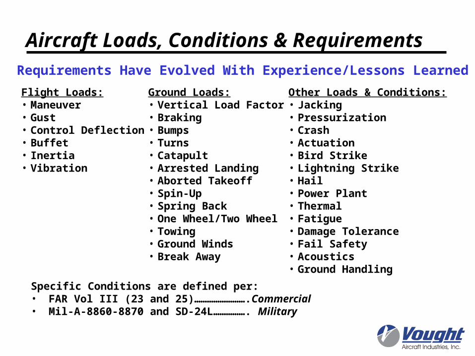
Aircraft Loads, Conditions & Requirements
Flight Loads:• Maneuver• Gust• Control Deflection• Buffet• Inertia• Vibration
Ground Loads:• Vertical Load Factor• Braking• Bumps• Turns• Catapult• Arrested Landing• Aborted Takeoff• Spin-Up• Spring Back• One Wheel/Two Wheel• Towing• Ground Winds• Break Away
Other Loads & Conditions:• Jacking• Pressurization• Crash• Actuation• Bird Strike• Lightning Strike• Hail• Power Plant• Thermal• Fatigue• Damage Tolerance• Fail Safety• Acoustics• Ground Handling
Specific Conditions are defined per:• FAR Vol III (23 and 25)…………………….Commercial• Mil-A-8860-8870 and SD-24L……………. Military
Requirements Have Evolved With Experience/Lessons Learned
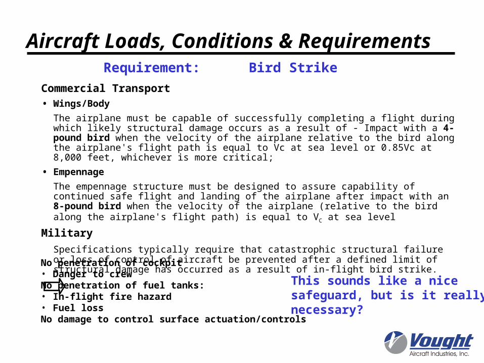
Commercial Transport
• Wings/Body
The airplane must be capable of successfully completing a flight during which likely structural damage occurs as a result of - Impact with a 4-pound bird when the velocity of the airplane relative to the bird along the airplane's flight path is equal to Vc at sea level or 0.85Vc at 8,000 feet, whichever is more critical;
• Empennage
The empennage structure must be designed to assure capability of continued safe flight and landing of the airplane after impact with an 8-pound bird when the velocity of the airplane (relative to the bird along the airplane's flight path) is equal to VC at sea level
Military
Specifications typically require that catastrophic structural failure or loss of control of aircraft be prevented after a defined limit of structural damage has occurred as a result of in-flight bird strike.
Requirement: Bird Strike
No penetration of cockpit• Danger to crewNo penetration of fuel tanks:• In-flight fire hazard• Fuel lossNo damage to control surface actuation/controls
This sounds like a nicesafeguard, but is it really necessary?
Aircraft Loads, Conditions & Requirements
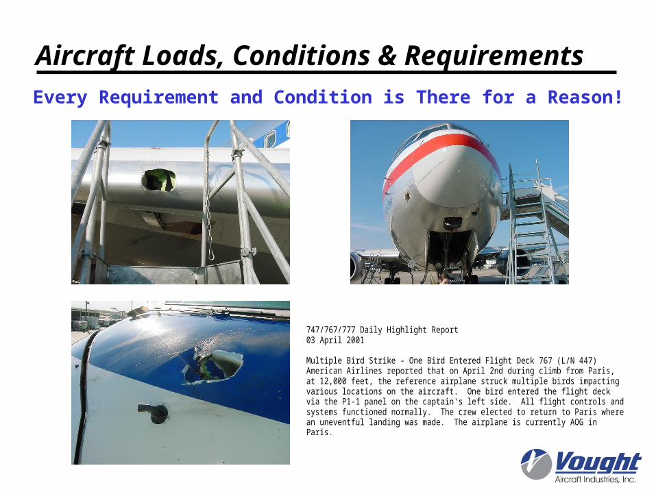
Every Requirement and Condition is There for a Reason!
747/767/777 Daily Highlight Report03 April 2001
Multiple Bird Strike - One Bird Entered Flight Deck 767 (L/N 447)American Airlines reported that on April 2nd during climb from Paris,at 12,000 feet, the reference airplane struck multiple birds impactingvarious locations on the aircraft. One bird entered the flight deckvia the P1-1 panel on the captain's left side. All flight controls andsystems functioned normally. The crew elected to return to Paris wherean uneventful landing was made. The airplane is currently AOG inParis.
Aircraft Loads, Conditions & Requirements
• USAF - 34,856 bird strikes reported between Jan 1985 and Feb 1998– 33,262 non-damaging (less than $10,000)– 7,358 struck wings– 764 were Horned Larks– 348 were Turkey Vultures (+98 Black Vultures)
• Over 25,000 reported strikes to Civil aircraft between 1988 and 1992
• CAA estimates that UK registered A/C of over 12,000 lbs strike a bird about once every 1,000 flights
Aircraft Loads, Conditions & RequirementsRequirement: Bird Strike
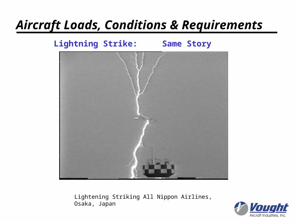
Lightening Striking All Nippon Airlines, Osaka, Japan
Lightning Strike: Same Story
Aircraft Loads, Conditions & Requirements
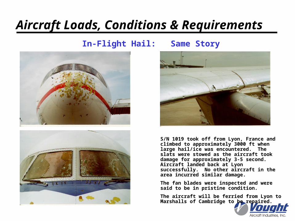
In-Flight Hail: Same Story
S/N 1019 took off from Lyon, France and climbed to approximately 3000 ft when large hail/ice was encountered. The slats were stowed as the aircraft took damage for approximately 3-5 second. Aircraft landed back at Lyon successfully. No other aircraft in the area incurred similar damage.
The fan blades were inspected and were said to be in pristine condition.
The aircraft will be ferried from Lyon to Marshalls of Cambridge to be repaired.
Aircraft Loads, Conditions & Requirements

Yaw Maneuver andLateral Gust
Buffet
Positive CheckedManeuver
Negative CheckedManeuver
Negative Maneuver
Lateral Maneuver
Negative Gust
Engine Blade Out
Taxi
Negative Maneuverand Braking
Gust
Cabin Pressure
Aileron Roll
Positive DynamicGust
Positive Maneuverand Static Gust
Aircraft Loads, Conditions & Requirements
Different Load Conditionsare Critical for Different Areas
Typical Commercial Transport Critical Static Load Conditions
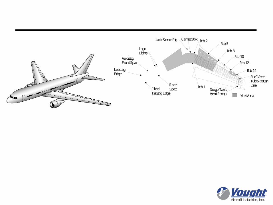
Auxiliary Front Spar
LeadingEdge
RearSpar
LogoLights
FixedTrailing Edge
Surge TankVent Scoop
Rib 5
Rib 8
Rib 10
Rib 12
Rib 14
Wet Area
Jack Screw Ftg Rib 2
Rib 1
Center Box
Fuel VentTube/ReturnLine
Surge Tank
• External loads (pressures/inertia)• Durability/Damage Tolerance• Crash• Failed Refueling Valve• Hail and bird strike• Lightning strike• Material utilization
Structural ConsiderationsBird Strike
Stall Buffet Failed RefuelValve
Abrupt Up Elevator
Lightning Strikeminimum skin thickness
Upper Surface Skin/StringersDurability/Damage TolerancePositive Maneuver
Lower Surface Skin/StringersNegative Maneuver
Abrupt Elevator
Negative Maneuver
Balanced Maneuver
Negative Gust
Stall Buffet9G Crash
3G Side LoadCrash
Typical Commercial Transport Critical Load Conditions
Aircraft Loads, Conditions & Requirements
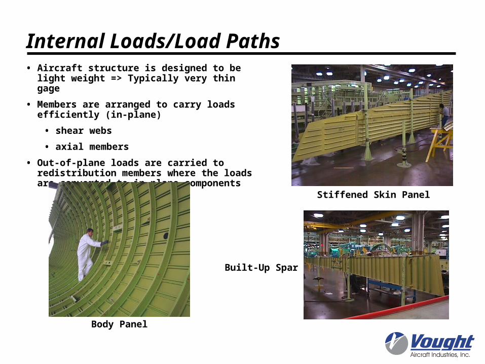
Internal Loads/Load Paths• Aircraft structure is designed to be light weight
=> Typically very thin gage
• Members are arranged to carry loads efficiently (in-plane)
• shear webs
• axial members
• Out-of-plane loads are carried to redistribution members where the loads are converted to in-plane components
Stiffened Skin Panel
Built-Up Spar
Body Panel
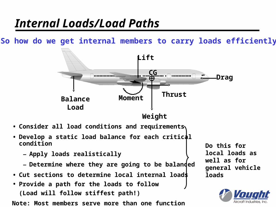
• Consider all load conditions and requirements
• Develop a static load balance for each critical condition
– Apply loads realistically
– Determine where they are going to be balanced
• Cut sections to determine local internal loads
• Provide a path for the loads to follow
(Load will follow stiffest path!)
Note: Most members serve more than one function
So how do we get internal members to carry loads efficiently?
Do this for local loads as well as for general vehicle loads
Internal Loads/Load Paths
Lift
ThrustBalance
LoadMoment
Weight
CGDrag
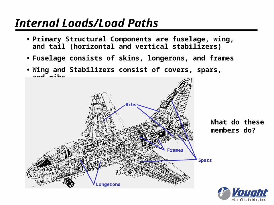
• Primary Structural Components are fuselage, wing, and tail (horizontal and vertical stabilizers)
• Fuselage consists of skins, longerons, and frames
• Wing and Stabilizers consist of covers, spars, and ribs
Spars
Ribs
Frames
Longerons
What do these members do?
Internal Loads/Load Paths

For a downward tail load, body will carry a shear and a bending moment
Skins carry shear load in-plane with VQ/I distribution
Lower longerons (with effective skin)carry compression axial loads due tobending moment
Crown longerons and skin carry tension loads due to bending moment
Bending moment is carried based on Mc/I distribution
Consider fuselage to act as a beam
Keel Beam added to restore load path on lower surface (wing carry through and wheel well areas)
z
y
0.31.82
16.57
71.32
66.62
57.22
-31.82-16.57
-57.22
-66.62
-71.32
-66.62
-57.22-31.82
-16.57 0. 16.5731.82
57.22
66.62
Bruhn Figure A21.62
12
3
4
5
6
7
8
9
1011 11'
10'
9'
8'
7'
6'
5'
4'
3'
2'1'
zy
2000 200011.5" 11.5"
Bruhn Section 21.12 (Fig A21.62)
Internal Loads/Load Paths - Fuselage
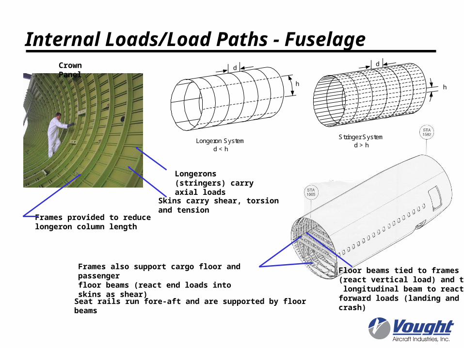
Longerons (stringers) carry axial loads
Frames provided to reducelongeron column length
Skins carry shear, torsionand tension
Frames also support cargo floor and passenger floor beams (react end loads into skins as shear)
Seat rails run fore-aft and are supported by floor beams
Floor beams tied to frames (react vertical load) and to a longitudinal beam to react forward loads (landing and crash)
d
h
Stringer Systemd > h
d
h
Longeron Systemd < h
Internal Loads/Load Paths - FuselageCrown Panel

Body skins also carry external and compartmentpressures as a membrane.
For duel-lobe configurations, longitudinal beam(crease beam) and floor beams react out-of-planeload component at lobe intersection
Internal Loads/Load Paths - Fuselage

Internal Loads/Load Paths - Wing/Stabilizer
Internal structure consists primarily of Covers, Spars, and Ribs

Elastic Axis
Wing acts like cantilevered beamunder distributed pressure loading.Shear, Moment, and Torsion (about elastic axis) are beamed to fuselage and balance tail load, inertia, and other side wing load.
Typical VMT for Horizontal Stabilizer
-50
0
50
100
150
200
250
0 0.2 0.4 0.6 0.8 1 1.2
Percent Semispan
Sh
ea
r (1
0^
3 lb
s),
Mo
me
nt
(10
^5
in-
lbs
), T
ors
ion
(1
0^
5 in
-lb
s)
Shear (V)
Moment (M)
Torsion (T)
Internal Loads/Load Paths - Wing/Stabilizer
VT
M
VT

Transports & Bombers• Deep Sections• Skin Supported by
Stringers Carries Bending Moments
Fighters• Thin Sections• Unstiffened Skins• Skin and Spar
Chords Carry Bending Moment
Section Bending Moments
Main Types of Wing Primary Structure
Thin Skin ( many stringers and ribs) Thick Skin ( many spars, few ribs)
Stringers would not be efficient
Section Shear Flow
Vz = 1000 lbs
23.3
17.410.07.728.3
51.9
28.3 7.7 10.0 17.4
Vz = 1000 lbs
7.74
1.845.534.716.44
18.5118.8111.23 18.92
6.44 4.71 5.53 1.84
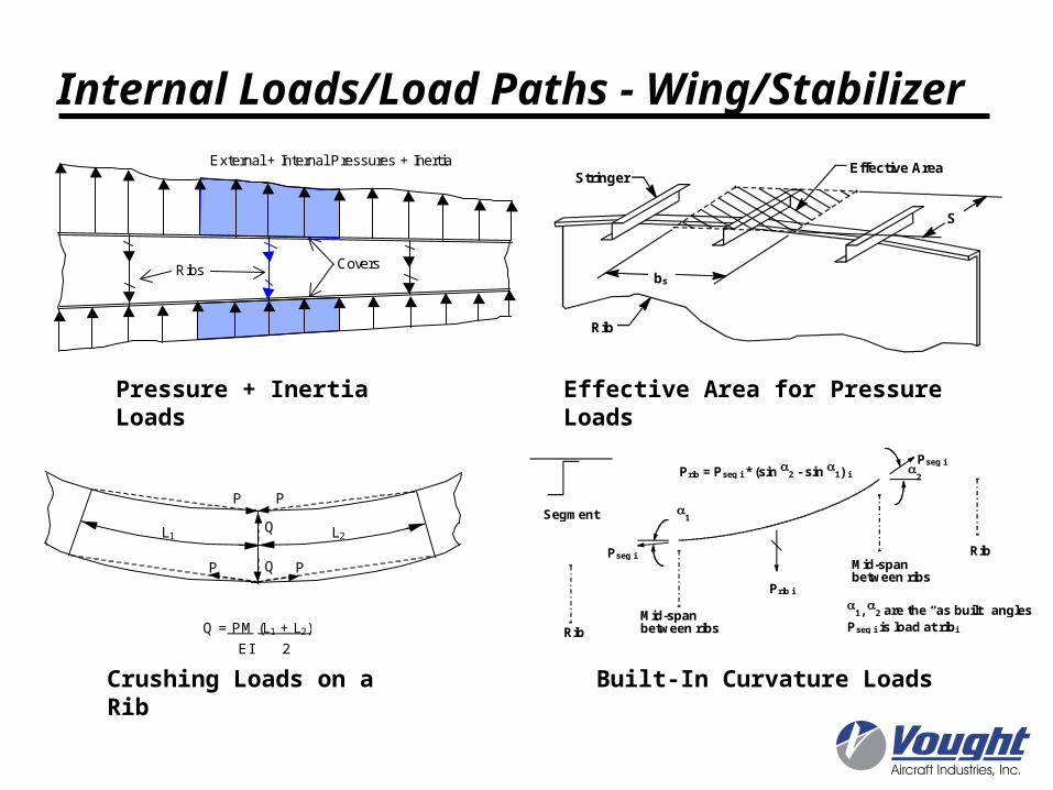
Internal Loads/Load Paths - Wing/Stabilizer
Spar Webs Carry Shear (V)Shell Carries Torque (T)
2
1
Pseg i
Pseg i
Prib i
Prib = Pseg i * (sin 2 - sin 1) i
Mid-spanbetween ribs
Mid-spanbetween ribs
Rib
Rib
1, 2 are the “as built” angles
Pseg i is load at ribi
Segment
Built-In Curvature Loads
bs
S
StringerEffective Area
Rib
Effective Area for Pressure Loads
PP
P P
L1 L2Q
Q
Q = PM (L1 + L2)
EI 2
Crushing Loads on a Rib
Pressure + Inertia Loads
Ribs Covers
External + Internal Pressures + Inertia
Internal Loads/Load Paths - Wing/Stabilizer
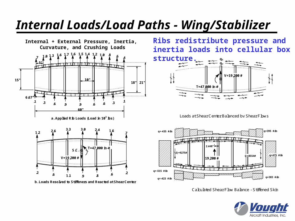
.1 .3 .6 .9 .9 .6 .6 .3 .1
.7 1.0 1.3 1.6 1.7 1.6 1.2 1.0 .8 .6 .41.41.5
10"15"
5"
6.67"
21"18"
60"
.2 .6 1.1 .9 .8 .6 .2
1.2 2.6 3.3 2.4 1.6.7
3.0
S.C.
V=19,200 #
a. Applied Rib Loads (Load in 103 lbs)
b. Loads Resolved to Stiffeners and Reacted at Shear Center
T=47,000 in-#
qt
qv
V=19,200 #
T=47,000 in-#
Loads at Shear Center Balanced by Shear Flows
2.448"
19,200 #
q=-515 #/in
q=-435 #/in
q=-423 #/in
q=395 #/in
q=383 #/in
q=475 #/inQ=9275#
Q=8554#
Calculated Shear Flow Balance - Stiffened Skin
Internal + External Pressure, Inertia, Curvature, and Crushing Loads
Internal Loads/Load Paths - Wing/StabilizerRibs redistribute pressure and inertia loads into cellular box structure.
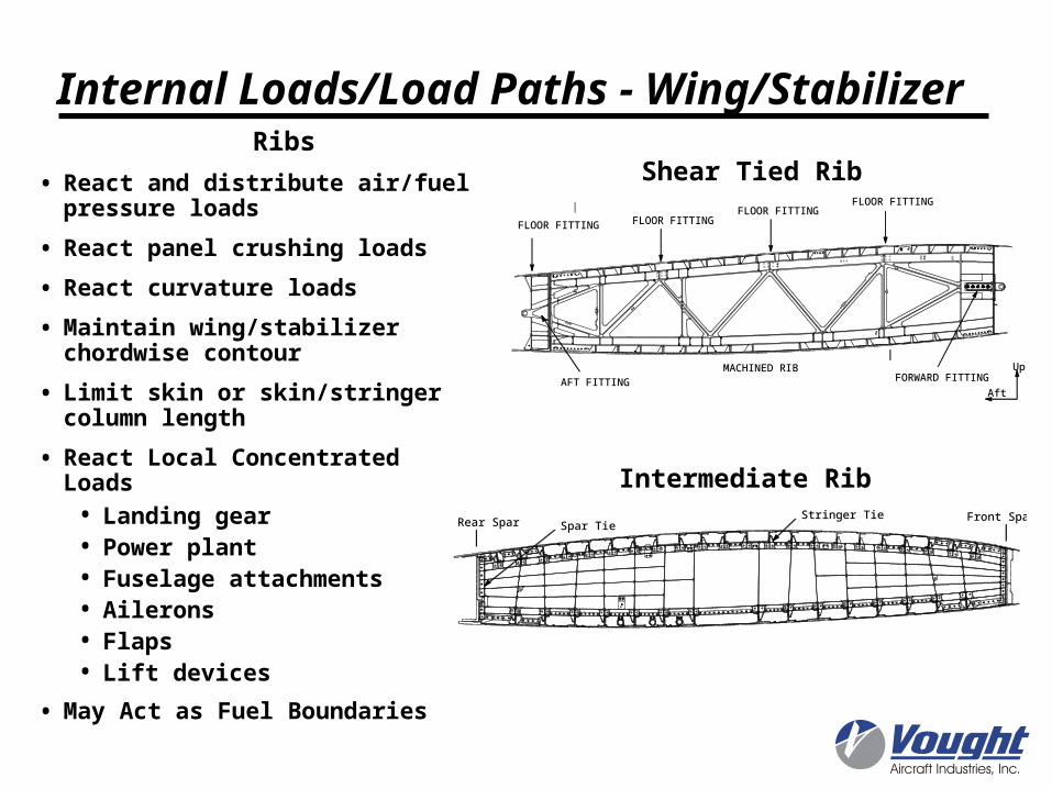
Ribs
• React and distribute air/fuel pressure loads
• React panel crushing loads
• React curvature loads
• Maintain wing/stabilizer chordwise contour
• Limit skin or skin/stringer column length
• React Local Concentrated Loads• Landing gear• Power plant• Fuselage attachments• Ailerons• Flaps• Lift devices
• May Act as Fuel Boundaries
Rear Spar Front SparStringer TieSpar Tie
AFT FITTING FORWARD FITTING MACHINED RIB
FLOOR FITTINGFLOOR FITTING
FLOOR FITTING FLOOR FITTING
Up
Aft
Shear Tied Rib
Intermediate Rib
Internal Loads/Load Paths - Wing/Stabilizer

Rib 2
Rib 8
136.3" 83.0"
219.3"
If the time ‘T’ for fuel to flow from the upstream side of the barrier to fill a volume of air defined in the 1g flight condition is greater that 0.5 second, the internal baffle can be considered to be a solid pressure barrier.
Conversely, an internal baffle may not be considered as a pressure boundary if the volume of air in the fuel cell downstream of the barrier is not adequate to meet the above criteria. In such cases, the pressures due to the hydrostatic fuel head must be calculated without consideration of this internal baffle.
P = 0.34 * K * L (6.5 pound/gallon fuel density)
Where: P = design pressure at location ‘a’; L = reference distance, feet, between the point of pressure and the farthest tank boundary in the direction of loading; K is defined in the table.
Emergency Landing (Crashworthy) Fuel Loads
Fuel Loading - Roll Rate Loading Condition KForward 9
Aft 1.5Inboard 1.5
Outboard 1.5Downward 6
Upward 3
Internal Loads/Load Paths - Wing/Stabilizer
F = Mr2
F = Mr
= angular acceleration = angular velocity
r

Concentrated Loads
• Landing Gear
• Power Plant
• Fuselage Attachments
• Ailerons
• Flaps
• Lift devices
Engine Pylon
Wing Elastic Axis
PP C.G.
Front Spar
Ribs redistribute concentrated loads into cellular box structure.
Internal Loads/Load Paths - Wing/Stabilizer
Chord
Upright or Rib Post
Web
ChordStrut
Rib Post
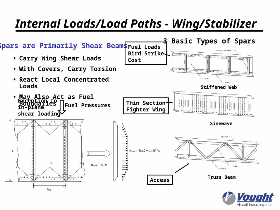
• Carry Wing Shear Loads
• With Covers, Carry Torsion
• React Local Concentrated Loads
• May Also Act as Fuel Boundaries
Spars are Primarily Shear Beams3 Basic Types of Spars
Stiffened Web
Sinewave
Truss Beam
Exception toin-plane shear loading
Fuel Pressures
Fuel LoadsBird StrikeCost
Access
Thin SectionFighter Wing
bs1
L wmax = (bs1/2 + bs2/2) * p
bs1/2 + bs2/2
Internal Loads/Load Paths - Wing/Stabilizer
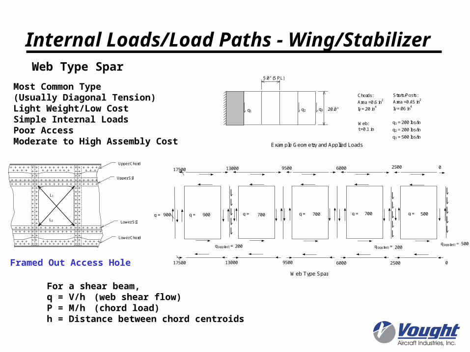
5.0" (5 PL)
20.0"
Chords:
Area =0.6 in2
Iy =.20 in4
Struts/Posts:
Area =0.45 in2
Iy =.06 in4
Web:t =0.1 in
q1 q2 q3
q1 = 200 lbs/in
q2 = 200 lbs/in
q3 = 500 lbs/in
0
500
500700700700900
0
200200
9500 6000 250017500 13000
900 q = q =q =q =q = q =
25009500 60001300017500
q(applied) =q(applied) =q(applied) =
Web Type Spar
Example Geometry and Applied Loads
Most Common Type(Usually Diagonal Tension)Light Weight/Low CostSimple Internal LoadsPoor AccessModerate to High Assembly Cost
For a shear beam, q = V/h (web shear flow)P = M/h (chord load)h = Distance between chord centroids
Upper Chord
Lower Chord
Upper Sill
Lower Sill
L1
L2
Framed Out Access Hole
Web Type Spar
Internal Loads/Load Paths - Wing/Stabilizer
q =900 lbs/in q =900 lbs/in
q(applied) =500 lbs/in
9500 2,5002,500 2,50017,500 9500
10,00010,307
6,000
10,307
6,000
14,431
4,000
14,431
06,000
14,431
9500
14,43114,431
13,000
0
13,000
0
14,00014,431
13,000
17,500
q(applied) =200 lbs/in
q(applied) = 200 lbs/in
0
q =900 lbs/in q =900 lbs/in q(applied) =500 lbs/in
9514 2,4202,676 2,48917,500 9,514
8,936
9,151
5,996
12,974
5,996
13,657
9514
13,657
11,014
12,336
1,207
12,336
0
14,000
11,014
14,970
17,500
q(applied) =200 lbs/in
q(applied) = 200 lbs/in
2,6769514
5,99613,000
87
119
5,996
12,9742,793
155
1064
3558
1763 155
1064
1064155
1551339
1763
248987
1,985
1,294
3,871
119
1,081
9,151
1,361
187
1,844
1871,827
163
1,422
1791,775
163 609
179 1,908
1,294
2,600
640
1,727 640
1,473
212
2,210
212
2165
155
155
2,210
1872
163
205
163
6092,712
9,685
2,712
3,877
640
4,926640
1,727
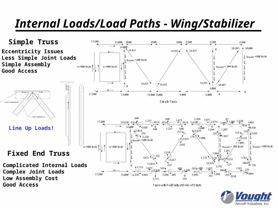
Truss with Full Fixity at Ends of Struts
Simple Truss
Complicated Internal LoadsComplex Joint LoadsLow Assembly CostGood Access
Eccentricity IssuesLess Simple Joint LoadsSimple AssemblyGood Access
Chord Centroidal Axis
Strut Centroidal Axis
Line Up Loads!
Simple Truss
Fixed End Truss
Internal Loads/Load Paths - Wing/Stabilizer
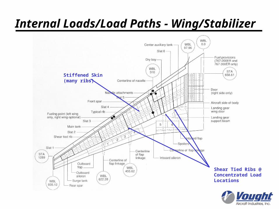
Stiffened Skin(many ribs)
Shear Tied Ribs @ Concentrated Load Locations
Internal Loads/Load Paths - Wing/Stabilizer
Internal Loads/Load Paths - Arrangement
This Slide Intentionally Left BlankSee Class Handout

Longeron System(d < h)
Multi-Spar(unstiffenedskins, few ribs)
Frames @ Concentrated Load Points
Frames @ Direction Changes in Load Carrying Members
Wing Fold
Internal Loads/Load Paths - Arrangement

Multi-Spar(unstiffenedskins, few ribs)
Longeron System(d < h)
Dielectric material
Stub Ribs
Frames @ Concentrated Load Points
Wing Fold
Internal Loads/Load Paths - Arrangement

Deep SectionStiffened Skins(many ribs)
No Fuselage, No Vertical Stabilizer
Ribs @ Concentrated Load Points
Internal Loads/Load Paths - Arrangement
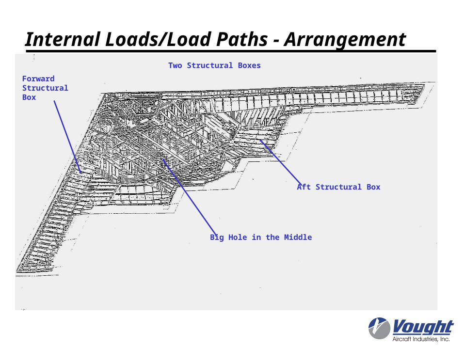
Two Structural Boxes
ForwardStructuralBox
Aft Structural Box
Big Hole in the Middle
Internal Loads/Load Paths - Arrangement
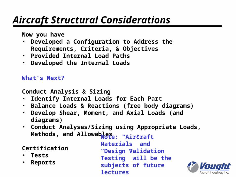
Aircraft Structural ConsiderationsNow you have • Developed a Configuration to Address the Requirements,
Criteria, & Objectives• Provided Internal Load Paths• Developed the Internal Loads
What’s Next?
Conduct Analysis & Sizing• Identify Internal Loads for Each Part• Balance Loads & Reactions (free body diagrams)• Develop Shear, Moment, and Axial Loads (and diagrams)• Conduct Analyses/Sizing using Appropriate Loads, Methods, and
Allowables
Certification• Tests• Reports
Note: “Aircraft Materials” and “Design Validation Testing” will be the subjects of future lectures

Web shear flows and stiffener loads were developed for each load condition
676
79 18 18 86
689
7.45" 60 41
439 440
48
451 452
-11
675 19421875
156 165
2482 582 583 893 895 909 596 597 2566
67
18 13860 41 48-11 67134
54 107115 38 3665 11591
372 22 832294 216 143 22397 302759
18 5460 41 48-11 6747 5447
-1031890 367 -861 -1767 -2085 -955 -245 760 2279
103
-420-259 -451 -441 -597 432 389 557
420
Internal Load Balance
In-Plane Load Balance
Shear flow (lbs/in)
Lateral stiffener loads (lbs)
Fore-aft stiffener loads (lbs)

88.4p lbs
Internal Load Balance
wmax = 7.475p lbs/in
88.4p lbs104.9p lbs
58.61 in
23.1p lbs23.1p lbs
V
M
M = 1665p in- lbs
104.9p lbs
p = Pressure (psi)
Load Balance:• Normal Pressures• In-Plane Components
Develop shear, moment, axial, and torsion diagrams

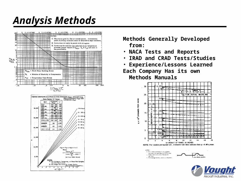
Analysis MethodsMost Methods are Unique to Aerospace Industry and are Semi-empirical
• Diagonal Tension– Forced Crippling– Permanent Buckling– Gross Allowable Web Stress (Shear Rupture)– Secondary Bending Moments
• Lightening Holes/Flanged Holes• Beaded Shear Panels• Local Buckling• Crippling• Effective Width of Buckled Sheet• Sheet Wrinkling• Buckling in Bending
– Formed members with or w/o attached skin– Extruded members with or w/o attached skin
• Tension Fittings/Clips• Lugs• Joggles• Bearing/Bypass Interaction @ Fastened Joints• Effects of Defects
Most Static Load Critical Structure is Stability Driven
Analysis Methods
Methods Generally Developed from:• NACA Tests and Reports• IRAD and CRAD Tests/Studies• Experience/Lessons LearnedEach Company Has its own Methods
Manuals

CONSTRAINTS
• C/S Depth
• Skin min gage (.08”fuel areas or .05” other)
• Stringer attach flange width (e/d & clearance)
• Minimum stringer machining gage (.05”)
• Producibility
STATIC CHECKS ( Each Stringer; Each Rib Bay)
• Crippling
• Johnson-Euler Column (Axial Compression) Fixity Coefficient C = 1
• Johnson-Euler Column (Axial Compression) + Shear C = 1
• Flexure (pressure acting singularly, C = 4)
• Beam Column (C = 4)
• Skin Stability between stringers (compression + shear) @ Cruise
• Preliminary D/DT Cutoff
• Flexure-Torsion Mode Stability
• Pure Torsion Mode Stability
bF
bA
tF
tO tAH
bS
tF
tOpad
Preliminary Sizing - CT Horizontal Stabilizer Main Box Cover Panel
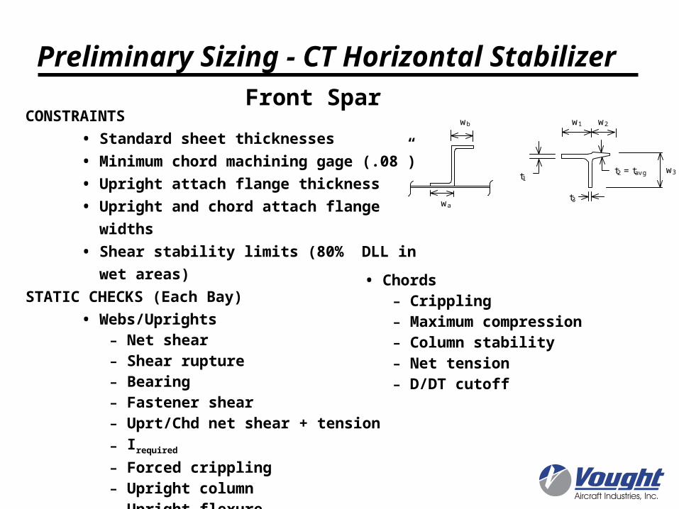
CONSTRAINTS
• Standard sheet thicknesses
• Minimum chord machining gage (.08”)
• Upright attach flange thickness
• Upright and chord attach flange widths
• Shear stability limits (80% DLL in wet areas)
STATIC CHECKS (Each Bay)
• Webs/Uprights
- Net shear
- Shear rupture
- Bearing
- Fastener shear
- Uprt/Chd net shear + tension
- Irequired
- Forced crippling
- Upright column
- Upright flexure
• Chords
- Crippling
- Maximum compression
- Column stability
- Net tension
- D/DT cutoff
t1
t3
t2 = tav g w3
w1 w2wb
wa
Preliminary Sizing - CT Horizontal StabilizerFront Spar
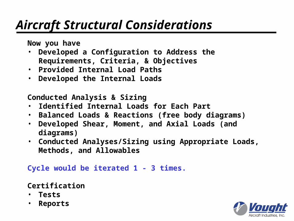
Aircraft Structural ConsiderationsNow you have • Developed a Configuration to Address the Requirements,
Criteria, & Objectives• Provided Internal Load Paths• Developed the Internal Loads
Conducted Analysis & Sizing• Identified Internal Loads for Each Part• Balanced Loads & Reactions (free body diagrams)• Developed Shear, Moment, and Axial Loads (and diagrams)• Conducted Analyses/Sizing using Appropriate Loads, Methods,
and Allowables
Cycle would be iterated 1 - 3 times.
Certification• Tests• Reports
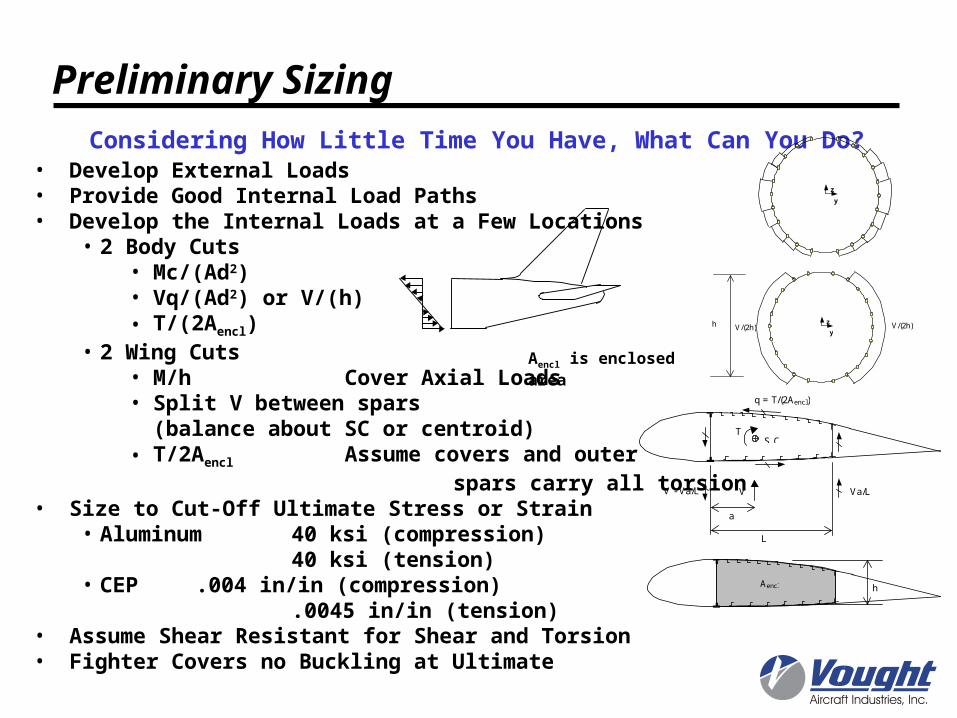
Preliminary SizingConsidering How Little Time You Have, What Can You Do?
• Develop External Loads• Provide Good Internal Load Paths• Develop the Internal Loads at a Few Locations
• 2 Body Cuts• Mc/(Ad2)• Vq/(Ad2) or V/(h)• T/(2Aencl)
• 2 Wing Cuts• M/h Cover Axial Loads• Split V between spars
(balance about SC or centroid)• T/2Aencl Assume covers and outer
spars carry all torsion• Size to Cut-Off Ultimate Stress or Strain
• Aluminum 40 ksi (compression)40 ksi (tension)
• CEP .004 in/in (compression).0045 in/in (tension)
• Assume Shear Resistant for Shear and Torsion• Fighter Covers no Buckling at Ultimate
Aencl is enclosed area
Aencl h
S.C.T
V
a
L
Va/LV - Va/L
q = T/(2Aencl)
z
yh V/(2h)V/(2h)
z
y