aircraft structures structural & loading discontinuities · 2019-03-06 · • shearing of...
TRANSCRIPT

University of Liège
Aerospace & Mechanical Engineering
Aircraft Structures
Structural & Loading Discontinuities
Aircraft Structures - Structural & Loading Discontinuities
Ludovic Noels
Computational & Multiscale Mechanics of Materials – CM3
http://www.ltas-cm3.ulg.ac.be/
Chemin des Chevreuils 1, B4000 Liège

Elasticity
• Balance of body B– Momenta balance
• Linear
• Angular
– Boundary conditions• Neumann
• Dirichlet
• Small deformations with linear elastic, homogeneous & isotropic material
– (Small) Strain tensor , or
– Hooke’s law , or
with
– Inverse law
with
b
T
n
2ml = K - 2m/3
2013-2014 Aircraft Structures - Structural & Loading Discontinuities 2

• General expression for unsymmetrical beams
– Stress
With
– Curvature
– In the principal axes Iyz = 0
• Euler-Bernoulli equation in the principal axis
– for x in [0 L]
– BCs
– Similar equations for uy
Pure bending: linear elasticity summary
x
z f(x) TzMxx
uz =0
duz /dx =0 M>0
L
y
zq
Mxx
a
2013-2014 Aircraft Structures - Structural & Loading Discontinuities 3
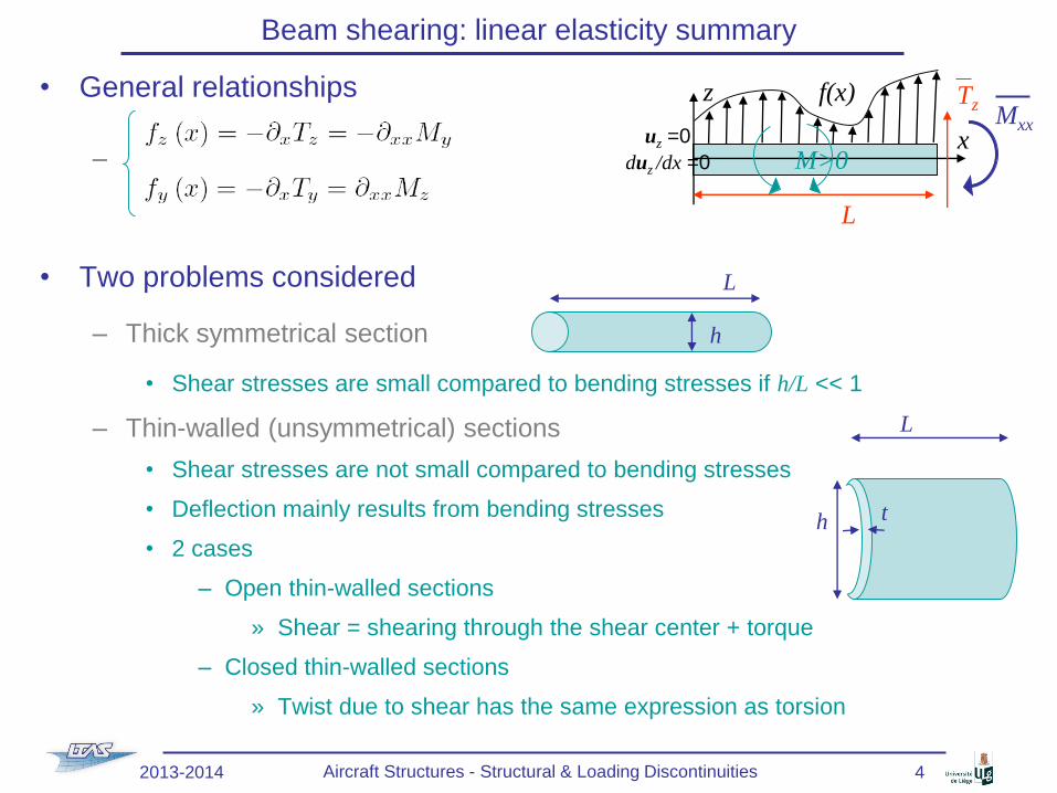
• General relationships
–
• Two problems considered
– Thick symmetrical section
• Shear stresses are small compared to bending stresses if h/L << 1
– Thin-walled (unsymmetrical) sections
• Shear stresses are not small compared to bending stresses
• Deflection mainly results from bending stresses
• 2 cases
– Open thin-walled sections
» Shear = shearing through the shear center + torque
– Closed thin-walled sections
» Twist due to shear has the same expression as torsion
Beam shearing: linear elasticity summary
x
z f(x) TzMxx
uz =0
duz /dx =0 M>0
L
h
L
L
h t
2013-2014 Aircraft Structures - Structural & Loading Discontinuities 4

• Shearing of symmetrical thick-section beams
– Stress
• With
• Accurate only if h > b
– Energetically consistent averaged shear strain
• with
• Shear center on symmetry axes
– Timoshenko equations
• &
• On [0 L]:
Beam shearing: linear elasticity summary
ht
z
y
z
t
b(z)
A*
t
h
x
z
Tz
dx
Tz+ ∂xTz dx
gmax
gg dx
z
x
g
qy
qy
2013-2014 Aircraft Structures - Structural & Loading Discontinuities 5

• Shearing of open thin-walled section beams
– Shear flow
•
• In the principal axes
– Shear center S
• On symmetry axes
• At walls intersection
• Determined by momentum balance
– Shear loads correspond to
• Shear loads passing through the shear center &
• Torque
Beam shearing: linear elasticity summary
x
z
y
Tz
Tz
Ty
Ty
y
z
S
Tz
TyC
q
s
y
t
t
h
b
z
C
t
S
2013-2014 Aircraft Structures - Structural & Loading Discontinuities 6

• Shearing of closed thin-walled section beams
– Shear flow
•
• Open part (for anticlockwise of q, s)
• Constant twist part
• The q(0) is related to the closed part of the section,
but there is a qo(s) in the open part which should be
considered for the shear torque
Beam shearing: linear elasticity summary
y
z
T
Tz
Ty
C
q s
pds
dAh
y
z
T
Tz
Ty
C
q s
p
2013-2104 Aircraft Structures - Structural & Loading Discontinuities 7

• Shearing of closed thin-walled section beams
– Warping around twist center R
•
• With
– ux(0)=0 for symmetrical section if origin on
the symmetry axis
– Shear center S
• Compute q for shear passing thought S
• Use
With point S=T
Beam shearing: linear elasticity summary
y
z
T
Tz
Ty
C
q s
pds
dAh
y
z
S
Tz
C
q s
p ds
2013-2014 Aircraft Structures - Structural & Loading Discontinuities 8

• Torsion of symmetrical thick-section beams
– Circular section
•
•
– Rectangular section
•
•
• If h >> b
– &
–
–
Beam torsion: linear elasticity summary
t
z
y
C
Mx
r
h/b 1 1.5 2 4 ∞
a 0.208 0.231 0.246 0.282 1/3
b 0.141 0.196 0.229 0.281 1/3
z
y
C
tmaxMx
b
h
2013-2014 Aircraft Structures - Structural & Loading Discontinuities 9

• Torsion of open thin-walled section beams
– Approximated solution for twist rate
• Thin curved section
–
–
• Rectangles
–
–
– Warping of s-axis
•
Beam torsion: linear elasticity summary
y
z
l2
t2
l1
t1
l3
t3
t
t
z
y
C
Mx
t
ns
t
R
pR
us
q
2013-2014 Aircraft Structures - Structural & Loading Discontinuities 10

• Torsion of closed thin-walled section beams
– Shear flow due to torsion
– Rate of twist
•
• Torsion rigidity for constant m
– Warping due to torsion
•
• ARp from twist center
Beam torsion: linear elasticity summary
y
z
C
q s
pds
dAh
Mx
y
z
R
C p
pRY
us
q
2013-2014 Aircraft Structures - Structural & Loading Discontinuities 11

• Panel idealization
– Booms’ area depending on loading
• For linear direct stress distribution
Structure idealization summary
b
sxx1
sxx2
A1 A2
y
z
x
tD
b
y
z
xsxx
1sxx
2
2013-2014 Aircraft Structures - Structural & Loading Discontinuities 12

• Consequence on bending
– If Direct stress due to bending is carried by booms only
• The position of the neutral axis, and thus the second moments of area
– Refer to the direct stress carrying area only
– Depend on the loading case only
• Consequence on shearing
– Open part of the shear flux
• Shear flux for open sections
• Consequence on torsion
– If no axial constraint
• Torsion analysis does not involve axial stress
• So torsion is unaffected by the structural idealization
Structure idealization summary
Tz
y
z
x
dx
Ty
2013-2014 Aircraft Structures - Structural & Loading Discontinuities 13

• Virtual displacement
– In linear elasticity the general formula of virtual displacement reads
• s (1) is the stress distribution corresponding to a (unit) load P(1)
• DP is the energetically conjugated displacement to P in the direction of P(1) that
corresponds to the strain distribution e
– Example bending of semi cantilever beam
•
– In the principal axes
– Example shearing of semi-cantilever beam
•
Deflection of open and closed section beams summary
x
z Tz
uz =0
duz /dx =0 M>0
L
2013-2014 Aircraft Structures - Structural & Loading Discontinuities 14

• Previously developed equations
– Stresses & displacements produced by
• Axial loads
• Shear forces
• Bending moments
• Torsion
– No allowance for constrained warping
• Due to structural or loading discontinuities
• Example torsion of a built-in beam
– No warping allowed at clamping
– Coupling shearing-bending neglected
• Effect of shear strains on the direct stress
• Shear strains prevent cross section to
remain plane
• Direct stress predicted by pure bending
theory not correct anymore
• For wing box, shear strains can be important
Limitations of these theories
x
z
Tz
dx
Tz+ ∂xTz dx
gmax
gg dx
2013-2014 Aircraft Structures - Structural & Loading Discontinuities 15

• These effects can be analyzed on simple problems
– Problem of axial constraint divided in two parts
• Shear stress distribution calculated at the built-in section
• Stress distribution calculated on the beam length for the separate loading cases of bending & torsion
– Problem related to instabilities as buckling
• See later
• For more complex problems
– Finite element simulations required
Limitations of these theories
2013-2014 Aircraft Structures - Structural & Loading Discontinuities 16

• Shear stress distribution at a built-in end
– Idealized or not cross-sections
– Assume a beam with closed cross-section
• Center of twist R
• Undistorted section of the beam
• Shear flow, displacements and rotation
of the section were found to be
–
– With
– At built-in this relation simplifies into
•
Closed-section beam
y
z
R
C p
pRY
us
q
q
2013-2014 Aircraft Structures - Structural & Loading Discontinuities 17
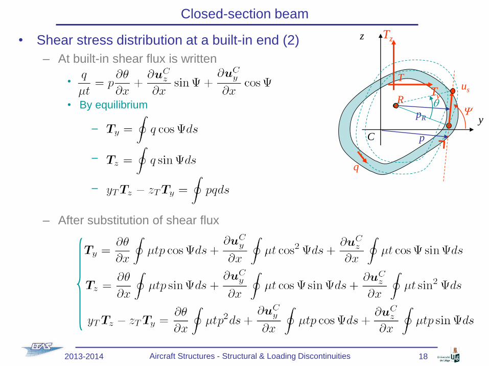
• Shear stress distribution at a built-in end (2)
– At built-in shear flux is written
•
• By equilibrium
–
–
–
– After substitution of shear flux
Closed-section beam
y
z
R
C p
pRY
us
q
q
T
Tz
Ty
2013-2014 Aircraft Structures - Structural & Loading Discontinuities 18

• Shear stress distribution at a built-in end (3)
– New system of 3 equations and 3 unknowns
• Solution of the system: , &
– This solution is then substituted into
• Shear flow and shear stress are then defined
• Remains true for any choice of C as long as p is
computed from there
Closed-section beam
y
z
R
C p
pRY
us
q
q
T
Tz
Ty
2013-2014 Aircraft Structures - Structural & Loading Discontinuities 19

• Example
– Built-in end
• Section with constant shear modulus
– Shear stress distribution?
– Center of twist?
Closed-section beam
Wall Length (m) Thickness (mm)
AB 0.375 1.6
BC 0.500 1.0
CD 0.125 1.2
DA 1.0
y’T =
0.1 m
A
B
C
D
z’
y’
Tz = 22 kN
2013-2014 Aircraft Structures - Structural & Loading Discontinuities 20
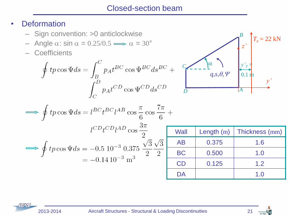
• Deformation
– Sign convention: >0 anticlockwise
– Angle a: sin a = 0.25/0.5 a = 30°
– Coefficients
Closed-section beam
Wall Length (m) Thickness (mm)
AB 0.375 1.6
BC 0.500 1.0
CD 0.125 1.2
DA 1.0
y’T =
0.1 m
A
B
C
D
z’
y’
Tz = 22 kN
q,s,q,Y
a
2013-2014 Aircraft Structures - Structural & Loading Discontinuities 21

• Deformation (2)
– Coefficients (2)
Closed-section beam
Wall Length (m) Thickness (mm)
AB 0.375 1.6
BC 0.500 1.0
CD 0.125 1.2
DA 1.0
y’T =
0.1 m
A
B
C
D
z’
y’
Tz = 22 kN
q,s,q,Y
a
2013-2014 Aircraft Structures - Structural & Loading Discontinuities 22

• Deformation (3)
– Coefficients (3)
Closed-section beam
Wall Length (m) Thickness (mm)
AB 0.375 1.6
BC 0.500 1.0
CD 0.125 1.2
DA 1.0
y’T =
0.1 m
A
B
C
D
z’
y’
Tz = 22 kN
q,s,q,Y
a
2013-2014 Aircraft Structures - Structural & Loading Discontinuities 23

• Deformation (4)
– Coefficients (4)
Closed-section beam
Wall Length (m) Thickness (mm)
AB 0.375 1.6
BC 0.500 1.0
CD 0.125 1.2
DA 1.0
y’T =
0.1 m
A
B
C
D
z’
y’
Tz = 22 kN
q,s,q,Y
a
2013-2014 Aircraft Structures - Structural & Loading Discontinuities 24

• Deformation (5)
– Coefficients (5)
Closed-section beam
Wall Length (m) Thickness (mm)
AB 0.375 1.6
BC 0.500 1.0
CD 0.125 1.2
DA 1.0
y’T =
0.1 m
A
B
C
D
z’
y’
Tz = 22 kN
q,s,q,Y
a
2013-2014 Aircraft Structures - Structural & Loading Discontinuities 25

• Deformation (6)
– Coefficients (6)
Closed-section beam
Wall Length (m) Thickness (mm)
AB 0.375 1.6
BC 0.500 1.0
CD 0.125 1.2
DA 1.0
y’T =
0.1 m
A
B
C
D
z’
y’
Tz = 22 kN
q,s,q,Y
a
2013-2014 Aircraft Structures - Structural & Loading Discontinuities 26

• Deformation (7)
– System with origin of the axis at point A (C A)
•
•
•
Closed-section beam
2013-2014 Aircraft Structures - Structural & Loading Discontinuities 27

• Deformation (8)
– System (2)
•
•
•
Closed-section beam
2013-2014 Aircraft Structures - Structural & Loading Discontinuities 28

• Shear flux
–
– Wall AB
– Wall DA
Closed-section beam
Wall Length (m) Thickness (mm)
AB 0.375 1.6
BC 0.500 1.0
CD 0.125 1.2
DA 1.0
y’T =
0.1 m
A
B
C
D
z’
y’
Tz = 22 kN
q,s,q,Y
a
2013-2014 Aircraft Structures - Structural & Loading Discontinuities 29

• Shear flux (2)
–
– Wall BC
Closed-section beam
Wall Length (m) Thickness (mm)
AB 0.375 1.6
BC 0.500 1.0
CD 0.125 1.2
DA 1.0
y’T =
0.1 m
A
B
C
D
z’
y’
Tz = 22 kN
q,s,q,Y
a
2013-2014 Aircraft Structures - Structural & Loading Discontinuities 30

• Shear flux (3)
–
– Wall CD
Closed-section beam
Wall Length (m) Thickness (mm)
AB 0.375 1.6
BC 0.500 1.0
CD 0.125 1.2
DA 1.0
y’T =
0.1 m
A
B
C
D
z’
y’
Tz = 22 kN
q,s,q,Y
a
2013-2014 Aircraft Structures - Structural & Loading Discontinuities 31

• Center of twist
– System linked to point A
• Remarks
– The center of twist
• Depends on loading (yT and T)
• Does not correspond to the center of shear
• Due to the warping constrain
– Shear flux discontinuitiy at corners
• Requires booms in order of avoiding
stress concentrations
Closed-section beam
Wall Length (m) Thickness (mm)
AB 0.375 1.6
BC 0.500 1.0
CD 0.125 1.2
DA 1.0
y’T =
0.1 m
A
B
C
D
z’
y’
Tz = 22 kN
q,s,q,Y
a
2013-2014 Aircraft Structures - Structural & Loading Discontinuities 32

• Thin walled rectangular-section beam subjected to torsion
– In the case of free warping, we found
•
•
– If warping is constrained (built-in end)
• Direct stress are introduced
• Different shear stress distribution
Closed-section beam
z
y
tb
A
b
B
C
Cth
h
D
Mx s
z
yC
Mx
x
2013-2014 Aircraft Structures - Structural & Loading Discontinuities 33

• Thin walled rectangular-section beam subjected to torsion (2)
– Idealization
• Warping to be suppressed is linear & symmetrical
Direct stress also linear & symmetrical
• Idealization
– Four identical booms
carrying direct stress only
– Panels carry shear flux only
Closed-section beam
b
sxx1
sxx2
A1 A2
y
z
x
tD
b
y
z
xsxx
1sxx
2
z
y
tb
A
b
B
C
Cth
h
D
Mx s
2013-2014 Aircraft Structures - Structural & Loading Discontinuities 34

• Thin walled rectangular-section beam subjected to torsion (3)
– Warping at a given section
• Shearing (see beam lecture)
• Warping
– If uxm is the maximum warping
– On webs
– On covers
Closed-section beam
s
x
dx
dsdus
dux
n
z
y
Mxx
L
b
h
dx
qb
qh
uxm
2013-2014 Aircraft Structures - Structural & Loading Discontinuities 35
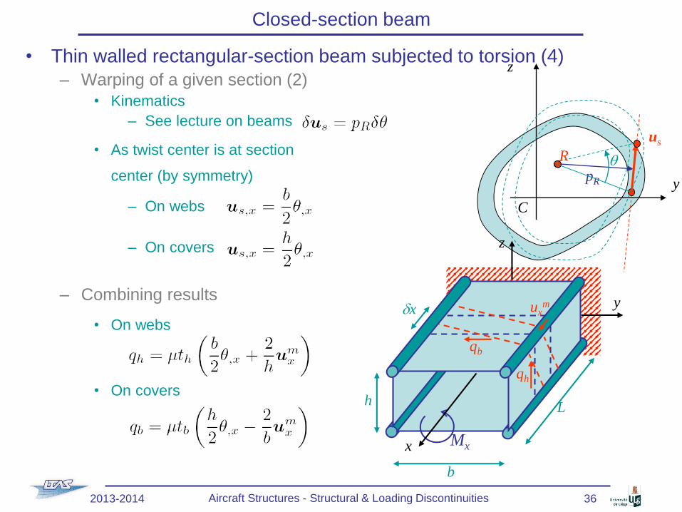
• Thin walled rectangular-section beam subjected to torsion (4)
– Warping of a given section (2)
• Kinematics
– See lecture on beams
• As twist center is at section
center (by symmetry)
– On webs
– On covers
– Combining results
• On webs
• On covers
Closed-section beam
y
z
R
C
pR
us
q
z
y
Mxx
L
b
h
dx
qb
qh
uxm
2013-2014 Aircraft Structures - Structural & Loading Discontinuities 36

• Thin walled rectangular-section beam subjected to torsion (5)
– Torque
• From shear flow qh & qb
• Using
– Twist rate is directly obtained
Closed-section beam
z
y
Mxx
L
b
h
dx
qb
qh
2013-2014 Aircraft Structures - Structural & Loading Discontinuities 37

• Thin walled rectangular-section beam subjected to torsion (6)
– Shear flows
• From shear flow qh & qb
• Using
– Missing balance equation is obtained from boom balance
Closed-section beam
z
y
Mxx
L
b
h
dx
qb
qh
2013-2014 Aircraft Structures - Structural & Loading Discontinuities 38

• Thin walled rectangular-section beam subjected to torsion (7)
– Boom (of section A) balance equation
•
• As boom carries direct stress only
• With
Closed-section beam
dx
qi
sxx+∂xsxxdx
sxx
y
z
x
qb
qh
2013-2014 Aircraft Structures - Structural & Loading Discontinuities 39

• Thin walled rectangular-section beam subjected to torsion (8)
– Differential equation
• with
– Solution
• General form
• Boundary conditions at x = 0 (constraint warping)
• Boundary conditions at x = L (free edge)
• Final form
Closed-section beam
2013-2014 Aircraft Structures - Structural & Loading Discontinuities 40

• Thin walled rectangular-section beam subjected to torsion (9)
– Warping
• At free end:
• To be compared with the warping of the free-free beam
–
– Same for L → ∞
Closed-section beam
z
y
Mxx
L
b
h
dx
qb
qh
uxm
2013-2014 Aircraft Structures - Structural & Loading Discontinuities 41

• Thin walled rectangular-section beam subjected to torsion (10)
– Direct stress in booms
– Direct load in booms
Closed-section beam
z
y
Mxx
L
b
h
dx
qb
qh
uxm
2013-2014 Aircraft Structures - Structural & Loading Discontinuities 42

• Thin walled rectangular-section beam subjected to torsion (11)
– Shear flow
• Using
• The shear flows becomes
Closed-section beam
z
y
Mxx
L
b
h
dx
qb
qh
uxm
2013-2014 Aircraft Structures - Structural & Loading Discontinuities 43

• Thin walled rectangular-section beam subjected to torsion (12)
– Shear stress
Closed-section beam
x/L 1
covers
webs
z
y
Mxx
L
b
h
dx
qb
qh
uxm
2013-2014 Aircraft Structures - Structural & Loading Discontinuities 44

• Thin walled rectangular-section beam subjected to torsion (13)
– Rate of twist
• Using
• The rate of twist becomes
– To be compared with the unconstraint
theory
•
• Constraint reduces the twist rate
Closed-section beam
z
y
Mxx
L
b
h
dx
qb
qh
uxm
2013-2014 Aircraft Structures - Structural & Loading Discontinuities 45

• Problem of axial constraint
– In previous example the twist center was known by symmetry
– In the general case
• Twist center differs from shear center due to axial constraint
• Proceed by increment of DL
– Shear stress distribution calculated at the built-in section
» As in first example
» Allows determination of the twist center AT THAT SECTION
– Use the previously developed theory on DL
– New stress distribution on the new section
» New twist center
» …
Closed-section beam
2013-2014 Aircraft Structures - Structural & Loading Discontinuities 46

• Shear lag
– Beam shearing
• Shear strain in cross-section
• Deformation of cross-section
• Elementary theory of bending
– For pure bending
– Not valid anymore due to
cross section deformation
• New distribution of direct stress
– For wings
• Wide & thin walled beam
• Shear distortion of upper and
lower skins causes redistribution
of stress in the stringers
Closed-section beam
2013-2014 Aircraft Structures - Structural & Loading Discontinuities 47

• Example
– Assumptions
• Doubly symmetrical 6-boom beam
• Shear load trough shear center No twist No warping due to twist
• Uniform panel thickness t
• Shear loads applied at corner booms
Closed-section beam
z
y
x
L
d
h
Tz/2d
A1 A2A1 qh
qd
Tz/2
2013-2014 Aircraft Structures - Structural & Loading Discontinuities 48

• Shear lag (2)
– For a given section
• Uniform shear flow between booms
• Shear flow in web should balance
the shear load
• Corner booms subjected to opposite
loads P1 , with, by equilibrium
• Equilibrium of central boom
– Due to symmetric distribution
of qd
Closed-section beamz
y
x
L
d
h
Tz/2d
A1 A2A1 qh
qd
Tz/2
qh
P1
P1
P1
P1
dx
qhh
Tz/2
qd qd
P2
qd
2013-2014 Aircraft Structures - Structural & Loading Discontinuities 49
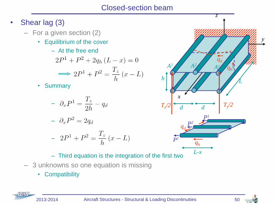
• Shear lag (3)
– For a given section (2)
• Equilibrium of the cover
– At the free end
• Summary
–
–
–
– Third equation is the integration of the first two
– 3 unknowns so one equation is missing
• Compatibility
Closed-section beamz
y
x
L
d
h
Tz/2d
A1 A2A1 qh
qd
Tz/2
qhP1
P2qd
L-x
P1
2013-2014 Aircraft Structures - Structural & Loading Discontinuities 50

• Shear lag (4)
– Deformations of top cover
• As
Closed-section beamz
y
x
L
d
h
Tz/2d
A1 A2A1 qh
qd
Tz/2
d
qh
y
x
d
qh dx
y
x
(1+e1xx)dx
(1+e2xx)dx
gxy
gxy+∂xgxydx
2013-2014 Aircraft Structures - Structural & Loading Discontinuities 51

• Shear lag (5)
– Equations
•
•
•
•
– General solution
•
with
Closed-section beamz
y
x
L
d
h
Tz/2d
A1 A2A1 qh
qd
Tz/2
2013-2014 Aircraft Structures - Structural & Loading Discontinuities 52

• Shear lag (6)
– General solution
•
– Boundary conditions
• Zero axial load at x = L C1 = 0
• Zero shear deformation at x = 0
– As &
– Booms direct loadings
•
•
Closed-section beam
2013-2014 Aircraft Structures - Structural & Loading Discontinuities 53

• Shear lag (7)
– Direct load in top cover
•
•
• Pure bending theory leads to
– Compared to pure bending theory
• Compression in central boom is lower
• Compression in corner boom is higher
Closed-section beamz
y
x
L
d
h
Tz/2d
A1 A2A1 qh
qd
Tz/2
qhP1
P2qd
L-x
P1
2013-2014 Aircraft Structures - Structural & Loading Discontinuities 54
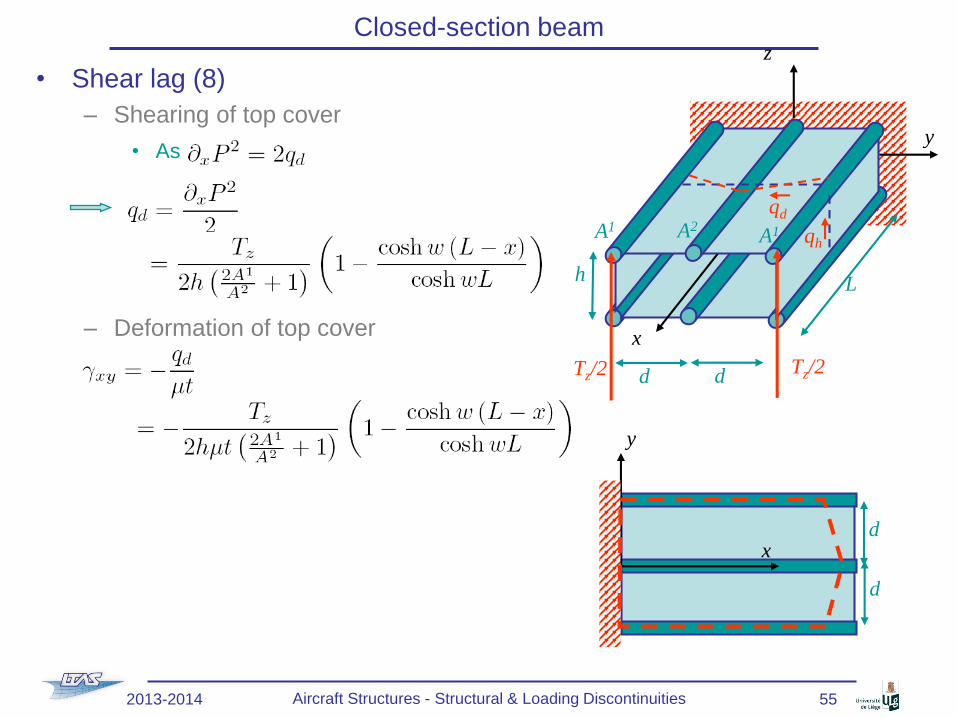
• Shear lag (8)
– Shearing of top cover
• As
– Deformation of top cover
Closed-section beamz
y
x
L
d
h
Tz/2d
A1 A2A1 qh
qd
Tz/2
d
y
x
d
2013-2014 Aircraft Structures - Structural & Loading Discontinuities 55

• Shear lag (9)
– Remark
• The solution depends on BCs
• For a realistic wing structure, intermediate stringers have different BCs
Closed-section beam
d
d
y
x
2013-2014 Aircraft Structures - Structural & Loading Discontinuities 56

• I-section beam subjected to torsion without built-in end
– Reminder
• Shear
–
–
– Or
• Warping
–
– Particular case of the I-Section beam
• There is no shear stress at mid plane of flanges
• They remain rectangular after torsion
Open-section beam
t
t
z
y
C
Mx
t
ns
t
R
pR
us
q
y
z
l2
t2
l1
t1
l3
t3
t
Mx
Mx Mx
2013-2014 Aircraft Structures - Structural & Loading Discontinuities 57

• I-section beam subjected to torsion with built-in end
– Contrarily to the free/free beam
– Presence of the built-end leads to deformation of the flanges
• The beam still twists but with a non-constant twist rate
• Method of solving: Combination of
– Saint-Venant shear stress
– Bending of flanges
Open-section beam
Mx Mx
Mx
2013-2014 Aircraft Structures - Structural & Loading Discontinuities 58

• I-section beam subjected to torsion with built-in end (2)
– Saint-Venant shear stress
•
• Where is not constant
Open-section beam
Mx
2013-2014 Aircraft Structures - Structural & Loading Discontinuities 59

• I-section beam subjected to torsion with built-in end (3)
– Bending of the flanges
• For a given section
– Angle of torsion q
– Lateral displacement of lower flange
»
– Bending moment in lower flange
»
» With
» It has been assumed that
displacement of the flange results
from bending only
– Shearing in the lower flange
»
Open-section beam
h L
qd
Mx
z
y
xbf
y
z
bf
tf
q
Tyf
Tyf
Mfz
h
2013-2014 Aircraft Structures - Structural & Loading Discontinuities 60

• I-section beam subjected to torsion with built-in end (4)
– Bending of the flanges (2)
• For a given section (2)
– Shearing in the lower flange
»
– As shearing in top flange is in
opposite direction, moment due to
bending of the flange becomes
– Total torque on the beam
•
Open-section beam
h L
qd
Mx
z
y
xbf
y
z
bf
tf
q
Tyf
Tyf
Mfz
h
2013-2014 Aircraft Structures - Structural & Loading Discontinuities 61
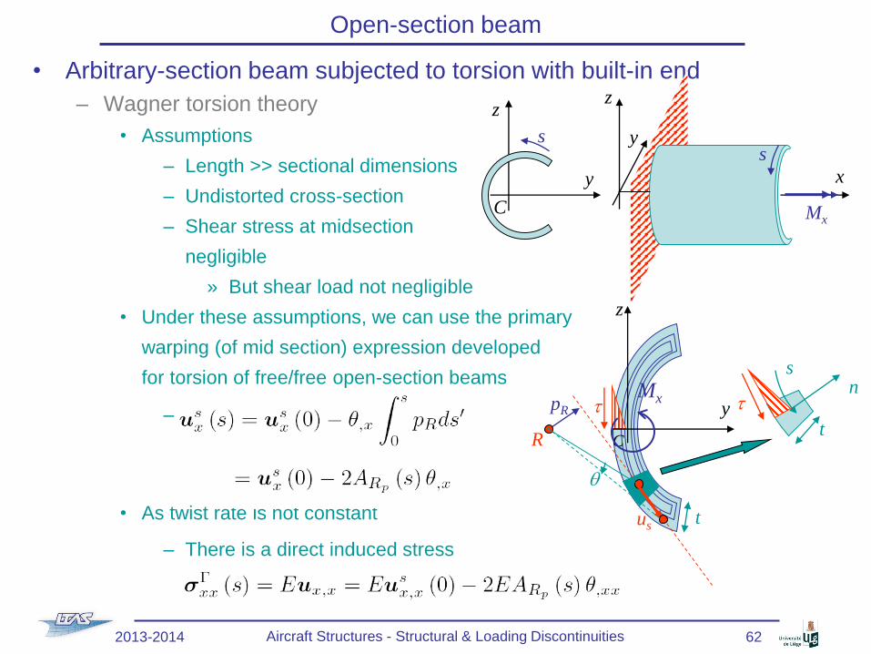
• Arbitrary-section beam subjected to torsion with built-in end
– Wagner torsion theory
• Assumptions
– Length >> sectional dimensions
– Undistorted cross-section
– Shear stress at midsection
negligible
» But shear load not negligible
• Under these assumptions, we can use the primary
warping (of mid section) expression developed
for torsion of free/free open-section beams
–
• As twist rate is not constant
– There is a direct induced stress
Open-section beam
y
z
C
s
x
z
ys
Mx
t
t
z
y
C
Mx
t
ns
t
R
pR
us
q
2013-2014 Aircraft Structures - Structural & Loading Discontinuities 62

• Arbitrary-section beam subjected to torsion with built-in end (2)
– Wagner torsion theory (2)
• Direct stress resulting from primary warping
–
• As only a torsion couple is applied
– Integrating on the whole section C x t
should lead to 0
Open-section beam
x
z
ys
Mx
2013-2014 Aircraft Structures - Structural & Loading Discontinuities 63

• Arbitrary-section beam subjected to torsion with built-in end (3)
– Wagner torsion theory (3)
• Direct stress resulting from primary warping (2)
–
• As only a torsion couple is applied (2)
–
• Direct stress is equilibrated by shear flow
– See lecture on beams
– In this case
Open-section beam
q + ∂sq ds
s
x
dx
ds
q + ∂xq dx
ss
ss + ∂sss ds
sxx + ∂xsxx dx
sxx
x
z
ys
Mx
2013-2014 Aircraft Structures - Structural & Loading Discontinuities 64

• Arbitrary-section beam subjected to torsion with built-in end (4)
– Wagner torsion theory (4)
• Equations
–
–
–
• As for s = 0 (free edge) q(0) = 0
–
Open-section beam
x
z
ys
Mx
2013-2014 Aircraft Structures - Structural & Loading Discontinuities 65

• Arbitrary-section beam subjected to torsion with built-in end (5)
– Wagner torsion theory (5)
• Torque
–
– With
Open-section beam
t
t
z
y
C
Mx
t
ns
t
R
pR
us
q
2013-2014 Aircraft Structures - Structural & Loading Discontinuities 66

• Arbitrary-section beam subjected to torsion with built-in end (6)
– Wagner torsion theory (6)
• Torque (2)
• Using the second term becomes
– For s = 0, ARp = 0
– For s = L, as the edge is free, there is no shear flux
– Using these two boundary conditions, second term is rewritten
Open-section beam
2013-2014 Aircraft Structures - Structural & Loading Discontinuities 67

• Arbitrary-section beam subjected to torsion with built-in end (7)
– Wagner torsion theory (7)
• Torque (3)
• Using the integral of first term becomes
• As for s = 0, ARp = 0, and using
• The final expression reads
Open-section beam
2013-2014 Aircraft Structures - Structural & Loading Discontinuities 68

• Arbitrary-section beam subjected to torsion with built-in end (8)
– General expression for torque
•
• With
– Case of the I-section beam
• Center of twist is the center of symmetry C
• For the web: ARp(s) = 0 no contribution to CG
• For lower flange
• For the I-section
Open-section beam
y
z
bf
tf
Mx
hC
s
2013-2014 Aircraft Structures - Structural & Loading Discontinuities 69

• Arbitrary-section beam subjected to torsion with built-in end (9)
– Case of the I-section beam (2)
• Expression
– With
• To be compared with
Open-section beam
y
z
bf
tf
q
Tyf
Tyf
Mfz
h
2013-2014 Aircraft Structures - Structural & Loading Discontinuities 70

• Idealized beam subjected to torsion with built-in end
– For idealized sections with booms
• In expression
• The direct stress is carried out by
– tdirect &
– Booms of section Ai
Open-section beam
y
z
x
dx
2013-2014 Aircraft Structures - Structural & Loading Discontinuities 71

• Applications of beam subjected to torsion with built-in end
– Solution for pure torque
•
with
• Solution
• Boundary conditions
– At built-in end x = 0: No warping, and as
– At free end x = L: no direct load,
and as
Open-section beam
x
z
ys
Mx
2013-2014 Aircraft Structures - Structural & Loading Discontinuities 72

• Applications of beam subjected to torsion with built-in end (2)
– Solution for pure torque (2)
• Twist rate
Open-section beam
x
z
ys
Mx
x/L 1
1
Built-end
Free/free end
2013-2014 Aircraft Structures - Structural & Loading Discontinuities 73

• Applications of beam subjected to torsion with built-in end (3)
– Solution for pure torque (3)
• Angle of twist
– As
– Boundary condition at built end x = 0: No twist
• At free end
Open-section beam
x
z
ys
Mx
Reduction compared to free-
free case
2013-2014 Aircraft Structures - Structural & Loading Discontinuities 74

• Applications of beam subjected to torsion with built-in end (4)
– Distributed torque loading mx
• Two contributions to torque
–
• Balance equation
• As
• To be solved with adequate boundary conditions
– Built-in end: q = 0 & q,x = 0 (no warping)
– Free end: q,xx = 0 (no direct stress) & No torque at free end
Open-section beam
x
z
ymx
Mx+∂xMx dx
dx
Mx
2013-2014 Aircraft Structures - Structural & Loading Discontinuities 75

• Remark
– We have studied
• Axial loading resulting from torsion
• A similar theory can be derived to deduce torsion resulting from axial loading
Open-section beam
2013-2014 Aircraft Structures - Structural & Loading Discontinuities 76

References
• Lecture notes
– Aircraft Structures for engineering students, T. H. G. Megson, Butterworth-
Heinemann, An imprint of Elsevier Science, 2003, ISBN 0 340 70588 4
• Other references
– Books
• Mécanique des matériaux, C. Massonet & S. Cescotto, De boek Université, 1994,
ISBN 2-8041-2021-X
2013-2014 Aircraft Structures - Structural & Loading Discontinuities 77