aircrew training manual cargo helicopter, ch-47d...
TRANSCRIPT
TC 1-240
AIRCREW TRAINING MANUAL CARGO HELICOPTER, CH-47D
SEPTEMBER 2005 DISTRIBUTION RESTRICTION: Approved for public release; distribution is unlimited.
HEADQUARTERS DEPARTMENT OF THE ARMY

This publication is available at Army Knowledge Online (www.us.army.mil) and General Dennis J. Reimer Training and Doctrine
Digital Library at (http://www.train.army.mil).

*TC 1-240
Distribution Restriction: Approved for public release; distribution is unlimited.
*This publication supersedes TC 1-216, 8 October 1992.
i
AIRCREW TRAINING MANUAL CARGO HELICOPTER, CH-47
Contents Page
PREFACE ..............................................................................................................v Chapter 1 Introduction....................................................................................................... 1-1
1-1. Crew Station Designation........................................................................... 1-1 1-2. Symbol Usage and Word Distinctions........................................................ 1-1
Chapter 2 Training.............................................................................................................. 2-1 2-1. Qualification Training.................................................................................. 2-1 2-2. Refresher Training...................................................................................... 2-2 2-3. Mission Training ......................................................................................... 2-5 2-4. Continuation Training ................................................................................. 2-7 2-5. Task List ..................................................................................................... 2-8 2-6. Currency Requirements ........................................................................... 2-12 2-7. Nuclear, Biological, and Chemical Training ............................................. 2-13
Chapter 3 Evaluations ....................................................................................................... 3-1 3-1. Evaluation Principles .................................................................................. 3-1 3-2. Grading Considerations ............................................................................. 3-2 3-3. Crewmember Evaluation............................................................................ 3-2 3-4. Evaluation Sequence ................................................................................. 3-4 3-5. Additional Evaluations ................................................................................ 3-8
Chapter 4 Crewmember Task ........................................................................................... 4-1 4-1. Task Contents ............................................................................................ 4-1 4-2. Tasks .......................................................................................................... 4-6
Chapter 5 Maintenance Test Pilot Tasks ......................................................................... 5-1 5-1. Task Contents ............................................................................................ 5-1 5-2. Tasks .......................................................................................................... 5-4
Training Circular No. TC 1-240
Headquarters Department of the Army
Washington, DC, 12 September 2005
TC 1-240
ii TC 1-240 12 September 2005
Chapter 6 Crew Coordination............................................................................................6-1 6-1. Crew Coordination Background..................................................................6-1 6-2. Crew Coordination Elements ......................................................................6-1 6-3. Crew Coordination Basic Qualities .............................................................6-2 6-4. Crew Coordination Objectives ....................................................................6-6 6-5. Standard Crew Terminology .......................................................................6-6
Appendix A Nonrated Crewmember and Nonrated Trainer Training and Qualification ..................................................................................................... A-1
Appendix B Heads-Up Display............................................................................................. B-1 Appendix C T55-L-712 and T55-GA-714 Qualification Training ....................................... C-1 Appendix D Instructor Pilot Supplemental Information.................................................... D-1 Glossary .............................................................................................. Glossary-1 References ...................................................................................... References-1 Index........................................................................................................... Index-1
Tasks Task 1000 Participate in a crew mission briefing .................................................................4-7 Task 1004 Plan a visual flight rules flight............................................................................4-10 Task 1006 Plan an instrument flight rules flight ..................................................................4-12 Task 1010 Prepare a performance planning card ..............................................................4-14 Task 1012 Verify aircraft weight and balance.....................................................................4-26 Task 1014 Operate aviation life support equipment ...........................................................4-27 Task 1016 Perform internal load operations.......................................................................4-28 Task 1022 Perform preflight inspection ..............................................................................4-30 Task 1024 Perform before starting engine through before leaving helicopter checks .......4-31 Task 1026 Maintain airspace surveillance..........................................................................4-33 Task 1027 Perform health indicator test/power assurance test check...............................4-35 Task 1028 Perform hover power check..............................................................................4-37 Task 1032 Perform radio communication procedures........................................................4-39 Task 1034 Perform ground taxi ..........................................................................................4-41 Task 1038 Perform hovering flight......................................................................................4-44 Task 1040 Perform visual meteorological conditions takeoff .............................................4-47 Task 1042 Perform cruise check procedures .....................................................................4-50 Task 1044 Navigate by pilotage and dead reckoning.........................................................4-54 Task 1046 Perform electronically aided navigation ............................................................4-55 Task 1052 Perform visual meteorological conditions flight maneuvers..............................4-56 Task 1058 Perform visual meteorological conditions approach .........................................4-59 Task 1062 Perform slope operations..................................................................................4-63 Task 1063 Perform external load operations......................................................................4-66 Task 1064 Perform a roll on landing...................................................................................4-73 Task 1070 Respond to emergencies ..................................................................................4-75 Task 1094 Perform flight with advanced flight control system-off ......................................4-77
TC 1-240
12 September 2005 TC 1-240 iii
Task 1170 Perform instrument takeoff ............................................................................... 4-78 Task 1172 Perform radio navigation .................................................................................. 4-80 Task 1174 Perform holding procedures ............................................................................. 4-82 Task 1176 Perform nonprecision approach ....................................................................... 4-83 Task 1178 Perform precision approach ............................................................................. 4-85 Task 1180 Perform emergency global positioning system recovery procedure ................ 4-87 Task 1182 Perform unusual attitude recovery ................................................................... 4-89 Task 1184 Respond to inadvertent instrument meteorological conditions ........................ 4-90 Task 1188 Operate aircraft survivability equipment........................................................... 4-92 Task 1190 Perform/identify hand and arm signals............................................................. 4-94 Task 1194 Perform refueling operations ............................................................................ 4-95 Task 1200 Perform nonrated crewmember duties during a maintenance test flight ......... 4-97 Task 1202 Perform auxiliary power unit operations (NCM only) ....................................... 4-99 Task 1262 Participate in a crew level after-action review ................................................ 4-101 Task 1413 Perform actions on contact............................................................................. 4-103 Task 1474 Respond to night vision goggles failure ......................................................... 4-107 Task 2010 Perform multi-aircraft operations .................................................................... 4-108 Task 2012 Perform tactical flight mission planning.......................................................... 4-110 Task 2014 Perform electronic countermeasures/electronic counter-countermeasures
procedures...................................................................................................... 4-112 Task 2022 Transmit tactical reports ................................................................................. 4-114 Task 2024 Perform terrain flight navigation ..................................................................... 4-115 Task 2026 Perform terrain flight ....................................................................................... 4-117 Task 2034 Perform masking and unmasking................................................................... 4-119 Task 2036 Perform terrain flight deceleration .................................................................. 4-121 Task 2050 Develop an emergency GPS recovery procedure ......................................... 4-122 Task 2052 Perform water bucket operations ................................................................... 4-129 Task 2054 Perform fast-rope insertion and extraction ..................................................... 4-135 Task 2056 Perform rappelling operations ........................................................................ 4-138 Task 2058 Perform special patrol infiltration/exfiltration .................................................. 4-141 Task 2059 Perform rescue-hoist/winch operations.......................................................... 4-144 Task 2064 Perform paradrop operations ......................................................................... 4-148 Task 2066 Perform extended range fuel system procedures .......................................... 4-150 Task 2068 Perform shipboard operations ........................................................................ 4-152 Task 2074 Perform forward arming and refueling point operations................................. 4-155 Task 2076 Perform caving ladder operations .................................................................. 4-158 Task 2078 Perform helocast/soft duck operations........................................................... 4-161 Task 2079 Perform amphibious operations ..................................................................... 4-165 Task 2086 Operate night vision goggles with the AN/AVS-7 (aviation night vision imaging
system heads-up display) attached................................................................ 4-168 Task 2112 Operate armament subsystem....................................................................... 4-169 Task 2125 Perform pinnacle and ridgeline operations..................................................... 4-171 Task 2127 Perform combat maneuvering flight ............................................................... 4-173 Task 4000 Perform prior to maintenance test flight checks ................................................. 5-5 Task 4081 Perform before starting engine checks .............................................................. 5-6 Task 4088 Perform starting engine checks.......................................................................... 5-7 Task 4110 Perform engine runup checks .......................................................................... 5-10

TC 1-240
iv TC 1-240 12 September 2005
Task 4112 Perform taxi checks ..........................................................................................5-11 Task 4113 Perform before hover checks............................................................................5-12 Task 4156 Perform hover checks .......................................................................................5-13 Task 4193 Perform in-flight checks ....................................................................................5-14 Task 4236 Perform autorotation revolutions per minute check ..........................................5-15 Task 4259 Perform maximum continuous power check/perform maximum power
check 714..........................................................................................................5-17 Task 4260 Perform turbine engine analysis check 712......................................................5-18 Task 4262 Perform communication and navigation equipment checks .............................5-20 Task 4276 Perform special equipment or detailed procedures checks..............................5-21 Task 4284 Perform after landing through engine shutdown checks ..................................5-22
Figures Figure 4-1. Example of an aircrew briefing checklist ............................................................. 4-8 Figure 4-2. Example of a nonrated crew briefing checklist.................................................... 4-9 Figure 4-3. Performance planning card ............................................................................... 4-15 Figure 4-4. Example of a crew briefing checklist for external load procedures................... 4-68 Figure 4-5. Suggested crew-level after-action review checklist format ............................. 4-102 Figure 4-6. Sample of an emergency GPS recovery procedure diagram ......................... 4-127 Figure 4-7. Water bucket procedure guide ........................................................................ 4-133 Figure 4-8. Example of a fast-rope operations checklist ................................................... 4-137
Tables Table 2-1. Refresher flight training guide for rated crewmember .......................................... 2-2 Table 2-2. Refresher flight training guide for nonrated crewmember .................................... 2-3 Table 2-3. Rated crewmember base task list for qualification/refresher training .................. 2-3 Table 2-4. Nonrated crewmember (15U) base task list for qualification/refresher
training................................................................................................................ 2-4 Table 2-5. Rated crewmember/nonrated crewmember mission training task list.................. 2-6 Table 2-6. Rated crewmember task list ................................................................................. 2-9 Table 2-7. Nonrated crewmember (15U) task list................................................................ 2-11 Table 2-8. Maintenance test pilot/maintenance test flight evaluator task list ...................... 2-12 Table 4-1. Effect of height above landing (HAL) surface elevation on visibility
minimums ....................................................................................................... 4-126 Table 4-2. Standard rappelling insertion terminology. ....................................................... 4-140 Table A-1. Flight training for nonrated crewmembers ...........................................................A-3 Table A-2. Recommended flight training sequence...............................................................A-3 Table B-1. Heads-up display training program ......................................................................B-2

12 September 2005 TC 1-240 v
Preface
This aircrew training manual (ATM) standardizes aircrew training programs and flight evaluation procedures. This manual provides specific guidelines for executing CH-47 aircrew training based on FM 7-1. It establishes crewmember qualification, and refresher, mission, and continuation training and evaluation requirements. This manual applies to all CH-47 crewmembers and their commanders.
This is not a stand-alone document; all requirements contained in Army regulations (ARs) and TC 1-210 must be met. This manual is the governing authority for training and flight evaluation purposes only if differences exist between the maneuver descriptions in TM 1-1520-240-10 and this ATM. TM 1-1520-240-10 is the governing authority for operation of the aircraft. Implementation of this manual conforms to AR 95-1 and TC 1-210.
This manual (with applicable ARs and TC 1-210) will help all levels of aviation commanders develop a comprehensive aircrew training program. By using the ATM, commanders ensure individual crewmember and aircrew proficiency is commensurate with the unit’s mission and that aircrews employ standard techniques and procedures.
This manual will be used as a “how to” source for performing crewmember duties. It provides performance standards and evaluation guidelines, so crewmembers know the expected level of performance. Each task has a description of the performance required to meet the standard.
Standardization officers, evaluators, and unit trainers will use this manual and TC 1-210 as the primary tools to develop and implement their aircrew training program (ATP).
This manual applies to the Active Army, the Army National Guard (ARNG), and the U.S. Army Reserve (USAR).
The proponent of this publication is U.S. Army Training and Doctrine Command (TRADOC). Send comments and recommendations on DA Form 2028 (Recommended Changes to Publications and Blank Forms) through the aviation unit commander to Commander, U.S. Army Aviation Center, ATTN: ATZQ-ES (Cargo Section), Building 4503 Kingsman Avenue, Fort Rucker, AL 36362-5263. Recommended changes may also be e-mailed to [email protected].
This publication implements portions of standardization agreement (STANAG) 3114 (edition seven).
Unless this publication states otherwise, masculine nouns and pronouns do not refer exclusively to men.
This publication was reviewed for operations security considerations.

This page intentionally left blank.

12 September 2005 TC 1-240 1-1
Chapter 1
Introduction
This ATM describes training requirements for crewmembers. It will be used with AR 95-1, AR 600-105, AR 600-106, NGR (AR) 95-210, TC 1-210, and other applicable publications. The tasks in this ATM enhance training in individual and aircrew proficiency. The training focuses on accomplishing tasks that support the unit's mission. The scope and level of training to be achieved, individually by crewmembers and collectively by aircrews, is dictated by the mission-essential task list (METL). Commanders must ensure aircrews are proficient in METL.
1-1. CREW STATION DESIGNATION. The commander designates a crew station(s) for each crewmember. The commander’s task list must clearly indicate all crew station designations. Training and proficiency sustainment for rated crewmembers is required in each designated crew station with access to the flight controls. Standardization instructor pilots (SPs), instructor pilots (IPs), Instrument Examiners (IEs), and aviators designated to fly from both pilot seats are evaluated, in each seat, during annual proficiency and readiness test (APART) evaluations. Maintenance test pilot examiners (MEs) and maintenance pilots (MPs) will follow chapter 5 for crew station requirements and evaluations. This does not mean that all tasks must be evaluated in each seat. Sustainment training for nonrated crewmembers (NCM) is required in each designated crew station. NCMs are required to be evaluated from all designated crew stations during the APART, but are not required to be evaluated in all tasks from each station.
1-2. SYMBOL USAGE AND WORD DISTINCTIONS.
a. Symbol usage. The diagonal (/) indicates “and,” “or,” or both. For example, IP/SP may mean IP or SP, or IP and SP. For NCMs, SI/FI may mean SI or FI, or SI and FI.
b. Word distinctions. (1) Warnings, cautions, and notes. These words emphasize important and critical
instructions. (a) A warning indicates an operating procedure or a practice that, if not correctly
followed, could result in personal injury or loss of life. (b) A caution indicates an operating procedure or a practice that, if not strictly
observed, could result in damage to, or destruction, of equipment. (c) A note indicates an operating procedure or condition that is essential to highlight.
(2) Will, must, should, and may. These words distinguish between mandatory, preferred, and acceptable methods of accomplishment.
(a) Will or must indicates a mandatory requirement. (b) Should indicates a preferred, but nonmandatory method of accomplishment. (c) May indicates an acceptable method of accomplishment.
c. Night vision devices. (1) Night vision system (NVS) refers to the night vision system that is attached to the
aircraft and is an integral component of the aircraft. (2) Night vision goggles (NVG) refers to any NVG image intensifier system, for example,
the AN/AVS-6 (aviator’s night vision imaging system [ANVIS]). Note: Night vision devices (NVD) refers to both NVG and NVS.

TC 1-240
1-2 TC 1-240 12 September 2005
d. Personnel terminology. Note: The rated crewmember (RCM) is an aviator. Therefore, the terms “rated crewmember,” “aviator,” and “pilot” are used synonymously.
(1) Pilot (PI). The PI will complete all tasks assigned by the pilot-in-command (PC). (2) Pilot-in-Command (PC). The PC has overall responsibility for the operation of the
aircraft from premission planning to mission complete and assigns duties to the crew, as necessary. Additionally, he is the primary trainer of PIs in the development of experience and judgement.
(3) Unit trainer (UT). The UT is a specialized trainer (RCM or NCM) appointed by the commander to assist with unit training. The UT trains readiness level (RL) 2 crewmembers in mission/additional tasks per the ATM and unit METL. To be qualified as an UT, the crewmember must demonstrate a higher level of knowledge, proficiency and the ability to train other crewmembers in accordance with the IP’s handbook.
(4) Instructor pilot (IP). The IP trains and evaluates RCM and NCM, as directed by the commander. The IP may evaluate an IP/SP during proficiency flight evaluation (PFE) resulting from a lapse in aircraft or NVD currency.
(5) Instrument Examiner (IE). The IE trains and evaluates instrument tasks, as directed by AR 95-1 and local requirements.
(6) Standardization instructor pilot (SP). The SP trains and evaluates RCM and NCM and supervises and maintains the standardization program.
(7) Maintenance test pilot (MP). The MP conducts maintenance test flight procedures in accordance with chapter 5.
(8) Maintenance test pilot evaluator (ME). The ME trains and evaluates MPs and MEs in accordance with chapter 5.
(9) Nonrated crewmember (NCM). The NCM is a nonaviator who performs operation-essential duties aboard an aircraft.
(10) Crew chief (CE). The CE assists the flight engineer (FE) with maintaining his assigned aircraft and performs NCM duties.
(11) Flight engineer (FE). The FE maintains his assigned aircraft and performs NCM duties. He is the supervisor and primary trainer for the CE and mechanics assigned to that aircraft. The commander selects NCMs to perform FE duties based on proficiency and experience.
(12) Nonrated crewmember flight engineer instructor (FI). The nonrated crewmember FI trains and evaluates nonrated crewmembers in aircraft tasks per the ATM and unit METL. To qualify as an FI, the crewmember must meet the requirements of AR 95-1.
(13) Nonrated crewmember standardization instructor (SI). The SI trains and evaluates nonrated crewmembers, FIs, and other SIs. He assists the unit SP with supervising and maintaining the standardization program. To qualify as an SI, the crewmember must meet the requirements of AR 95-1.
Note: Unless otherwise specified, the abbreviation CE in the task descriptions refers to either the crew chief or the flight engineer.
(15) Noncrewmember. These individuals perform duties directly related to the in-flight mission of the aircraft, but not essential to the operation of the aircraft. AR 600-106 lists the categories for noncrewmember positions and the number authorized in each unit. Noncrewmembers may perform CE/FE/UT/FI/SI duties while on noncrewmember flight status, if they are military occupational specialty (MOS) qualified and fully integrated into the commander’s ATP. Additionally, noncrewmembers are trained and designated to perform those duties for NCMs who are unable to fly.

12 September 2005 TC 1-240 2-1
Chapter 2
Training
This chapter describes requirements for qualification, readiness level (RL) progression, mission, and continuation training. Crewmember qualification requirements will be according to AR 95-1, TC 1-210, and this ATM.
2-1. QUALIFICATION TRAINING. Crewmembers complete qualification training by demonstrating proficiency in all tasks required to an SP, IP, ME, SI, or FI, as appropriate. Crewmembers undergoing qualification training in the aircraft must fly with an SP, IP, ME, SI, or FI, as appropriate.
Note: Trainers who are evaluating/training NCMs must be at a station without access to the flight controls.
a. Aircraft qualification. (1) Rated crewmember. Initial qualification training in the CH-47 is conducted at the U.S.
Army Aviation Center (USAAVNC) or at DA-approved training sites, in accordance with a USAAVNC-approved program of instruction (POI).
(2) Nonrated crewmember. MOS qualification is conducted at DA-approved training sites. Aircraft qualification training for NCMs (15U) is conducted at the unit per this ATM (appendix A), ETP 2C-011-0002A, applicable regulations, and the commander’s ATP. The NCMs must complete academic and flight training and pass the required written examinations within 90 consecutive days (Reserve Components—1 year). Appendix A outlines qualification training requirements for SIs, FIs, and NCM UTs.
b. NVG qualification. Initial NVG qualification and aircraft NVG qualification will be in accordance with TC 1-210; the USAAVNC NVG training support package (TSP); and this ATM.
(1) Initial NVG qualification. Initial qualification will be conducted at the U.S. Army Aviation Center or DA-approved training site, according to the USAAVNC approved POI or locally using the USAAVNC NVG ETP. Submit written requests for USAAVNC NVG ETP to the Commander, U.S. Army Aviation Center, ATTN: ATZQ-TDS-O, Fort Rucker, Alabama 36362-5000.
(2) Aircraft NVG qualification. (a) Academic training. The crewmember will receive training and demonstrate a
working knowledge of the topics in paragraph 3-4b (7) and (10). (b) Flight training. The crewmember will receive training and demonstrate
proficiency, from the designated crew station, in all base tasks marked with an X in the NVG column of table 2-3 or table 2-4, as appropriate. The commander may select additional base tasks.
c. Minimum flight hours. There are no minimum flight hour requirements. The qualification is proficiency based, determined by the crewmember’s ability to satisfactorily accomplish the designated tasks.

TC 1-240
2-2 TC 1-240 12 September 2005
d. Additional qualifications. (1) Heads-up display (HUD)—appendix B. (2) T55-L-712/T55-GA-714—appendix C.
2-2. REFRESHER TRAINING. Crewmembers are designated RL3 when they meet the criteria of TC 1-210.
a. Aircraft refresher training. (1) Academic training. The crewmember will receive training and demonstrate a working
knowledge of the topics listed in paragraphs 3-4b(1) through (7) and complete an operator’s manual written examination.
(2) Flight training. The crewmember will receive training from all designated crew station(s). A task that may be performed from either crew station does not need to be evaluated from both stations. Table 2-1 and table 2-2 are guides for developing refresher flight training. Proficiency must be demonstrated in all modes marked with an X in the D, I, and N columns of table 2-3 or table 2-4, as applicable. Actual hours will be based on individual crewmember proficiency. The evaluation may be continuous.
(3) Refresher training as a result of a training or evaluation deficiency. Academic and flight training required as a result of a training deficiency or an unsatisfactory evaluation will consist of the academic training, flight training, and evaluation required to regain proficiency. The evaluation will at a minimum consist of the deficient task(s) and any other tasks selected by the commander or the evaluator. There is no requirement to complete the entire refresher training program outlined in this ATM as a result of a training or evaluation deficiency. The evaluation may be continuous.
b. Night vision goggles refresher training. (1) Academic training. The crewmember will receive training and demonstrate a working
knowledge of the applicable topics in paragraph 3-4b (7) and (10). (2) Flight training. The crewmember will receive training and demonstrate proficiency in
all base tasks marked with an X in the NVG column of table 2-3 or table 2-4, as applicable. The commander may select additional base tasks.
(3) Minimum flight hours. There are no minimum flight hour requirements. The training is proficiency based, determined by the crewmember’s ability to accomplish the designated tasks satisfactorily.
Table 2-1. Refresher flight training guide for rated crewmember
Flight Instruction Hours Day and night base task training 6.0 Flight evaluation 2.0 *Instrument base task training (aircraft/simulator) 8.0 Instrument evaluation 2.0 Total hours 18.0 *Recommend a minimum of 2 hours of instrument base task training be in the aircraft.

Training
12 September 2005 TC 1-240 2-3
Table 2-2. Refresher flight training guide for nonrated crewmember
Flight Instruction Hours Day and night base task training 6.0 Flight evaluation 2.0 Total hours 8.0
Table 2-3. Rated crewmember base task list for qualification/refresher training
Legend D—Tasks that must be performed during day flight. I—Tasks that must be performed during instrument flight. N—Tasks that must be performed during unaided night flight. NVG—Tasks that must be evaluated at night in the aircraft while the RCM is wearing the NVG.
Task Task Title D I N NVG
1000 Participate in a crew mission briefing X X X 1004 Plan a visual flight rules flight X 1006 Plan an instrument flight rules flight X 1010 Prepare a performance planning card X 1012 Verify aircraft weight and balance X 1014 Operate aviation life support equipment X 1016 Perform internal load operations X 1022 Perform preflight inspection X 1024 Perform before starting engine through before leaving helicopter checks X X 1026 Maintain airspace surveillance X X X X 1027 Perform health indicator test/power assurance test check X 1028 Perform hover power check X or X X 1032 Perform radio communication procedures X 1034 Perform ground taxi X X 1038 Perform hovering flight X X X 1040 Perform visual meteorological conditions takeoff X X X 1042 Perform cruise check procedures X X X 1044 Navigate by pilotage and dead reckoning X X 1046 Perform electronically aided navigation X X 1052 Perform visual meteorological conditions flight maneuvers X X X 1058 Perform visual meteorological conditions approach X X X 1062 Perform slope operations X X 1063 Perform external load operations X X 1064 Perform roll on landing X X X 1070 Respond to emergencies X X X X 1094 Perform flight with advanced flight control system-off X X X 1170 Perform instrument takeoff X 1172 Perform radio navigation X

TC 1-240
2-4 TC 1-240 12 September 2005
Table 2-3. Rated crewmember base task list for qualification/refresher training
Legend D—Tasks that must be performed during day flight. I—Tasks that must be performed during instrument flight. N—Tasks that must be performed during unaided night flight. NVG—Tasks that must be evaluated at night in the aircraft while the RCM is wearing the NVG.
Task Task Title D I N NVG
1174 Perform holding procedures X 1176 Perform nonprecision approach X
1178 Perform precision approach X 1180 Perform emergency global positioning system recovery procedure X 1182 Perform unusual attitude recovery X X 1184 Respond to inadvertent instrument meteorological conditions X X X 1188 Operate aircraft survivability equipment X 1190 Perform/identify hand and arm signals X 1194 Perform refueling operations X 1262 Participate in a crew level after-action review X X X X 1413 Perform actions on contact X X 1474 Respond to night vision goggles failure. X
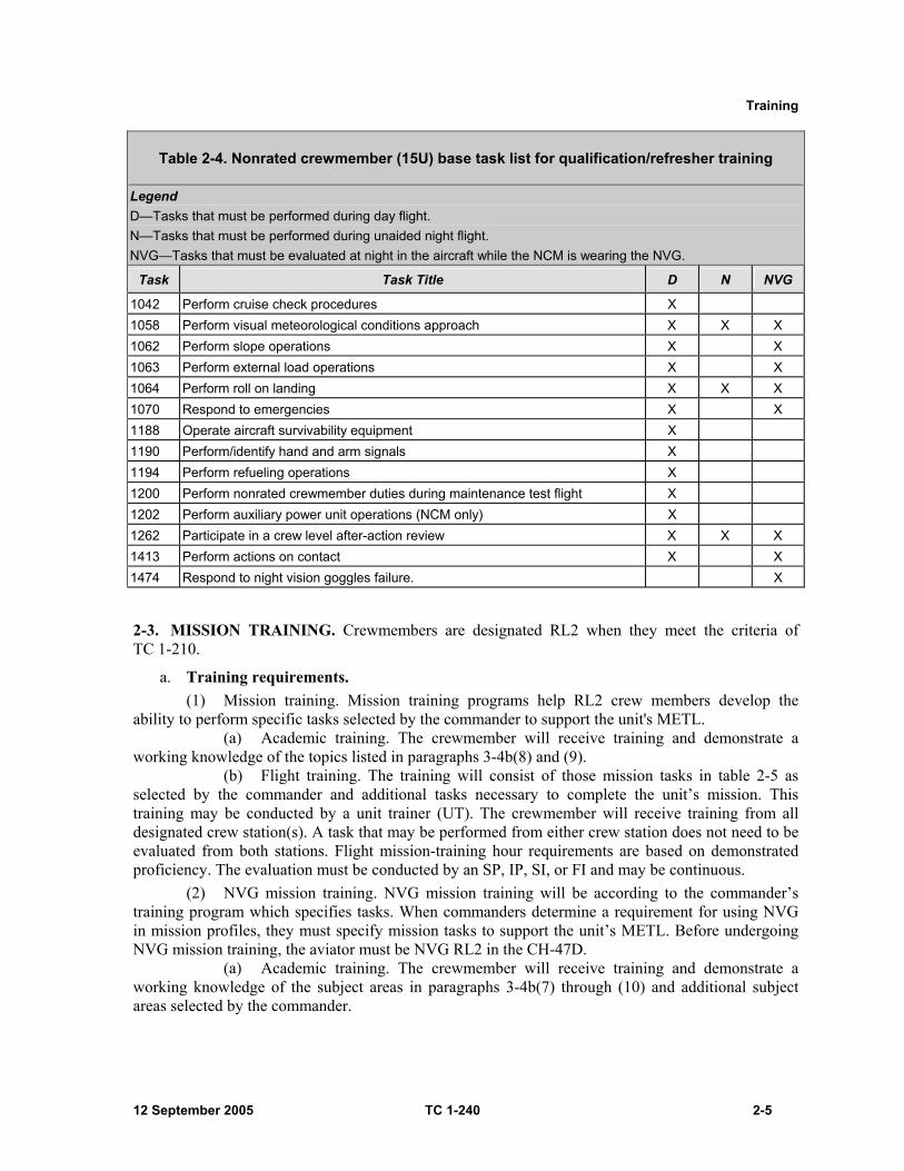
Table 2-4. Nonrated crewmember (15U) base task list for qualification/refresher training
Legend D—Tasks that must be performed during day flight. N—Tasks that must be performed during unaided night flight. NVG—Tasks that must be evaluated at night in the aircraft while the NCM is wearing the NVG.
Task Task Title D N NVG
1000 Participate in a crew mission briefing X X 1012 Verify aircraft weight and balance X 1014 Operate aviation life support equipment X 1016 Perform internal load operations X 1022 Perform preflight inspection X 1024 Perform before starting engine through before leaving helicopter checks X X 1026 Maintain airspace surveillance X X X 1027 Perform health indicator test/power assurance test check X 1028 Perform hover power check X 1032 Perform radio communications procedures X 1034 Perform ground taxi X X 1038 Perform hovering flight X X X 1040 Perform visual meteorological conditions takeoff X X X
Training
12 September 2005 TC 1-240 2-5
Table 2-4. Nonrated crewmember (15U) base task list for qualification/refresher training
Legend D—Tasks that must be performed during day flight. N—Tasks that must be performed during unaided night flight. NVG—Tasks that must be evaluated at night in the aircraft while the NCM is wearing the NVG.
Task Task Title D N NVG
1042 Perform cruise check procedures X 1058 Perform visual meteorological conditions approach X X X 1062 Perform slope operations X X 1063 Perform external load operations X X 1064 Perform roll on landing X X X 1070 Respond to emergencies X X 1188 Operate aircraft survivability equipment X 1190 Perform/identify hand and arm signals X 1194 Perform refueling operations X 1200 Perform nonrated crewmember duties during maintenance test flight X 1202 Perform auxiliary power unit operations (NCM only) X 1262 Participate in a crew level after-action review X X X 1413 Perform actions on contact X X 1474 Respond to night vision goggles failure. X
2-3. MISSION TRAINING. Crewmembers are designated RL2 when they meet the criteria of TC 1-210.
a. Training requirements. (1) Mission training. Mission training programs help RL2 crew members develop the
ability to perform specific tasks selected by the commander to support the unit's METL. (a) Academic training. The crewmember will receive training and demonstrate a
working knowledge of the topics listed in paragraphs 3-4b(8) and (9). (b) Flight training. The training will consist of those mission tasks in table 2-5 as
selected by the commander and additional tasks necessary to complete the unit’s mission. This training may be conducted by a unit trainer (UT). The crewmember will receive training from all designated crew station(s). A task that may be performed from either crew station does not need to be evaluated from both stations. Flight mission-training hour requirements are based on demonstrated proficiency. The evaluation must be conducted by an SP, IP, SI, or FI and may be continuous.
(2) NVG mission training. NVG mission training will be according to the commander’s training program which specifies tasks. When commanders determine a requirement for using NVG in mission profiles, they must specify mission tasks to support the unit’s METL. Before undergoing NVG mission training, the aviator must be NVG RL2 in the CH-47D.
(a) Academic training. The crewmember will receive training and demonstrate a working knowledge of the subject areas in paragraphs 3-4b(7) through (10) and additional subject areas selected by the commander.

TC 1-240
2-6 TC 1-240 12 September 2005
(b) Flight training. The crewmember will receive flight training and demonstrate proficiency in the mission and additional NVG tasks, as specified on the task list for the crewmember’s position.
(3) MP and ME mission training. MPs and MEs should be limited to duties in one primary and one alternate (or additional) aircraft. The MP/ME will complete tasks outlined in table 2-8, page 2-12, and should be required to complete those mission/additional tasks selected by the commander. Crewmembers undergoing training in the aircraft must fly with an ME for maintenance training.
(a) Academic training. The MP will receive training and demonstrate a working knowledge of the topics listed in paragraph 3-4b(11).
(b) Flight training. The MP/ME will receive flight training and demonstrate proficiency in all tasks in table 2-8. See chapter 5 for more guidance.
b. Minimum flight hours. There are no minimum flight hour requirements. The training is proficiency-based, determined by the crewmember’s ability to accomplish the designated tasks satisfactorily. NVG mission training may be included as part of refresher training.
c. Heads-up display qualification. It is recommended that HUD qualification be completed during mission training.
Table 2-5. Rated crewmember/nonrated crewmember mission training task list
Task Task Title 2010 Perform multiaircraft operations 2012 Perform tactical flight mission planning 2014 Perform electronic countermeasures/electronic counter-countermeasures procedures 2022 Transmit tactical reports 2024 Perform terrain flight navigation 2026 Perform terrain flight 2034 Perform masking and unmasking 2036 Perform terrain flight deceleration 2050 Develop an emergency global positioning system recovery procedure 2052 Perform water bucket operations 2054 Perform fast-rope insertion and extraction 2056 Perform rappelling operations 2058 Perform special patrol infiltration/exfiltration 2059 Perform rescue-hoist/winch operations 2064 Perform paradrop operations 2066 Perform extended range fuel system procedures 2068 Perform shipboard operations 2074 Perform forward arming and refueling point operations 2076 Perform caving ladder operations 2078 Perform helocast/soft duck operations 2079 Perform amphibious operations 2086 Operate night vision device with AN/AVS-7 (aviation night imaging system heads-up display) attached 2112 Operate armament subsystem 2125 Perform pinnacle and ridgeline operations 2127 Perform combat maneuvering flight

Training
12 September 2005 TC 1-240 2-7
2-4. CONTINUATION TRAINING. Crewmembers are designated RL1 when they meet the criteria of TC 1-210.
a. Semiannual flying-hour requirements—aircraft. The minimum requirements for crewmembers are as follows:
(1) Rated crewmembers. (a) Flight activity category (FAC) 1—45 hours, which must be flown while
occupying a crew station with access to the flight controls. (b) FAC 2—33 hours, which must be flown while occupying a crew station with
access to the flight controls. (c) FAC 3—no flying-hour requirements.
(2) Nonrated crewmembers. NCM—24 hours, in the aircraft while performing crew duties.
b. Semiannual flying-hour requirements—NVG. The commander will determine semiannual flying-hour requirements for NVGs. The requirement will be tailored to the individual crewmember based on proficiency and experience. RCMs will complete the requirements in the aircraft while occupying a crew station with access to the flight controls. NCMs will complete the requirements while performing crew duties.
Note: UTs and evaluators may credit those hours they fly while performing assigned duties, regardless of their crew station, toward their semiannual flying-hour requirements. c. Annual simulation device flying-hour requirements. All Active and Reserve RCMs
within 200SM of a compatible STFS device will complete the following number of hours in the SFTS. RCMs may apply 12 hours of CH-47FS time toward their semiannual flying-hour requirement. RCMs outside of 200SM refer to AR 95-1. ARNG RCMs refer to NGR 95-1.
(1) FAC 1 – 18 hours annually. (2) FAC 2 – 12 hours annually. (3) FAC 3 – 10 hours semiannually regardless of distance from a CH-47FS.
d. Annual task and iteration requirements. The minimum requirements are as follows: (1) FAC 1 and FAC 2. Each crewmember must perform at least one task iteration annually
in each required flying mode as indicated in table 2-6 or table 2-7, the tasks selected from table 2-5, and additional tasks on the commander’s task list (CTL). One iteration of each task must be performed in the aircraft. Tasks performed at night (or while using NVGs) may be counted for day iterations. The crewmember is responsible for maintaining proficiency in each task. The commander may require additional iterations of specific tasks.
(2) FAC 3. Each crewmember must perform, in the simulator, at least one iteration annually of each task annotated on the CTL. The crewmember is responsible for maintaining proficiency in each task. The commander may require additional iterations of specific tasks.
(3) MPs and MEs. In addition to the required minimum annual tasks and iterations, MPs and MEs will perform a minimum of four iterations of maintenance test flight (MTF) tasks listed in table 2-8, page 2-12, annually. MEs will perform a minimum of two of the four iterations mentioned above from each flight crew station with access to the flight controls.
e. Hood/weather requirements. All aviators will complete hood or weather requirements as determined by the commander. This requirement may be completed in the aircraft or simulator.
2-5. TASK LIST.
a. Performance tasks. For the purpose of clarifying mode and conditions, a performance task is differentiated from a technical task. An ATM performance task is a task that is significantly affected

TC 1-240
2-8 TC 1-240 12 September 2005
by the conditions and the mode of flight and, therefore, the mode and condition under which the task must be performed is specified. For example: visual meteorological conditions (VMC) takeoff, emergency procedure flight, or perform external load operations. These tasks are listed in upper case and bold type.
b. Technical tasks. Technical tasks are those tasks that measure the crewmember’s ability to plan a flight, preflight, participate in crew mission briefing, perform hover power check, and so forth. These tasks are not significantly affected by the mode of flight and may be performed or evaluated in any mode. These tasks are in lower case and plain type.
Note: The requirement to perform instrument tasks in additional aircraft, in category, will be at the discretion of the commander.
Note: RCMs who are required to perform MP or ME duties in the CH-47 as an additional or alternate aircraft will perform four iterations of the required tasks.
c. Base tasks. Table 2-6 and table 2-7 list the RCM and NCM base task requirements.
d. Mission tasks. Table 2-5 lists the RCM and NCM mission tasks. The commander will select mission and additional tasks and iterations that support the unit’s METL and individual proficiency. The commander will determine the evaluation requirements for all mission tasks and modes of flight and annotate the air crewmember’s CTL accordingly.
e. Maintenance test pilot tasks. Refer to chapter 5.
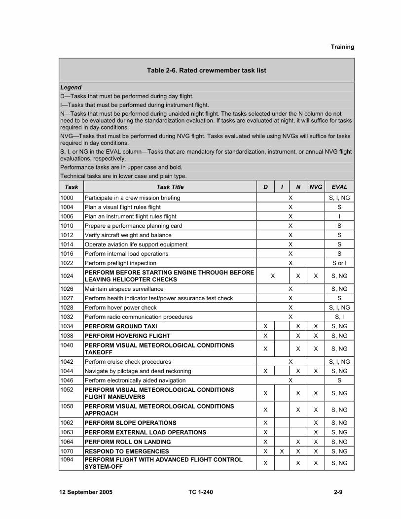
f. Evaluation guidelines. Aviators designated to fly from both pilot seats are evaluated, in each seat, during annual proficiency and readiness test (APART) evaluations. This does not mean that all tasks must be evaluated from each crew station. Sustainment training for nonrated crewmembers (NCM) is required in each designated crew station. NCMs are required to be evaluated from all designated crew stations during the APART, but are not required to be evaluated in all tasks from each station. APART and annual evaluation tasks are designated by an S, I, and/or NG in the EVAL column of table 2-6 and table 2-7. The tasks selected under the N column do not need to be evaluated during the standardization evaluation. Tasks evaluated at night (or while using NVG) will suffice for tasks required in day conditions. Mission tasks will be evaluated during the APART, if the task is on the individual’s CTL and designated with an E. The commander should select mission/additional mission tasks for evaluation, based on the unit’s METL. Refer to chapter 5 for MP/ME APART requirements.
Training
12 September 2005 TC 1-240 2-9
Table 2-6. Rated crewmember task list
Legend D—Tasks that must be performed during day flight. I—Tasks that must be performed during instrument flight. N—Tasks that must be performed during unaided night flight. The tasks selected under the N column do not need to be evaluated during the standardization evaluation. If tasks are evaluated at night, it will suffice for tasks required in day conditions. NVG—Tasks that must be performed during NVG flight. Tasks evaluated while using NVGs will suffice for tasks required in day conditions. S, I, or NG in the EVAL column—Tasks that are mandatory for standardization, instrument, or annual NVG flight evaluations, respectively. Performance tasks are in upper case and bold. Technical tasks are in lower case and plain type.
Task Task Title D I N NVG EVAL
1000 Participate in a crew mission briefing X S, I, NG 1004 Plan a visual flight rules flight X S 1006 Plan an instrument flight rules flight X I 1010 Prepare a performance planning card X S 1012 Verify aircraft weight and balance X S 1014 Operate aviation life support equipment X S 1016 Perform internal load operations X S 1022 Perform preflight inspection X S or I
1024 PERFORM BEFORE STARTING ENGINE THROUGH BEFORE LEAVING HELICOPTER CHECKS X X X S, NG
1026 Maintain airspace surveillance X S, NG 1027 Perform health indicator test/power assurance test check X S 1028 Perform hover power check X S, I, NG 1032 Perform radio communication procedures X S, I 1034 PERFORM GROUND TAXI X X X S, NG 1038 PERFORM HOVERING FLIGHT X X X S, NG 1040 PERFORM VISUAL METEOROLOGICAL CONDITIONS
TAKEOFF X X X S, NG
1042 Perform cruise check procedures X S, I, NG 1044 Navigate by pilotage and dead reckoning X X X S, NG 1046 Perform electronically aided navigation X S 1052 PERFORM VISUAL METEOROLOGICAL CONDITIONS
FLIGHT MANEUVERS X X X S, NG
1058 PERFORM VISUAL METEOROLOGICAL CONDITIONS APPROACH X X X S, NG
1062 PERFORM SLOPE OPERATIONS X X S, NG 1063 PERFORM EXTERNAL LOAD OPERATIONS X X S, NG 1064 PERFORM ROLL ON LANDING X X X S, NG 1070 RESPOND TO EMERGENCIES X X X X S, NG 1094 PERFORM FLIGHT WITH ADVANCED FLIGHT CONTROL
SYSTEM-OFF X X X S, NG
TC 1-240
2-10 TC 1-240 12 September 2005
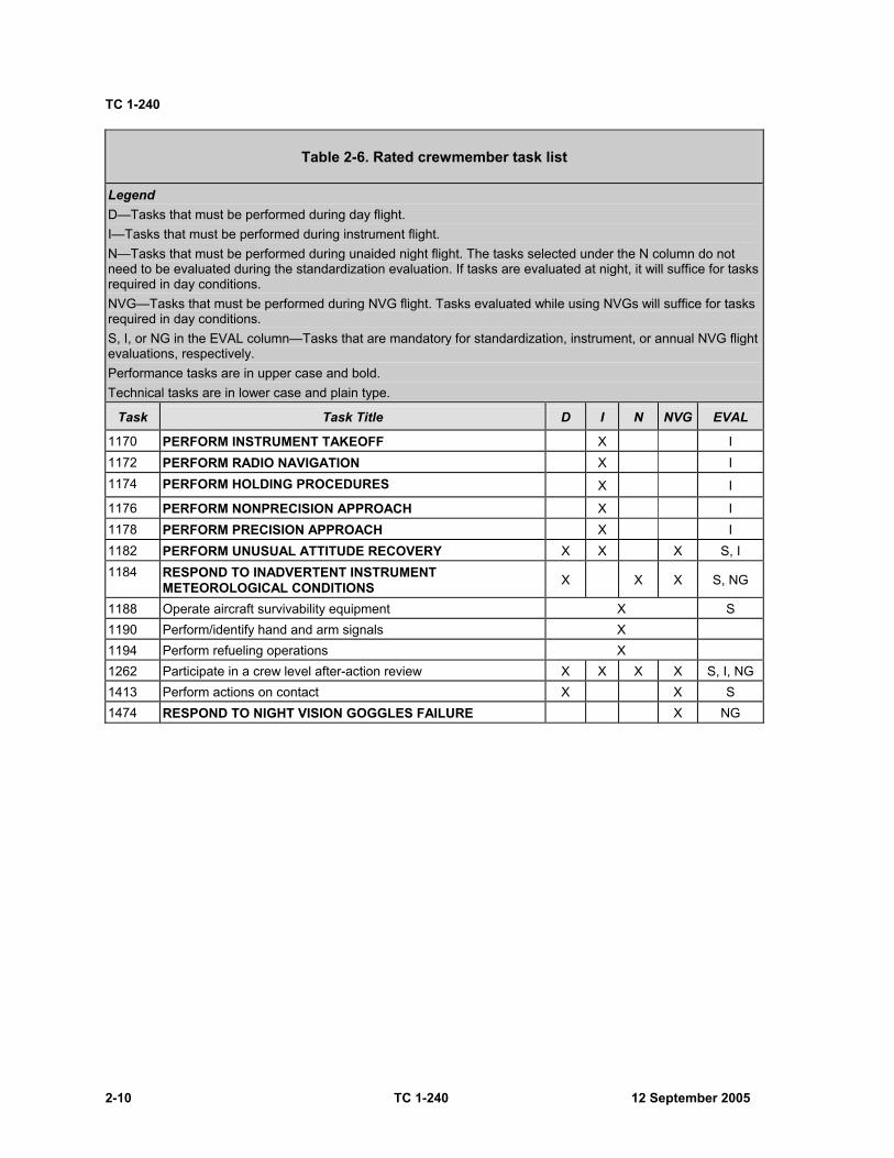
Table 2-6. Rated crewmember task list
Legend D—Tasks that must be performed during day flight. I—Tasks that must be performed during instrument flight. N—Tasks that must be performed during unaided night flight. The tasks selected under the N column do not need to be evaluated during the standardization evaluation. If tasks are evaluated at night, it will suffice for tasks required in day conditions. NVG—Tasks that must be performed during NVG flight. Tasks evaluated while using NVGs will suffice for tasks required in day conditions. S, I, or NG in the EVAL column—Tasks that are mandatory for standardization, instrument, or annual NVG flight evaluations, respectively. Performance tasks are in upper case and bold. Technical tasks are in lower case and plain type.
Task Task Title D I N NVG EVAL
1170 PERFORM INSTRUMENT TAKEOFF X I 1172 PERFORM RADIO NAVIGATION X I 1174 PERFORM HOLDING PROCEDURES X I
1176 PERFORM NONPRECISION APPROACH X I 1178 PERFORM PRECISION APPROACH X I 1182 PERFORM UNUSUAL ATTITUDE RECOVERY X X X S, I 1184 RESPOND TO INADVERTENT INSTRUMENT
METEOROLOGICAL CONDITIONS X X X S, NG
1188 Operate aircraft survivability equipment X S 1190 Perform/identify hand and arm signals X 1194 Perform refueling operations X 1262 Participate in a crew level after-action review X X X X S, I, NG 1413 Perform actions on contact X X S 1474 RESPOND TO NIGHT VISION GOGGLES FAILURE X NG
Training
12 September 2005 TC 1-240 2-11
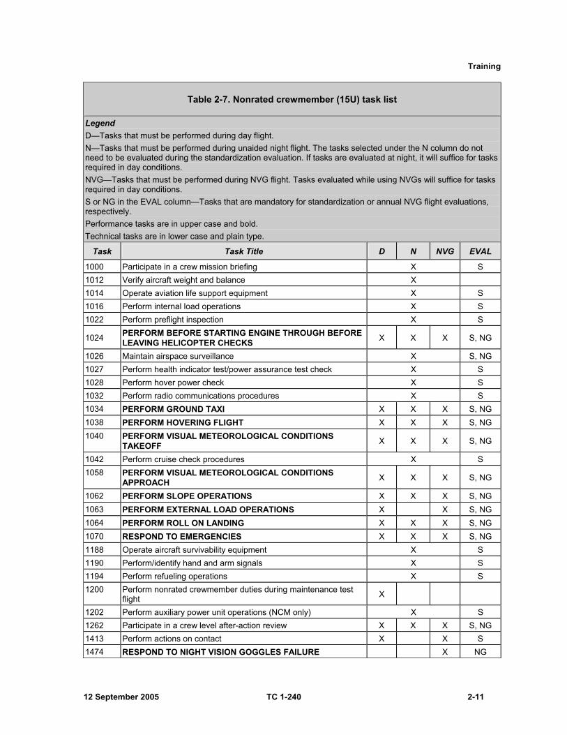
Table 2-7. Nonrated crewmember (15U) task list
Legend D—Tasks that must be performed during day flight. N—Tasks that must be performed during unaided night flight. The tasks selected under the N column do not need to be evaluated during the standardization evaluation. If tasks are evaluated at night, it will suffice for tasks required in day conditions. NVG—Tasks that must be performed during NVG flight. Tasks evaluated while using NVGs will suffice for tasks required in day conditions. S or NG in the EVAL column—Tasks that are mandatory for standardization or annual NVG flight evaluations, respectively. Performance tasks are in upper case and bold. Technical tasks are in lower case and plain type.
Task Task Title D N NVG EVAL
1000 Participate in a crew mission briefing X S 1012 Verify aircraft weight and balance X 1014 Operate aviation life support equipment X S 1016 Perform internal load operations X S 1022 Perform preflight inspection X S
1024 PERFORM BEFORE STARTING ENGINE THROUGH BEFORE LEAVING HELICOPTER CHECKS X X X S, NG
1026 Maintain airspace surveillance X S, NG 1027 Perform health indicator test/power assurance test check X S 1028 Perform hover power check X S 1032 Perform radio communications procedures X S 1034 PERFORM GROUND TAXI X X X S, NG 1038 PERFORM HOVERING FLIGHT X X X S, NG 1040 PERFORM VISUAL METEOROLOGICAL CONDITIONS
TAKEOFF X X X S, NG
1042 Perform cruise check procedures X S 1058 PERFORM VISUAL METEOROLOGICAL CONDITIONS
APPROACH X X X S, NG
1062 PERFORM SLOPE OPERATIONS X X X S, NG 1063 PERFORM EXTERNAL LOAD OPERATIONS X X S, NG 1064 PERFORM ROLL ON LANDING X X X S, NG 1070 RESPOND TO EMERGENCIES X X X S, NG 1188 Operate aircraft survivability equipment X S 1190 Perform/identify hand and arm signals X S 1194 Perform refueling operations X S 1200 Perform nonrated crewmember duties during maintenance test
flight X
1202 Perform auxiliary power unit operations (NCM only) X S 1262 Participate in a crew level after-action review X X X S, NG 1413 Perform actions on contact X X S 1474 RESPOND TO NIGHT VISION GOGGLES FAILURE X NG
TC 1-240
2-12 TC 1-240 12 September 2005
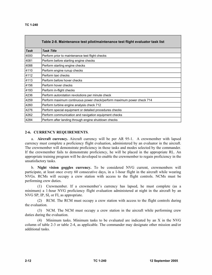
Table 2-8. Maintenance test pilot/maintenance test flight evaluator task list
Task Task Title 4000 Perform prior to maintenance test flight checks 4081 Perform before starting engine checks 4088 Perform starting engine checks 4110 Perform engine runup checks 4112 Perform taxi checks 4113 Perform before hover checks 4156 Perform hover checks 4193 Perform in-flight checks 4236 Perform autorotation revolutions per minute check 4259 Perform maximum continuous power check/perform maximum power check 714 4260 Perform turbine engine analysis check 712 4276 Perform special equipment or detailed procedures checks 4262 Perform communication and navigation equipment checks 4284 Perform after landing through engine shutdown checks
2-6. CURRENCY REQUIREMENTS.
a. Aircraft currency. Aircraft currency will be per AR 95-1. A crewmember with lapsed currency must complete a proficiency flight evaluation, administered by an evaluator in the aircraft. The crewmember will demonstrate proficiency in those tasks and modes selected by the commander. If the crewmember fails to demonstrate proficiency, he will be placed in the appropriate RL. An appropriate training program will be developed to enable the crewmember to regain proficiency in the unsatisfactory tasks.
b. Night vision goggles currency. To be considered NVG current, crewmembers will participate, at least once every 60 consecutive days, in a 1-hour flight in the aircraft while wearing NVGs. RCMs will occupy a crew station with access to the flight controls. NCMs must be performing crew duties.
(1) Crewmember. If a crewmember’s currency has lapsed, he must complete (as a minimum) a 1-hour NVG proficiency flight evaluation administered at night in the aircraft by an NVG SP, IP, SI, or FI, as appropriate.
(2) RCM. The RCM must occupy a crew station with access to the flight controls during the evaluation.
(3) NCM. The NCM must occupy a crew station in the aircraft while performing crew duties during the evaluation.
(4) Minimum tasks. Minimum tasks to be evaluated are indicated by an X in the NVG column of table 2-3 or table 2-4, as applicable. The commander may designate other mission and/or additional tasks.
Training
12 September 2005 TC 1-240 2-13
2-7. NUCLEAR, BIOLOGICAL, AND CHEMICAL TRAINING. In accordance with TC 1-210, crewmembers must wear the complete nuclear, biological, and chemical (NBC) ensemble during NBC training. All NBC training will be performed in the aircraft. NBC training is not required for FAC 3 positions.
a. Rated crewmember tasks. RCMs will receive NBC training in the following tasks. The commander may select other tasks based on the unit mission.
(1) Task 1024, Perform before-starting engine through before leaving helicopter checks. (2) Task 1028, Perform hover power check. (3) Task 1040, Perform visual meteorological conditions takeoff (terrain flight). (4) Task 1058, Perform visual meteorological conditions approach (terrain flight). (5) Task 2026, Perform terrain flight. (6) Task 2036, Perform terrain flight deceleration.
b. Nonrated crewmember tasks. NCMs will receive NBC training in the following base tasks. The commander may select other tasks based on the unit mission.
(1) Task 1024, Perform before-starting engine through before-leaving helicopter checks. (2) Task 1042, Perform cruise check procedures.

This page intentionally left blank.

12 September 2005 TC 1-240 3-1
Chapter 3
Evaluations
This chapter describes evaluation principles and grading considerations. It also contains guidelines for conducting academic and hands-on performance testing. Evaluations are a primary means of assessing flight standardization and crewmember proficiency. Evaluations will be conducted according to AR 95-1, the commander’s ATP, TC 1-210, and this ATM.
3-1. EVALUATION PRINCIPLES. The value of any evaluation depends on adherence to fundamental evaluation principles. These principles are described below.
a. Selection of evaluators. The evaluators must be selected not only for their technical qualifications, but also for their demonstrated performance, objectivity, and ability to observe and to provide constructive comments. These evaluators are the SPs, IPs, IEs, MEs, SIs, and FIs that assist the commander with administering the ATP.
b. Method of evaluation. The method used to conduct the evaluation must be based on uniform and standard objectives. In addition, it must be consistent with the unit's mission and strictly adhere to the appropriate standing operating procedures (SOPs) and regulations. During the evaluation, the evaluator must ensure that a complete evaluation is administered in all areas and refrain from making personal expertise a dominant topic.
c. Participant understanding. All participants must completely understand the purpose of the evaluation.
d. Participant cooperation. Cooperation by all participants is necessary to guarantee the accomplishment of the evaluation objectives. The emphasis is on all the participants, not just the examinee.
e. Identification of training needs. The evaluation must produce specific findings to identify training needs. A crewmember affected by the evaluation needs to know what is being performed correctly and incorrectly and how to make improvements.
f. Purpose of evaluation. An evaluation determines the examinee's ability to perform essential hands-on/academic tasks to prescribed standards. The purpose of the evaluation must be clearly identified to the examinee. Flight evaluations determine the examinee’s ability to exercise crew coordination in completing the tasks.
g. Crew coordination. The guidelines for evaluating crew coordination are based on a subjective analysis of how effectively a crew performs to accomplish a series of tasks. The evaluator must determine how effectively the examinee employs aircrew coordination, as outlined in chapter 6.
h. Evaluator role as crewmember. In all phases of evaluation, the evaluator is expected to perform as an effective crewmember. However, to determine the examinee’s level of proficiency, the evaluator may intentionally perform as an ineffective crewmember. In such cases, a realistic, meaningful, and planned method should be developed to pass this task back to the examinee effectively. During the flight evaluation, the evaluator will normally perform as outlined in the task description or as directed by the examinee. At some point, the evaluator may perform a role reversal with the examinee. The examinee must be informed of the initiation and termination of role reversals. The examinee must know when he is supported by a fully functioning crewmember.
TC 1-240
3-2 TC 1-240 12 September 2005
Note: When evaluating an SP, IP, IE, ME, UT, or PC, the evaluator must advise the examinee that, during role-reversal, he may deliberately perform some tasks or crew coordination outside the standards to check the examinee's diagnostic and corrective action skills.
3-2. GRADING CONSIDERATIONS.
a. Academic evaluation. The examinee must demonstrate a working knowledge and understanding of the appropriate subject areas in paragraph 3-4b.
b. Flight evaluation. (1) Academic. Some tasks in the training and evaluation requirements section of the tasks
are identified as tasks that may be evaluated academically. The examinee must demonstrate a working knowledge of the tasks. Evaluators may use computer-based instruction (CBI), mock-ups, or other approved devices to assist in determining the examinee’s knowledge of the tasks.
(2) Aircraft or simulator. These tasks require evaluation in the aircraft or the CH-47 simulator. Task standards are based on an ideal situation. Grading is based on meeting the minimum standards. If other than ideal conditions exist (such as high winds, turbulence, or poor visibility) the evaluator should consider those conditions while grading the maneuvers.
3-3. CREWMEMBER EVALUATION. Evaluations are conducted to determine the crewmember’s ability to perform the tasks on his CTL and check the understanding of required academic subjects listed in this ATM. The evaluator will determine the time devoted to each phase. When the examinee is an evaluator/trainer, the recommended procedure is for the evaluator to reverse roles with the examinee. When the evaluator uses this technique, the examinee must understand how the role reversal will be conducted and when it will be in effect. Initial validation of a crewmember’s qualifications, following an additional skill identifier (ASI) producing course of flight instruction/school (such as CH-47 IP course, MP course, IE course, or FI course) will be conducted in the aircraft.
a. Performance criteria. (1) PI. The PI must demonstrate a working knowledge of the appropriate subjects in
paragraph 3-4b. In addition, he must be familiar with his individual aircrew training folder (IATF), and understand the requirements of his CTL.
(2) PC/MP. The PC/MP must meet the requirements in 3-3a(1). Additionally, he must demonstrate sound judgment and technical/tactical proficiency in the employment of the aircraft, the unit’s mission, the crew, and assets.
(3) UT. The UT must meet the requirements in 3-3a(2) or (8). Additionally, he must be able to instruct in the appropriate tasks and subjects, recognize errors in performance or understanding, make recommendations for improvement, train to standards, and document training.
(4) IP or IE. The IP or IE must meet the requirements in 3-3a(2). Additionally, he must be able to objectively train, evaluate, and document performance of the UT, PC, PI, SI, FI, FE, and CE using role-reversal as appropriate. He must possess a thorough knowledge of the fundamentals of instruction and evaluation, be able to develop and implement an individual training plan, and possess a thorough understanding of the requirements and administration of the ATP.
(5) SP/IE. The SP/IE must meet the requirements in 3-3a(2) and 3-3a(4). The SP/IE must be able to train and evaluate SPs, IPs, IFEs, UTs, PCs, PIs, SIs, and FIs using role reversal as appropriate. The SP must also be able to develop and implement a unit-training plan and administer the commander's ATP.
Evaluations
12 September 2005 TC 1-240 3-3
(6) ME. The ME must meet the requirements in paragraph 3-3a(2). The ME must be able to train and evaluate other MEs and MPs. He must possess a thorough knowledge of the fundamentals of instruction and evaluation.
(7) CE. The CE must demonstrate an understanding of conditions, standards, descriptions, and appropriate considerations on his CTL. He must perform selected tasks to ATM standards while applying aircrew coordination. The CE must also demonstrate a basic understanding of the appropriate academic subjects listed in 3-4b, be familiar with his IATF, and understand the requirements of his CTL.
(8) FE. The FE must meet the requirements in paragraph 3-3a(7). Additionally, he must demonstrate sound judgment, and technical/tactical proficiency in the employment of the aircraft, the unit’s mission, crew, and assets.
(9) FI. The FI must meet the requirements in 3-3a(8); be able to objectively train, evaluate, and document the performance of the UTs, FEs, CEs, and ORs (aircraft maintenance personnel, technical observer, gunner, or other personnel performing duties requiring flight) as appropriate; be able to develop and implement an individual training plan; and have a thorough understanding of the requirements and administration of the ATP.
(10) SI. The SI must meet the requirements in 3-3a(10); be able to train and evaluate SIs, FIs, UTs, FEs, CEs, and ORs as appropriate; be able to develop and implement a unit-training plan; and administer the commander's ATP for NCMs.
Note: Evaluators/trainers will be evaluated on their ability to apply the fundamentals of instruction as outlined in paragraph 3-4b(12).
Note: During academic evaluations, evaluators should ask questions that address specific topics in each area, avoiding questions that require “laundry list” type answers. Questions should be developed as described in the Instructor Pilot’s Handbook.
b. Academic evaluation criteria. (1) Proficiency flight evaluations (PFE). The SP/IP/SI/FI will evaluate appropriate subject
areas in paragraph 3-4b. (2) APART standardization/annual NVG evaluations. The SP/IP/SI/FI will evaluate a
minimum of two topics from each applicable subject area in paragraph 3-4b. (3) APART instrument evaluation. The IE will evaluate a minimum of two topics from the
subject areas in paragraphs 3-4b(1) through 3-4b(5), relative to instrument flight rules (IFR) and flight planning. If the evaluated crewmember is an IP/SP/IE, the IE will evaluate the ability of the IP/SP/IE to instruct instrument-related areas or subjects.
(4) APART MP/ME evaluation. The ME will evaluate a minimum of two topics from the applicable subject areas in paragraph 3-4b, emphasizing how they apply to maintenance test flights.
(5) Other ATP evaluations. The SP/IP/SI/FI will evaluate appropriate subject areas in paragraph 3-4b.
3-4. EVALUATION SEQUENCE. The evaluation sequence consists of four phases. The evaluator will determine the amount of time devoted to each phase.
a. Phase I—introduction. In this phase, the evaluator— (1) Reviews the examinee's IFRF and IATF to verify that the examinee meets all
prerequisites for the designation and has a current DA Form 4186 (Medical Recommendation for Flying Duty).

TC 1-240
3-4 TC 1-240 12 September 2005
(2) Confirms the purpose of the evaluation, explains the evaluation procedure, and discusses the evaluation standards and criteria to be used.
b. Phase 2—academic evaluation topics. (1) Regulations and publications (AR 95-1; AR 95-2; FARs; DA Pam 738-751; DOD
FLIP; the commander’s ATP; TM 55-1500-240-23; TM 1-1520-240-10, chapters 5, 8, and 9; and local and unit SOPs). Topics in this subject area are— • Aircrew training program (ATP)
requirements • Crew coordination • Airspace regulations and usage • Flight plan preparation and filing • Performance planning • Inadvertent instrument meteorological
conditions (IIMC) procedures • Forms, records, and publications required
in the aircraft
• Unit standing operating procedures (SOP) and local requirements
• DOD flight information publications and maps
• Visual flight rules (VFR)/instrument flight rules (IFR) minimums and procedures
• Weight and balance requirements • Maintenance forms and records • Aviation life support equipment (ALSE)
(2) Aircraft systems, avionics, and mission equipment description and operation
(TM 1-1520-240-10, chapters 2, 3, and 4). Topics in this subject are— • Engines and related systems • Transponder • Power train system • Utility hydraulic system • Flight instruments • Lighting • Servicing, parking, and mooring • Mission equipment • Avionics • Heating, ventilation, cooling, and
environmental control unit
• Emergency equipment • Fuel system • Flight control hydraulic system • Forward and aft rotor systems • Auxiliary power unit (APU) • Aircraft survivability equipment (ASE) • Cargo handling systems • Armament • Advanced flight control system • Electrical power supply and distribution
systems
(3) Operating limitations and restrictions (TM 1-1520-240-10, chapters 4, 5, 6, 7, and 8). Topics in this subject area are— • Wind limitations • Power limitations • Aircraft system limitations • Temperature limitations • Weapon system limitations • Flight envelope limitations (such as
extended range fuel system (ERFS), cargo/rescue winch, external/internal load operations)
• Rotor limitations • Engine limitations • Airspeed limitations • Loading limitations • Maneuvering limits • Weather requirements • Environmental limitations/restrictions

Evaluations
12 September 2005 TC 1-240 3-5
(4) Aircraft emergency procedures and malfunction analysis (TM 1-1520-240-10, chapter 9). Topics in this subject area are— • Emergency terms and their definitions • Engine malfunctions • Fires • Hydraulic system malfunctions • Landing and ditching procedures • Mission equipment malfunctions • Rotor, transmission, and drive system
malfunctions
• Emergency exits and equipment • Chip detectors • Fuel system malfunctions • Electrical system malfunctions • Flight control malfunctions • Advance flight control system (AFCS)
malfunctions
(5) Aeromedical factors (AR 40-8, FM 3-04.301, and TC 1-204). Topics in this subject area
are— • Flight restrictions due to exogenous factors • Stress and fatigue • Spatial disorientation • Altitude physiology and psychology
• Hypoxia • Middle ear discomfort • Principles and problems of vision
(6) Aerodynamics (FM 1-203 and TM 1-1520-240-10). This subject area applies only to
RCMs. Topics in this subject area are— • Tandem rotor attitude/heading control • Dissymmetry of lift • IGE/OGE hovering flight
• Retreating blade stall • Settling with power • Types of drag
(7) Night mission operations (FM 3-04.301, TC 1-204). Topics in this subject area are—
• Unaided night flight • Visual illusions • Distance estimation and depth perception • Dark adaptation, night vision protection, and
central night blind spot
• Night vision limitations and techniques • Types of vision • Use of internal and external lights • Night terrain interpretation, map
preparation, and navigation
(8) Tactical and mission operations (FM 3-04.111, FM 1-112, FM 1-400, FM 55-450-2, FM 10-450-3, FM 10-450-4, FM 10-450-5, FM 3-52, FM 3-100.2, FM 90-4, TC 1-201, TC 1-204, the commander’s ATP, TM 1-1520-240-10, and unit SOP). Topics in this subject area are— • Nuclear, biological, and chemical (NBC)
operations • Aircraft survivability equipment (ASE)
employment • Downed aircraft procedures • Aircraft armament subsystems • Communication security (COMSEC) • Mission equipment
• Internal load operations • Aviation mission planning • Fratricide prevention • Evasive maneuvers • Cargo/rescue winch operations • External load operations • High intensity radio transmission area
(HIRTA)
TC 1-240
3-6 TC 1-240 12 September 2005
(9) Weapon system operation and deployment (FM 1-112, FM 3-04-140,
TM 1-1520-240-10, and unit SOP). Topics in this subject area are— • Weapons initialization, arming, and safety • Operation and function of the M60D/M240 • Visual search and target detection
• Duties of the door gunner • Techniques of fire and employment • Weapons employment during night and
night vision devices operations
(10) NVG operations (FM 3-04-140, FM 3-04.301, TC 1-204, TM 1-1520-240-10, TM 11-5855-263-10, NVG TSP, and unit SOP). Topics in this subject area are— • Night vision goggles (NVG) nomenclature,
characteristics, limitations, and operations • NVG mission planning • NVG effects on distance estimation and
depth perception
• NVG tactical operations, to include lighting • Use of internal and external lights • NVG terrain interpretation, map preparation,
and navigation
(11) ME and MP system topics: aircraft systems, avionics, mission equipment description
and operation, systems malfunction analysis, and troubleshooting (TM 1-1520-240-10, TM 55-1520-240-23-series, TM 1-1520-240-MTF, TM 55-1520-240-T, TM 11-1520-240-23-series, and TM 1-2840-248-23). Topics in this subject area are for MEs and MPs only. • Local airspace usage • Test flight weather requirements • Test flight forms and records • Electrical system • APU • Power plant • Power train • Flight controls • Fuel system • Maintenance test flight requirements
• Turbine engine analysis check (TEAC)/power assurance check (PAC)
• Communication and navigation equipment • Maintenance operation checks • Instrument indications • Caution panel indications • Engine performance check • Hydraulic systems (flight and utility) • Vibrations • Advanced flight control system (AFCS) • Leak detection isolation
(12) SP, IP, IE, UT, SI, and FI evaluator/trainer topics (TC 1-210 and IP handbook). Topics
in this subject area are— • Learning process • Effective communication • Teaching methods • Techniques of flight instruction
• Human behavior • Teaching process • Critique and evaluations • Effective questions
Evaluations
12 September 2005 TC 1-240 3-7
c. Phase 3—flight evaluation. (1) Briefing. The evaluator will explain the flight evaluation procedure and brief the
examinee in the tasks to be evaluated. When evaluating an evaluator/trainer, the evaluator must advise the examinee that during role-reversal, he may deliberately perform some tasks outside standards to check the examinee's diagnostic and corrective action skills. The evaluator will conduct, or have the examinee conduct, a crew briefing in accordance with task 1000 and the unit’s approved aircrew briefing checklist.
(2) Preventive maintenance daily (PMD), preflight inspection, engine-start, and runup procedures, engine ground operations, and before-takeoff checks. The evaluator will evaluate the examinee's use of TM 1-1520-240-10, TM 1-1520-240-CL, TM 1-1520-240-MTF, and/or the integrated electronic technical manual, as appropriate. The evaluator will have the examinee identify and discuss the function of at least two aircraft systems.
(3) Flight tasks. As a minimum, the evaluator will evaluate those tasks designated by this ATM, tasks listed on the CTL as mandatory for the designated crew station(s) for the type of evaluation he is conducting, and those mission/additional tasks selected by the commander. In addition to the commander selected tasks, the evaluator may evaluate any task performed during the evaluation as long as the task is listed on the crewmember’s CTL. Evaluators/trainers must demonstrate an ability to instruct/evaluate appropriate flight tasks.
Note: During instrument evaluation, if the aircraft is not under actual IMC, the aviator’s vision will be restricted by wearing a vision-limiting device.
(4) Engine shutdown and after-landing tasks. The evaluator will evaluate the examinee's use of TM 1-1520-240-10, TM 1-1520-240-CL, and TM 1-1520-240-MTF as approptiate.
d. Phase 4—debriefing. Upon completion of the evaluation— (1) Discuss the examinee's strengths and weaknesses. (2) Offer recommendations for improvement. (3) Tell the examinee whether he passed or failed the evaluation and discuss any tasks not
performed to standards. (4) Inform the examinee of any restrictions, limitations, or revocations the evaluator will
recommend to the commander following an unsatisfactory evaluation. (5) Complete the applicable forms and ensure that the examinee reviews and initials the
appropriate forms.
3-5. ADDITIONAL EVALUATIONS. a. Nuclear, biological, and chemical evaluation. This evaluation is conducted per TC 1-210.
b. Gunnery evaluation. This evaluation is conducted per FM 3-04.140 and the unit SOP.
c. No-notice, post-mishap flight evaluations, and medical flight evaluations. These evaluations will be conducted per AR 95-1.

This page intentionally left blank.

12 September 2005 TC 1-240 4-1
Chapter 4
Crewmember Tasks
This chapter implements portions of STANAG 3114.
This chapter describes the tasks essential for maintaining crewmember skills. It defines the task title, number, conditions, and standards by which performance is measured. A description of crew actions, along with training and evaluation requirements, is also provided. It does not contain all the maneuvers that can be performed in the aircraft.
4-1. TASK CONTENTS.
a. Task number. Each ATM task is identified by a 10-digit systems approach to training (SAT) number. The first three digits of each task in this ATM are 011 (U.S. Army Aviation School); the second three digits are 240 (CH-47D cargo helicopter). For convenience, only the last four digits are listed in this training circular. The last four digits of—
Individual tasks are assigned 1000-series numbers. Crew tasks are assigned 2000-series numbers. Additional tasks are assigned 3000-series numbers. Maintenance tasks are assigned 4000-series numbers.
Note: Additional tasks designated by the commander as mission essential are not included in this ATM. The commander will develop conditions, standards, and descriptions for those additional tasks.
b. Task title. The task title identifies a clearly defined and measurable activity. Titles may be the same in several ATMs, but tasks are for the specific aircraft.
c. Conditions. The conditions specify the situations under which the task will be performed. Conditions include common conditions listed below and may include task specific conditions. All conditions must be met before task iterations can be credited. References to CH-47 helicopters apply to all CH-47 design helicopters. Reference will be made to a particular helicopter within a design series, when necessary. Reference to the CH-47FS in the conditions does not apply to nonrated crewmembers.
(1) Common conditions are— (a) In a mission aircraft with mission equipment and crew, items required by AR 95-1; AR
95-2; FARs; DA Pam 738-751; DOD FLIP; the commander’s ATP; TM 55-1500-240-23; TM 1-1520-240-10 chapters 5, 8, and 9; and local and unit SOPs.
(b) Under visual meteorological conditions (VMC) or instrument meteorological conditions (IMC).
(c) Day, night, and NVD employment. (d) In any terrain or climate. (e) NBC equipment employment. (f) Electromagnetic environmental effects (E ³).

TC 1-240
4-2 TC 1-240 12 September 2005
(2) Common training/evaluation conditions are— (a) When an SP, IE, IP, or ME is required for the training of the task, that individual will be
at one set of flight controls during training. References to IP in the task conditions include SP. References to FI in the task conditions include SI. Evaluators/trainers who are evaluating/training NCMs must be at a station without access to the flight controls, except when evaluating crew coordination.
(b) The following tasks require an SP, IE, or IP for training/evaluation in the aircraft with access to the flight controls. If the IE is not also an IP or SP, the IE may only perform the simulated engine failure emergency procedure and task 1182 and must be trained and evaluated by an SP or IP on those tasks.
Task 1070, Respond to emergencies Task 1182, Perform unusual attitude recovery
(c) Unless otherwise specified in the conditions, all in-flight training/evaluations will be conducted under VMC. Simulated IMC denotes flight solely by reference to flight instruments while wearing a vision-limiting device.
(d) Unless specified in the task considerations, a task may be performed in any mode of flight without modifying the standards or descriptions. When personal equipment (NVG, NBC, HUD, and so forth) or mission equipment (water bucket, ERFS, and so forth) is required for the performance of the task, equipment availability becomes part of the conditions.
(e) The aircrew will not attempt the tasks or task elements listed below when performance planning indicates out-of-ground effect (OGE) power is not available:
Task 1063, Perform external load operations Task 1170, Perform instrument takeoff Task 2026, Perform terrain flight Task 2034, Perform masking and unmasking Task 2036, Perform terrain flight deceleration Task 2125, Perform pinnacle and ridgeline operations Task 2127, Perform combat maneuvering flight Any task requiring hovering flight in OGE conditions
(f) The following emergency procedures cannot be performed in the aircraft except in an actual emergency.
Touchdown autorotation. Running landing to water. Single-engine takeoff from the ground. (MPs/MEs are authorized to conduct torque
differential check as required by the MTF.) Actual engine stoppage in flight or while taxiing. Power transfer unit switches ON or number 1 or number 2 hydraulic control switches
out of the BOTH position while taxiing or flying. Both engine condition levers are out of the flight position while taxiing or flying. Bus-tie relay disabled or gang bar placed down. APU operations during taxiing or flying. Jettison of external load. Emergency descent. Dual full authority digital electronic control (FADEC) primary and/or reversionary
failure (may be performed by DES [Directorate of Evaluation and Standardization] trained
Crewmember Tasks
12 September 2005 TC 1-240 4-3
SPs, IPs, or MEs at USAAVNC and other DA-approved training sites and by DES trained instructors during individual 714 qualifications).
Engine condition lever (ECL) out of flight position with other engine FADEC switch in reversionary.
Engine shutdown with APU inoperative. Dual generator failure. Dual rectifier failure. AFCS-OFF external load hook-up. AFCS-OFF Combat maneuvering flight.
d. Standards. The standards describe the minimum degree of proficiency or standard of performance to which the task must be accomplished. The terms “without error,” “properly,” and “correctly” apply to all standards. The standards are based on ideal conditions. Many standards are common to several tasks. Individual trainer, instructor, or evaluator pilot techniques are not standards and are not used as grading elements. Unless otherwise specified in the individual task, the following common standards apply. Alternate or additional standards will be listed in individual tasks. Standards unique to the training environment for simulated conditions are established in the training considerations section of each task.
(1) All tasks. (a) Do not exceed aircraft limitations. (b) Perform crew coordination actions per chapter 6 of this ATM.
(2) Takeoff. (a) Takeoff from unimproved surfaces, the NCM will call the aircraft altitude from the
ground to 10-feet in 1-foot increments. (b) Takeoff from unimproved surfaces, the pilot (P) will call the aircraft altitude above
highest obstacle (AHO) at 10 feet, 25 feet, 50 feet, 75 feet, and 100 feet. (3) Hover.
(a) Maintain heading ±10 degrees. (b) Maintain altitude ±3 feet. (c) Do not allow drift to exceed 5 feet. (d) Maintain a constant rate of movement appropriate for existing conditions. (e) Maintain ground track with minimum drift. (f) NCM(s) will announce all drift/altitude changes.
(4) In flight. (a) Maintain heading ±10 degrees. (b) Maintain altitude ±100 feet. (c) Maintain airspeed ±10 knots indicated airspeed (KIAS). (d) Maintain rate of climb or descent ±200 feet per minute (FPM). (e) Maintain the aircraft in trim.
(5) Approach. (a) Approaching unimproved surfaces, the pilot (P) will call the aircraft altitude above
highest obstacle (AHO) at 100 feet, 75 feet, 50 feet, 25 feet, and 10 feet. (b) Landing to unimproved surfaces, the NCM will call the aircraft altitude from 10 feet to
the ground in 1-foot increments. (6) All tasks with the APU/engines operating (RCMs and NCMs).
(a) Maintain airspace surveillance (task 1026). (b) Apply appropriate environmental considerations. (c) Perform crew coordination actions per chapter 6.

TC 1-240
4-4 TC 1-240 12 September 2005
(d) Do not exceed aircraft limitations.
e. Description. The description explains one or more recommended techniques to meet the task standards. This manual cannot address all situations; therefore, alternate procedures may be required. Other techniques may be used, as long as the task is accomplished safely and the standards are met. The description applies in all modes of flight during day, night, IMC, NVG, or NBC operations. When specific crew actions are required, the task will be broken down into crew actions and procedures as follows:
(1) Crew actions. These define the portions of a task performed by each crewmember to ensure safe, efficient, and effective task execution. The designations “pilot on the controls (P*)” and “pilot not on the controls (P)” do not refer to PC duties. When required, PC responsibilities are specified. For all tasks, the following responsibilities apply.
(a) All crewmembers perform crew coordination actions, announce malfunctions or emergency conditions, monitor engines/systems operations, and avionics (navigation/ communication), as necessary. During VMC, focus attention primarily outside the aircraft, maintain airspace surveillance, and clear the aircraft. Provide timely warning of traffic and obstacles by announcing the type of hazard, direction, altitude, (relative to the aircraft) and distance. Crewmembers also announce when attention is focused inside the aircraft, except for momentary scans, and announce when attention is focused outside again.
(b) PC is responsible for the conduct of the mission and for operating, securing, and servicing the aircraft. The PC ensures a crew briefing is accomplished and the mission is performed per the mission briefing, air traffic control (ATC) instructions, regulations, and SOP requirements.
(c) PI/FE/CEs are responsible for completing tasks as assigned by the PC. (d) P* is responsible for aircraft control, obstacle avoidance, and properly executing
emergency procedures. The P* will announce deviations from the issued instructions and the reason and changes in altitude, attitude, airspeed, or direction.
(d) P is responsible for navigation, in-flight computations, and assisting the P* with executing emergency procedures properly and clearing obstacles.
(e) FE/CEs are responsible for maintaining airspace surveillance, traffic and obstacle avoidance, safety/security of passengers and equipment, and properly executing emergency procedures. Provide assistance to the P* and P as required. They are also responsible for the maintenance of their assigned aircraft.
Note: When the CH-47 crew consists of one nonrated and two rated crewmembers, the NCM must be an RL1 FE.
Note: Unless otherwise specified, the abbreviation CE or NCM in the task description refers to either the crew chief or the flight engineer.
(2) Procedures. This section explains the portions of a task accomplished by an individual or crew.
f. Other considerations. This section defines considerations for task accomplishment under various flight modes (for example night, NVG) and environmental conditions (such as snow, sand, and dust). Crewmembers must consider additional aspects to a task when performing it in different environmental conditions. The inclusion of environmental considerations in a task does not relieve the commander of the requirement for developing an environmental training program per TC 1-210. Specific requirements for different aircraft or mission equipment (bucket, ERFS, and so forth) may also be addressed as a consideration. Training considerations establish specific actions and standards used in the training environment. The following are common task considerations for night and NVG.

Crewmember Tasks
12 September 2005 TC 1-240 4-5
(1) Night and NVG. Wires and other hazards are much more difficult to detect and must be accurately marked and plotted on maps. Use proper scanning techniques to detect traffic and obstacles and to avoid spatial disorientation. The P should make all internal checks (such as computations and frequency changes). Visual barriers (so difficult to view that a determination cannot be made whether or not they contain barriers or obstacles) will be treated as physical obstacles. Altitude and ground speed are difficult to detect; therefore, artificial illumination may be necessary. Determine the need for artificial lighting before descending below barriers. Adjust search/landing light for best illumination angle without causing excessive reflection into the cockpit. Entering IMC with artificial illumination may induce spatial disorientation. Cockpit controls will be more difficult to locate and identify; take special precautions to identify and confirm the correct switches and levers.
(2) Night unaided. Use of white light or weapons flash will impair night vision. The P* should not directly view white lights, weapons flash, or impact. Allow time for adapting to dark or, if necessary, adjust altitude and airspeed until adapted. Exercise added caution if performing flight tasks before reaching full dark adaptation. Dimly visible objects may be more easily detected using peripheral vision and may tend to disappear when viewed directly. Use off-center viewing techniques to locate and orient on objects.
(3) NVG. Use of NVGs degrade distance estimation and depth perception. Aircraft in flight may appear closer than they actually are due to the amplification of external lights and the lack of background objects to assist in distance estimation and depth perception. If possible, confirm the distance unaided. Weapons flash may temporarily impair or shut down NVGs.
g. Training and evaluation requirements. Training and evaluation requirements define whether the task will be trained/evaluated in the aircraft, simulator, or academic environment. Listing aircraft/simulator under the evaluation requirements does not preclude the evaluator from evaluating elements of the task academically to determine depth of understanding or planning processes. Some task procedures allow multiple ways to achieve the standards.
h. References. The references are sources of information relating to that particular task. Certain references apply to many tasks. In addition to the references listed with each task, the following common references apply as indicated.
(1) All flight tasks. (a) AR 95-1. (b) FM 1-203. (c) FM 1-230. (d) TM 1-1520-240-10/TM 1-1520-240-CL. (e) DOD FLIP. (f) FAR/host country regulations. (g) Unit/local SOPs. (h) DA Form 2408-series. (i) FM 3-04.301. (j) ETP 2C-011-0002-A, CH-47 nonrated crewmember.
(2) All instrument tasks. (a) AR 95-1. (b) FM 1-240. (c) FAA-H-8083-15 Instrument Flying Handbook. (d) DOD FLIP. (e) Aeronautical information manual.
(3) All tasks with environmental considerations. (a) FM 1-202. (b) TC 1-204.
TC 1-240
4-6 TC 1-240 12 September 2005
(4) All tasks used in a tactical situation. (a) TC 1-201. (b) TC 21-24. (c) FM 1-113. (d) FM 3-04.140. (e) FM 3-04.111.
4-2. TASKS.
a. Standards versus descriptions. The standards describe the minimum degree of proficiency or standard of performance to which the task must be accomplished. Attention to the use of the words “will,” “should,” “shall,” “must,” or “may” throughout the text of a task standard is crucial. The description explains one or more recommended techniques for accomplishing the task to meet the standards.
b. Critical task. The following numbered tasks are CH-47 crewmember critical tasks.

Crewmember Tasks
12 September 2005 TC 1-240 4-7
TASK 1000
Participate in a crew mission briefing
CONDITIONS: Before flight in a CH-47 helicopter or a CH-47FS, given DA Form 5484-R (Mission Schedule Brief) and a unit-approved crew briefing checklist.
STANDARDS: Appropriate common standards and the following additions/modifications: 1. The PC will actively participate in (and acknowledge) an understanding of DA Form 5484-R. 2. The PC will conduct or supervise a crew mission briefing using a unit-approved crew briefing checklist. 3. Crewmembers will verbally acknowledge a complete understanding of the crew mission briefing.
DESCRIPTION: 1. Crew actions.
a. A designated briefing officer will provide a thorough and detailed mission brief to the PC in accordance with AR 95-1. The PC will acknowledge a complete understanding of the mission brief and initial DA Form 5484-R. b. The PC has overall responsibility for the crew mission briefing. He may direct other crewmembers to perform all or part of it. (See figure 4-1 for an example of an aircrew briefing checklist). c. Crewmembers will direct their attention to the briefer. They will address questions to the briefer and acknowledge understanding of the assigned actions, duties, and responsibilities. Lessons learned from previous debriefings should be addressed during the crew briefing, as applicable. If two or more NCMs will perform flight duties, the FE will brief them on their individual responsibilities. (See figure 4-2 for an example of a nonrated crew briefing checklist).
Note: An inherent element of the crew mission briefing is establishing the time and location for the crew-level after action review. (See task 1262.)
2. Procedures. Brief the mission using a unit-approved crew mission briefing checklist. (See figure 4-1 and figure 4-2 for suggested formats for the crew briefing checklist.) Identify mission and flight requirements that will demand effective communication and proper sequencing and timing of actions by the crewmembers.
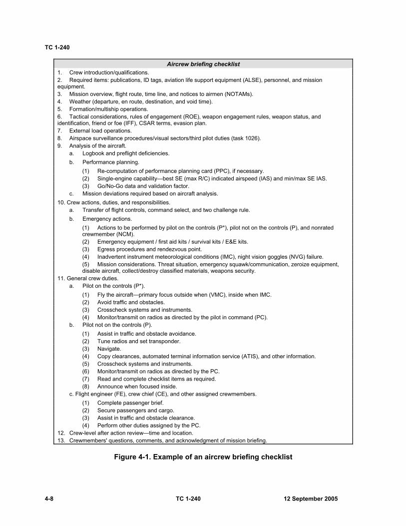
TC 1-240
4-8 TC 1-240 12 September 2005
Aircrew briefing checklist 1. Crew introduction/qualifications. 2. Required items: publications, ID tags, aviation life support equipment (ALSE), personnel, and mission equipment. 3. Mission overview, flight route, time line, and notices to airmen (NOTAMs). 4. Weather (departure, en route, destination, and void time). 5. Formation/multiship operations. 6. Tactical considerations, rules of engagement (ROE), weapon engagement rules, weapon status, and identification, friend or foe (IFF), CSAR terms, evasion plan. 7. External load operations. 8. Airspace surveillance procedures/visual sectors/third pilot duties (task 1026). 9. Analysis of the aircraft.
a. Logbook and preflight deficiencies. b. Performance planning.
(1) Re-computation of performance planning card (PPC), if necessary. (2) Single-engine capability—best SE (max R/C) indicated airspeed (IAS) and min/max SE IAS. (3) Go/No-Go data and validation factor.
c. Mission deviations required based on aircraft analysis. 10. Crew actions, duties, and responsibilities.
a. Transfer of flight controls, command select, and two challenge rule. b. Emergency actions.
(1) Actions to be performed by pilot on the controls (P*), pilot not on the controls (P), and nonrated crewmember (NCM). (2) Emergency equipment / first aid kits / survival kits / E&E kits. (3) Egress procedures and rendezvous point. (4) Inadvertent instrument meteorological conditions (IMC), night vision goggles (NVG) failure. (5) Mission considerations. Threat situation, emergency squawk/communication, zeroize equipment, disable aircraft, collect/destroy classified materials, weapons security.
11. General crew duties. a. Pilot on the controls (P*).
(1) Fly the aircraft—primary focus outside when (VMC), inside when IMC. (2) Avoid traffic and obstacles. (3) Crosscheck systems and instruments. (4) Monitor/transmit on radios as directed by the pilot in command (PC).
b. Pilot not on the controls (P). (1) Assist in traffic and obstacle avoidance. (2) Tune radios and set transponder. (3) Navigate. (4) Copy clearances, automated terminal information service (ATIS), and other information. (5) Crosscheck systems and instruments. (6) Monitor/transmit on radios as directed by the PC. (7) Read and complete checklist items as required. (8) Announce when focused inside.
c. Flight engineer (FE), crew chief (CE), and other assigned crewmembers. (1) Complete passenger brief. (2) Secure passengers and cargo. (3) Assist in traffic and obstacle clearance. (4) Perform other duties assigned by the PC.
12. Crew-level after action review—time and location. 13. Crewmembers' questions, comments, and acknowledgment of mission briefing.
Figure 4-1. Example of an aircrew briefing checklist
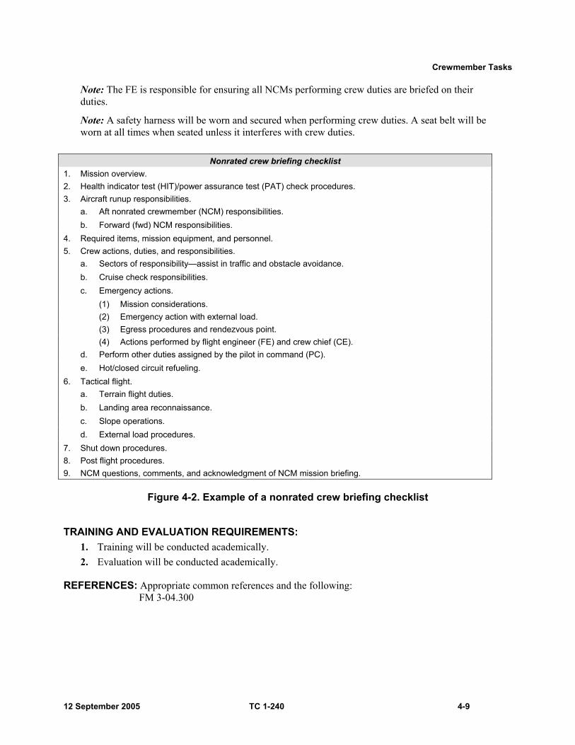
Crewmember Tasks
12 September 2005 TC 1-240 4-9
Note: The FE is responsible for ensuring all NCMs performing crew duties are briefed on their duties.
Note: A safety harness will be worn and secured when performing crew duties. A seat belt will be worn at all times when seated unless it interferes with crew duties.
Nonrated crew briefing checklist
1. Mission overview. 2. Health indicator test (HIT)/power assurance test (PAT) check procedures. 3. Aircraft runup responsibilities.
a. Aft nonrated crewmember (NCM) responsibilities. b. Forward (fwd) NCM responsibilities.
4. Required items, mission equipment, and personnel. 5. Crew actions, duties, and responsibilities.
a. Sectors of responsibility—assist in traffic and obstacle avoidance. b. Cruise check responsibilities. c. Emergency actions.
(1) Mission considerations. (2) Emergency action with external load. (3) Egress procedures and rendezvous point. (4) Actions performed by flight engineer (FE) and crew chief (CE).
d. Perform other duties assigned by the pilot in command (PC). e. Hot/closed circuit refueling.
6. Tactical flight. a. Terrain flight duties. b. Landing area reconnaissance. c. Slope operations. d. External load procedures.
7. Shut down procedures. 8. Post flight procedures. 9. NCM questions, comments, and acknowledgment of NCM mission briefing.
Figure 4-2. Example of a nonrated crew briefing checklist
TRAINING AND EVALUATION REQUIREMENTS: 1. Training will be conducted academically. 2. Evaluation will be conducted academically.
REFERENCES: Appropriate common references and the following: FM 3-04.300

TC 1-240
4-10 TC 1-240 12 September 2005
TASK 1004
Plan a visual flight rules flight
CONDITIONS: Before visual flight rules (VFR) flight in a CH-47 helicopter or CH-47FS, given access to weather information; notices to airmen (NOTAMs); flight planning aids; necessary charts, forms, and publications; weight (WT) and balance information.
STANDARDS: Appropriate common standards and the following additions/modifications: 1. Determine if the aircrew and aircraft are capable of completing the assigned mission. 2. Determine if the flight can be performed under VFR per AR 95-1, applicable FARs/host nation regulations, local regulations, and SOPs. 3. Determine the correct departure, en route, and destination procedures per AR 95-1, applicable FARs/host nation regulations, local regulations, and SOPs. 4. Select routes and altitudes that avoid hazardous weather conditions. Do not exceed aircraft or equipment limitations and conform to VFR cruising altitudes per DOD FLIP. 5. Determine the distance ±1 nautical mile, ground speed ±5 knots, and ETE ±2 minutes for each leg of the flight. Compute magnetic headings ±5 degrees. 6. Determine the fuel required for the mission per AR 95-1, ±100 pounds. 7. Verify that the aircraft will remain within weight and center of gravity (CG) limitations for the duration of the flight per the operator’s manual. 8. Verify aircraft performance data and ensure that power is available to complete the mission per the operator’s manual. 9. Complete and file the flight plan per AR 95-1 and DOD FLIP. 10. Perform mission risk assessment per unit SOP.
DESCRIPTION: 1. Crew actions.
a. The PC may direct other crewmembers to complete some elements of the VFR flight planning. b. The other crewmembers will complete the assigned elements and report the results to the PC.
2. Procedures. Using appropriate military, FAA, or host-country weather facilities, obtain weather information. After ensuring that the flight can be completed under VFR per AR 95-1, check NOTAMs, CHUM, and other appropriate sources for any restrictions that apply to the flight. Obtain navigational charts that cover the entire flight area and allow for routing changes due to the weather or terrain. Select the courses and altitudes that will best facilitate mission accomplishment. Determine the magnetic heading, ground speed, and ETE for each leg. Compute total distance, flight time, and calculate the required fuel using a CPU-26A/P computer/Weems plotter (or equivalent) or mission planning system. Determine if the duplicate weight and balance forms in the aircraft logbook apply to the mission per AR 95-1. Verify that the aircraft weight and CG will remain within allowable limits for the entire flight. Complete the appropriate flight plan and file with appropriate agency.
NIGHT OR NIGHT VISION GOGGLES CONSIDERATIONS: More detailed planning is necessary at night because of visibility restrictions. Checkpoints used during the day may not be suitable for night or NVG use.

Crewmember Tasks
12 September 2005 TC 1-240 4-11
TRAINING AND EVALUATION REQUIREMENTS: 1. Training will be conducted academically. 2. Evaluation will be conducted academically.
REFERENCES: Appropriate common references.

TC 1-240
4-12 TC 1-240 12 September 2005
TASK 1006
Plan an instrument flight rules flight
CONDITIONS: Before Instrument flight rules (IFR) flight in a CH-47 helicopter or a CH-47FS, given access to weather information; notices to airmen (NOTAMs); flight planning aids; necessary charts, forms, and publications; weight (WT) and balance information.
STANDARDS: Appropriate common standards and the following additions/modifications: 1. Determine if the aircrew and aircraft are capable of completing the assigned mission. 2. Determine if the flight can be performed per AR 95-1, applicable FARs/host nation regulations, local regulations, and standing operating procedures (SOPs). 3. Determine the proper departure, en route, and destination procedures per AR 95-1, applicable FARs/host nation regulations, local regulations, and SOPs. 4. Select routes and altitudes that avoid hazardous weather conditions. Do not exceed aircraft or equipment limitations and conform to IFR cruising altitudes per DOD FLIP. If off-airway, determine the courses ±5 degrees and determine the off-airway altitude without error. 5. Select an approach that is compatible with the weather, approach facilities, and aircraft equipment; and determine if an alternate airfield is required per AR 95-1, applicable FARs/host nation regulations, local regulations, and SOPs. 6. Determine distance ±1 nautical mile, true airspeed ±5 knots, ground speed ±5 knots, and ETE ±2 minutes for each leg of the flight. 7. Determine the fuel required for the mission per AR 95-1, ±100 pounds. 8. Verify that the aircraft will remain within weight and center of gravity (CG) limitations for the duration of the flight per the operator’s manual. 9. Verify aircraft performance data and ensure that power is available to complete the mission per the operator’s manual. 10. Complete and file the flight plan per AR 95-1 and the DOD FLIP. 11. Perform mission risk assessment per unit SOP.
DESCRIPTION: 1. Crew actions.
a. The PC will ensure that all crewmembers are current and qualified to perform the mission. He will also determine if the aircraft is equipped to accomplish the assigned mission. The PC may direct the other rated crewmember (RCM) to complete some flight planning elements. b. The other RCM will complete the assigned elements and report the results to the PC. c. Procedures. Using appropriate military, FAA, or host-country weather facilities, obtain weather information. Compare destination forecast and approach minimums, and determine if an alternate airfield is required. Ensure that the flight can be completed per AR 95-1. Check the NOTAMs and other appropriate sources for any restrictions that apply to the flight. Obtain navigation charts that cover the entire flight area and allow for routing or destination changes due to the weather. Select the routes or courses and altitudes that will best facilitate mission accomplishment. When possible, select preferred routing. Determine the magnetic heading, ground speed, and ETE for each leg, to include flight to the alternate airfield if required. Compute the total distance, flight time, and calculate the required fuel using a CPU-26A/P computer/Weems plotter (or equivalent) or mission

Crewmember Tasks
12 September 2005 TC 1-240 4-13
planning system. Determine if the weight and balance forms in the aircraft logbook apply to the mission per AR 95-1. Verify that the aircraft weight and CG will remain within allowable limits for the entire flight. Complete the appropriate flight plan and file it with the appropriate agency.
Note: GPS IFR navigation is not authorized in the CH-47 unless the navigation equipment is approved by the FAA. However, crews should consider and plan for its use as an emergency backup system only. FAA-approved IFR GPS systems possess specific protected terminal instrument procedure data that cannot be altered by the aircrew. The CH-47 GPS system currently does not meet FAA certification requirements.
TRAINING AND EVALUATION REQUIREMENTS: 1. Training will be conducted academically. 2. Evaluation will be conducted academically.
REFERENCES: Appropriate common references.
TC 1-240
4-14 TC 1-240 12 September 2005
TASK 1010
Prepare a performance planning card
CONDITIONS: Given the aircraft takeoff gross weight (GWT); the operator’s manual; environmental conditions at departure, cruise, and arrival; a blank DA Form 5701-47-R (CH-47 Performance Planning Card), or a computer with the AMCOM approved performance planning card (PPC) software.
STANDARDS: Appropriate common standards and the following additions/modifications: Compute performance planning data per TM 1-1520-240-10 and the descriptions below or use the AMCOM-approved performance planning software.
Note: Using the operator’s manual to complete the PPC is required during the APART standardization evaluation.
DESCRIPTION: 1. Crew duties. The PC will compute or direct other rated crewmembers to compute the aircraft performance data required to complete the mission. He will verify the accuracy of the computations, and ensure that aircraft performance meets mission requirements and that aircraft limitations will not be exceeded. All missions will be planned to remain within the continuous power limits. During the pre-mission planning phase, the PPC values should indicate that dual engine continuous power will not be exceeded or the mission profile should be reconfigured. This does not preclude flight within time-limited operations. 2. Procedures.
a. Determine and have available aircraft performance data required to complete the mission. DA Form 5701-47-R (see figure 4-3) may be used to aid with organizing performance-planning data required for the mission. This form will be used for RL progression training, APART evaluations, and when required during other training and evaluations. b. When significant changes in the mission’s environmental conditions occur, recompute all affected values. Arrival data is not required to be completed when manually computing the PPC if environmental data at destination or intermediate stops has not significantly changed. Anytime the environmental conditions change significantly, the crew will perform additional hover power checks and recompute all PPC values. A significant change is defines as ±1,000 feet pressure altitude (PA), and/or ±10 degrees Celsius or an increase of 1,000 pounds GWT from the departure data.
Note: Use mission forecast conditions to obtain the most accurate performance data.
Note: If engine air particle separators (EAPs) are installed, apply the appropriate penalty to torque and fuel flow values.
Note: The operator’s manual (chapters 5, 7, and 9), contains examples for using the performance data charts. When an example is cited in this description, refer to the appropriate example in chapters 5, 7, or 9.
Note: If any computed value exceeds operating limitations, enter NA (not available). Additionally, leave value blank when it does not apply.

Crewmember Tasks
12 September 2005 TC 1-240 4-15
Figure 4-3. Performance planning card
TC 1-240
4-16 TC 1-240 12 September 2005
c. Departure data. Item 1—OPERATING WT. Record the operating weight of the aircraft. Used for reference only. Item 2—T/O FUEL WT. Record the takeoff fuel weight. If extended range fuel system (ERFS) is used, add to aircraft total. Used for reference only. Item 3—LOAD. Record the maximum anticipated weight of the load during the mission profile. Used for reference only. Item 4—PRESSURE ALT. Record the PA forecast for the time of departure. Item 5—FAT. Record the free air temperature (FAT) forecast for the time of departure. Item 6—TAKEOFF GWT NO LOAD. Record the takeoff GWT. Item 7—TAKEOFF GWT WITH LOAD. Record the takeoff GWT. Item 8—FUEL MANAGEMENT. Use this space to record the in-flight fuel consumption check, to include time, rate, quantity, fuel burnout, and reserve. Item 9—MAX TQ AVAIL—10 MIN. Using the maximum torque available 10-minute chart and the forecast conditions at departure, record the maximum 10-minute torque limit available for dual-engine operation. This number represents the maximum 10-minute torque output (or the maximum 10-minute limit for power turbine inlet temperature [PTIT]) that both engines can produce under these forecast conditions. If the dual-engine transmission (XMSN) torque limit line is reached before the planned PA, enter 100 percent. This represents a XMSN limit; the engines may produce power in excess of the XMSN limit. Item 10—MAX TQ AVAIL—(SINGLE-ENGINE). Using the single-engine emergency power (L-712) or contingency torque available (L-714) chart and the forecast conditions at departure, record the maximum torque available for single-engine operation. This number represents the maximum single-engine torque (or the maximum single-engine emergency or contingency power [PTIT] output that one engine can produce. If the single-engine XMSN torque limit line is reached before the planned PA, enter 123 percent. This represents a XMSN limit; the engine may produce power in excess of the XMSN limit. Item 11—MAX TORQUE AVAILABLE—30-MINUTE (L712) or INTERMEDIATE TORQUE AVAILABLE (30-MINUTE) (L714). Using the maximum torque available 30-minute chart and the forecast conditions at departure, record the maximum 30-minute torque available for dual-engine operation. This number represents the maximum 30-minute torque output (or the maximum 30-minute limit for PTIT) that both engines can produce under these conditions. If the dual-engine XMSN torque limit line is reached before the planned PA, enter 100 percent. This represents a XMSN limit; the engines may produce power in excess of the XMSN limit. Item 12—CONTINUOUS TORQUE AVAIL (DUAL-ENGINE). Using the continuous torque available chart, record continuous torque available for dual-engine operation. This number represents the maximum torque output of both engines while still operating at the maximum normal operating range of the PTIT (or the maximum continuous PTIT). If the dual-engine XMSN torque limit line is reached before the planned PA, enter 100 percent. This represents a XMSN limit; the engines may produce power in excess of the XMSN limit.

Crewmember Tasks
12 September 2005 TC 1-240 4-17
Item 13—CONTINUOUS TORQUE AVAIL (SINGLE-ENGINE). Using the continuous torque available chart and the forecast conditions at time of departure, record continuous torque available for single-engine operation. If the single-engine XMSN torque limit line is reached before the planned PA, enter 123 percent. This represents a XMSN limit; the engine may produce power in excess of the XMSN limit. Reference item 11. Note: If the value for the predicted hover torque (dual engine) is greater than continuous torque (dual engine), the TAKEOFF GWT (item 6 and 7) will be adjusted to ensure the predicted hover torque is at or less than the continuous torque. Item 14—MAX GROSS WEIGHT FOR CONTINUOUS POWER – IGE. Using the hover chart and forecasted conditions at departure, enter the chart at the pressure altitude (PA) and read over to the free air temperature (FAT). Move vertically down to the gross weight section. Then enter the bottom of the chart at the dual engine continuous power, read up to the appropriate hover height (10 feet) and then horizontally to the gross weight section. The point where both the PA/FAT line intersects with the continuous torque/hover height line is the takeoff max gross weight for continuous power. Record the maximum allowable GWT for continuous power to hover at the appropriate hover height. Item 15—MAX GROSS WEIGHT FOR CONTINUOUS POWER – OGE. Using the hover chart and forecasted conditions at departure, enter the chart at the pressure altitude (PA) and read over to the free air temperature (FAT). Move vertically down to the gross weight section. Then enter the bottom of the chart at the dual engine continuous power, read up to the appropriate hover height (40 feet or OGE) and then horizontally to the gross weight section. The point where both the PA/FAT line intersects with the continuous torque/hover height line is the takeoff max gross weight for continuous power. Record the maximum allowable GWT for continuous power to hover at the appropriate hover height. Item 16—PREDICTED HVR TQ IGE (DUAL-ENGINE) NO LOAD. Using the hover chart and the forecast conditions at the time of takeoff, record the torque required to hover at the desired wheel height in-ground effect (IGE). The predicted hover torque may be used to confirm pre-calculated aircraft GWT or to provide the basis for determining a possible torque measuring system malfunction. Item 17—PREDICTED HVR TQ OGE (DUAL-ENGINE) NO LOAD. Using the hover chart and forecast conditions at the time of takeoff, record the torque required to hover out-of-ground effect (OGE). Item 18—PREDICTED HVR TQ IGE (DUAL-ENGINE) WITH A LOAD. Using the hover chart and the forecast conditions at the time of takeoff, record the predicted torque required to hover at an IGE height that will place the load approximately 10-feet above ground level (AGL) for external loads or IGE for internal loads. Item 19—PREDICTED HVR TQ OGE (DUAL-ENGINE) WITH A LOAD. Using the hover chart and the forecast conditions at takeoff, record the predicted torque required to hover OGE.

TC 1-240
4-18 TC 1-240 12 September 2005
Item 20—PREDICTED HVR TQ IGE (SINGLE-ENGINE) NO LOAD. Using the hover chart and the forecast conditions at the time of takeoff, record the torque required to hover at the desired wheel height IGE. Compare to single-engine emergency power/contingency power available (item 10) to determine if sufficient power is available to hover single-engine at the appropriate wheel height. Item 21—PREDICTED HVR TQ OGE (SINGLE-ENGINE) NO LOAD. Using the hover chart and the forecast conditions at takeoff, record the torque required to hover at the desired wheel height OGE. Compare to single-engine emergency/contingency power available (item 10) to determine if sufficient power is available to hover single-engine OGE. Item 22—PREDICTED HVR TQ IGE (SINGLE-ENGINE) WITH A LOAD. Using the hover chart and the forecast conditions at the time of takeoff, record the predicted torque required to hover at an IGE height that will place the load approximately 10-feet AGL for external loads or IGE for internal loads. Compare to single-engine emergency power/contingency power available (item 10) to determine if sufficient power is available to hover single-engine at the desired wheel height. If the power required exceeds the maximum single-engine emergency torque available, enter NA. Item 23—PREDICTED HVR TQ OGE (SINGLE-ENGINE) WITH A LOAD. Using the hover chart and the forecast conditions at the time of takeoff, record the predicted torque required to hover OGE. Compare to single-engine emergency power/contingency power available (item 10) to determine if sufficient power is available to hover single-engine OGE. If the power required exceeds the maximum single-engine emergency torque available, enter NA. Item 24—GO/NO-GO TQ NO LOAD. Using the hover chart and the forecast conditions at the time of takeoff, enter the chart at the maximum torque available (10-minute limit) obtained in item 9. Move vertically to the OGE line and horizontally to the desired hover altitude. Then move vertically down to determine the Go/No-Go value. The Go/No-Go torque value, calculated at the desired hover altitude, is proportional to the maximum torque available (10-minute limit) at OGE. That is, if the Go/No-Go torque is exceeded at the desired hover altitude, then maximum torque available (10-minute limit) will be exceeded if OGE maneuvers are attempted. OGE maneuvers should not be attempted if Go/No-Go torque is exceeded. Item 25—GO/NO-GO TQ WITH LOAD Using the hover chart and the forecast conditions at the time of takeoff, record the Go/No-Go torque. Reference item 24. Item 26—MAX ALLOW GWT—IGE (DUAL-ENGINE). Using the hover chart or the hover ceiling chart (maximum GWT to hover) and the forecast conditions at the time of takeoff, record the maximum allowable GWT to hover at the desired wheel height IGE. Item 27—MAX ALLOW GWT—OGE (DUAL-ENGINE). Using the hover chart or the hover ceiling chart (maximum GWT to hover) and the forecast conditions at the time of takeoff, record the maximum allowable GWT to hover OGE. Item 28—MAX ALLOW GWT—IGE (SINGLE-ENGINE). Using the hover chart, the maximum single-engine emergency torque/contingency power available (item 10), and the forecast conditions at the time of takeoff, record the maximum allowable GWT to hover single-engine at the desired wheel height IGE. To calculate, enter the bottom left portion of the hover chart using the maximum
Crewmember Tasks
12 September 2005 TC 1-240 4-19
single-engine emergency torque/contingency power available calculated in item 10. Move up vertically until the 10-foot/IGE line is intersected, and then move right horizontally to the GWT chart (bottom right chart). Now enter the upper chart at the planned PA and move right horizontally to the planned temperature. Then move down vertically to the GWT section from the top. The intersection of the horizontal and vertical lines represents the maximum GWT to hover single-engine IGE. Item 29—MAX ALLOW GWT—OGE (SINGLE-ENGINE). Using the hover chart and maximum single-engine emergency torque available/contingency power available (item 10), record the maximum allowable GWT to hover for single-engine operation OGE for forecast conditions. Use the same procedure as item 27, except continue vertically upward to the 80-foot OGE line, then continue as in item 27 to obtain the maximum GWT to hover single-engine OGE. Note: The procedure for calculating items 26, 27, 28, and 29 apply to both “NO LOAD” and “WITH A LOAD.”
Item 30—VALIDATION FACTOR NO LOAD. Using the hover chart and the forecast conditions at the time of departure, record the predicted torque required to hover at the appropriate hover altitude and at the maximum allowable GWT for the mission profile (item 26 or 27). The maximum allowable GWT for the mission profile is based on either the maximum GWT of the aircraft (structural limit) or the maximum allowable GWT for the operating environment. To calculate, enter the hover chart at the forecast PA at departure time and move right horizontally to the forecast temperature at the time of departure. Move down vertically to the GWT chart until the lowest maximum GWT calculated for the mission profile is intersected. Move left horizontally until the desired hover altitude IGE (or OGE if appropriate) is intersected, then move down vertically to the predicted hover torque (dual-engine). Item 31—VALIDATION FACTOR WITH A LOAD. Using the hover chart and forecast conditions at the time of departure, record the predicted torque required to hover at the appropriate hover altitude and at the maximum allowable GWT for the mission profile. Calculate the same as in item 30. Note: Anticipated weight of expendables (such as fuel) prior to the most limiting point in the mission profile may be factored into mission planning and, thus, performance planning.
d. Cruise data. Item 32—AIRSPEED LIMIT NO LOAD. Using the airspeed operating limits chart with inoperative cruise guide indicator (CGI) (programmed longitudinal cyclic trim), record the maximum indicated airspeed (IAS) for forecast cruise conditions. This chart is located in chapter 5 of the operator’s manual. Item 33—AIRSPEED LIMIT WITH A LOAD. Using the airspeed operating limits chart with inoperative CGI (programmed longitudinal cyclic trim), record the maximum IAS for forecast cruise conditions. Item 34—LCT RET Vne NO LOAD. Using the airspeed operating limits chart (retracted longitudinal cyclic trim), record the maximum IAS for forecast cruise conditions. This chart is located in chapter 5 of the operator’s manual.

TC 1-240
4-20 TC 1-240 12 September 2005
Item 35—LCT RET Vne WITH A LOAD. Using the airspeed operating limits chart (retracted longitudinal cyclic trim), record the maximum IAS for forecast cruise conditions. Item 36—DRAG FACTOR. Using the drag chart, the drag area change of the external load, the forecast cruise conditions, and the cruise airspeed in item 49 and item 51, record the additional torque required for cruise with an external load. Item 37—PRESSURE ALT. Record the planned cruise or highest PA along the route. Item 38—FAT. Record the forecast FAT at cruise or at the highest PA. Item 39—MAX TQ AVAIL—10 MIN. Using the maximum torque available 10-minute chart and the forecast cruise conditions, record the maximum 10-minute torque limit available for dual-engine operation. Reference item 9. Item 40—MAX TQ AVAIL—(SINGLE-ENGINE). Using the single-engine emergency power (L-712) or contingency torque available (L-714) chart and the forecast cruise conditions, record the single-engine emergency torque available. Reference item 10. Item 41—CONTINUOUS TORQUE AVAIL. Using the continuous torque available chart and the forecast cruise conditions, record continuous torque available for dual-engine operation. Reference item 12. Item 42—CONTINUOUS TORQUE AVAIL (SINGLE-ENGINE). Using the continuous torque available chart and the forecast cruise conditions, record continuous torque available for single-engine operation. Reference item 13. Item 43— MAX GROSS WEIGHT FOR CONTINUOUS POWER–CRUISE NO LOAD. Using the applicable cruise chart for the highest cruise altitude and associated temperature for the planned route of flight, enter the chart at the continuous power available torque (see item 41) or torque available (continuous) power line located on the cruise chart. Move up to the desired cruise IAS and intersect the maximum GWT for continuous power. If the aircraft GWT line is to the left of the intersected torque available (continuous) power line located on the chart and the desired cruise IAS, the aircraft will remain within continuous power during the mission profile. If the mission requires higher GWTs, move vertically on the continuous power line until the mission GWT line is intersected. Move laterally to read the cruise IAS to maintain power setting in the continuous power range. Note: By trading off airspeed for GWT, and vice versa, power required for cruise flight will remain at or left of the continuous power line on the cruise charts. Item 44— MAX GROSS WEIGHT FOR CONTINUOUS POWER–CRUISE WITH A LOAD. Using the applicable cruise chart for the highest cruise altitude and associated temperature for the planned route of flight, enter the chart at the continuous power available torque (see item 41) or torque available (continuous) power line, minus drag factor for external loads. Reference item 43. Item 45—MAX R/C and ENDURANCE IAS (DUAL-ENGINE) NO LOAD. Using the applicable cruise chart, record the maximum rate of climb and endurance IAS for the aircraft weight. This airspeed also represents the best single-engine airspeed in a single-engine configuration. Item 46—MAX R/C and ENDURANCE IAS (DUAL-ENGINE) WITH A LOAD. Using the applicable cruise chart, record the maximum rate of climb and endurance IAS for the aircraft weight. This airspeed also represents the best single-engine
Crewmember Tasks
12 September 2005 TC 1-240 4-21
airspeed in a single-engine configuration. Note: The effect of external drag is not accounted for in item 46.
Item 47—MAX RANGE IAS (DUAL-ENGINE) NO LOAD. Using the applicable cruise chart, record the maximum range IAS for the aircraft weight. If the velocity cruise guide indicator (Vcgi) line is intercepted before the maximum range line, enter the Vcgi airspeed limit. Item 48—MAX RANGE IAS (DUAL-ENGINE) WITH A LOAD. Using the applicable cruise chart, record the maximum range IAS for the aircraft weight. If the Vcgi line is intercepted before the maximum range line, enter the Vcgi airspeed limit. Note: The effect of external drag is not accounted for in item 48.
Item 49—CRUISE SPEED—IAS (DUAL-ENGINE) NO LOAD. Select and enter the desired cruise speed. Cruise speed should be selected based on operating within continuous power with consideration of operating GWT and environmental conditions. Reference item 43. Additionally, ensure speed selected is not in excess of AIRSPEED LIMIT speed, reference item 32, nor the Vcgi line indicated on the cruise charts. Item 50—CRUISE SPEED—IAS (DUAL-ENGINE) WITH A LOAD. Select and enter the desired cruise speed. Cruise speed should be selected based on operating within continuous power with consideration of operating gross weight and environmental conditions. Reference item 44. Additionally, ensure speed selected is not in excess of AIRSPEED LIMIT speed, reference item 33, nor the Vcgi line indicated on the cruise charts. Item 51—CRUISE SPEED—IAS (SINGLE-ENGINE) NO LOAD. Select and enter the desired cruise speed that is not greater than the maximum airspeed for single-engine cruise as computed in item 62, or slower than minimum airspeed for single-engine cruise as computed in item 60. The airspeed calculated in item 45 represents the best single-engine airspeed and should be considered when operating single-engine. Item 52—CRUISE SPEED—IAS (SINGLE-ENGINE) WITH A LOAD. Select and enter the desired cruise speed that is not greater than the maximum airspeed for single-engine cruise as calculated in item 64, or slower than minimum airspeed for single-engine cruise as calculated in item 62. The airspeed calculated in item 46 represents the best single-engine airspeed and should be considered when operating single-engine. Item 53—CRUISE TORQUE (DUAL-ENGINE) NO LOAD. Using the applicable cruise chart, record the torque required to maintain the cruise airspeed listed in item 49. Item 54—CRUISE TORQUE (DUAL-ENGINE) WITH A LOAD. Using the applicable cruise chart, calculate the torque required to maintain the cruise airspeed listed in item 50. Then, add the additional torque required to cruise based on drag as calculated in item 36. If the selected cruise airspeed requires the aircraft to be flown in a time-limited engine operation, a lower cruise airspeed must be selected in item 50 and the drag and cruise torque recalculated.
TC 1-240
4-22 TC 1-240 12 September 2005
Item 55—CRUISE TORQUE (SINGLE-ENGINE) NO LOAD. Using the applicable cruise chart, record the torque required to attain the single-engine cruise airspeed listed in item 51. If the chart does not show single-engine torque, double the torque value shown for dual-engines. Item 56—CRUISE TORQUE (SINGLE-ENGINE) WITH A LOAD. Using the applicable cruise chart, record the torque required to attain the single-engine cruise airspeeds listed in item 52. If the chart does not show single-engine torque, double the torque value shown for dual-engines. Note: For items 54 and 56, adjust the cruise torque to compensate for drag caused by changes in the external configuration. Refer to item 36 for drag factor.
Item 57—CRUISE FUEL FLOW (DUAL-ENGINE) NO LOAD. Using the appropriate cruise chart and the torque value listed in item 53, record the predicted fuel flow. Item 58—CRUISE FUEL FLOW (DUAL-ENGINE) WITH A LOAD. Using the appropriate cruise chart and the torque value listed in item 54, record the predicted fuel flow. Item 59—CRUISE FUEL FLOW (SINGLE-ENGINE) NO LOAD. Using the single-engine fuel flow chart and the torque value listed in item 55, record the predicted fuel flow. The baseline is 0 degrees, therefore increase or decrease this fuel flow by 1 percent for every 10 degrees Celsius temperature change from the baseline temperature. Item 60—CRUISE FUEL FLOW (SINGLE-ENGINE) WITH A LOAD. Using the single-engine fuel flow chart and the torque value listed in item 56, record the predicted fuel flow. Increase or decrease this fuel flow by 1 percent for every 10 degrees Celsius temperature change from the baseline temperature. Item 61—MINIMUM SINGLE-ENGINE IAS NO LOAD. Using the appropriate cruise chart, enter the chart at 50 percent of the computed single-engine emergency torque available for cruise conditions. Move vertically to the first intersection of the actual GWT line. If the intersection is below the maximum R/C and endurance airspeed line, record the airspeed that will allow continued single-engine operation. If the torque line is to the left of the actual GWT line and does not intersect the actual GWT line, enter NA for the minimum airspeed. When the torque line is to the right of the actual GWT line and does not intersect the actual GWT line below the maximum R/C and endurance airspeed line, enter OGE for the minimum airspeed that will allow continued single-engine operation. Item 62—MINIMUM SINGLE-ENGINE IAS WITH A LOAD. Using the appropriate cruise chart, enter the chart at 50 percent of the computed single-engine emergency torque available for cruise conditions. Move vertically to the first intersection of the actual GWT line. If the intersection is below the maximum R/C and endurance airspeed line, record the airspeed that will allow continued single-engine operation. If the torque line is to the left of the actual GWT line and does not intersect the actual GWT line, enter NA for the minimum airspeed. When the torque line is to the right of the actual GWT line and does not intersect the actual GWT line below the maximum R/C and endurance airspeed line, enter OGE for the minimum airspeed that will allow continued single-engine operation. Note: The effect of external drag is not accounted for in item 62.

Crewmember Tasks
12 September 2005 TC 1-240 4-23
Item 63—MAXIMUM SINGLE-ENGINE IAS NO LOAD. Using the appropriate cruise chart, enter the chart at 50 percent of the computed single-engine emergency torque available for cruise conditions. Move vertically to the intersection of the actual GWT line above the maximum R/C and endurance airspeed line. Record the maximum airspeed that will allow continued single operation. If the torque line is to the left of the actual GWT line and does not intersect the actual GWT line, enter NA for the maximum airspeed. Item 64—MAXIMUM SINGLE-ENGINE IAS WITH A LOAD. Using the appropriate cruise chart, enter the chart at 50 percent of the computed single-engine emergency torque available for cruise conditions. Move vertically to the intersection of the actual GWT line above the maximum R/C and endurance airspeed line. Record the maximum airspeed that will allow continued single operation. If the torque line is to the left of the actual GWT line and does not intersect the actual GWT line, enter NA for the maximum airspeed. Note: The effect of drag on an external drag is not accounted for in item 64.
Item 65 – MAX GWT SINGLE ENG. Using the single-engine service ceiling chart in the operator’s manual, chapter 9, record the maximum allowable GWT that will allow sustained single-engine flight at the planned cruise PA to be flown for the mission. This value is based on maximum endurance/rate of climb airspeed. Item 66—SESC (SINGLE-ENGINE SERVICE CEILING) NO LOAD. Using the single-engine service ceiling chart in chapter 9 of the operator’s manual, record the maximum altitude attainable that will allow sustained single-engine flight using the actual aircraft GWT and forecast conditions. This value is based on maximum endurance/rate of climb airspeed. Item 67—SESC (SINGLE-ENGINE SERVICE CEILING) WITH A LOAD. Using the single-engine service ceiling chart in chapter 9 of the operator’s manual, record the maximum altitude attainable that will allow sustained single-engine flight using the actual aircraft GWT and forecast conditions. This value is based on maximum endurance/rate of climb airspeed. e. Arrival data. Not required when manually computing the PPC if environmental data at destination or intermediate stops has not significantly changed (±1,000 feet pressure altitude (PA), and/or ±10 degrees Celsius) or an increase of 1,000 pounds GWT from the departure data. Item 68—LANDING GWT. Record the estimated landing GWT. Item 69—LANDING GWT WITH A LOAD. Record the estimated landing GWT. Item 70—PRESSURE ALT. Record the forecast PA at destination at estimated time of arrival (ETA). Item 71—FAT. Record the forecast FAT at destination at ETA. Item 72—MAX TQ AVAIL—10 MIN. Using the maximum torque available 10-minute chart and the forecast arrival conditions, record the maximum torque available for dual-engine operation. Reference item 9. Item 73—MAX TQ AVAIL—(SINGLE-ENGINE). Using the single-engine emergency power (L-712) or contingency torque available (L-714) chart and the forecast arrival conditions, record the maximum torque available for single-engine operation. Reference item 10.

TC 1-240
4-24 TC 1-240 12 September 2005
Item 74—MAX TQ AVAIL—30 MIN (L712) or INTERMEDIATE TORQUE AVAILABLE (L714). Using the maximum torque available 30-minute chart and the forecast arrival conditions, record the maximum torque available (30 minutes) for dual-engine operation. Reference item 11. Item 75—CONTINUOUS TORQUE AVAIL (DUAL-ENGINE). Using the continuous torque available chart, record continuous torque available for dual-engine operation. Reference item 12. Item 76—CONTINUOUS TORQUE AVAIL (SINGLE-ENGINE). Using the continuous torque available chart and the forecast conditions at time of arrival, record continuous torque available for single-engine operation. Reference item 13. Note: If the value for the predicted hover torque (dual engine) is greater than continuous torque (dual engine), the TAKEOFF GWT (item 6/7) will be adjusted (i.e. adjust fuel or cargo prior to takeoff) to ensure the predicted hover torque is at or less than the continuous torque for arrival. Item 77—MAX GROSS WEIGHT FOR CONTINUOUS POWER IGE. Using the hover chart and forecasted conditions at arrival, enter the chart at the pressure altitude (PA) and read over to the free air temperature (FAT). Move vertically down to the gross weight section. Then enter the bottom of the chart at the dual engine continuous power, read up to the appropriate hover height (10 feet) and then horizontally to the gross weight section. The point where both the PA/FAT line intersects with the continuous torque/hover height line is the landing max gross weight for continuous power. Record the maximum GWT for continuous power to hover at the appropriate hover height. Item 78—MAX GROSS WEIGHT FOR CONTINUOUS POWER OGE. Using the hover chart and forecasted conditions at arrival, enter the chart at the pressure altitude (PA) and read over to the free air temperature (FAT). Move vertically down to the gross weight section. Then enter the bottom of the chart at the dual engine continuous power, read up to the appropriate hover height (40 feet or the OGE line) and then horizontally to the gross weight section. The point where both the PA/FAT line intersects with the continuous torque/hover height line is the landing max gross weight for continuous power. Record the maximum GWT for continuous power to hover at the appropriate hover height. Item 79—PREDICTED HVR TQ—IGE (DUAL-ENGINE) NO LOAD. Using the hover chart and the forecast arrival conditions, record the torque required to hover at the desired wheel height IGE for forecast arrival conditions. Reference item 16. Item 80—PREDICTED HVR TQ—OGE (DUAL-ENGINE) NO LOAD. Using the hover chart and the forecast arrival conditions, record the torque required to hover at the desired wheel height OGE. Reference item 17. Item 81—PREDICTED HVR TQ—IGE (DUAL-ENGINE) WITH A LOAD. Using the hover chart and the forecast arrival conditions, record the predicted torque required to hover at a height that will place the load approximately 10 feet AGL and IGE. Reference item 18. Item 82—PREDICTED HVR TQ—OGE (DUAL-ENGINE) WITH A LOAD. Using the hover chart and the forecast arrival conditions, record the predicted torque required to hover OGE. Reference item 19.
Crewmember Tasks
12 September 2005 TC 1-240 4-25
Item 83—PREDICTED HVR TQ—IGE (SINGLE-ENGINE) NO LOAD. Using the hover chart and the forecast arrival conditions, record the torque required to hover at the desired wheel height IGE. Reference item 20. Item 84—PREDICTED HVR TQ—OGE (SINGLE-ENGINE) NO LOAD. Using the hover chart and the forecast arrival conditions, record the torque required to hover at the desired wheel height OGE. Reference item 21. Item 85—PREDICTED HVR TQ—IGE (SINGLE-ENGINE) WITH A LOAD. Using the hover chart and the forecast arrival conditions, record the predicted torque required to hover at a height that will place the load approximately 10 feet AGL and IGE. If the required power exceeds the maximum single-engine emergency torque available, enter NA. Reference item 22. Item 86—PREDICTED HVR TQ—OGE (SINGLE-ENGINE) WITH A LOAD. Using the hover chart and the forecast arrival conditions, record the predicted torque required to hover single-engine OGE. Compare single-engine emergency power/contingency power available (item 73) to determine if sufficient power is available to hover single-engine OGE. If the required power to hover single-engine OGE exceeds the maximum single-engine emergency torque/contingency power available (item 73), enter NA. Item 87—MAX ALLOW. GWT—IGE (DUAL-ENGINE). Using the hover chart and the maximum torque available obtained in item 72 or the hover ceiling chart (maximum GWT to hover) and the forecast arrival conditions, record the maximum allowable GWT to hover at the desired wheel height IGE. Reference item 26. Item 88—MAX ALLOW. GWT—OGE (DUAL-ENGINE). Using the hover chart and the maximum torque available obtained in item 72 or the hover ceiling chart (maximum GWT to hover) and the forecast arrival conditions, record the maximum allowable GWT to hover OGE for forecast arrival conditions. Reference item 27. Item 89—MAX ALLOW. GWT—IGE (SINGLE-ENGINE). Using the hover chart, maximum single-engine emergency torque available obtained in item 73, and the forecast arrival conditions, record the maximum allowable GWT to hover for single-engine operation at the desired wheel height IGE. Reference item 28. Item 90—MAX ALLOW. GWT—OGE (SINGLE-ENGINE). Using the hover chart, maximum single-engine emergency torque available obtained in item 73, and the forecast arrival conditions, record the maximum allowable GWT to hover for single-engine operation OGE. Reference item 29. Note: Items 87, 88, 89, and 90 apply to both “NO LOAD” and “WITH A LOAD.”
TRAINING AND EVALUATION REQUIREMENTS: Training and evaluation will be conducted academically.
REFERENCE: TM 1-1520-240-10.

TC 1-240
4-26 TC 1-240 12 September 2005
TASK 1012
Verify aircraft weight and balance
CONDITIONS: Given crew weights, aircraft configuration, mission cargo, passenger data, the operator’s manual, and completed DD Forms 365-4 (Weight and Balance Clearance Form F-Transport/Tactical).
STANDARDS: Appropriate common standards and the following additions/modifications: 1. Verify that center of gravity (CG) and gross weight (GWT) remain within aircraft limits for the duration of the flight per the operator’s manual. 2. Identify all mission or flight limitations imposed by weight or CG.
DESCRIPTION: 1. Crew actions.
a. Pilot in command (PC) will brief crewmembers on any limitations. b. Crewmembers will continually monitor aircraft loading during the mission (such as fuel transfers, sling loads, and cargo load) to ensure CG remains within limits.
2. Procedures. a. Using the completed DD Forms 365-4 from the aircraft logbook, verify that aircraft GWT and CG will remain within the allowable limits for the entire flight. Note GWT and/or loading restrictions/aircraft limitations. If there is not a completed DD Form 365-4 that meets the requirements of AR 95-1, prepare a DD Form 365-4 per the operator’s manual and TM 55-1500-342-23. b. Verify the aircraft CG in relation to CG limits at predetermined times during the flight when an aircraft’s configuration requires special attention; for example, when it is a critical requirement to keep a certain amount of fuel in a particular tank. Conduct CG checks for fuel, sling, and cargo loading operations.
TRAINING AND EVALUATION REQUIREMENTS: 1. Training will be conducted academically. 2. Evaluation will be conducted orally or academically.
REFERENCES: Appropriate common references and the following: TM 55-1500-342-23

Crewmember Tasks
12 September 2005 TC 1-240 4-27
TASK 1014
Operate aviation life support equipment
CONDITIONS: Given the appropriate aviation life support equipment (ALSE) for the mission.
STANDARDS: Appropriate common standards and the following additions/modifications: 1. Inspect/perform operational checks on ALSE. 2. Use ALSE per the appropriate operator’s manual/instructions for each piece of equipment. 3. Assist passengers in the use of ALSE.
DESCRIPTION: 1. Crew actions. The pilot in command (PC) will verify that all required ALSE equipment is onboard the aircraft and meets all serviceability criteria before takeoff. 2. Procedures. Based on mission requirements, obtain the required ALSE. Inspect equipment for serviceability and perform required operational checks. Secure the required ALSE in the aircraft per AR 95-1, TM 1-1520-240-10, TM 1-1520-240-CL, and the unit’s standing operating procedures (SOP). Brief passengers in the use of ALSE.
TRAINING AND EVALUATION REQUIREMENTS: 1. Training will be conducted academically. 2. Evaluation will be conducted academically.
REFERENCES: Appropriate common references and the following: EM0250 NCM ETP 2C-011-0002-A TM 5-4220-202-14 TM 55-1680-317-23&P TM 55-1680-351-10

TC 1-240
4-28 TC 1-240 12 September 2005
TASK 1016
Perform internal load operations
CONDITIONS: In a CH-47 helicopter loaded with passengers/cargo, or academically.
STANDARDS: Appropriate common standards and the following additions/modifications: 1. Rated crewmember.
a. Ensure that a thorough passenger briefing has been conducted and that a passenger manifest is on file, if applicable. Conduct the briefing per the operator’s manual/checklist (CL) and the unit’s standing operating procedures (SOP). b. Verify that the aircraft will remain within gross weight (GWT) and center of gravity (CG) limitations. c. Ensure that the passengers and cargo are properly restrained. d. Ensure that floor-loading limits are not exceeded. e. Ensure that cargo meets restraint criteria.
2. Nonrated crewmember. a. Perform a thorough passenger briefing and ensure that a passenger manifest is on file, if applicable. Conduct the briefing per the operator’s manual/CL and the unit SOP. b. Load the aircraft per the load plan, if applicable. c. Ensure that floor-loading limits are not exceeded. d. Secure passengers and cargo. e. Ensure that cargo meets restraint criteria.
DESCRIPTION: 1. Crew actions.
a. The pilot in command (PC) (with flight engineer [FE] assistance) will formulate a load plan, ensure that a DD Form 365-4 is verified, if required, and ensure that the aircraft will be within GWT and CG limits. He will ensure that the crew loads the cargo and uses proper tiedown procedures, and any passengers receive a briefing. The PC will determine whether the aircraft is capable of completing the assigned mission and will ensure that aircraft limitations will not be exceeded. b. The pilot not on the controls (P) will perform a hover power check before takeoff and ensure the maximum allowable GWT of the aircraft is not exceeded. c. The nonrated crewmember (NCM) will ensure that passengers are seated and wearing seatbelts before takeoff. He will monitor passengers and cargo during the flight for security.
2. Procedures. a. Load cargo per the cargo plan or DD Form 365-4, as appropriate. Properly secure and restrain all cargo to meet restraint criteria per the appropriate manuals. For additional information, see task 1012. b. Brief passengers for the flight and seat them per the load plan or DD Form 365-4, as appropriate. Conduct the briefing per operator’s manual/CL, unit SOP, and mission information. Ensure that the passengers understand each element of the briefing.

Crewmember Tasks
12 September 2005 TC 1-240 4-29
Note: If the aircraft is not shutdown for loading, a passenger briefing may be impractical. Passengers may be pre-briefed or passenger-briefing cards may be used per local directives or the unit SOP.
Note: Hazardous cargo will be handled, loaded, and transported according to AR 95-27 and the operator’s manual/CL.
TRAINING AND EVALUATION REQUIREMENTS: 1. Training may be conducted in the aircraft or academically. 2. Evaluation may be conducted in the aircraft or academically.
REFERENCES: Appropriate common references and the following: AR 95-27 DA Pam 738-751 FM 10-450-3 FM 55-450-2 TM 38-250 TM 1-1520-240-10 TM 55-1500-342-23
TC 1-240
4-30 TC 1-240 12 September 2005
TASK 1022
Perform preflight inspection
CONDITIONS: With a CH-47 helicopter and given the operator’s manual/CL.
STANDARDS: Appropriate common standards and the following additions/modifications: 1. Rated crewmember (RCM).
a. Perform the preflight inspection per the operator’s manual/checklist (CL). b. Enter appropriate information on the appropriate forms per DA Pamphlet 738-751.
2. Nonrated crewmember (NCM). Assist in all before preflight and preflight duties per the operator’s manual/CL, the unit’s standing operating procedures (SOP), and for the designated duty position.
DESCRIPTION: 1. Crew actions.
a. The pilot in command (PC) is responsible for ensuring that a preflight inspection is conducted using the operator’s manual/CL. The PC may direct other crewmembers to complete elements of the preflight inspection as applicable, and will verify that all checks have been completed per the operator’s manual/CL. He will expediently report aircraft discrepancies that may affect the mission and will ensure that the appropriate information is entered on the appropriate forms per DA Pamphlet 738-751. b. The crewmembers will complete the assigned elements and report the results to the PC.
2. Procedures. a. Ensure that the preflight inspection is conducted per the operator’s manual/CL. Verify that all preflight checks have been completed and ensure that the crewmembers enter the appropriate information on the appropriate forms per DA Pamphlet 738-751. b. As applicable, the PC will ensure that all pertinent data has been loaded into the aircraft (such as COMSEC fills, GPS keys and waypoints, field manuals [FMs], and so forth). c. If circumstances permit, accomplish preflight inspection during daylight hours. d. The NCM will ensure that all cowlings and equipment are secured on completion of preflight.
NIGHT OR NIGHT VISION GOGGLES CONSIDERATIONS: If performing the preflight inspection during the hours of darkness, a flashlight (with an unfiltered lens) should be used to supplement available lighting. Hydraulic leaks, oil leaks, and other defects are difficult to see using a flashlight with a colored lens. Ensure that internal and external lighting is operational. TC 1-204 contains details regarding night time preflight inspection.
TRAINING AND EVALUATION REQUIREMENTS: 1. Training will be conducted at the aircraft. 2. Evaluation will be conducted at the aircraft.
REFERENCES: Appropriate common references and the following: DA Pam 738-751

Crewmember Tasks
12 September 2005 TC 1-240 4-31
TASK 1024
Perform before-starting engine through before-leaving helicopter checks
Note: Any time a nonrated crewmember (NCM) is outside the aircraft, or inside the aircraft with the engines operating and the left-hand escape panel is removed, or the upper cabin door is open, or the ramp cargo door is IN, the NCM’s visor should be down.
CONDITIONS: In a CH-47 helicopter or a CH-47FS and given an operator’s manual/checklist (CL).
STANDARDS: Appropriate common standards and the following additions/modifications: 1. Perform procedures and checks per the operator’s manual/checklist (CL). 2. Comply with call and response terminology as outlined in chapter 6 of this ATM and by unit SOP. 3. Enter appropriate information on DA Form 2408-12 (Army Aviator’s Flight Record), DA Form 2408-13 (Aircraft Status Information Record), and DA Form 2408-13-1 (Aircraft Maintenance and Inspection Record).
DESCRIPTION: 1. Crew actions.
a. Each crewmember will complete the required checks pertaining to his assigned crew duties per the operator’s manual/CL. Crewmembers will coordinate with each other before entering data into aircraft systems. b. The pilot not on the controls (P) will read the checklist and announce auxiliary power unit (APU) and engine starts. c. All crewmembers will clear the area around the aircraft before APU start and each engine start. d. NCMs will perform duties as required by his duty position and as directed by the pilot in command (PC), per the unit’s standing operating procedures (SOP), while maintaining situational awareness. e. Enter appropriate information on DA Forms 2408-12, DA Form 2408-13, and DA Form 2408-13-1 and the HIT/PAT log per the unit SOP and DA Pam 738-751. f. If two or more NCMs will perform flight duties, the flight engineer (FE) will determine which crewmember will perform specific portions of each task. g. Secure the aircraft after completion of the flight per the operator’s manual, TM 1-1520-240-23 series, TM 1-1500-250-23, and the unit SOP.
2. Procedures. a. Perform the before-starting engine through before-leaving helicopter checks per the operator’s manual/CL. The call and response method will be used, as appropriate. b. The crewmember reading the checklist will read the complete checklist item. c. The crewmember performing the check will answer with the appropriate response. For example, for the call “swivel switch—as required,” the response might be “swivel switch, steer.” “As required” is not an appropriate response. Responses that do not clearly communicate action or information should not be used. d. After flight, correctly enter all information required on the appropriate DA Forms. e. During APU start, the NCM will be outside of the aircraft to ensure that the area is clear and to perform fireguard duties.
TC 1-240
4-32 TC 1-240 12 September 2005
f. During engine start, the NCM will assume a position 45 degrees from the front of the engine at the rotor blade tip to ensure that the aircraft is clear and ready for the engine start. g. The NCM/pilots will complete the post flight per the operator’s manual/CL. h. On completion of required maintenance and inspection, the NCM will moor the aircraft and install required protective covers and security devices.
NIGHT OR NIGHT VISION GOGGLES CONSIDERATIONS: Before starting the engines, ensure that all internal and external lights are operational and set. Internal lighting levels must be high enough to easily see the instruments and to start the engines without exceeding operating limitations.
SNOW/SAND/DUST CONSIDERATIONS: Ensure that all rotating components and inlets/exhausts are clear of ice/snow before starting APU/engines.
TRAINING AND EVALUATION REQUIREMENTS: 1. Training may be conducted in the aircraft or the simulator. 2. Evaluations will be conducted in the aircraft.
REFERENCES: Appropriate common references and the following: DA Pam 738-751 ETP 2C-011-0002-A
Crewmember Tasks
12 September 2005 TC 1-240 4-33
TASK 1026
Maintain airspace surveillance
WARNING
While moving about the cabin area during flight, the nonrated crewmembers (NCMs) must be secured to a 5,000-pound tiedown fitting in the cabin area. NCMs will not secure their restraining harness to the ramp.
CONDITIONS: In a CH-47 helicopter or a CH-47FS in visual meteorological conditions (VMC).
STANDARDS: Appropriate common standards and the following additions/modifications: 1. Announce drift or altitude changes, clear the aircraft, and immediately inform other crewmembers of all air traffic or obstacles that pose a threat to the aircraft. 2. Announce when attention will be focused inside the aircraft. 3. Maintain airspace surveillance in assigned scan sectors. 4. When landing, the crew will confirm the suitability of the area and that the aircraft is clear of obstacles.
DESCRIPTION: 1. Crew actions.
a. The pilot in command (PC) will brief airspace surveillance procedures before the flight. The briefing will include areas of responsibility and scan sectors. b. The pilot on the controls (P*) will announce his intent to perform a specific maneuver and will remain focused outside the aircraft. He is responsible for clearing the aircraft and avoiding obstacles. c. Crewmembers will assist in clearing the aircraft and will provide adequate warning of obstacles, unusual drift, or altitude changes. They will announce when their attention is focused inside the aircraft and again when attention is reestablished outside. d. When landing, the crew will confirm the suitability of the area and that the aircraft is clear of obstacles. The NCMs will move about the aircraft as necessary to ensure total coverage.
2. Procedures. a. Maintain close surveillance of the surrounding airspace.
(1) Keep the aircraft clear from other aircraft and obstacles by maintaining visual surveillance (close, mid, and far areas) of the surrounding airspace. (2) Inform the crew immediately of air traffic or obstacles that pose a threat to the aircraft. Call out the location of traffic or obstacles by the clock, altitude, and distance method. (The 12 o'clock position is at the nose of the aircraft.) (3) For air traffic, give distance in miles or fractions of miles, as appropriate. When reporting air traffic, specify the type of aircraft, if known. The altitude of the air traffic should be reported as the same altitude, higher, or lower than the altitude at which you are flying.

TC 1-240
4-34 TC 1-240 12 September 2005
(4) For ground obstacles, give distance in miles or feet, as appropriate. b. Before changing altitude, visually and verbally clear the aircraft for hazards and obstacles, including what is ahead, above, to the left, and to the right of the aircraft. c. Before performing a descending flight maneuver, it may sometimes be desirable to perform a clearing “S” turn to the left or right. The clearing “S” turns will provide the aircrew with a greater visual scan area. d. During a hover or hovering flight, inform the P* of unannounced drift or altitude changes. When landing, the crew will confirm the suitability of the area.
NIGHT OR NIGHT VISION GOGGLES CONSIDERATIONS: The use of proper scanning techniques will assist in detecting traffic and obstacles, and in avoiding spatial disorientation. Hazards such as wires are difficult to detect.
TRAINING AND EVALUATION REQUIREMENTS: 1. Training may be conducted in the aircraft or simulator. 2. Evaluation will be conducted in the aircraft.
REFERENCES: Appropriate common references.
Crewmember Tasks
12 September 2005 TC 1-240 4-35
TASK 1027
Perform health indicator test/power assurance test check
CONDITIONS: In a CH-47 helicopter or CH-47FS.
STANDARDS: Appropriate common standards and the following additions/modifications: Complete the health indicator test (HIT) check per the engine health indicator program log or the power assurance test (PAT) check per the PAT log and TM 1-1520-240-10.
DESCRIPTION: 1. Crew actions.
a. The pilot not on the controls (P) will perform the checks in sequence. He should coordinate with, and direct assistance from the pilot on the controls (P*) and nonrated crewmember (NCM), as necessary. b. The P will ensure the P* is familiar with HIT/PAT check procedures. c. Ground procedures.
(1) The P briefs and coordinates with the P* and NCM, as necessary. (2) Position the aircraft into the prevailing wind. Set the brakes and direct assistance, as necessary. (3) Confirm the flight controls are neutral and the thrust control is in the ground detent. Direct the P* to monitor the flight controls and maintain aircraft control when the thrust control is not in the ground detent. (4) Direct the NCM to assist with maintaining obstacle avoidance and advise the cockpit concerning the movement of other aircraft operating in the immediate area.
d. Perform the HIT or PAT per the applicable reference. e. Once the check has been completed for both engines, return to the checklist.
2. Hover procedures. a. The P briefs and coordinates with the P* and NCM, as necessary.
(1) Direct the P* to maintain hover position and heading while maintaining orientation outside the cockpit. (2) Direct the NCM to assist with maintaining obstacle avoidance and advise the cockpit concerning other aircraft/hazards in the area.
b. Perform the PAT per the applicable references. Manipulation of the engine condition levers (ECLs) may not be required if the torques are in the appropriate ranges for the PAT. c. Once the check has been completed for both engines, continue with the checklist.
3. In-flight procedures. a. The in-flight PAT procedure will be conducted only if environmental conditions prevent the check on the ground or hover.
(1) The P briefs and coordinates with the P* and NCM, as necessary. (2) Direct the P* to maintain assigned altitude, heading, and airspeed while maintaining orientation outside the cockpit. (3) Direct the NCM to assist with maintaining obstacle avoidance and advise the cockpit concerning other aircraft/hazards in the area.
TC 1-240
4-36 TC 1-240 12 September 2005
b. Establish the aircraft at the appropriate airspeed while maintaining 100 percent rotor revolutions per minute (RRPM). c. Perform the PAT per the applicable reference. Once the check has been completed for both engines, confirm a systems check and continue with the mission. Manipulation of the ECLs may not be required if the torques are in the appropriate ranges for the PAT.
TRAINING AND EVALUATION REQUIREMENTS: 1. Training may be conducted in the aircraft, flight simulator, or academically. 2. Evaluation will be conducted in the aircraft.
REFERENCES: Appropriate common references.
Crewmember Tasks
12 September 2005 TC 1-240 4-37
TASK 1028
Perform hover power check
CONDITIONS: In a CH-47 helicopter or a CH-47FS, with the before hover check complete, at an appropriate hover height, and with performance planning information available.
STANDARDS: Appropriate common standards and the following additions/modifications: 1. Position the aircraft in the vicinity of the takeoff point and in the direction of takeoff at the appropriate hover height. 2. Determine if sufficient power is available to complete the mission by comparing actual torque to predicted torque, Go/No-Go torque, and the validation factor obtained during performance planning. 3. Determine if single-engine hover capability exists. 4. Determine if aircraft performance is sufficient to complete the mission. 5. Determine if sufficient fuel exist to complete the mission.
DESCRIPTION: 1. Crew actions.
a. The pilot in command (PC) will determine whether the aircraft is capable of completing the assigned mission and will ensure that aircraft limitations will not be exceeded. b. The pilot on the controls (P*) will announce his intent to bring the aircraft to a stationary hover for a hover power check.
(1) During the ascent, check for proper control response. (2) Remain focused outside the aircraft and announce when the aircraft is stabilized at the desired hover altitude. (3) Use a 10-foot stationary hover near the takeoff point and in direction of takeoff when performing a hover power check, unless mission or terrain constraints dictate otherwise. (4) If different hover height is required, use that height during performance planning to compute Go/No-Go torque, validation factor torque, and predicted hover torque.
c. During the ascent, the pilot not on the controls (P) will monitor the torque. (1) If validation factor is approached before reaching desired hover height, the P will announce this in enough time so the P* can take appropriate action. (2) The P will monitor the aircraft instruments, note engine gas producers (speed) (N1s), power turbine inlet temperatures (PTITs), engine oil temperatures, engine oil pressures, and determine if sufficient fuel is available to complete the mission and verify the power check. (3) The P will compare the actual hover performance data to the computed data on the performance planning card (PPC) and announce the results to the P*. If Go/No-Go torque for the desired hover height is indicated before reaching the planned hover height used during performance planning, the P will inform the P* that out-of-ground effect (OGE) maneuvers cannot be conducted. The PC will confirm the Go/No-Go torque and adjust the mission, as required.
d. The nonrated crewmember (NCM) will remain focused primarily outside the aircraft to assist in clearing and to provide adequate warning of obstacles.
TC 1-240
4-38 TC 1-240 12 September 2005
2. Procedures. a. Use the hover height computed during performance planning when performing this task, unless the mission or terrain constraints dictate otherwise. If another hover height is required, use that height to compute Go/No-Go and validation factor torque. See task 1038. b. At desired hover height, monitor the aircraft instruments and verify the power check. The P will determine if single-engine capability exists and will compare actual torque to predicted torque, Go/No-Go torque, and the validation factor. He will ensure that aircraft limitations are not exceeded. c. The PC will ensure that aircraft performance and fuel are sufficient to complete the mission.
Note: If the torque required to maintain a stationary hover does not exceed the Go/No-Go torque OGE, any maneuver requiring OGE/in-ground effect (IGE) power or less may be attempted.
Note: If the torque required to maintain a stationary hover exceeds the Go/No-Go torque OGE, but does not exceed the validation factor IGE, all IGE maneuvers may be attempted.
Note: If the torque required to maintain a stationary hover exceeds the computed validation factor, the maximum gross weight (GWT) may have been exceeded for the environmental conditions present. Any time the GWT or environmental conditions change significantly, the crew will perform additional hover power checks and recompute all PPC values. Significantly changed is defined as ±1,000 feet pressure altitude (PA), and/or ±10 degrees Celsius) or an increase of 1,000 pounds GWT from the departure data.
TRAINING AND EVALUATION REQUIREMENTS: 1. Training will be conducted in the aircraft or flight simulator. 2. Evaluation will be conducted in the aircraft or flight simulator.
REFERENCES: Appropriate common references.

Crewmember Tasks
12 September 2005 TC 1-240 4-39
TASK 1032
Perform radio communication procedures
CONDITIONS: In a CH-47 helicopter or a CH-47FS.
STANDARDS: Appropriate common standards and the following additions/modifications: 1. Rated crewmembers (RCMs).
a. Check and operate aircraft avionics. b. Establish radio contact with the desired unit or air traffic control (ATC) facility. When communicating with ATC facilities, use correct radio communication procedures and phraseology per the AIM, DOD FLIP, and DOT/FAA Order 7110.65. c. Operate intercom system. d. Perform or describe two-way radio failure procedures per the DOD FLIP or host country regulations.
2. Nonrated crewmembers (NCMs). Use the internal communication system to communicate with the crew.
DESCRIPTION: 1. Crew actions.
a. The pilot in command (PC) will determine radio frequencies per mission requirements during the crew briefing and will indicate whether the pilot on the controls (P*) or the pilot not on the controls (P) will establish and maintain primary communications. b. The P* will announce information not monitored by the P. c. The P will adjust avionics to required frequencies. He will copy pertinent information and announce information not monitored by the P*. d. During normal operations, the NCM will monitor external communications to prevent interruption when external communications are transmitted or received. (Monitoring external communications may not be desirable during operations requiring extensive internal communication, such as external loads, hoist, or emergencies.) e. Crew actions for two-way radio failure—
(1) P* or P will announce two-way radio failure to all crewmembers. (2) The PC will direct the efforts to identify and correct the avionics malfunction. (3) The P* will focus outside the aircraft during visual meteorological conditions (VMC) or inside on the instruments during instrument meteorological conditions (IMC), as appropriate, but should not participate in troubleshooting the malfunction. (4) The P will remain focused primarily inside the aircraft to identify and correct the avionics malfunction

TC 1-240
4-40 TC 1-240 12 September 2005
f. Crew actions for aircraft intercom failure— (1) The PC will direct assistance from the crew to determine the malfunction and corrective action. Alternate actions may include switching to a different internal communications system (ICS) box, changing microphone cords if available, hooking up to a different ICS station, hand and arm signals, or passing notes. (2) If the problem cannot be corrected, the PC will determine the course of action, which may vary from landing as soon as practical to landing as soon as possible.
2. Procedures. a. Adjust avionics to the required frequencies. Continuously monitor the avionics as directed by the PC.
(1) When required, establish communications with the desired facility. (2) Monitor the frequency before transmitting. Transmit the desired/required information. Use the correct radio call sign when acknowledging each communication. (3) When advised to change frequencies, acknowledge instructions. Select the new frequency as soon as possible unless instructed to do so at a specific time, fix, or altitude. (4) Use radio communication procedures and phraseology as appropriate for the area of operations. Use standard terms and phraseology for all intercommunications.
b. Procedures for two-way radio failure. Attempt to identify and correct the malfunctioning radio and announce the results. If two-way radio failure is confirmed, comply with procedure outlined in the flight information handbook or host country regulations.
TRAINING AND EVALUATION REQUIREMENTS: 1. Training may be conducted in the aircraft or simulator. 2. Evaluation may be conducted in the aircraft or simulator.
REFERENCES: Appropriate common references and the following: AIM DOD FLIP DOT/FAA Order 7110.65 P/CG

Crewmember Tasks
12 September 2005 TC 1-240 4-41
TASK 1034
Perform ground taxi
CAUTION While turning during a two-wheel taxi, the pilot on the controls (P*) must avoid the forward gear contacting the ground.
CONDITIONS: In a CH-47 helicopter or a CH-47FS on a suitable surface, with the before-taxi/after-landing check completed, and the aircraft cleared.
STANDARDS: Appropriate common standards and the following additions/modifications: 1. Rated crewmember (RCM).
a. Maintain a constant speed appropriate for conditions. b. Maintain the desired ground track. c. Maintain flight controls per the operator’s manual.
2. Nonrated crewmember (NCM). a. Perform applicable checks according to TM 1-1520-240-CL and the unit’s standing operating procedures (SOP) when read by the pilot not on the controls (P). b. Immediately inform the RCMs of any observed discrepancies or malfunctions. c. Clear the aircraft. d. Use hand and arm signals, if required, per FM 21-60.
DESCRIPTION: 1. Two-wheel taxi crew actions.
a. The pilot on the controls (P*) will announce his intent to begin the two-wheel taxi operations, the taxi plan, and the intended direction of any turns. He will remain focused primarily outside the aircraft. The P and NCM will assist the P* in clearing the aircraft. b. The P* will call for the before-taxi check or the taxi check, as appropriate. c. The P will read the appropriate taxi check. He will ensure the aft wheel swivel switch is locked and the advanced flight control system (AFCS) select switch is at BOTH or OFF. He will have the NCM in the ramp area visually confirm that swivel lock actuators are locked. d. The P* will advise the P to monitor ground control limitations and longitudinal cyclic trim (LCT) operation. Initially, the P* will position the cyclic, as necessary, not to exceed 2 inches aft. The P* will release the brakes, as required, and raise the thrust lever until the forward landing gear are clear of the ground. The P* will maintain directional control with the pedals and speed with the thrust control.
(1) During forward taxi, the P* will raise the thrust lever to slow or stop the aircraft. He will lower it to increase forward speed. If desired, the P* will lower the forward gear to the ground while taxiing in a straight line or when all movement is stopped. (2) For back taxi, the P* will raise the thrust lever until the aircraft begins to move rearward. He will maintain directional control with the pedals and speed with the thrust lever. The P* will

TC 1-240
4-42 TC 1-240 12 September 2005
lower the thrust lever to slow or stop the aircraft. He will raise the thrust lever to increase rearward speed. (3) Before two-wheel taxi, the pilot in command (PC) will have the flight engineer (FE)/crew chief (CE) visually confirm that both aft gear are in the trail position and that both aft wheel swivel lock actuators are locked. (4) The P* may use lateral cyclic inputs to assist with directional control. These inputs are normally required when taxiing in a crosswind.
2. Four-wheel taxi crew actions. a. The P* will announce his intent to begin the four-wheel taxi and state his taxi plan. He will call for the before-taxi check or the taxi check, as appropriate. b. The P will read the appropriate taxi check. He will ensure that the swivel switch is at STEER and that the AFCS select switch is OFF. c. The P will advise the P* that he has control of the brakes and the power steering. The P* will monitor LCT operation and take care to not exceed ground control limitations. d. All crewmembers will clear the aircraft as necessary. The P* will raise the thrust lever to start forward movement and then lower it to ground detent. All thrust movements will be announced.
(1) The P will maintain the taxi speed with moderate brake applications, and call for thrust application/reduction as appropriate. (2) The P will slowly rotate the power steering control knob to turn the aircraft in the desired direction. During taxi at light gross weight (GWT), the P may have to advise the P* to apply aft cyclic to prevent a loss of steering control.
e. When the NCM is required outside the aircraft during taxiing, he will position himself where the P*/P can clearly see his hand and arm signals or will remain attached to the aircraft communication system. f. Prior to four-wheel taxi, visually confirm that both aft gear are in the trail position. g. During four-wheel taxi, the P must not allow the power steering control knob to spring back to the neutral position. h. If the LCT actuators cycle between RET and GND because of light loading on the aft landing gear, it may be necessary to apply up to 2 inches of aft cyclic. If this action does not prevent further LCT cycling, set the cyclic trim switch to MANUAL. If the LCTs are not at GND, manually set them to that position. When taxiing is complete and before performing a takeoff to a hover, set the cyclic trim switch to AUTO.
NIGHT OR NIGHT VISION GOGGLES CONSIDERATIONS: The landing light should be used for unaided ground taxi and the searchlight with installed infrared (IR) band pass light filter when wearing night vision goggles (NVG). The use of proper scanning techniques will assist in detecting obstacles that must be avoided.
SNOW/SAND/DUST CONSIDERATIONS: If ground reference is lost because of blowing snow/sand/dust, lower the thrust lever, neutralize the flight controls, and apply wheel brakes until visual reference is reestablished.
Note: Use caution when taxiing near other maneuvering aircraft because of limited visual references and relative motion illusion.
Note: Due to decreased visual references and a possibility of relative motion illusions, limit ground speed to a rate appropriate for the conditions.

Crewmember Tasks
12 September 2005 TC 1-240 4-43
Note: At night, use of the landing, search, or anticollision lights may cause spatial disorientation in blowing snow/sand/dust.
TRAINING AND EVALUATION REQUIREMENTS: 1. Training may be conducted in the aircraft or simulator. 2. Evaluation will be conducted in the aircraft.
REFERENCES: Appropriate common references.
TC 1-240
4-44 TC 1-240 12 September 2005
TASK 1038
Perform hovering flight
CONDITIONS: In a CH-47 helicopter or a CH-47FS with the before hover check completed and the aircraft cleared.
STANDARDS: Appropriate common standards and the following additions/modifications: 1. Perform a smooth, controlled ascent to hover. 2. Perform a smooth, controlled descent with minimal drift at touchdown. 3. Maintain ground track, ±5 feet during hover taxi. 4. Maintain a constant rate of turn, not to exceed 90 degrees within 4 seconds.
DESCRIPTION: 1. Crew actions.
a. The pilot on the controls (P*) will announce his intent to perform a specific hovering flight maneuver and will remain focused primarily outside the aircraft to monitor altitude and avoid obstacles. He will ensure and announce that the aircraft is cleared before turning or repositioning the aircraft. He will announce when he terminates the maneuver. b. The pilot not on the controls (P) and nonrated crewmember (NCM) will assist in clearing the aircraft and provide adequate warning of obstacles and unannounced drift or altitude changes. They will announce when their attention is focused inside the aircraft and again when their attention is reestablished outside.
2. Procedures. a. Takeoff to a hover.
(1) Position the cyclic as necessary, not to exceed 2 inches aft while all four landing gear are on the ground, and maintain heading with the pedals. (2) Smoothly raise the thrust lever and adjust the cyclic to ascend vertically to a 10-foot aft gear height, unless mission requirements dictate another altitude. (3) Release the brakes as necessary.
b. Hovering flight. (1) Adjust the cyclic to maintain a stationary hover or to hover in the desired direction. (2) Control heading with the pedals and maintain altitude with the thrust lever. Maintain a constant hover speed appropriate for the conditions. (3) To return to a stationary hover, apply cyclic in the opposite direction while maintaining heading with the pedals and altitude with the thrust lever.
c. Hovering turns. (1) Around the nose. With the aircraft stationary, pick a point slightly forward of the nose. Control the direction and rate of turn with the cyclic, pedals, and maintain altitude with the thrust lever. (Cross-control of the cyclic and pedals is required to pivot around the nose.) (2) Around the center cargo hook. With the aircraft at a stationary hover and the cargo hook over the pivot point, apply pedal in the desired direction of turn. Maintain a stationary position over the pivot point with the cyclic. Control the rate of turn with the pedals and maintain altitude with the thrust lever.

Crewmember Tasks
12 September 2005 TC 1-240 4-45
(3) Around the tail. With the aircraft at a stationary hover and the pivot point under the tail, apply cyclic and pedal in the direction of the intended turn. Use cyclic and pedal to control the rate of turn and movement. Maintain hover altitude with the thrust lever.
d. Landing from a hover. (1) Lower the thrust lever to affect a smooth rate of descent until the aft gear contacts the ground. (2) Coordinate thrust lever reduction with aft cyclic, as necessary, to maintain pitch attitude and to stop forward movement. (3) Smoothly lower the thrust lever to allow the forward gear to contact the ground. Continue to lower the thrust lever to ground detent, neutralize the controls, and apply brakes to stop forward movement. (4) If sloping conditions are suspected or anticipated, see task 1062.
3. The P and NCM should assist the P* in maintaining the position of the aircraft over the pivot point. 4. When landing from a hover to an unimproved area, the crew must check for obstacles under the aircraft.
NIGHT OR NIGHT VISION GOGGLES CONSIDERATIONS: 1. Movement over areas of limited contrast, such as tall grass, water, or desert tends to cause spatial disorientation. Seek hover areas that provide adequate contrast and use proper scanning techniques. If disorientation occurs, apply sufficient power and execute an instrument takeoff (ITO), task 1170. If a takeoff is not feasible, try to maneuver the aircraft forward and down to the ground to limit the possibility of touchdown with sideward or rearward movement. 2. When performing operations during unaided night flight, ensure the searchlight or landing light (white light) is in the desired position. Use of the white light will impair night vision for several minutes. Therefore, exercise added caution if resuming flight before reaching full dark adaptation.
SNOW/SAND/DUST CONSIDERATIONS: During ascent to a hover, if visual references do not deteriorate to an unacceptable level, continue ascent to the desired hover altitude.
1. Ten-foot hover taxi. During takeoff to a hover, simultaneously accelerate the aircraft to a ground speed that keeps the snow/sand/dust cloud just aft of the cabin door. Note: Maintain optimum visibility by observing references close to the aircraft. Exercise caution when operating in close proximity to other aircraft or obstacles.
Note: When visual references deteriorate making a 10-foot hover taxi unsafe, determine whether to abort the maneuver, ground taxi, air taxi, or perform an ITO task 1170.
2. Twenty-foot to 100-foot air taxi. Use this maneuver when it is necessary to move the aircraft over terrain that is unsuitable for hover taxi. Initiate air taxi the same as a 10-foot hover, but increase altitude normally not more than 100 feet and accelerate to a safe airspeed appropriate for conditions. Note: Ensure an area is available to safely decelerate and land the aircraft. Under certain conditions, such as adverse winds, it may be necessary to perform a traffic pattern to optimize conditions at the desired termination point.
Note: Hovering out-of-ground effect (OGE) reduces available ground references and may increase the possibility of spatial disorientation. Be prepared to transition to instruments and execute an ITO (task 1170) or unusual attitude recovery (task 1182), if ground reference is lost.
TC 1-240
4-46 TC 1-240 12 September 2005
Note: At night, use of landing, search, or anticollision lights may cause spatial disorientation while in blowing snow/sand/dust.
CONFINED AREA CONSIDERATIONS: Select good references to avoid unanticipated drift. All crewmembers must be focused primarily outside for obstacle avoidance.
TRAINING AND EVALUATION REQUIREMENTS: 1. Training may be conducted in the aircraft or simulator. 2. Evaluation will be conducted in the aircraft.
REFERENCES: Appropriate common references.

Crewmember Tasks
12 September 2005 TC 1-240 4-47
TASK 1040
Perform visual meteorological conditions takeoff
CONDITIONS: In a CH-47 helicopter or a CH-47FS with the hover power and before-takeoff checks completed and the aircraft cleared.
STANDARDS: Appropriate common standards and the following additions/modifications: 1. Properly clear the aircraft. 2. Maintain takeoff heading ±10 degrees below 50 feet above ground level (AGL). 3. Maintain ground track aligned with takeoff direction. 4. Maintain aircraft in trim above 50 feet AGL or as appropriate for transition to terrain flight. 5. Maintain takeoff power until reaching minimum single-engine airspeed, desired climb airspeed, or transition to mission profile.
DESCRIPTION: 1. Crew actions.
a. The pilot in command (PC) will determine the direction of takeoff by analyzing the tactical situation, wind, long axis of the takeoff area, and the lowest obstacles. He will ensure required power is available by comparing the information from the performance planning card (PPC) to the hover power check. He will ensure that the required fuel for the mission is available by comparing the required fuel onboard the aircraft to the PPC. If the fuel onboard is inadequate, add sufficient fuel, abort, or revise the mission. b. The pilot on the controls (P*) will remain focused primarily outside the aircraft throughout the maneuver to provide obstacle clearance. He will announce whether the takeoff is from the ground or from a hover and his intent to abort or alter the takeoff. He will select reference points to assist in maintaining the takeoff flight path. c. The pilot not on the controls (P) and nonrated crewmember (NCM) will announce when ready for takeoff and will remain focused primarily outside the aircraft to assist in clearing and to provide adequate warning of obstacles. d. The P will monitor power requirements and advise the P* if power limits are being approached. The P and NCM will announce when their attention is focused inside the aircraft and again when attention is reestablished outside.
2. Procedures. a. From the ground.
(1) The P* will announce his intent to take off from the ground. He will focus his attention primarily outside the aircraft but will occasionally crosscheck the flight instruments. (2) All crewmembers will clear the aircraft. (3) The P* will select reference points to maintain ground track. With the cyclic and pedals in the neutral position, the P* will release the brakes and raise the thrust lever until the aircraft is airborne and accelerating. (4) All landing gear should leave the ground at the same time. As the aircraft leaves the ground, the P* will apply forward cyclic as required to smoothly accelerate through effective translational lift (ETL) at an altitude appropriate for the terrain and obstacles.

TC 1-240
4-48 TC 1-240 12 September 2005
(5) He will adjust the cyclic as necessary to continue the acceleration (approximately 5 degrees nose down), obtain the desired climb airspeed, and maintain ground track. The P* will position the thrust lever as necessary to clear obstacles in the flight path and obtain the desired rate of climb. He will use the pedals to maintain heading when below 50 feet AGL and in trim when above 50 feet AGL. (6) When the P* obtains the desired climb airspeed, he will adjust the cyclic as necessary to stop the acceleration. He will adjust the thrust lever to continue or to stop the rate of climb. The P will confirm longitudinal cyclic trim (LCT) operation.
b. From a hover. (1) The P* will announce his intent to take off from a hover. He will focus his attention primarily outside the aircraft. (2) All crewmembers will clear the aircraft. (3) The P* will select reference points to maintain ground track. He will apply forward cyclic to smoothly accelerate the aircraft through ETL while adjusting the thrust lever, as required, to maintain the appropriate hover height. The P* will perform the rest of the maneuver as for a takeoff from the ground.
Note: Performing this maneuver in certain environments may require hover OGE power. Evaluate each situation for power required versus power available, such as terrain flight takeoff.
Note: The P* must avoid excessive and unnecessary nose-low accelerative attitudes.
Note: The NCMs should remain seated during this maneuver.
NIGHT OR NIGHT VISION GOGGLES CONSIDERATIONS: 1. If sufficient illumination exists to view obstacles, accomplish the takeoff in the same way as a visual meteorological condition (VMC) takeoff during the day. Visual obstacles, such as shadows, should be treated the same as physical obstacles. 2. If sufficient illumination does not exist, perform an altitude-over-airspeed takeoff by applying takeoff power first, followed by a slow acceleration to ensure obstacle clearance. The P* may perform the takeoff from a hover or from the ground.
a. Maintain the takeoff power setting until reaching climb airspeed. Adjust power as required to establish the desired rate of climb and cyclic to maintain the desired airspeed. Cross-check instruments while assisting with obstacle avoidance. The P* and NCM should maintain orientation outside the aircraft and concentrate on obstacle avoidance. The P should make all internal checks. b. Reduced visual references during the takeoff and throughout the ascent at night may make it difficult to maintain the desired ground track. Knowledge of the surface wind direction and velocity will assist in maintaining the desired ground track. c. Use proper scanning techniques to avoid spatial disorientation. d. When performing operations during unaided night flight, ensure that the searchlight or landing light (white light) is in the desired position. Use of the white light may impair night vision for several minutes. Therefore, exercise added caution if resuming flight before reaching fully dark adaptation.
SNOW/SAND/DUST CONSIDERATIONS: Apply thrust and cyclic as required to ascend vertically. As the aircraft leaves the ground, maintain heading with the pedals and a level attitude with the cyclic. As the aircraft clears the snow/sand/dust cloud and clears the barriers, accelerate to climb airspeed and trim the aircraft.

Crewmember Tasks
12 September 2005 TC 1-240 4-49
Note: In some cases, applying pitch with the thrust lever to blow away loose snow/sand/dust from around the aircraft is beneficial before performing this maneuver.
Note: Be prepared to transition to instruments and execute an instrument takeoff (ITO) if ground reference is lost.
Note: At night, use of the landing, search, or anticollision lights may cause spatial disorientation while in blowing snow/sand/dust.
CONFINED AREA CONSIDERATIONS: Before departure, confirm the takeoff plan. Perform a hover power check, if required. Reposition the aircraft, if desired, to afford a shallower departure angle and minimize power requirements. During departure, adjust the cyclic and the thrust lever as required to establish a constant departure angle to clear obstacles. All crewmembers must be focused primarily outside for obstacle avoidance.
PINNACLE/RIDGELINE CONSIDERATIONS: Analyze winds, obstacles, and density altitude. Perform a hover power check, if required. Determine the best takeoff direction and path for conditions. After clearing obstacles, accelerate the aircraft to the desired airspeed.
Note: Where drop-offs are located along the takeoff path, the aircraft may be maneuvered downslope to gain airspeed.
MUD/MUSKEG/TUNDRA CONSIDERATIONS: Perform one of the following takeoff techniques: 1. From dry muskeg/tundra areas. A vertical takeoff may be best in drier areas where the aircraft has not sunk into the muskeg/tundra or where obstacles prohibit motion. Smoothly increase the thrust lever until the crew confirms that the wheels/skis are free. Adjust controls as necessary to perform a VMC takeoff. 2. From wet areas. In wet areas where the aircraft is likely to have sunk or is stuck in the mud/muskeg/tundra, the following technique may be best: With the cyclic in the neutral position, smoothly increase the thrust lever. As hover power is approached, adjust the cyclic as necessary to ascend vertically to break the suction of the wheels/skis. When free, adjust the controls as necessary to perform a VMC takeoff. Note: Before performing operations in a mud/muskeg/tundra environment, it is important to understand dynamic rollover and differential airspeed hold (DASH) actuator characteristics.
TRAINING AND EVALUATION REQUIREMENTS: 1. Training may be conducted in the aircraft or simulator. 2. Evaluation will be conducted in the aircraft.
REFERENCES: Appropriate common references.

TC 1-240
4-50 TC 1-240 12 September 2005
TASK 1042
Perform cruise check procedures
CAUTION Flight crewmembers will use a safety restraining harness at all times while moving about the cabin area. If crewmembers are not performing any tasks or maneuvers, they should remain seated with seat belts secured.
CONDITIONS: In a CH-47 helicopter or a CH-47FS.
STANDARDS: Appropriate common standards and the following additions/modifications: 1. Rated crewmember (RCM).
a. Call for the cruise check 15 to 30 minutes after takeoff or after entry into the mission profile. b. Read the cruise check from the operator’s manual/checklist (CL) and confirm the appropriate responses. c. Perform an in-flight fuel consumption check. d. In addition to the fuel check, correctly monitor the fuel quantity and consumption rate at least every 30 minutes during the flight. e. Check individual fuel tank levels on the gauge for proper system operation during the fuel consumption check and at least every 30 minutes during the flight. f. Initiate an appropriate course of action if actual fuel consumption varies from the planned value and the mission cannot be completed with the required reserve. g. Initiate an appropriate course of action if the nonrated crewmember (NCM) detects a maintenance-related fault.
2. Nonrated crewmember (NCM). a. Perform the initial cruise check when called for by either RCM. b. Perform cruise check at least every 30 minutes during the flight as mission permits. c. The NCM will remain secured to the aircraft by a safety harness connected to a 5,000-pound tiedown ring in the cabin area during the cruise check. d. Immediately notify the pilot in command (PC) of any malfunctions or discrepancies noted during the check. e. During these checks, the helmet clear visor must be down. f. The NCM will check the following items:
Note: The maintenance panel has indicators that the pilot cannot see. Although a cruise check is conducted every 30 minutes, the FE should constantly be aware of the status of indications on the maintenance panel by placing himself in a position to monitor it.
(1) Forward transmission area. Check for leaks, unusual vibrations, and soundproofing security.
Crewmember Tasks
12 September 2005 TC 1-240 4-51
(2) Flight control closet. Check for leaks, extended jam indicators, loose hardware, and soundproofing security. (3) Heater compartment. Check for component condition, leaks, and if used, proper heater operation. (4) Avionics compartment. Check for proper cooling fan operation and component and soundproofing security. (5) Transformer-rectifiers. Check air intakes for obstruction, the crewmember will visually check behind the seat and soundproofing for obstructions. (6) Passengers and individual equipment.
(a) Passengers. Ensure passengers are seated with seatbelts secured. Monitor passengers for symptoms of airsickness. (b) Individual equipment. All individual equipment not secured to a person (or held in the hands) will be secured. Equipment will not be stored/secured under or behind seats that are occupied.
(7) Area outside aircraft. Check both sides; check fuel cells, engine area, and aft pylon area for leaks, damage, or loose cowlings. (8) Internal cargo.
(a) Check for proper security and condition during flight. Ensure equipment boxes, tool boxes, and so forth are secured during flight. (b) Cargo containing fuel (vehicles, internal tanks extended range fuel system [ERFS], and so forth). Check for fumes or leaks during flight. Inform the pilot immediately if fuel is leaking inside the cabin area or if fuel fumes exist.
(9) Main formers in cabin roof. Check for unusual vibration. (10) No.1 and No. 2 engines. Visually check for leaks. (11) Combining transmission area. Check for leaks and unusual vibration. (12) Engine mount and drive shaft areas. Check for unusual vibrations. (13) Maintenance panel. Check for system malfunction.
(a) Hydraulic pressures. Check the flight control and utility hydraulic pressure gauges for normal pressure. Ensure there is no more than ±50 pounds/square inch (psi) fluctuation in any hydraulic gauge.
Flight pressure. Normal pressure between 2,500 to 3,200 psi. Utility pressure. Normal pressure between 2,500 to 3,500 psi.
(b) Hydraulic temperatures. Check the flight control and utility hydraulic temperature gauges for normal temperature.
Flight control and utility hydraulic temperatures are in the caution range between 95 to 120 degrees Celsius.
Maximum temperature for all systems is 120 degrees Celsius. (c) Latch indicators. Check for tripped (black and white) indications.
Note: The only latch indicators that a RESET can be attempted on are the debris screen latches.
Warning lights. Ensure warning lights are not illuminated. Press to test during cruise check to ensure the bulbs have not burned out.
Fluid levels. Ensure the fluid levels in all three systems remain constant. Note: The aircraft hydraulic systems may be serviced in flight.

TC 1-240
4-52 TC 1-240 12 September 2005
(14) Aft sync shaft bearing and mount. Check for vibrations and signs of overheating. (15) Ramp area. Check for leaks, chafed lines, extended filter buttons, accumulator pressures, shorted or grounded wires, and security of aft transmission access doors.
DESCRIPTION: 1. Crew actions.
a. Either RCM will call for the cruise check after takeoff or when the aircraft enters the mission profile. b. The NCM will check the ramp and cabin area during the initial cruise check when requested by either RCM and every 30 minutes thereafter and as the mission allows.
2. Procedures. a. After either RCM has called for the cruise check, the pilot not on the controls (P) will read the operator’s manual/CL for the appropriate checks. He will record the time and fuel quantity. The P will obtain the rate of consumption from the fuel flow indicators and will compute and record the burnout and reserve entry time. He will determine if sufficient fuel is available to complete the mission with the required reserve and will check individual fuel tanks for the current fuel level. b. At least every 30 minutes, the P will monitor the fuel quantity, consumption rate, and verify system operation. If the fuel quantity or flow indicates a deviation from the initial check, he will repeat the initial check to determine if the fuel quantity is adequate for the mission. The P will also check individual fuel tanks to ensure that the system is operating normally and determine if the fuel quantity in the auxiliary fuel tanks is decreasing normally.
Note: Verify ability to transfer fuel from internal to external tanks before using internal tank fuel quantities in fuel reserve/burnout computations.
c. The NCMs will check the ramp and cabin area and notify the pilots of any discrepancies when found. If no discrepancies are found, announce “ramp and cabin check complete, all systems normal.”
Note: The clear visor provides eye protection while not degrading the crewmember’s ability to see inside the aircraft. Issued sunglasses (or dark visors) may be worn for surveillance outside the aircraft.
Note: When two or more NCMs are assigned to the flight, the flight engineer (FE) will outline their specific duties during the mission briefing. The ramp and cabin checks may be divided between the NCMs
NIGHT OR NIGHT VISION GOGGLES CONSIDERATIONS: 1. If performing ramp and cabin checks during the hours of darkness, a flashlight with an unfiltered lens should be used to supplement available lighting. Hydraulic leaks, oil leaks, and other defects are difficult to see using a flashlight with a colored lens. 2. NCMs must use caution while performing ramp checks with the white lights when the night vision goggles (NVG) curtain is not in use. When wearing NVGs, flip the goggles up and slide the clear visor down. When finished, slide the clear visor up, flip the goggles down, and inform pilots the status of the ramp and cabin check.

Crewmember Tasks
12 September 2005 TC 1-240 4-53
TRAINING AND EVALUATION REQUIREMENTS: 1. Training will be conducted at the aircraft or in the simulator. 2. Evaluation will be conducted at the aircraft.
REFERENCES: Appropriate common references and the following: AR 95-1 TC 1-204 TM 1-1520-240-10 TM 1-1520-240-CL Unit SOP

TC 1-240
4-54 TC 1-240 12 September 2005
TASK 1044
Navigate by pilotage and dead reckoning
CONDITIONS: In a CH-47 helicopter or a CH-47FS and given the appropriate maps, plotter, and flight computer.
STANDARDS: Appropriate common standards and the following additions/modifications: 1. Maintain orientation within 500 meters. 2. Arrive at check points/destination at estimated time of arrival (ETA) ±2 minutes.
DESCRIPTION: 1. Crew actions.
a. The pilot on the controls (P*) will focus primarily outside the aircraft and respond to navigation instructions given by the pilot not on the controls (P). The P* will acknowledge commands issued by the P for the heading, altitude, and airspeed changes necessary to navigate the desired course. The P* will announce significant surface features to assist in navigation. b. The P will direct the P* to change aircraft heading, altitude, and airspeed as appropriate to navigate the desired course. The P will use rally terms, specific headings, relative bearings, or key terrain features to accomplish this task. He will announce all plotted wires before approaching the location, when the aircraft’s altitude makes the wires a hazard. The P will monitor aircraft instruments and both the P and nonrated crewmember (NCM) will assist in clearing the aircraft while providing adequate warning to avoid traffic and obstacles. The P and NCM will announce when their attention is focused inside the aircraft and again when attention is reestablished outside.
2. Procedures. a. Both pilotage and dead reckoning will be used to maintain the position of the aircraft along the planned route. Planned headings will be adjusted as necessary to compensate for the effects of the wind. b. Perform a ground speed check as soon as possible by computing the actual time required to fly a known distance. Adjust estimated times for subsequent legs of the flight route using actual ground speed. Compare planned ground speed with actual ground speed and adjust airspeed as required to arrive at each control point at its original ETA.
NIGHT OR NIGHT VISION GOGGLES CONSIDERATIONS: More detailed flight planning is required when the flight is conducted at night. Interior cockpit lighting should be considered when selecting colors for preparing navigational aids, such as maps and kneeboard notes.
TRAINING AND EVALUATION REQUIREMENTS: 1. Training may be conducted in the aircraft or the simulator. 2. Evaluations will be conducted in the aircraft.
REFERENCES: Appropriate common references.

Crewmember Tasks
12 September 2005 TC 1-240 4-55
TASK 1046
Perform electronically aided navigation
CONDITIONS: In a CH-47 helicopter or a CH-47 FS with an electronically aided navigational system installed and operational.
STANDARDS: Appropriate common standards and the following additions/modifications: 1. Operate the installed electronically aided navigational system per the appropriate technical manual or manufacturer’s operating manual. 2. Determine the position of the aircraft along the route of flight within 200 meters. 3. Arrive at check points/destination at estimated time of arrival (ETA) ±2 minutes. 4. Use the horizontal situation indicator (HSI) mode select panel per TM 1-1520-240-10 if coupled with an electronically aided navigational system.
DESCRIPTION: 1. Crew actions.
a. The pilot on the controls (P*) will focus primarily outside the aircraft and respond to navigational instructions or cues given by the pilot not on the controls (P). The P* will acknowledge commands issued by the P for the heading, altitude, and airspeed changes necessary to navigate the desired course. The P* will announce significant terrain features to assist in navigation. b. The P will be the primary operator of the electronic-aided navigation system. He will direct the P* to change aircraft heading, altitude, and airspeed as appropriate to navigate the desired course. The P will use rally terms, specific headings, relative bearings, or key terrain features to accomplish this task. He will announce all plotted wires before approaching the location, when the aircraft’s altitude makes the wires a hazard. The P will monitor aircraft instruments and both the P and nonrated crewmember (NCM) will assist in clearing the aircraft while providing adequate warning to avoid traffic and obstacles.
Note: Only the P will perform in-flight time/labor intensive navigation programming duties (for example building routes).
2. Procedures. Perform the turn-on, test, and programming procedures per the appropriate technical manual. If the electronically aided navigational system is coupled, the selected course may be flown using the HSI mode select panel. The proper updating and shutdown procedures will be performed per the appropriate technical manual or manufacturer’s operator’s manual.
TRAINING AND EVALUATION REQUIREMENTS: 1. Training may be conducted in the aircraft or the simulator. 2. Evaluations will be conducted in the aircraft.
REFERENCES: Appropriate common references and the following: Manufacturer’s operating manual, if required.
TC 1-240
4-56 TC 1-240 12 September 2005
TASK 1052
Perform visual meteorological conditions flight maneuvers
CONDITIONS: In a CH-47 helicopter or a CH-47FS with the aircraft cleared when applicable.
STANDARDS: Appropriate common standards and the following additions/modifications: 1. Turns.
a. Clear the aircraft. b. Maintain aircraft in trim. c. Maintain selected airspeed ± 10 knots. d. Maintain altitude ± 100 feet. e. Maintain selected bank angle ± 10 degrees. f. Roll out on desired heading ± 10 degrees.
2. Climbs and descents. a. Clear the aircraft. b. Maintain aircraft in trim. c. Maintain selected airspeed ± 10 knots. d. Maintain rate of climb or descent ± 200 FPM. e. Maintain desired heading ± 10 degrees.
3. Straight and level flight. a. Maintain aircraft in trim. b. Maintain selected airspeed ± 10 knots. c. Maintain altitude ± 100 feet. d. Maintain desired heading ± 10 degrees
4. Traffic pattern flight. Enter, operate in, and depart a traffic pattern.
DESCRIPTION: 1. Crew actions.
a. The pilot on the controls (P*) will remain focused primarily outside the aircraft. He will announce and clear each turn, climb, and descent. b. The pilot not on the controls (P) and nonrated crewmember (NCM) will assist in clearing the aircraft and will provide adequate warning of traffic and obstacles. They will announce when their attention is focused inside the aircraft and again when attention is reestablished outside.
2. Procedures. The P* will adjust cyclic as required to maintain the desired airspeed, course, ground track, or heading as appropriate. He will adjust the thrust lever as required to maintain the desired climb/descent rate or altitude and maintain aircraft in trim with the pedals. Perform traffic pattern operations per air traffic control (ATC) directives, AIM, local standing operating procedures (SOP), and FM 1-203.
a. Visual meteorological conditions (VMC) climb. The P* will raise the thrust lever to initiate climb. He will adjust pedals to maintain aircraft in trim. The P* will lower the thrust lever to stop climb at desired altitude.
Crewmember Tasks
12 September 2005 TC 1-240 4-57
b. VMC climbing turns. The P* will raise the thrust lever to initiate climb. He will adjust pedals to maintain aircraft in trim and apply cyclic in the desired direction of turn. The P* will adjust the cyclic as required to stop turn on heading and lower the thrust lever to stop climb at desired altitude. c. VMC straight-and-level flight. The P* will adjust the thrust lever to maintain altitude. He will adjust pedals to maintain aircraft in trim. The P* will maintain airspeed and heading. d. VMC level turns. The P* will apply cyclic in the desired direction of turn. He will adjust the thrust lever to maintain altitude and adjust pedals to maintain aircraft in trim. The P* will apply cyclic opposite the direction of turn to stop the turn on the desired heading. e. VMC descents. The P* will lower the thrust lever to initiate the descent. He will adjust pedals to maintain aircraft in trim. The P* will raise the thrust lever to stop rate of descent at the desired altitude. f. VMC descending turns. The P* will lower the thrust lever to initiate descent. He will adjust pedals to maintain aircraft in trim and apply cyclic in the desired direction of turn. The P* will adjust cyclic as required to stop turn at the desired heading. He will raise the thrust lever to stop the descent at desired altitude. g. Traffic pattern flight.
(1) The P* will maneuver the aircraft into position to enter the downwind leg midfield at a 45-degree angle (or according to local procedures), at traffic pattern altitude, and at the desired airspeed. (A straight-in or base-leg entry may be used if approved by ATC.) On downwind, the P will complete the before-landing check. Before turning base, the P* will lower the thrust lever and adjust airspeed as required and initiate a descent. If performing a straight-in or a base-leg entry, the P* will reduce airspeed at a point to facilitate the approach. The P* will turn base and final leg, as appropriate, to maintain the desired ground track. The P* will perform the desired approach. The P* will announce and each turn in the pattern and the type of approach planned. The P and NCM will assist in clearing the aircraft throughout each turn in the traffic pattern. (2) For a closed traffic pattern after takeoff, the P* will climb straight ahead at climb airspeed to the appropriate altitude, turn to crosswind, and continue the climb. The P* will initiate the turn to downwind as required to maintain the desired ground track. He will adjust the thrust lever and cyclic as required to maintain traffic pattern altitude and airspeed.
h. Before-landing check. (1) The P will perform the before-landing check before turning base. (2) The P will call out the before-landing check and announce when it is completed.
NIGHT OR NIGHT VISION GOGGLES CONSIDERATIONS: 1. The P* will focus primarily outside the aircraft and should concentrate on obstacle avoidance and aircraft control. The P will make all internal cockpit checks. 2. For night vision goggles (NVG) training in the traffic pattern, the recommended maximum airspeed is 100 knots indicated airspeed (KIAS) and the recommended maximum bank angle is 30 degrees.
TRAINING CONSIDERATIONS: For traffic pattern training, the recommended airspeed is 70 KIAS and a 500 FPM rate climb/descent on crosswind and base legs and 100 KIAS on the downwind leg.

TC 1-240
4-58 TC 1-240 12 September 2005
TRAINING AND EVALUATION REQUIREMENTS: 1. Training may be conducted in the aircraft or simulator. 2. Evaluation will be conducted in the aircraft.
REFERENCES: Appropriate common references.
Crewmember Tasks
12 September 2005 TC 1-240 4-59
TASK 1058
Perform visual meteorological conditions approach
CAUTION To prevent droop-stop pounding, do not exceed ground control limitations after all landing gear contact the ground.
CONDITIONS: In a CH-47 helicopter or a CH-47FS with the before landing check completed.
STANDARDS: Appropriate common standards and the following additions/modifications: 1. Maintain a constant approach angle clear of obstacles to desired point of termination (hover) or touchdown (surface). 2. Maintain rate of closure appropriate for the conditions. 3. Maintain ground track alignment with the landing direction, as appropriate. 4. Align aircraft with landing direction below 50 feet or as appropriate for transition from terrain flight. 5. Perform a smooth and controlled termination to a hover or touchdown to the surface.
DESCRIPTION: 1. Crew actions.
a. The pilot on the controls (P*) will select a suitable landing area (analyze suitability, barriers, winds, approach path, touchdown point, and takeoff direction). The P* will focus primarily outside the aircraft to provide obstacle clearance throughout the maneuver. He will announce when he begins the approach and whether the approach will terminate to a hover or to the surface. The P* will also announce the intended point of landing and deviation from the approach to include a go-around if required. b. The pilot not on the controls (P) and nonrated crewmember (NCM) will confirm the suitability of the area, assist in clearing the aircraft, and provide adequate warning of traffic and obstacles. The P will acknowledge any deviations during the approach. The P will confirm that the longitudinal cyclic trims (LCTs) retract during the approach. The P and NCM will announce when their attention is focused inside the aircraft and again when attention is reestablished outside.
2. Procedures. Evaluate winds. Select an approach angle that allows obstacle clearance while descending to the desired point of termination. Once the termination point is sighted and the approach angle is intercepted, adjust thrust as necessary to establish and maintain a constant angle. Maintain entry airspeed until the rate of closure appears to be increasing. Above 50 feet above ground level (AGL), maintain ground track alignment and the aircraft in trim. Below 50 feet AGL, align the aircraft with the landing direction. Progressively decrease the rate of descent and rate of closure until reaching the termination point (hover, touchdown) or until a decision is made to perform a go-around.
a. To a hover. The approach to a hover may terminate with a full stop over the planned termination point or continue movement to transition to hovering flight. Progressively decrease the rate of descent and rate of closure until an appropriate hover is established over the intended termination point.

TC 1-240
4-60 TC 1-240 12 September 2005
b. To the surface. The decision to terminate to the surface with zero speed or with forward movement will depend on the aircraft's loading/environmental conditions. Touch down with minimum lateral movement. After surface contact, ensure that the aircraft remains stable until all movement stops. Smoothly lower the thrust-lever to the full down position and neutralize the pedals and cyclic. Apply brakes if required. c. Go-around. The P* should perform a go-around if a successful landing is doubtful or if visual reference with the intended termination point is lost. Once climb is established, reassess the situation and develop a new course of action.
Note: Performing this maneuver in certain environments may require hover out-of-ground effect (OGE) power. Evaluate each situation for power required versus power available.
Note: A wind evaluation should be performed. Techniques for evaluating wind conditions are found in FM 1-202.
Note: Steep approaches can place the aircraft in potential settling-with-power conditions.
NIGHT OR NIGHT VISION GOGGLES CONSIDERATIONS: 1. Altitude, apparent ground speed, and rate of closure are difficult to estimate at night.
a. The rate of descent during the final 100 feet should be slightly less than during the day to avoid abrupt attitude changes at low altitudes. b. After establishing the descent during unaided flights, slightly reduce airspeed until apparent ground speed and rate of closure appear to be increasing. Progressively decrease the rate of decent and forward speed until termination of the maneuver.
2. Surrounding terrain or vegetation may decrease contrast and cause degraded depth perception during the approach. Before descending below obstacles, determine the need for artificial lighting. 3. Use proper scanning techniques to avoid spatial disorientation. 4. When performing operations during unaided night flight, ensure that the searchlight or landing light (white light) is in the desired position. Use of the white light may impair night vision; therefore, exercise added caution if resuming flight before reaching full dark adaptation.
SNOW/SAND/DUST CONSIDERATIONS: 1. Termination to a point OGE.
a. This termination requires OGE power and may be used for some snow/sand/dust landings. b. Make the approach to an OGE hover over the intended landing point. c. Slowly lower the thrust and allow the aircraft to descend. The rate of descent will be determined by the rate in which the snow/sand/dust is blown from the intended landing point. d. Remain above the snow/sand/dust cloud until it dissipates and visual references can be seen for touchdown. After ground contact, lower the thrust-lever to the full down position and neutralize the flight controls.
2. Termination to the surface with forward speed. a. This termination may be made to an improved landing surface or suitable area with minimal ground references. b. Once the appropriate approach angle is intercepted, adjust the thrust-lever as necessary to establish and maintain the angle.

Crewmember Tasks
12 September 2005 TC 1-240 4-61
c. As the apparent rate of closure appears to increase, progressively decrease the rate of descent and rate of closure to arrive at the touchdown area slightly above effective translational lift. At this point, maintain the minimum rate of closure that ensures that the snow/sand/dust cloud remains behind the pilot's station. d. When the wheels or skis contact the ground, if conditions allow, maintain landing attitude to dissipate forward speed, then smoothly lower the thrust to allow the forward landing gear to settle. Effort should be made not to bury wheels or skis.
3. Termination to the surface with no forward speed. a. This termination should be made to landing areas where slopes, obstacles, or unfamiliar terrain, preclude a landing with forward speed. b. It is not recommended when new or powder snow or fine dust is present because white/brown out conditions will occur. c. The termination is made directly to a reference point on the ground with no forward speed. After ground contact, smoothly lower the thrust-lever to the full down position and neutralize the flight controls.
Note: Brakes set or released may be determined by the type of surface, hard or soft, during the reconnaissance.
d. Packed surface area. Thin layer of snow or dust atop hard sub-surface with some visible terrain elements, such as rocks. Set the brakes to minimize forward roll after landing. e. Soft surface area. Thick layer of snow or dust with no visible sub-surface. Release the brakes to minimize abrupt stop after landing and unnecessary stress on the aft landing gear.
Note: When landing in deep sand or snow, the aircraft wheels/skis may settle at different rates.
Note: During sand/dust landings, all doors and windows should be closed and vent blowers turned off.
Note: OGE hovering reduces available ground references and may increase the possibility of spatial disorientation. Be prepared to transition to instruments and execute an instrument takeoff if ground reference is lost.
Note: At night, use of the landing, search, or anticollision light may cause spatial disorientation while in blowing snow/sand/dust.
CONFINED AREA CONSIDERATIONS: 1. Before commencing the approach, the crew will determine and brief an escape route in case a go-around is necessary. 2. An approach to the forward one-third of the useable area will reduce the approach angle and minimize power requirements. 3. During the approach, continue to determine the suitability of the area. If possible, make the decision to go around before descending below the barriers or going below effective translational lift (ETL). 4. The parking brake should be set before landing on unimproved areas where the surface slopes. Refer to task 1062. 5. After touchdown, check aircraft stability as the thrust-lever is lowered.

TC 1-240
4-62 TC 1-240 12 September 2005
PINNACLE/RIDGELINE CONSIDERATIONS: 1. Before commencing the approach, the crew will determine and brief an escape route in case a go-around is necessary. 2. Select a shallow to steep approach angle, depending on the wind, line of demarcation, density altitude, gross weight (GWT), and obstacles. During the approach, continue to determine the suitability of the intended landing point 3. The rate of closure may be difficult to determine until the aircraft is near the landing point. 4. Reduce airspeed to slightly above ETL until the rate of closure can be determined and decide whether to continue the approach or make a go-around. If a go-around is required, it should be performed before decelerating below ETL. If the approach is continued, terminate to a hover or to the surface. 5. After touching down, check aircraft stability as the thrust-lever is lowered. See task 2125. Note: To successfully operate in small areas, it may be necessary to place the nose of the aircraft over the edge of the landing area. This may cause a loss of important visual references when on final approach. All crewmembers must assist in providing information on aircraft position in the landing area.
MUD/MUSKEG/TUNDRA CONSIDERATIONS: Select a suitable area and terminate the approach to a 10-foot hover over the intended touchdown point. Begin a vertical descent until the aircraft touches down. Check aircraft stability while lowering the thrust-lever. If the area is suitable, lower the thrust-lever to the full down position and neutralize the cyclic and pedals.
TRAINING AND EVALUATION REQUIREMENTS: 1. Training may be conducted in the aircraft or simulator. 2. The evaluation will be conducted in the aircraft.
REFERENCES: Appropriate common references.

Crewmember Tasks
12 September 2005 TC 1-240 4-63
TASK 1062
Perform slope operations
CAUTION To prevent droop-stop pounding, do not exceed ground control limitations after all landing gear contact the ground.
CONDITIONS: In a CH-47 helicopter with aircraft cleared.
STANDARDS: Appropriate common standards and the following additions/modifications: 1. Rated crewmember (RCM).
a. Select a suitable landing area. b. Set the parking brakes before landing. c. Maintain heading ±5 degrees. d. Maintain minimum drift before touchdown and then no drift allowed after wheel contact.
2. Nonrated crewmember (NCM). a. Confirm suitable landing area. b. Clear the aircraft.
DESCRIPTION: 1. Crew actions.
a. The pilot on the controls (P*) will announce his intent to perform a slope operation and will establish the helicopter over the slope. He will set the brakes, requesting assistance if needed. The P* will remain within ground control limitations. He will announce his intended landing area and any deviations from the intended maneuver. The P* will note the aircraft attitude at a hover, before starting descent to land on the slope. b. All crewmembers will clear the aircraft and provide warning of obstacles, excessive drift, or excessive attitude changes. c. The NCM will assume a position where he can observe the slope operation. He will clear his sector while checking that the rotor blades are clear of obstacles and the ground. The NCM will call out wheel height from 10 feet to the ground, in 1-foot increments. He will advise the P* when all landing gear are on the ground and the aircraft is stable.
2. Procedures. a. Upslope landings.
(1) With the aircraft heading upslope, the P* will lower the thrust-lever until the forward landing gear contacts the ground. He will maintain heading with the pedals and adjust cyclic as necessary to maintain the position of the aircraft. The P* will continue to lower the thrust-lever until the aft landing gear contacts the ground. (2) When all landing gear are on the ground, he will smoothly lower the thrust-lever to ground detent. The P* will then neutralize the controls while checking the stability of the aircraft. (3) He will perform the takeoff from the upslope in the reverse sequence.
TC 1-240
4-64 TC 1-240 12 September 2005
b. Downslope landings. (1) With the aircraft heading downslope, the P* will lower the thrust-lever until the aft landing gear contacts the ground. He will adjust pitch attitude to maintain a stabilized position on the slope by coordinating thrust reduction with aft cyclic movement. This may result in a slightly higher pitch attitude when the longitudinal cyclic trims (LCTs) program to ground detent. The P* will maintain heading with the pedals. (2) He will smoothly and continuously lower the thrust-lever until the forward landing gear contacts the ground. If the aircraft slides down the slope, the P* will return to a hover and reposition. (3) When all landing gear are on the ground, he will smoothly lower the thrust-lever to ground detent. The P* will then neutralize the controls while checking the stability of the aircraft. (4) He will perform the takeoff from the downslope in the reverse sequence.
c. Cross-slope landings. (1) With the aircraft heading cross slope, the P* will lower the thrust-lever until the upslope aft landing gear contacts the ground. He will maintain heading with the cyclic and pedals as required. (2) The P* will maintain pitch attitude by coordinating thrust-lever reduction with aft cyclic movement. This will normally place the downslope aft landing gear in contact with the ground. The P* will coordinate the cyclic and pedals as necessary. He will continue to lower the thrust-lever until the forward landing gear is on the ground. (3) The P* will smoothly lower the thrust-lever to ground detent. The P* will then neutralize the controls while checking the stability of the aircraft. (4) He will perform the takeoff from the cross slope in the reverse sequence.
Note: The LCT will program to ground position as soon as the aft landing gear contacts the ground and the landing gear proximity switches engage. This may cause the aircraft to accelerate forward. To prevent this acceleration, the crew has two options. The P may place the advanced flight control system (AFCS) cyclic trim switch to MANUAL and land with the LCT actuators in the retract position or extend the actuators to GND before conducting slope operations. After landing with the LCTs in the retract position, ensure the LCTs are placed to the ground position. After departing the slope, the P will return the AFCS cyclic trim switch to AUTO.
Note: Before conducting slope operations, RCMs must understand droop-stop characteristics.
Note: If, at any time, successful completion of the landing is doubtful, the P* must abort the maneuver.
Note: If the slope landing cannot be conducted without droop-stop pounding, reposition the aircraft.
NIGHT OR NIGHT VISION GOGGLES CONSIDERATIONS: 1. When conducting slope operations, select reference points to determine slope angles. 2. When performing operations during unaided night flight, ensure that the searchlight is in the desired position. Use of the white light may impair night vision; therefore, exercise added caution if resuming flight before reaching full dark adaptation.

Crewmember Tasks
12 September 2005 TC 1-240 4-65
TRAINING AND EVALUATION REQUIREMENTS: 1. Training will be conducted in the aircraft. 2. Evaluation will be conducted in the aircraft.
REFERENCES: Appropriate common references.

TC 1-240
4-66 TC 1-240 12 September 2005
TASK 1063
Perform external load operations
WARNING
At no time will the push to talk button on the hoist/winch control grip be used during external load operations. Inadvertent hook release could occur if nonrated crewmember (NCM) does not visually locate release button before releasing load.
CAUTION A static electricity discharge wand will be utilized in accordance with FM 10-450-1.
CONDITIONS: In a CH-47 helicopter with operational cargo hooks, external load, completed DA Form 7382-R (Sling Load Inspection Record), training load in accordance with FM 10-450-3, or in a CH-47FS.
Note: A qualified sling load inspector, before sling load operations, will inspect all nontraining external loads. Certification must be recorded on a DA Form 7382-R and copies distributed in accordance with FM 10-450-3.
STANDARDS: Appropriate common standards and the following additions/modifications: 1. Rated crewmember (RCM).
a. Before hookup. Verify DA Form 7382-R is complete and on file and that the aircraft will remain within gross weight (GWT) and center of gravity (CG) limitations. Do not exceed prescribed airspeed restrictions (if applicable) for external loads. b. Hookup and hover.
(1) Ensure the aircraft remains clear of the load and obstacles. (2) Perform a vertical descent/ascent with the load to a load height of 10 feet ±3 feet or appropriate for the conditions. (3) Determine power sufficient to continue the maneuver.
c. Takeoff. (1) Maintain aircraft in trim (above 100 feet above ground level [AGL]). (2) The pilot not on the controls (P) will call the aircraft altitude at 50 feet, 75 feet, and 100 feet.
d. Approach and load release. (1) Maintain a constant approach angle to ensure the load safely clears obstacles and terminates over the intended point of landing. (2) Perform a vertical descent with the load to the desired touchdown point ±5 feet.

Crewmember Tasks
12 September 2005 TC 1-240 4-67
(3) The P will call the aircraft altitude above highest obstacle (AHO) on approach at 100 feet, 75 feet, 50 feet, and the altitude that places the load at 10 feet.
2. Nonrated crewmember (NCM). a. The NCM will ensure that the aircraft is prepared for sling load operations. b. Ensure that all sling equipment is inspected and secured in the aircraft. c. Provide aircraft guidance for hook up and release using no more than two directions at a time. d. Clear the aircraft and sling load during the operation. e. Confirm load is hooked and secured. f. Ensure that load is free of entanglements. g. Continue to monitor load for oscillation. h. The NCM will call the load height from 10 feet to the ground and from the ground to 10 feet in 1-foot increments. i. Monitor and call the load height during terrain flight at altitudes of 200 feet above highest obstacle (AHO) and below.
DESCRIPTION: 1. Crew actions.
a. The pilot in command (PC) will conduct a thorough crew briefing and ensure that all crewmembers are familiar with external load operations, emergency, and communication procedures. (See figure 4-4 for an example of an external load briefing checklist.) He will ensure that DD Form 7382-R has been completed. He will determine the direction of takeoff by analyzing the tactical situation, the wind, the long axis of the takeoff area, and the lowest obstacles and will confirm that required power is available by comparing the information from the performance planning card (PPC) to the hover power check. b. The pilot on the controls (P*) will remain focused outside the aircraft throughout the maneuver. He will monitor altitude and avoid obstacles. c. The pilot not on the controls (P) will monitor the cockpit instruments and assist the P* in clearing the aircraft. He will set cargo hook switches, as required, and should make all radio calls. When directed by the P*, the P will “arm” the cargo hook. d. The P and NCM will assist in clearing the aircraft and will provide adequate warning of obstacles. e. The NCM will remain primarily focused on the load. The NCM may place the radio switches on the internal communications system (ICS) OFF. The cargo hook switch on the hoist operator's panel will be ARMED, and the hoist operator’s grip must be secured and within easy reach. He will guide the P* during the load pickup, advise of the load condition in flight, and direct the P* when setting down the load. f. The NCM will attach his restraining harness to a 5,000-pound tiedown ring and assume a position at the right aft corner of the rescue hatch.

TC 1-240
4-68 TC 1-240 12 September 2005
Crew briefing checklist for external load procedures 1. Prior to hookup—Determine takeoff gross weight, single-engine capability, and verify Go/No-Go and validation factor. 2. Pilot not on the controls (P)—Duties.
a. ARM the cargo hook master switch. b. Turn OFF pilot on the controls (P*) radio pin switches if required. c. ALQ-156 or CMWS—STANDBY. d. M-130 or ALE-47 as required. e. ARC 220—STANDBY or OFF. f. Inform P* before reaching limits. g. Perform hover power check and before takeoff check. h. During takeoff, the P will call the aircraft altitude above highest obstacle (AHO) at 50 feet, 75
feet, and 100 feet. i. Cargo hook master switch:
(1) OFF above 200 feet AHO or single-engine (SE) airspeed. (2) ARMED below 200 feet or SE airspeed.
j. During approach, the P will call the aircraft altitude AHO at 100 feet, 75 feet, 50 feet, and the altitude that places the load at 10 feet. 3. Nonrated crewmember (NCM)—Duties.
a. NCM calling load will have radios OFF and winch/hoist control grip secured and positioned within reach.
b. Advise load in sight. c. Direct P* over load (no more than two directions at a time). d. Advise when load is hooked. e. Advise when hook-up man is clear and direction. f. Advise when load is clear to come up. g. Advise when slings are tight. h. Advise load height during takeoff from the ground to 10 feet in 1-foot increments. i. Monitor load in flight. j. Advise load height during approach from 10 feet to the ground in 1-foot increments.
4. Hook authority. a. Normal—Rests with pilot in command (PC), but normally is released by the NCM. b. Emergency—Rests with PC. PC will determine when the load will be jettisoned based on
aircraft performance. The NCM at the load must jettison the load if it will endanger the crew or aircraft. Load jettisons will be announced to the aircrew. 5. Internal communications system (ICS) failure between rated crewmember (RCM) and NCM (two challenge).
a. Before load is hooked/slack in sling—NCM opens hook with normal release. b. After slings tight/load is airborne—NCM with communication will notify crew and call the load
down. c. Between pilots—Pilot with communication takes flight controls.
6. Aircrew comments and acknowledges briefing.
Figure 4-4. Example of a crew briefing checklist for external load procedures

Crewmember Tasks
12 September 2005 TC 1-240 4-69
2. Procedures. (See the list below of words and phrases that may be used for external load operations.)
Words and phrases for external load operations. Cargo hook master switch is ARMED Forward hook is hooked Load under the nose Aft hook is hooked Load in sight Mid-hook is hooked Forward Hookup crew clear right Back Hookup crew clear left Left Slings coming tight Right Slings tight Down Load is off the ground Up Cleared for flight Hold Load on ground Pole in hand Slack in the slings Clevis on pole Release the load Clevis on loading pole Load is released Hook in hand Clear to reposition Load is hooked Cargo hook master switch is OFF
a. Hookup and hover. (1) The P will set cargo hook control switch in the “ALL” position and place the cargo hook switch in the arm position. The P may place the radio switches on the P* ICS OFF as directed by P*. (2) The P* will announce when the load is under the nose of the aircraft or when he loses sight of the load. If the NCM will use HOT MIKE, he will inform the P* that he will be going on HOT MIKE. Follow hand signals from the signalman and commands from the NCM to hover over the load. Remain vertically clear of and centered over the load. (3) When the load is hooked, the NCM will inform the P* that the load is hooked, remove slack from the sling, and ascend vertically to a stabilized load height of 10 feet. (4) If the NCM is using HOT MIKE, he will inform the P* that he is going off HOT MIKE. (5) If a ground crew is used for the hookup, the NCM will advise the P* when and in what direction the crew cleared the load and the aircraft. The NCM will monitor the load rigging and advise the P* when the slings are tight. During the load hookup and after the slings are tight, the P should refer to the radar altimeter for actual aircraft height AGL. He should then round up the height to the nearest 5 feet and add 10 feet for the appropriate hover height. (6) The NCM will call out load height in 1-foot increments until the load is 10 feet off the ground. When the load is stable and the rigging appears safe, the NCM will announce that the load is cleared for flight. Ensure that aircraft limitations are not exceeded.
b. Takeoff. (1) The P* will maintain a 10-foot load height until the P completes a hover power check and a before-takeoff check. (2) Before takeoff, the P* will ensure that the load is cleared for flight by the NCM. The P* will make smooth control inputs to initiate the takeoff and establish a constant angle of climb that will permit safe obstacle clearance.

TC 1-240
4-70 TC 1-240 12 September 2005
(3) During takeoff, the pilot not on the controls (P) will call the aircraft altitude (AHO) at 25 feet, 50 feet, and 100 feet. (4) When above 100 feet AHO or when clear of obstacles, adjust attitude and power, as required, to establish the desired rate of climb and airspeed. During the acceleration, he will avoid unnecessary nose-low attitudes and over controlling to reduce load oscillation. (5) The NCM will announce the load condition (such as load clear of all barriers, load is stable, and so forth). When above 100 feet AGL or when clear of obstacles, the P* will increase airspeed slowly to determine the flight characteristics of the load. Smoothly adjust flight controls to prevent load oscillation. (6) After passing through 200-foot AHO load height and best single-engine airspeed, the cargo hook master switch may be placed in the OFF position. The crew will verbally acknowledge placement of the cargo hook master switch to OFF.
Note: Ensure that the cargo switch is in the ARM position when operating at altitudes below 200 feet AHO/best single-engine airspeed.
Note: If a load oscillation develops, the primary method for arresting the oscillation is to decrease airspeed. Additional measures may include shallow turns or banks, small climbs or descents, or a combination of any or all methods.
c. En route. (1) During cruise flight, the P will place the cargo hook master switch in the OFF position, as directed in paragraph 2b, and announce that the cargo hook master switch is OFF. The NCM will verbally confirm the cargo hook master switch is OFF. (2) The P will turn on the P*’s radio switches as required. (3) The P will advise the P* to take control of the RRPM, maintain the desired altitude, flight path, and airspeed. (4) The P will advise the P* to make smooth control applications to prevent load oscillation. The NCM will monitor the load for oscillation/load height and advise the P* of the status of the load.
d. Approach and load release. (1) The P may turn OFF the P*’s radio switches, as directed. The P will announce that he will control the RRPM (L712 engines). (2) The P* will establish and maintain an approach angle that will keep the load clear of obstacles to the desired point of termination. (3) The P* will establish a rate of closure appropriate for the conditions and the load. (A go-around should be made before descending below obstacles or decelerating below effective translational lift [ETL].) (4) Before passing below 200-foot AHO load height/below best single-engine airspeed, place the cargo hook master switch in the ARM position and the cargo hook control switch is in the appropriate position. The crew will verbally confirm placement of the cargo hook master switch to the ARM position.

Crewmember Tasks
12 September 2005 TC 1-240 4-71
(5) The P will call the aircraft altitude (AHO) on approach at 100 feet, 75 feet, 50 feet, and the altitude that places the load at 10 feet. (6) The P* will terminate the approach at a stationary hover with the load 10 feet above the intended release point. The NCM will confirm that the release point is clear and direct the aircraft to the release point. The NCM will then clear the load down vertically; he will call out load height in 1-foot increments until the load is completely on the ground. (7) Continue descent to obtain slack in the slings, and then hover laterally to ensure that the clevis is clear of the load before releasing the load; the NCM will advise the P* when the clevis is clear. (8) The NCM will release the load upon confirmation from the P* or per the unit’s standing operating procedures (SOP). The NCM will confirm that the load is released before clearing the P* to reposition from the release point.
Note: Before conducting an external load operation, all crewmembers must ensure that they are able to communicate with each other.
Note: The NCM will place his intercom switch to HOT MIKE when using the cargo loading pole. If two or more NCMs will be conducting crew duties, the crew chief (CE) may brief one of the additional crewmembers to place him on HOT MIKE.
Note: The P* will not allow the external load to descend below the hover height until the CE has cleared the load to the ground.
Note: Loads will meet external air transportability (EAT) requirements in accordance with FM 10-450-3. Procedures for air transportation of hazardous material will be in accordance with AR 95-27.
Note: If possible, avoid flight over populated areas.
Note: Before the mission, the PC will ensure that all crewmembers and the hookup crew are familiar with the hand and arm signals shown in TC 1-201.
Note: AFCS-OFF external load hook-ups are not authorized exept in an actual emergency.
NIGHT OR NIGHT VISION GOGGLES CONSIDERATIONS: 1. For unaided night flight, one landing/searchlight will be unfiltered white light. 2. When night vision goggles (NVG) are used, hovering with minimum drift is difficult and requires proper scanning techniques and crew coordination. If possible, use an area with adequate ground contrast and reference points. Visual obstacles, such as shadows, should be treated the same as physical obstacles. 3. The rate of descent and rate of closure should be slightly slower to avoid abrupt attitude changes at low altitudes. 4. The CE calling the load should wear NVGs during external load operations. He will notify the PC any time he must flip up the NVGs. White lighting, such as flashlight or searchlight, may be used as necessary to view the hooks or loads. 5. The NCM and the P will monitor the load and inform the P* if the rate of descent/airspeed is excessive or if they doubt the accuracy of the radar altimeter.

TC 1-240
4-72 TC 1-240 12 September 2005
TRAINING AND EVALUATION REQUIREMENTS: 1. Training will be conducted in the aircraft. 2. Evaluations will be conducted in the aircraft.
REFERENCES: Appropriate common references and the following: AR 95-27 FM 10-450-3 FM 10-450-4 FM 10-450-5 FM 21-60 TM 10-1670-295-23&P

Crewmember Tasks
12 September 2005 TC 1-240 4-73
TASK 1064
Perform a roll-on landing
CONDITIONS: In a CH-47 helicopter or a CH-47FS with the before-landing check complete.
STANDARDS: Appropriate common standards and the following additions/modifications: 1. Select a suitable landing area. 2. Maintain a constant approach angle, clear of obstacles to desired point of touchdown. 3. Maintain ground track alignment with the landing direction, as appropriate. 4. Perform a smooth, controlled touchdown, at/above effective translational lift (ETL), but below 60 knots ground speed. 5. Touchdown with a maximum of 20-degree nose high pitch attitude aligned with the landing direction ±5 degrees.
DESCRIPTION: 1. Crew actions.
a. The pilot on the controls (P*) will focus primarily outside the aircraft to clear the aircraft throughout the approach and landing. He will announce his intent to perform a roll-on landing, the intended point of landing, and any deviations from the approach. b. The pilot not on the controls (P) will verify that the brakes are released and that the swivels are locked before starting the approach. The P and nonrated crewmember (NCM) will confirm the suitability of the landing area and will provide adequate warning of hazards or obstacles.
2. Procedures. a. Before starting the approach.
(1) The P will verify that the brakes are released and that the swivels are locked. When the desired approach angle is intercepted, the P* will lower the thrust-lever as required to establish the descent. (2) The P will assist the P* as necessary with maintaining rotor revolutions per minute (RRPM) during the approach. (3) The P* will maintain entry airspeed until reaching approximately 100 feet above ground level (AGL) or a point from which the obstacles can be cleared. He will then assume a progressive decelerating attitude to achieve a touchdown on the aft landing gear. The touchdown speed will be commensurate with aircraft performance and landing area conditions. (4) The nonrated crewmember (NCM) will inform the P* when the aircraft is clear of all obstacles in the flight path. (5) The P* will slip the aircraft during the deceleration to achieve runway alignment before touchdown. The P will check that the longitudinal cyclic trims (LCTs) retract during the deceleration. The P* will maintain the desired angle of descent with the thrust-lever.
b. Before touchdown. The P* will adjust the thrust-lever to achieve a smooth touchdown on the aft landing gear before going below ETL.

TC 1-240
4-74 TC 1-240 12 September 2005
c. After landing. (1) The P* will maintain the landing attitude with the cyclic and thrust-lever (not to exceed 20 degrees, nose high) until forward speed is sufficiently slowed or stopped. (2) The P* will smoothly lower the thrust-lever until the forward landing gear contacts the ground. He will then neutralize the flight controls and apply brakes as necessary to stop forward movement.
NIGHT OR NIGHT VISION GOGGLES CONSIDERATIONS: Altitude, apparent ground speed, and rate of closure are difficult to estimate when making an approach to an area of limited contrast. The P* will determine the need for artificial lighting before descending below the obstacles or 100 feet.
ROUGH/UNPREPARED SURFACE CONSIDERATIONS: Closely monitor touchdown speed when landing on a rough or unprepared surface. Consistent with the situation and aircraft capabilities, a more pronounced deceleration before touchdown coupled with stronger aerodynamic braking after touchdown may be appropriate.
Note: The wheel brakes may be less effective. To prevent an abrupt stop, smoothly lower the thrust-lever until the aircraft comes to a complete stop.
TRAINING AND EVALUATION REQUIREMENTS: 1. Training may be conducted in the aircraft or simulator. 2. The evaluation will be conducted in the aircraft.
REFERENCES: Appropriate common references.
Crewmember Tasks
12 September 2005 TC 1-240 4-75
TASK 1070
Respond to emergencies
CONDITIONS: In a CH-47 helicopter or in a CH-47FS with an instructor pilot (IP); or academically and given a specific emergency condition or the indications of a specific malfunction.
STANDARDS: Appropriate common standards and the following additions/modifications: 1. Rated crewmember (RCM).
a. Recognize, announce, and analyze indications of an emergency. Perform or describe all immediate action emergency checks in accordance with TM 1-1520-240-10 and TM 1-1520-240-CL. b. Perform appropriate emergency procedure. c. Confirm the suitability of the landing area if required.
2. Nonrated crewmember (NCM). a. Recognize, announce, and analyze indications of an emergency. Perform or describe all immediate action emergency checks in accordance with TM 1-1520-240-10 and TM 1-1520-240-CL. b. Perform appropriate emergency procedure. c. Prepare the aircraft and passengers for an emergency landing. d. Assist in confirming the suitability of the landing area if required. e. Assist in evacuating passengers to designated assembly area.
DESCRIPTION: 1. Crew actions. A crewmember detecting an emergency will immediately announce the emergency to the other crewmembers.
a. The crew will perform the underlined and nonunderlined steps as appropriate per the operator’s manual/checklist (CL) and initiate the appropriate type of landing if required.
(1) During visual meteorological conditions (VMC), the pilot on the controls (P*) will focus primarily outside the aircraft to maintain aircraft control and obstacle clearance. (2) During instrument meteorological conditions (IMC), the P* will remain focused inside the aircraft on the flight instruments to maintain aircraft control. If time permits, RCMs will also lock shoulder harnesses, make a mayday call, and tune transponder to emergency as required.
b. If time permits, the pilot not on the controls (P) will verify all emergency checks with the operator’s manual/CL. He will request appropriate emergency assistance. c. The NCM will prepare the passengers for an emergency landing, ensuring passengers’ seatbelts are fastened and cargo is secured.
(1) During the descent, he will assist in clearing the aircraft. (2) After landing, the NCM will assist in evacuating the passengers to the designated assembly area. If normal exits cannot be used, he will use the nearest emergency exit to expedite the evacuation. (3) After accounting for all crewmembers and passengers, the NCM will assist the other crewmembers in any follow-on action (fire fighting, first aid, emergency signaling, or survival equipment).

TC 1-240
4-76 TC 1-240 12 September 2005
2. Procedures. Analyze the emergency situation (for example, aircraft response and caution light indications). Determine the malfunction and select the appropriate emergency procedures in accordance with TM 1-1520-240-10 and TM 1-1520-240-CL. Note: Only qualified and current IPs/SPs may simulate emergency procedures when at one set of flight controls. Paragraph 4-1c(2)(f) lists the emergency procedures that are prohibited from practice in the aircraft. Appendix D contains information on executing simulated emergency procedures.
NIGHT OR NIGHT VISION GOGGLES CONSIDERATIONS: Take special precautions to identify the correct switches/levers when performing emergency procedures at night or while wearing night vision goggles (NVGs).
TRAINING AND EVALUATION REQUIREMENTS: 1. Training may be conducted in the aircraft, simulator, or academically. 2. Evaluation may be conducted in the aircraft, simulator, or academically.
REFERENCES: Appropriate common references.

Crewmember Tasks
12 September 2005 TC 1-240 4-77
TASK 1094
Perform flight with advanced flight control system off
CONDITIONS: In a CH-47 helicopter in visual meteorological conditions (VMC) or in a CH-47FS.
STANDARDS: Appropriate common standards and the following additions/modifications: 1. Maintain trim flight ±1 ball width. 2. Maintain the standards for the task/maneuver being performed.
DESCRIPTION: 1. Crew actions. The pilot on the controls (P*) or pilot not on the controls (P) will announce to the other crewmembers when he detects an advanced flight control system (AFCS) malfunction. The P* will react positively and smoothly to divergent movements, enter all maneuvers slowly, and avoid over controlling the aircraft. During VMC, the P* will focus primarily outside the aircraft to maintain aircraft control and obstacle clearance. 2. Procedures. The P* will smoothly coordinate control movements to maintain the aircraft in trim. He will monitor the turn-and-slip indicator for indications of divergent movements. The P* will smoothly and positively react to any divergent movements of the aircraft. The NCM will check that all passengers are wearing their seatbelts and that all cargo and mission equipment is secured. Note: Any maneuver in this aircrew training manual (ATM) may be conducted with the AFCS-OFF except for external load hook-up. The standards for the maneuvers are the same as with the AFCS-ON. When conducting training flights with AFCS-OFF, the flight should be restricted to essential personnel only. Rated crewmember (RCM) proficiency must be considered when tasks are selected for performance with the AFCS-OFF.
NIGHT OR NIGHT VISION GOGGLES CONSIDERATIONS: To aid in preventing spatial disorientation, do not make large or abrupt attitude changes.
TRAINING AND EVALUATION REQUIREMENTS: 1. Training may be conducted in the aircraft or simulator. 2. Evaluation will be conducted in the aircraft.
REFERENCES: Appropriate common references.
TC 1-240
4-78 TC 1-240 12 September 2005
TASK 1170
Perform instrument takeoff
CONDITIONS: In a CH-47 helicopter or CH-47FS, under instrument meteorological conditions (IMC), or simulated IMC, with reference to instruments only, with hover power check and before take-off checks completed and aircraft cleared.
STANDARDS: Appropriate common standards and the following additions/modifications: 1. Set attitude indicator as required. 2. Correctly determine instrument take-off power (hover power plus 10 percent torque). 3. Maintain power as required (±2 percent torque). 4. Maintain accelerative climb attitude ±1 bar width (not to exceed 10 degrees nose low) until climb airspeed is attained. 5. Maintain take-off heading ± 10 degrees. 6. Maintain the aircraft in trim after 40 knots indicated airspeed (KIAS). 7. Maintain an appropriate rate of climb ±200 feet per minute (FPM). 8. Maintain desired climb airspeed (±10 KIAS).
DESCRIPTION: 1. Crew actions.
a. The pilot on the controls (P*) will focus primarily outside the aircraft during the VMC portion of the maneuver. He will announce when he initiates the maneuver and any intentions to alter or abort the takeoff. Before the aircraft enters simulated or actual IMC, he will make the transition to the flight instruments. b. The pilot not on the controls (P) will announce when ready for takeoff and will focus primarily outside the aircraft to assist in clearing during the VMC portion of the maneuver and to provide adequate warning of obstacles. As the aircraft enters actual IMC, the P will monitor the flight instruments to assist in maintaining coordinated flight.
2. Procedures. a. From the ground.
(1) Align the aircraft with the desired take-off heading. Set the attitude indicator for takeoff (wings-level on the horizon for CH-47D). (2) Initiate the takeoff by increasing the thrust control smoothly and steadily, while maintaining a level attitude, until instrument take-off power is reached. When instrument take-off power is established and the altimeter and vertical speed indicator (VSI) show a positive climb, adjust pitch attitude below the horizon as required for the initial acceleration (not to exceed 10 degrees nose low). (3) Visually maintain runway clearance and alignment on takeoff and transition to the flight instruments before entering IMC. At approximately 40 KIAS, the P* will check the turn-and-slip indicator to ensure that the aircraft is in trim.

Crewmember Tasks
12 September 2005 TC 1-240 4-79
(4) Maintain the heading/course required by the departure procedure or air traffic control (ATC) instructions. When the desired climb airspeed is reached, adjust cyclic to maintain airspeed and adjust the thrust control to maintain the desired climb rate.
b. From a hover. (1) The P* will align the aircraft with the desired take-off heading at the appropriate hover height. He will check the attitude indicator for the appropriate attitude. (2) The P* will initiate the takeoff by increasing the thrust control smoothly and steadily, while maintaining a level attitude, until instrument take-off power is reached. (3) When the altimeter and VSI show a positive rate of climb, the P* will continue as in a takeoff from the ground.
Note: As the aircraft enters IMC, the P should monitor the flight instruments and be prepared to accept a transfer of controls.
Note: When the crew is operating under simulated IMC, the nonrated crewmember (NCM) will position himself on the P* side of the aircraft for obstacle clearance and airspace surveillance.
TRAINING AND EVALUATION REQUIREMENTS: 1. Training may be conducted in the aircraft or simulator. 2. Evaluation may be conducted in the aircraft or simulator.
REFERENCES: Appropriate common references.
TC 1-240
4-80 TC 1-240 12 September 2005
TASK 1172
Perform radio navigation
CONDITIONS: In a CH-47 helicopter or CH-47FS, under instrument meteorological conditions (IMC), or simulated IMC, and with navigation checks complete, with reference to instruments only and given appropriate navigational publications.
STANDARDS: Appropriate common standards and the following additions/modifications: 1. Tune and identify appropriate navigation aids (NAVAIDs). 2. Determine, intercept, and maintain the desired course per FM 1-240 and FAR part 91. 3. Identify station passage.
DESCRIPTION: 1. Crew actions.
a. The pilot on the controls (P*) will remain focused inside the aircraft and will monitor radios and air traffic control (ATC) information. He will announce any deviation not directed by ATC or the pilot not on the controls (P) and will acknowledge all directives given by ATC or the P. b. The P will select and announce radio frequencies. He also will monitor radios and ATC information not monitored by the P*. c. During simulated IMC, the P and nonrated crewmember (NCM) will focus primarily outside the aircraft to provide adequate warning of traffic or obstacles. The NCM will position himself on the P* side of the aircraft.
2. Procedures. a. Check all radio navigation equipment to be used during the mission. Equipment must be operable and within applicable tolerances as specified in FM 1-240 and TM 1-1520-240-10. b. Select the appropriate NAVAID for the desired course (nondirectional beacon [NDB], very high frequency omnidirectional range [VOR], localizer [LOC], and so forth). Tune and identify the station. Determine the position of the aircraft in relation to the desired course; turn to an appropriate intercept heading. Maintain the intercept heading until approaching an on-course indication. Depending on the rate of closure, start a turn to intercept the desired course. c. Maintain an appropriate heading to track the desired course.
(1) If the navigational instruments show an off-course condition, turn as necessary toward the course to re-intercept. If navigational instruments do not indicate movement toward the course within a reasonable time, increase the intercept angle. When re-intercepting the course, turn toward the course and apply the appropriate drift correction (normally one-half of the intercept angle). (2) Continue to bracket the course by decreasing corrections until obtaining a heading that will maintain the aircraft on course. Determine arrival at radio intersections per procedures in FM 1-240. Identify station passage by observing the first complete reversal of the indicator needle/the TO-FROM indicator on the horizontal situation indicator (HSI).
Note: Doppler/GPS IFR navigation is not authorized in the CH-47 unless the navigation equipment is approved by the FAA. However, crews should consider and plan for its use as an emergency backup system only. FAA-approved IFR GPS systems possess specific protected terminal instrument procedure

Crewmember Tasks
12 September 2005 TC 1-240 4-81
data that cannot be altered by the aircrew. The CH-47 GPS system currently does not meet FAA certification requirements.
TRAINING AND EVALUATION REQUIREMENTS: 1. Training may and be conducted in the aircraft or simulator. 2. Evaluation may be conducted in the aircraft or simulator.
REFERENCES: Appropriate common references.

TC 1-240
4-82 TC 1-240 12 September 2005
TASK 1174
Perform holding procedures
CONDITIONS: In a CH-47 helicopter or CH-47FS, under instrument meteorological conditions (IMC), or simulated IMC, with reference to instruments only, and given holding instructions and appropriate DOD FLIP.
STANDARDS: Appropriate common standards and the following additions/modifications: 1. Tune and identify the appropriate navigation aids (NAVAIDs). 2. Enter the holding pattern per FM 1-240, AIM, and FAR part 91. 3. Time and track holding pattern legs per FM 1-240 or host nation requirements.
DESCRIPTION: 1. Crew actions.
a. Before arrival at the holding fix, the pilot not on the controls (P) will analyze the holding instructions and determine the holding pattern and proper entry procedures. He will brief the other crewmembers on the proposed entry, outbound heading, and inbound course. He will select radio frequencies, monitor radios, and announce air traffic control (ATC) information not monitored by the pilot on the controls (P*). Also, the P will compute outbound times (if required) and headings to adjust for winds and direct the P* to adjust the pattern as necessary. b. The P* will fly headings and altitudes and will adjust inbound and outbound times as directed by ATC or the P. He will announce deviations as well as ATC information not monitored by the P. c. During simulated IMC, the P and nonrated crewmember (NCM) will focus primarily outside the aircraft to provide adequate warning of traffic or obstacles. The NCM will position himself on the P* side of the aircraft.
2. Procedures. Upon arrival at the holding fix, turn (if required) to the predetermined outbound heading. Maintain the outbound heading per DOD FLIP or as directed by ATC. After the appropriate time (or distance for tactical air navigation (TACAN)) outbound, turn to the inbound heading and apply normal tracking procedures to maintain the inbound course. Note the time required to fly the inbound leg or distance for TACAN. When holding at a NAVAID, begin timing the outbound leg when abeam the station. When holding at an intersection, begin timing the outbound leg upon establishing the outbound heading.
TRAINING AND EVALUATION REQUIREMENTS: 1. Training may be conducted in the aircraft or simulator. 2. Evaluation may be conducted in the aircraft or simulator.
REFERENCES: Appropriate common references.
Crewmember Tasks
12 September 2005 TC 1-240 4-83
TASK 1176
Perform nonprecision approach
CONDITIONS: In a CH-47 helicopter or CH-47FS, under instrument meteorological conditions (IMC) or simulated IMC, with reference to instruments only, given approach information and appropriate DOD FLIP approach clearance, with the before-landing checks complete.
STANDARDS: Appropriate common standards and the following additions/modifications: 1. Execute the approach per AR 95-1, FM 1-240, AIM, and the DOD FLIP. 2. Maintain nondirectional beacon (NDB), very high frequency omnidirectional range (VOR), or tactical air navigation (TACAN) course centerline ±5 degrees (1 dot course deviation indicator [CDI] deflection). 3. Maintain localizer (LOC) course centerline ±2.5 degrees (2 dot deflection). 4. During airport surveillance radar (ASR) approaches, make immediate heading and altitude changes issued by air traffic control (ATC) and maintain heading ±5 degrees. 5. Comply with descent minimums prescribed for the approach. 6. Perform the correct missed approach procedure per DOD FLIP or ATC instruction upon reaching the missed approach point (MAP), if landing cannot be accomplished per AR 95-1.
DESCRIPTION: 1. Crew actions.
a. Each rated crewmember (RCM) will review and confirm the specific approach to be flown before initiating the procedure. The crew will confirm that the correct navigation aid (NAVAID)/communication frequencies, the horizontal situation indicator (HSI), and HSI mode select panel are set as required. b. The pilot on the controls (P*) will focus primarily inside the aircraft on the instruments and perform the approach. He will follow the heading/course, altitude, and missed approach directives issued by the pilot not on the controls (P)/ATC. He will announce any deviation not directed by ATC or the P and will acknowledge all navigation directives given by the P. c. The P will call out the approach procedure to the P* and will advise the P* of any unannounced deviations. The P will monitor outside for the landing environment, announce when he makes visual contact suitable to complete the landing per AR 95-1, and if directed by the P*, take the controls to complete the landing. The P will announce if he does not make visual contact by the MAP and call out the missed approach procedures. d. During simulated IMC, the P and nonrated crewmember (NCM) will focus primarily outside the aircraft to provide adequate warning of traffic or obstacles. The NCM will position himself on the P* side of the aircraft.
2. Procedures. Perform the desired approach procedures per AR 95-1, the DOD FLIP, FM 1-240, and TM 1-1520-240-10. Note: Doppler/GPS IFR navigation is not authorized in the CH-47 unless the navigation equipment is approved by the FAA. However, crews should consider and plan for its use as an emergency backup system only. FAA-approved IFR GPS systems possess specific protected terminal instrument procedure data that cannot be altered by the aircrew. The CH-47 GPS system currently does not meet FAA certification requirements.

TC 1-240
4-84 TC 1-240 12 September 2005
TRAINING AND EVALUATION REQUIREMENTS: 1. Training may be conducted in the aircraft or simulator. 2. Evaluation may be conducted in the aircraft or simulator.
REFERENCES: Appropriate common references.

Crewmember Tasks
12 September 2005 TC 1-240 4-85
TASK 1178
Perform precision approach
CONDITIONS: In a CH-47 helicopter or CH-47FS, under instrument meteorological conditions (IMC) or simulated IMC, with reference to instruments only, given approach information and appropriate DOD FLIP approach clearance, and the before-landing checks complete.
STANDARDS: Appropriate common standards and the following additions/modifications: 1. Execute the approach per AR 95-1, FM 1-240, AIM, and the DOD FLIP. 2. For an instrument landing system (ILS) approach, maintain the localizer (LOC) centerline ±2.5 degrees (2 dot course deviation indicator [CDI] deflection) and the glide slope indicator within full scale deflection. 3. For a precision approach radar (PAR) approach, make immediate heading and altitude changes issued by air traffic control (ATC) and maintain heading ±5 degrees; for final approach, maintain glide slope as directed by ATC. 4. Comply with the decision height (DH) prescribed for the approach. 5. Perform the correct missed approach procedure (MAP) per DOD FLIP or ATC instruction upon reaching the DH if landing cannot be accomplished per AR 95-1.
DESCRIPTION: 1. Crew actions.
a. Each rated crewmember (RCM) will review and confirm the specific approach to be flown before initiating the procedure. The crew will confirm that the correct navigation aid (NAVAID)/communication frequencies, horizontal situation indicator (HSI), and HSI mode select panel are set as required. b. The pilot on the controls (P*) will focus primarily inside the aircraft on the instruments and perform the approach. He will follow the heading/course, altitude, and missed approach directives issued by the pilot not on the controls (P)/ATC. He will announce deviations not directed by ATC or the P and will acknowledge all navigation directives given by the P. c. The P will call out the approach procedure to the P* and will advise the P* of unannounced deviations. The P will monitor outside for the landing environment, announce when he makes visual contact suitable to complete the landing per AR 95-1, and if directed by the P*, take the controls to complete the landing. The P will announce if he does not make visual contact by the MAP and call out the missed approach procedures. d. During simulated IMC, the P and nonrated crewmember (NCM) will focus primarily outside the aircraft to provide adequate warning of traffic or obstacles. The NCM will position himself on the P*’s side of the aircraft.
2. Procedures. Perform the desired approach procedures per AR 95-1, the DOD FLIP, FM 1-240, and TM 1-1520-240-10.
Note: Doppler/GPS IFR navigation is not authorized in the CH-47 unless the navigation equipment is approved by the FAA. However, crews should consider and plan for its use as an emergency backup system only. FAA-approved IFR GPS systems possess specific protected terminal instrument procedure data that cannot be altered by the aircrew. The CH-47 GPS system currently does not meet FAA certification requirements.

TC 1-240
4-86 TC 1-240 12 September 2005
TRAINING AND EVALUATION REQUIREMENTS: 1. Training may be conducted in the aircraft or simulator. 2. Evaluation may be conducted in the aircraft or simulator.
REFERENCES: Appropriate common references.
Crewmember Tasks
12 September 2005 TC 1-240 4-87
TASK 1180
Perform an emergency global positioning system recovery procedure
CONDITIONS: In a CH-47 helicopter in visual meteorological conditions (VMC), simulated instrument meteorological conditions (IMC), or in a CH-47FS, given an approved emergency global positioning system (GPS) recovery procedure, with procedure clearance received and the before-landing check completed.
STANDARDS: Appropriate common standards and the following additions/modifications: 1. Enter/confirm the appropriate waypoints (initial approach fix [IAF], intermediate approach fix [IF], final approach fix [FAF], missed approach point [MAP], missed approach holding fix [MAHF]) into the navigation system. 2. Execute the procedure in accordance with an approved recovery procedure. 3. Select an airspeed no greater than 90 knots indicated airspeed (KIAS) on final and missed approach segments. 4. Maintain the prescribed course +5 degrees. 5. Comply with the descent minimums prescribed for the procedure. 6. Arrive at the minimum descent altitude (MDA) before reaching the MAP. 7. Execute a missed approach on reaching the MAP if a safe landing cannot be accomplished. 8. During the missed approach, immediately establish a climb using an appropriate rate of climb airspeed until established at the minimum safe altitude (MSA).
DESCRIPTION: 1. Before flight, the crew should review the recovery procedure with the map to familiarize themselves with the procedure, local terrain, and obstructions in the vicinity of the procedure. The pilot in command (PC) performs a thorough map reconnaissance to determine the highest obstruction in the area of operations. 2. Before initiating the procedure, the pilot on the controls (P*) must climb to the prescribed MSA, proceed toward the IAF, and make the appropriate radio calls. During the procedure, the P* will focus primarily inside the aircraft on the instruments. Adjust the aircraft ground track to cross the IAF, IF, and then the FAF on the prescribed course. When over the FAF, begin the final descent as appropriate. 3. The pilot not on the controls (P) remains primarily focused outside the aircraft to provide adequate warning to avoid obstacles/hazards and will announce when his attention is focused inside the cockpit. The P and nonrated crewmember (NCM) will monitor the aircraft instruments during the procedure and the P should tune the communication and navigation radios and transponder as required. The P will be prepared to call out the procedure to the P*, if asked, and be in a position to assume control of the aircraft and land the aircraft if VMC is encountered. 4. The NCM will position himself on the P* side of the aircraft for obstruction clearance and airspace surveillance. The NCM will alert the crew immediately, if VMC is encountered.

TC 1-240
4-88 TC 1-240 12 September 2005
NIGHT OR NIGHT VISION GOGGLES CONSIDERATIONS. The P should be in a position to assume control of the aircraft at any time when a landing environment can be determined visually (aided/unaided). During night unaided flight, consider using the searchlight to identify the landing area.
TRAINING CONSIDERATIONS: This task will ONLY be performed under VMC (or simulated IMC) in a training environment.
Note: The IAF, IF, FAF, MAP, and MAHF must be programmed in the navigation system as an additional route for the mission.
Note: It is not necessary to hold after a missed approach. The PC may elect to return to the IAF at the MSA and attempt to complete the approach after coordinating with air traffic control (ATC) or other aircraft using the approach procedure.
Note: The AN/ARN-128B Doppler/GPS will not be used as the primary source of navigation information for instrument flight rules (IFR) operations in controlled airspace. However, its use should be considered and planned for as an emergency backup system.
Note: Thoroughly brief inadvertent IMC multiship operations in the mission brief. As a minimum, cover the following topics: individual aircraft holding altitudes/separation, when individual aircraft are allowed to depart their assigned altitude, missed approach procedures with aircraft in the holding pattern, frequencies, and command/control procedures.
TRAINING AND EVALUATION REQUIREMENTS: 1. Training may be conducted in the aircraft or simulator. 2. Evaluation will be conducted in the aircraft or simulator.
REFERENCES: Appropriate common references and the following: Unit SOP

Crewmember Tasks
12 September 2005 TC 1-240 4-89
TASK 1182
Perform unusual attitude recovery
CONDITIONS: In a CH-47 helicopter in visual meteorological conditions (VMC), simulated instrument meteorological conditions (IMC), or in a CH-47FS in IMC and with reference to instruments only.
STANDARDS: Appropriate common standards and the following additions/modifications: 1. Analyze aircraft attitude.
a. Without delay, use correct recovery procedures with minimum loss of altitude. b. Attitude–Level the wings and pitch attitude while maintaining the aircraft in trim. c. Heading–Establish and maintain appropriate heading. d. Torque–Adjust to cruise or climb power. e. Airspeed–Maintain the desired airspeed. f. Altitude–Return to the appropriate/desired altitude after establishing aircraft control.
2. Recover without exceeding aircraft operating limitations.
DESCRIPTION: 1. Crew actions.
a. The trainer or evaluator will place the aircraft in unusual attitude and transfer the controls to the pilot not on the controls (P). The P will acknowledge the transfer of controls, the unusual attitude, and recover the aircraft as pilot on the controls (P*). b. During recovery, the P* will remain focused inside the aircraft. c. The P will assist in monitoring the aircraft instruments, and call out attitude, torque, and trim as necessary. d. During simulated IMC, the P and nonrated crewmember (NCM) will focus primarily outside the aircraft to provide adequate warning of traffic and obstacles. The NCM will position himself on the P* side of the aircraft.
2. Procedures. To recover from an unusual attitude, correct the pitch and bank attitude, trim the aircraft as required, and adjust power to return to level flight and the appropriate altitude. All components are changed simultaneously with little lead of one over the other. The displacement of controls used in recoveries may be greater than those for normal flight. Care must be taken in making adjustments as straight-and-level flight is approached. The instruments must be observed closely to avoid over controlling.
TRAINING AND EVALUATION REQUIREMENTS: 1. Training may be conducted in the aircraft or simulator. 2. Evaluation will be conducted in the aircraft or simulator.
REFERENCES: Appropriate common references.
TC 1-240
4-90 TC 1-240 12 September 2005
TASK 1184
Respond to inadvertent instrument meteorological conditions
CONDITIONS: In a CH-47 helicopter under simulated instrument meteorological conditions (IMC) or in a CH-47FS, or academically.
STANDARDS: Appropriate common standards and the following additions/modifications: 1. Announce “IMC,” maintain proper aircraft control, and make the transition to instrument flight immediately. 2. Immediately initiate a climb. 3. Continue IMC recovery procedures as follows:
a. Attitude–Level the wings and adjust pitch for desired airspeed while maintaining the aircraft in trim. b. Heading–Maintain heading; turn only to avoid known obstacles. c. Torque–Maintain climb power until reaching appropriate cruise altitude. d. Airspeed–Adjust to appropriate climb airspeed. e. Altitude–Climb to a minimum safe altitude as prescribed by DOD FLIP, local regulation, or SOP after establishing aircraft control.
4. Complete the inadvertent IMC recovery per local regulations and policies.
DESCRIPTION: 1. Crew actions.
a. The pilot on the controls (P*) will announce “inadvertent IMC,” immediately initiate a climb, and establish aircraft control while transitioning to the instruments. He will immediately announce if he becomes disoriented. b. The pilot not on the controls (P) will announce “inadvertent IMC” and monitor the cockpit instruments to assist in recovery. He will announce when the aircraft is in a positive climb, the current altitude and altitude climbing to, and the heading. He will adjust the transponder to emergency, adjust the navigational radios as appropriate, and make the appropriate radio calls. He will perform any other tasks as directed by the P* and will always remain prepared to take the controls should the P* become disoriented. c. The nonrated crewmember (NCM) will focus primarily outside the aircraft to provide adequate warning for avoiding terrain or obstacles and will announce if visual meteorological conditions (VMC) are encountered. The NCM will perform any other tasks as directed by the P*/P.
2. Procedures. a. The crew should consider establishing a torque and airspeed appropriate for the mission environment to use in the event of encountering IMC. If briefed during the crew briefing, this can help eliminate confusion during the actual emergency. b. The most important action when encountering IMC is to immediately begin climbing while establishing aircraft control via the instruments. Once this is accomplished, the transponder should be set to emergency to alert air traffic control (ATC).
Crewmember Tasks
12 September 2005 TC 1-240 4-91
(1) Tuning navigational radios or making radio calls will be determined by local procedures. The crew should contact ATC on guard and allow ATC to assign an appropriate altitude and heading/course and, if necessary, a frequency. (2) If radio contact cannot be established first, the crew must ensure navigational radios are tuned as quickly as possible to determine the aircraft’s position and appropriate course for recovery.
NIGHT OR NIGHT VISION GOGGLES CONSIDERATIONS: When using night vision goggles (NVGs), it may be possible to see through a thin obscuration, such as fog and drizzle, with little or no degradation. The NVGs may be removed (or flipped up) once flight is stabilized.
SNOW/SAND/DUST CONSIDERATIONS: Obscurants other than weather can induce loss of visual contact. At low altitudes where these conditions would be encountered, it is extremely important that these procedures be initiated immediately to prevent ground contact.
TACTICAL CONSIDERATIONS: In tactical environments without navigational aids, the crew should consider flying a GPS route, coupled to the HSI, to a point where an instrument approach (GPS, PAR, etc.) is established. The GPS route can be the planned mission route with sufficient terrain/obstacle clearance established in the event of IIMC.
Note: If IMC conditions are entered with the infrared (IR) searchlight or landing light on, spatial disorientation may occur. Low-level ambient light may induce visual illusions and spatial disorientation. During NVG operations, video noise may contribute to loss of visual cues.
TRAINING AND EVALUATION REQUIREMENTS: 1. Training may be conducted in the aircraft, simulator, or academically. 2. Evaluations will be conducted in the aircraft or simulator.
REFERENCES: Appropriate common references.

TC 1-240
4-92 TC 1-240 12 September 2005
TASK 1188
Operate aircraft survivability equipment
CONDITIONS: In a CH-47 helicopter or CH-47FS equipped with aircraft survivability equipment (ASE), or academically.
WARNING
Aircraft survivability equipment (ASE) systems, when energized, may cause thermal burns or other injuries to personnel that are too close to an active system. Observe all operator’s manual warnings and cautions.
STANDARDS: Appropriate common standards and the following additions/modifications: 1. Rated crewmember (RCM).
a. Describe the purpose of each installed item of ASE. b. Perform/describe preflight inspection, turn-on, test, operation, emergency procedures, and shutdown of installed ASE. c. Determine partial failure alternatives. d. Employ/describe use of installed ASE.
2. Nonrated crewmember (NCM). Prepare equipment for operation.
DESCRIPTION: 1. Crew actions.
a. The pilot in command (PC) will ensure crewmembers understand the employment of installed ASE during the conduct of the mission. He will also ensure all ASE payloads and settings are in accordance with the mission briefing. b. When the crew encounters a radar directed threat, the pilot on the controls (P*) will remain primarily focused outside to avoid obstacles, perform the required evasive maneuver, reposition the aircraft as necessary to break lock, and then avoid the threat. c. The pilot not on the controls (P) will begin dispensing flares by pressing the dispense button, or ensuring that the mode switch is in PGRM as required. The P and NCM will assist in clearing the aircraft and provide adequate warning of obstacles. d. The NCM will remove and install safety pin(s) in accordance with the operator’s manual/checklist (CL).
2. Procedures. a. Perform or describe preflight inspection, turn-on, test, operation, emergency procedures, and shutdown of installed ASE equipment. Evaluate and interpret the ASE visual and aural indications. b. Execute mission employment per doctrine, and determine failure alternatives.

Crewmember Tasks
12 September 2005 TC 1-240 4-93
TRAINING AND EVALUATION REQUIREMENTS: 1. Training may be conducted in the aircraft, simulator, or academically. 2. Evaluation will be conducted in the aircraft or academically.
REFERENCES: Appropriate common references and the following: ASET programs Equipment operator manuals Unit S-2
TC 1-240
4-94 TC 1-240 12 September 2005
TASK 1190
Perform/identify hand and arm signals
CONDITIONS: Given a list of hand and arm signals from FM 21-60 to identify or perform.
STANDARDS: Appropriate common standards and the following additions/modifications: 1. Rated crewmember (RCM). Identify, at a minimum, the hand and arm signals required for moving an aircraft left, right, forward, or backward and those for takeoff, landing, sling load hooked, and release sling load, as appropriate, per FM 21-60. 2. Nonrated crewmember (NCM). Identify and perform, at a minimum, the hand and arm signals required for moving an aircraft left, right, forward, or backward and those for takeoff, landing, sling load hooked, and release sling load per FM 21-60.
DESCRIPTION: Identify or perform the hand and arm signals required to move an aircraft from one point to another.
TRAINING AND EVALUATION REQUIREMENTS: 1. Training will be conducted academically. 2. Evaluation will be conducted academically.
REFERENCES: Appropriate common references and the following: FM 21-60
Crewmember Tasks
12 September 2005 TC 1-240 4-95
TASK 1194
Perform refueling operations
CONDITIONS: With a CH-47 helicopter with refueling equipment or academically.
STANDARDS: Appropriate common standards and the following additions/modifications: 1. Ensure that safety procedures are complied with and all individuals are wearing the appropriate protective clothing per FM 10-67-1, the operator’s manual/checklist (CL), and FM 1-113. 2. Ensure that all doors, windows, and vents are closed on the refueling side (for hot refueling operations). 3. Ensure that the aircraft is refueled per FM 10-67-1, operator’s manual/CL, FM 1-113, and the unit’s standing operating procedures (SOP). 4. Enter the appropriate information on DA Form 2408-12 (Army Aviator’s Flight Record).
DESCRIPTION: 1. Crew actions, cold refueling.
a. A crewmember will guide the refueling vehicle to the aircraft. Ensure that the driver parks the vehicle the proper distance from the aircraft per FM 10-67-1. Verify that all personnel not involved with the refueling operation are a safe distance away. b. Ground and refuel the aircraft per FM 10-67-1, operator’s manual/CL, and the unit SOP. Ensure that the tanks are filled to the required level. When the refueling is completed, ensure that all caps are secured and remove the ground connection if the aircraft will not remain parked. Make the appropriate entries on DA Form 2408-12.
2. Crew actions, hot refueling. a. The pilot not on the controls (P) and nonrated crewmember (NCM) will assist the pilot on the controls (P*) in positioning the aircraft. Ensure that the proper separation is maintained between the fuel source, the aircraft, and the refueling equipment. Before refueling the aircraft, the pilot in command (PC) will verify that personnel not involved with the refueling operation are a safe distance away. b. The crewmember outside will ensure that the aircraft is grounded, refuel the aircraft per FM 10-67-1, operator’s manual/CL, and the unit SOP, and assist with the refueling operation. Ensure that the tanks are filled to the required level. When the refueling is completed, ensure that all caps are secured and remove the ground connection. c. The crewmember outside will inform the PC when the refueling is completed. Assist passengers in boarding the aircraft and in securing their seat belts. Assist the P* and P in clearing the aircraft during the departure from the refueling area. Make the appropriate entries on DA Form 2408-12.
NIGHT OR NIGHT VISION GOGGLES CONSIDERATIONS: Supplement aircraft lighting at the refueling station by using a flashlight with an unfiltered lens to check for leaks and fuel venting.

TC 1-240
4-96 TC 1-240 12 September 2005
TRAINING AND EVALUATION REQUIREMENTS: 1. Training will be conducted in the aircraft or academically. 2. Evaluation will be conducted in the aircraft or academically.
REFERENCES: Appropriate common references and the following: DA Pamphlet 738-751 FM 1-113 FM 10-67-1 FM 21-60

Crewmember Tasks
12 September 2005 TC 1-240 4-97
TASK 1200
Perform nonrated crewmember duties during a maintenance test flight
WARNING
When standing on the engine work platform with the engine operating, the nonrated crewmember (NCM) must keep all clothing, tools, and body parts away from the engine inlet and bleed band areas.
CONDITIONS: In a CH-47 helicopter or academically in a classroom environment and given a CH-47 maintenance test flight (MTF).
STANDARDS: Appropriate common standards and the following additions/modifications: 1. Perform or describe appropriate maintenance procedures and checks per CH-47 MTF. 2. Perform or describe maintenance procedures and checks directed by the maintenance test pilot (MP). 3. Immediately inform the MP of any malfunction or discrepancy detected during the maintenance procedures or checks.
DESCRIPTION: 1. Crew actions.
a. If two or more nonrated crewmembers (NCMs) are performing crew duties during the test flight, the flight engineer (FE) will ensure they are briefed on their duties and responsibilities. b. NCMs will perform duties and responsibilities per CH-47 MTF and TM 55-1520-240-23 series. If any procedure is conducted, or the result is not in accordance with the applicable maintenance or troubleshooting manual, the MP will be notified
2. Procedures. a. Before and during the test flight, the NCM must constantly monitor all aircraft systems and components. He will inform the MP of any unusual vibrations, noises, smells, leakage, or component malfunctions. The crew chief (CE) will also perform any maintenance procedures and checks required by the MP. b. Prior to flight, the NCM will remove any additional panels, covers, and cowlings required by the MP. If the differential airspeed hold (DASH) actuator is required for a mechanical rig check, the NCM will set it to 36 inches and disconnect the electrical connectors. c. The NCM will make the following checks:
(1) Maintenance panel check. The NCM will check the maintenance panel per CH-47 MTF. He will check and announce each individual hydraulic system pressure (maximum fluctuation ± 50 psi) and press to test all panel lights. The NCM will ensure that the transmission (XMSN) main and auxiliary (AUX) press lights and ground contact lights remain on. He will announce when he ground tests the latch indicators and checks all indicators for proper operation.
TC 1-240
4-98 TC 1-240 12 September 2005
(2) Cargo hooks and winch. The NCM will ensure that the cargo hook area and winch are clear of obstructions and nonflight personnel are at a safe distance. He will also ensure that the cargo hook and winch operational check is conducted in accordance with CH-47 MTF. (3) Cargo ramp and door. The NCM will ensure that the ramp area is clear of obstruction. Check the auxiliary power unit (APU) start accumulator for minimum pressure in accordance with the operator’s manual. Ensure that the ramp control handle is down and the ramp is level with the cabin floor. Ensure that the ramp operational check is in accordance with CH-47 MTF. (4) Lights. The NCM will assist the pilot on the controls (P*) in checking and setting their searchlights and will notify the MP that the anticollision, position, and formation lights are operational. (5) Swivel locks check. The NCM will check the swivel lock actuators and inform the MP of their position (locked or unlocked). (6) Ramp isolation check. The NCM will lower the ramp until it rests on the ground and will place the ramp control handle in the STOP position. When the MP announces “RAMP ISOLATION SWITCH OFF,” the NCM will attempt to raise the ramp and will give the MP the appropriate response. (7) Fire-pull handle and cross-feed fuel valve checks. The NCM will position himself to observe the fuel and cross-feed valves. When the MP pulls the fire pull handle or places the cross-feed valve switch to the open position, the NCM will check the fuel valves and appropriate lights for proper operation. When the MP pushes in the fire pull handle or places the cross-feed valve switch to the closed position, the NCM will check the valves and lights for proper operation. (8) Flight control travel and hydraulic check. The NCM will check the hydraulic gauges on the maintenance panel and notify the MP when a pressure has dropped or returned to normal. During the control interlock check, the NCM will tell the MP the pressures at which the flight control hydraulic systems change over. (9) Pitot anti-ice system check. The NCM will check both pitot tubes, pilots, and co-pilots yaw-port heat for proper operation. (10) Bleed band closure check. The NCM will position himself on the engine work platform to observe the engine bleed band. He must continue to communicate with the MP and should turn his head away from the engine when keying the intercom. The NCM will observe the opening and closing of the bleed band and will give the MP the appropriate response. (11) Mechanical rig check. When called for by the MP, the NCM will reconnect the electrical connectors on the DASH actuator. The NCM will announce when he is reconnecting the electrical connectors and when they are connected and flight control closet soundproofing is reinstalled.
TRAINING AND EVALUATION REQUIREMENTS: 1. Training may be conducted in the aircraft or academically. 2. Evaluations will be conducted in the aircraft or academically.
REFERENCES: Appropriate common references and the following: CH-47 MTF TM 55-1520-240-23 series
Crewmember Tasks
12 September 2005 TC 1-240 4-99
TASK 1202
Perform auxiliary power unit operations (NCM only)
CONDITIONS: In a CH-47 helicopter with a qualified and current auxiliary power unit (APU) operator. Note: This task only applies to nonrated crewmembers (NCMs).
STANDARDS: Appropriate common standards and the following additions/modifications: 1. Preflight all systems to be operated during APU operations. 2. Operate APU, systems, and equipment in accordance with the operator’s manual/checklist (CL). 3. Shutdown systems, equipment, and APU in accordance with the operator’s manual/CL. 4. Perform or describe appropriate emergency procedures for APU fire according to operator’s manual. 5. Enter appropriate information, if required, on DA Form 2408-12 (Army Aviator’s Flight Record), DA Form 2408-13 (Aircraft Status Information Record), and DA Form 2408-13-1 (Aircraft Maintenance and Inspection Record).
DESCRIPTION: 1. Crew actions.
a. The NCM will coordinate with and brief any additional ground support personnel before APU start. Perform preflight inspection of the APU. He will ensure that the rotor blade tiedowns are removed if power transfer unit (PTU) operation is required. He will brief all necessary personnel on procedures to be followed in an emergency. The NCM will direct assistance from any additional ground support personnel to aid in maintaining the clearance of APU exhaust areas during the APU start sequence and any subsequent ground checks. b. Additional ground support personnel should assist the NCM as directed.
2. Procedures. a. Before starting APU. Brief the additional ground support personnel as necessary. Review aircraft logbook for any faults that would prevent operation of the APU, APU generator, or PTUs. Perform preflight inspection of the APU and check APU exhaust cover, rotor blade tiedowns, and fluid levels. Check APU start accumulator and signal accumulator for proper pressure for starting APU in accordance with the operator’s manual. Ensure that the emergency utility pressure valve and utility reservoir depressurization valve handles are in the NORMAL position. Ensure that emergency fuel shut-off valve is OPEN. Connect aircraft battery and battery charger and ensure that all cockpit switches are OFF. b. Starting procedures. With fireguard posted, place battery switch in the ON position and check master caution panel for UTIL HYD PRESS caution light ON and APU ON caution or advisory light extinguished. Set APU switch to RUN position for 3 to 5 seconds, then to the START position for 2 seconds and release the switch. Check master caution panel for APU ON caution or advisory light to be illuminated and the UTIL HYD PRESS caution light to be extinguished. Set the APU GEN switch to ON and check master caution panel to ensure that No. 1 and No. 2 XFR RECT lights go out. If power transfer units are required, set PTU No. 1 and No. 2 switches to the ON position while checking the master caution panel to ensure that the HYD FLT CNTL 1 and HYD FLT CNTL 2 caution lights are out.
TC 1-240
4-100 TC 1-240 12 September 2005
Note: If the UTIL HYD PRESS caution light does not extinguish within 30 seconds after APU caution or advisory light comes on, place the APU switch to OFF.
Note: If a HYD FLT CNTL caution light does not go out in 30 seconds, set the affected PTU system to the OFF position.
c. Shutdown procedures. Before shutdown of the APU, all electrical equipment that was switched ON should be turned OFF. Neutralize the flight controls, then place PTU switches to the OFF position. Set the APU GEN switch to the OFF position. Set APU switch to the OFF position. Place the BATT switch to the OFF position and disconnect the battery and battery charger cables. d. Emergency procedures. In the event of an APU fire, the APU fuel manual shut-off valve should be set to the OFF position, APU switch to OFF, BATT switch to the OFF position, and the crew should make every effort to fight the fire. If the APU should ever be shut down prematurely, set APU switch to the OFF position and check electronic sequence unit (ESU) for built-in test equipment (BITE) indications.
NIGHT OR NIGHT VISION GOGGLES CONSIDERATIONS: During night operations, ensure that adequate lighting (anticollision, position lights) is on and the fire guard has a flashlight. This task is prohibited while wearing night vision goggles (NVGs).
TRAINING AND EVALUATION REQUIREMENTS: 1. Training will be conducted in the aircraft. 2. Evaluation will be conducted in the aircraft.
REFERENCES: Appropriate common references and the following: DA Pam 738-751 TM 1-1520-240-PMD TM 1-1520-240-23 series

Crewmember Tasks
12 September 2005 TC 1-240 4-101
TASK 1262
Participate in a crew-level after-action review
CONDITIONS: After flight in a CH-47 helicopter or a CH-47FS and given a unit-approved, crew-level after-action review checklist.
STANDARDS: Appropriate common standards and the following additions/modifications: 1. Pilot in command (PC)/air mission commander (AMC) will conduct a detailed crew-level after-action review using a unit-approved, crew-level after-action review checklist after each flight. 2. All crewmembers will actively participate in the review.
DESCRIPTION: 1. Crew actions.
a. The PC will conduct a crew-level after-action review. He will use a unit-approved checklist, a suggested crew-level after actions checklist can be seen below. The PC will actively seek input from all crewmembers. He will ensure that the results of the review are passed to operations and flight standards. b. All crewmembers will actively participate in the review. The intent is to constructively review the mission and apply lessons learned into subsequent missions.
2. Procedures. Using an after-action review checklist, participate in a crew-level after-action review of the mission. (See figure 4-5 for a suggested crew-level after-action review checklist for the minimum mandatory items required.) The review should be an open and frank discussion of all aspects of the mission. It should include all mission factors and incorporate all crewmembers. The results of the review should be passed to operations and flight standards.
TRAINING AND EVALUATION REQUIREMENTS: 1. Training will be conducted academically. 2. Evaluation will be conducted academically.
REFERENCES: Appropriate common references.

TC 1-240
4-102 TC 1-240 12 September 2005
Crew-level after-action review checklist format 1. Restate mission objectives with mission, enemy, terrain and weather, troop and support available, time available, and civil (METT-TC) considerations. 2. Conduct review for each mission segment—
a. Restate planned actions/interactions for the segment. b. What actually happened?
(1) Each crewmember states in own words. (2) Discuss impacts of crew coordination requirements, aircraft/equipment operation, tactics, commander's intent, and so forth.
c. What was right or wrong about what happened? (1) Each crewmember states in own words. (2) Explore causative factors for both favorable and unfavorable events. (3) Discuss crew coordination strengths and weaknesses in dealing with each event.
d. What must be done differently the next time? (1) Each crewmember states in own words. (2) Identify improvements required in the areas of team relationships, mission planning, workload distribution and prioritization, information exchange, and cross monitoring of performance.
e. What are the lessons learned? (1) Each crewmember states in own words. (2) Are changes necessary to—
(a) Crew coordination techniques? (b) Flying techniques? (c) Standing operating procedures (SOP)? (d) Doctrine, aircrew training manual (ATM), or technical manuals?
3. Effect of segment actions and interactions on the overall mission. a. Each crewmember states in own words. b. Lessons learned.
(1) Individual level. (2) Crew level. (3) Unit level.
4. Advise unit operations of significant lessons learned.
Figure 4-5. Suggested crew-level after-action review checklist format

Crewmember Tasks
12 September 2005 TC 1-240 4-103
TASK 1413
Perform actions on contact
CONDITIONS: In a CH-47 helicopter, CH-47FS, or academically.
STANDARDS: Appropriate common standards plus use the correct actions on contact consistent with the tactical situation.
1. If appropriate, immediately deploy to a covered and concealed position using suppressive fire. 2. Continue observation as appropriate for the mission. 3. Transmit tactical report per signal operating instructions (SOI), the unit’s standing operating procedures (SOP), or mission briefing.
DESCRIPTION: 1. Crew actions. When engaged by or upon detecting the enemy, the crewmember identifying the threat will announce the nature (visual observation, radar detection, or hostile fire) and the direction of the threat.
a. Proper premission planning and intelligence data may aid in developing flight profiles and route selection to avoid hostile fire. b. Fly the helicopter to a concealed area using the evasive techniques below and suppressive fire, as required. Choose a course of action that supports the mission and the intent of the unit commander's directives. For additional information, see task 2022. c. If engaged by the enemy, the crew will announce the nature of the threat (hostile fire or radar detection) and the direction of the threat. The crewmember that first identified the threat is responsible for announcing the threat bearing, relative to the aircraft, and launch countermeasures/suppressive fire as necessary. d. The pilot on the controls (P*) will announce the direction of flight to deploy to cover and remain focused outside the aircraft during the evasive maneuver and clearing. e. Avoid over-controlling/excessive maneuvering that may result in loss of aircraft control (or insufficient power) to recover from the maneuver. f. The pilot not on the controls (P) and nonrated crewmember (NCM) will remain focused primarily outside the aircraft and announce adequate warning to avoid obstacles detected during the evasive maneuver. g. The P will remain oriented on threat location. He will announce warnings to avoid obstacles when his attention is focused inside the aircraft, again when his attention is reestablished outside, and will transmit a tactical report. h. The NCM will remain focused primarily outside the aircraft and announce adequate warning to avoid obstacles. He will also provide suppressive fire as required.
Note: The NCMs must be able to transmit a tactical report per the SOI, unit SOP, or mission briefing.

TC 1-240
4-104 TC 1-240 12 September 2005
2. Procedures. a. The specific maneuver required will depend on the type of hostile fire encountered. The guidance below may assist with developing actions-on-contact for the given threat system. A thorough intelligence briefing will help to identify actions-on-contact the crew can expect to take for the most probable threat system employment.
(1) Tanks, Rocket Propelled Grenade (RPG) and small arms. (a) If concealment is available, deploy toward the area of concealment. (b) If concealment is not readily available, immediately turn to an oblique angle while applying forward cyclic.
Turn to an oblique angle from the hostile fire to minimize the aircraft’s profile and to make it a more difficult target.
Apply forward cyclic to accelerate while descending in an attempt to mask the aircraft.
Make turns of unequal magnitude, at unequal intervals, and small altitude changes to provide the best protection until beyond the effective range of hostile weapons.
(c) If the situation permits, employ immediate suppressive fire. (2) Large caliber, antiaircraft fire (radar-controlled).
(a) Execute an immediate 90-degree turn and mask the helicopter. (b) After turning, do not maintain a straight line of flight or the same altitude for more than 10 seconds before initiating a second 90-degree turn. (c) To reduce the danger, descend immediately to nap of the earth (NOE) altitude.
(3) Fighters. (a) On sighting a fighter, try to mask the helicopter. (b) If the fighter is alone and executes a dive, turn the helicopter toward the attacker and descend. This maneuver will cause the fighter pilot to increase his attack angle. (c) Depending on the fighter's dive angle, it may be advantageous to turn sharply and maneuver away once attacker is committed. The fighter pilot will then have to break off his attack to recover from the maneuver. (d) Once the fighter breaks off his attack, maneuver the helicopter to take advantage of terrain, vegetation, and shadow for concealment.
(4) Heat-seeking missiles. (a) M-130—As appropriate, employ the aircraft survivability equipment (ASE) to counter heat-seeking devices while maneuvering to avoid the threat. If a missile is detected, apply forward cyclic and turn the heat source away from the threat. Attempt to mask the aircraft while orienting crew served weapons for suppressive fire.
(5) ALE-47—If a missile is detected, initially maintain course/altitude and allow the countermeasure system to defeat the threat. Perform the appropriate combat maneuvering flight (task 2127) maneuver and turn to an oblique angle from the threat to minimizing the profile of the aircraft while evading. Delay a descent momentarily after last flare launch to allow for IR missile decoy. Attempt to mask the aircraft while orienting/employing crew served weapons for suppressive fire. (6) Antitank-guided missiles. Some missiles fly relatively slowly and are avoidable by rapidly repositioning the helicopter. If terrain or vegetation is unavailable for masking, remain oriented on the missile as it approaches. As the missile is about to impact, rapidly change flight path or altitude to evade it. (7) Artillery. Depart the impact area, and determine nuclear, biological, and chemical (NBC) requirements.

Crewmember Tasks
12 September 2005 TC 1-240 4-105
(8) Radar-guided missiles. Perform the appropriate combat maneuvering flight (task 2127) maneuver to break the line of sight (LOS) to the radar source while simultaneously activating chaff if available. Maneuver away from the threat source and attempt to keep the threat system to the right or left rear of aircraft and simultaneously dispense chaff. Attempt to keep the chaff cloud between the aircraft and the threat source. Once chaff is dispensed, turn the aircraft to maneuver away from the chaff cloud and continue to chaff and turn until the aircraft is masked.
Note: Dispensing chaff while maneuvering may cause tracking radars to break lock.
b. After successfully deploying to cover, the crew will— (1) Report the situation. (2) Develop the situation. (3) Choose a course of action, if not directed by the unit commander. (The P*/P will announce the unit commander's directive if not monitored by the other crewmember.) (4) If hit by hostile fire, rapidly assess the situation and determine an appropriate course of action.
(a) Assess aircraft controllability. (b) Check all instruments, and warning and caution lights. If a malfunction is indicated, initiate the appropriate emergency procedure. (c) If continued flight is possible, take evasive action. (d) Radio call your situation, location, action, and request for assistance if desired. (e) Continue to be alert for unusual control responses, noises, and vibrations. (f) Monitor all instruments for an indication of a malfunction. (g) Fly the aircraft to the nearest secure location and land. (h) After landing, inspect the aircraft to determine the extent of damage and if flight can be continued.
Note: Proper employment of terrain flight techniques will reduce exposure to enemy threat weapon systems.
Note: Threat elements will be harder to detect. Rapid evasive maneuvers will be more hazardous due to division of attention and limited visibility. Maintain situational awareness with regard to threat and hazard location.
Note: Performing this maneuver in certain environments may require hover out-of-ground effect (OGE) power. Evaluate each situation for power required versus power available.
NIGHT OR NIGHT VISION GOGGLES CONSIDERATIONS: 1. At low ambient light levels, obstacle detection is difficult. The P* may experience spatial disorientation if he executes abrupt maneuvers. Proper scanning techniques and good cockpit communication are necessary to avoid these hazards. 2. The crew should consider using artificial lighting if the ambient light level is insufficient for obstacle detection.

TC 1-240
4-106 TC 1-240 12 September 2005
TRAINING AND EVALUATION REQUIREMENTS: 1. Training may be conducted in the aircraft, simulator, or academically. 2. Evaluations will be conducted in the aircraft or academically.
REFERENCES: Appropriate common references and the following: ASET programs FM 34-25-7
Crewmember Tasks
12 September 2005 TC 1-240 4-107
TASK 1474
Respond to night vision goggles failure
CONDITIONS: In a CH-47 helicopter, a CH-47FS, or academically.
STANDARDS: Appropriate common standards and the following additions/modifications: 1. Identify or describe the indications of impending night vision goggles (NVG) failure. 2. Perform or describe emergency procedures for NVG failure.
DESCRIPTION: 1. Crew actions. Upon detection of goggle failure, perform the following crew actions:
a. In flight, the pilot on the controls (P*) will announce “goggle failure” and will initiate a climb if obstacle clearance is questionable. The P* will transfer the flight controls if his vision is not restored. b. The pilot not on the controls (P) must be ready to assume aircraft control if the P* announces goggle failure. If the P announces goggle failure, he will perform emergency procedure for NVG failure. c. If the nonrated crewmember (NCM) announces goggle failure, he will perform emergency procedure for NVG failure. d. All crewmembers must be prepared to assume the scan sector assigned to the crewmember whose goggles have failed. e. The pilot in command (PC) will determine how a crewmember's goggle failure affects the mission and any required deviations.
2. Procedures. Impending NVG failure may be indicated by flickering, flashing, intermittent operation, or by illuminating the low-battery indicator on the visor mount. If the NVG fails, perform the following procedure:
a. Immediately announce “goggle failure” and crew position. b. Attempt to restore NVG power by selecting the alternate battery. c. Advise the crew of restored vision or continued failure. d. Revise or abort the mission if NVGs are not restored.
Note: NVG tube failure is infrequent and usually preceded by ample warning, such as intermittent operation. At low altitudes, the P* should consider turning on the landing light.
TRAINING AND EVALUATION REQUIREMENTS: 1. Training may be conducted in the aircraft or simulator. 2. Evaluation will be conducted in the aircraft.
REFERENCES: Appropriate common references.

TC 1-240
4-108 TC 1-240 12 September 2005
TASK 2010
Perform multiaircraft operations
CONDITIONS: In a CH-47 helicopter with the mission briefing completed.
STANDARDS: Appropriate common standards and the following additions/modifications: 1. Rated crewmember (RCM).
a. Maneuver into the flight formation. b. Change position in the flight formation when required. c. Maintain proper horizontal and vertical separation for the type of formation flight being conducted. d. Perform techniques of movement, if required.
2. Nonrated crewmember (NCM). a. Assume a position in the helicopter, as briefed, to observe other aircraft in the formation. b. Announce if visual contact is lost with other aircraft.
DESCRIPTION: 1. Crew actions.
a. The pilot on the controls (P*) will focus primarily outside the aircraft for clearing and tracking other aircraft. He will announce any maneuver or movement before execution and inform the pilot not on the controls (P) and nonrated crewmember (NCM) if visual contact is lost with other aircraft. He will ensure that the appropriate radio calls are made during instrument meteorological conditions (IMC) breakup. b. The P and NCM will provide adequate warning of traffic or obstacles detected in the flight path and identified on the map. They will inform the P* if visual contact is lost with other aircraft, if an enemy is sighted, when their attention is focused inside the aircraft, and again when attention is reestablished outside. The pilot in command (PC) will call out direction and altitude in case of IMC breakup. c. The NCMs will position themselves in the aircraft to observe other aircraft in the formation and assist in maintaining aircraft separation and obstacle clearance.
2. Procedures. a. Perform formation flight per AR 95-1, TC 1-201, TC 1-204, TC 1-210, FM 90-4, and the unit’s standing operating procedure (SOP). b. If the tactical situation requires, perform techniques of movement per TC 1-201.
Note: During periods of reduced visibility, crewmembers may lose sight of other aircraft in the formation. If this occurs, the crewmember should announce loss of visual contact and transmit a call to the other aircraft in the formation.
NIGHT OR NIGHT VISION GOGGLES CONSIDERATIONS: Closure rates are more difficult to determine. Keep changes in the formation to a minimum. All crewmembers must avoid fixation by using proper scanning techniques.
1. During unaided night flight, the crew should use formation and position lights to aid in maintaining the aircraft's formation position. Lighting will be in accordance with AR 95-1 and unit SOP.
Crewmember Tasks
12 September 2005 TC 1-240 4-109
2. When conducting NVG formation flight, the crew should use the infrared (IR) formation lights to maintain the aircraft's position in the formation. Additional crewmember requirements are in TC 1-210. The NCM not engaged in observing other aircraft in the formation will perform flight duties not related to the formation and other duties directed by the PC. Note: During periods of reduced visibility, crewmembers may lose sight of other aircraft in the formation. If this occurs, the crewmember should announce loss of visual contact and transmit a call to the other aircraft in the formation.
TRAINING AND EVALUATION REQUIREMENTS: 1. Training will be conducted in the aircraft. 2. Evaluation will be conducted in the aircraft.
REFERENCES: Appropriate common references and the following: FM 90-4
TC 1-240
4-110 TC 1-240 12 September 2005
TASK 2012
Perform tactical flight mission planning
CONDITIONS: Before flight in a CH-47 helicopter or CH-47FS, and given a mission briefing, navigational maps, a navigational computer, Army-approved mission planning station and software, if available, and other flight planning materials as required.
STANDARDS: Appropriate common standards and the following additions/modifications: 1. Analyze the mission using the factors of mission, enemy, terrain and weather, troops and support available, time available, civil considerations (METT-TC). 2. Operate the Army-approved mission planning station and software, if available. 3. Perform a map/photo reconnaissance using the available map media, photos, and Army-approved mission planning station and software. Ensure that all known hazards to terrain flight are plotted. 4. Select the appropriate terrain flight modes. 5. Select appropriate primary and alternate routes and enter all of them on a map, route sketch, or into the Army-approved mission planning station and software, if available. 6. Determine the distance ±1 kilometer, ground speed ±5 knots, and estimated time en route (ETE) ±2 minutes for each leg of the flight. 7. Determine the fuel required and reserve per AR 95-1, ±100 pounds. 8. Obtain and analyze weather briefing to determine that weather and environmental conditions are adequate to complete the mission. 9. Load mission data to data transfer cartridge, if available. 10. Print out time distance heading (TDH) cards, waypoint lists, crew cards, commo cards, and kneecards as required. 11. Conduct a thorough crew mission briefing.
DESCRIPTION: 1. Crew actions.
a. The pilot in command (PC)/air mission commander (AMC) will delegate mission tasks to crewmembers, will have the overall responsibility for mission planning, and will conduct a thorough crew mission briefing. He will analyze the mission in terms of METT-TC. b. The pilot not on the controls (P) and nonrated crewmember (NCM) will perform the planning tasks directed by the PC/AMC. The P and NCM will report their planning results to the PC/AMC.
2. Procedures. a. Analyze the mission using the factors of METT-TC. b. Conduct a map or an aerial photoreconnaissance. c. Obtain a thorough weather briefing that covers the entire mission; include sunset and sunrise times, density altitudes, winds, and visibility restrictions. If it is to be a night mission, the briefing would include moonset and moonrise times and ambient light levels, if available.

Crewmember Tasks
12 September 2005 TC 1-240 4-111
d. Determine primary and alternate routes, terrain flight modes, and movement techniques. Determine time, distance, and fuel requirements using the navigational computer or Army-approved mission planning station and software, if available. e. Annotate the map or Army-approved mission planning station and software, if available, with sufficient information to complete the mission per the unit’s standing operating procedures (SOP). This includes waypoint coordinates that define the entry routes into the global positioning system (GPS)/Army-approved mission planning station and software, if available. Consider such overlay items as hazards, check points, observation posts, and friendly and enemy positions. Review contingency procedures.
Note: Evaluate weather impact on the mission. Considerations should include aircraft performance and limitations.
NIGHT OR NIGHT VISION GOGGLES CONSIDERATIONS: More detailed flight planning is required when the flight is conducted in reduced visibility, at night, or in the night vision goggles (NVG) environment. TC 1-204 contains details about night navigation. NVG navigation with standard maps can be difficult because of map colors, symbology, and colored markers used during map preparation.
TRAINING AND EVALUATION REQUIREMENTS: 1. Training will be conducted academically. 2. Evaluations will be conducted academically.
REFERENCES: Appropriate common references.

TC 1-240
4-112 TC 1-240 12 September 2005
TASK 2014
Perform electronic countermeasures/electronic counter-countermeasures procedures
CONDITIONS: In a CH-47 helicopter or a CH-47FS and given an automated net control device (ANCD).
STANDARDS: Appropriate common standards and the following additions/modifications: 1. Test and operate aircraft avionics and voice security equipment in accordance with the operator’s manual. 2. Maintain radio discipline. 3. Use the signal operating instructions (SOI) section of the ANCD. 4. Recognize and respond to enemy electronic countermeasures. 5. Operate Mark XII identification, friend or foe (IFF) system.
DESCRIPTION: 1. Crew actions.
a. The pilot in command (PC) will ensure that assigned radio frequencies are briefed during the crew briefing. He will indicate whether the pilot on the controls (P*) or pilot not on the controls (P) will establish and maintain primary communications. b. The P* will announce mission information not monitored by the P and deviations from directives. c. The P will manage and announce radio frequencies and copy and decode pertinent information. He will announce information not monitored by the P*.
2. Procedures. Electronic communications should not be used in a tactical environment except when necessary. If electronic communication is required, the best method is to operate in the secure voice mode. To eliminate confusion and reduce transmission time, the crew must use approved communication words, phrases, and codes. Plan what to say before keying the transmitter. Transmit information clearly, concisely, and slowly enough to be understood by the receiving station. Ideally, keep transmissions under 10 seconds. Do not identify a unit or an individual by name during nonsecure radio transmissions. Follow the procedures listed below.
a. Authentication. Use proper SOI procedures to authenticate all in-flight mission changes and artillery advisories when entering or departing a radio net, when challenged, or when requesting authentication. b. Meaconing, interference, jamming, and intrusion (MIJI) procedures. Keep accurate and detailed records of MIJI incidents. Report an incident as soon as possible when a secure communications capability exists. (See task 2022 for information on transmitting a tactical report.) c. Visual methods. Use other visual communication methods such as flags, lights, panels, pyrotechnics, hand and arm signals, and aircraft maneuvers. d. Mark XII IFF. Turn on, test, and operate the IFF per the operator’s manual. Operate the IFF per the tactical situation. During shutdown, hold or zeroize the code, as required.

Crewmember Tasks
12 September 2005 TC 1-240 4-113
TRAINING AND EVALUATION REQUIREMENTS: 1. Training may be conducted in the aircraft, simulator, or academically. 2. Evaluations will be conducted in the aircraft.
REFERENCES: Appropriate common references and the following: DOD AIM 86-100 FM 1-120 FM 24-35 TM 11-5810-262-10 TM 11-5895-1199-12
TC 1-240
4-114 TC 1-240 12 September 2005
TASK 2022
Transmit tactical reports
CONDITIONS: In a CH-47 helicopter, a CH-47FS, or academically, and given sufficient information to compile a tactical report.
STANDARDS: Appropriate common standards plus transmit the appropriate report using the current signal operating instructions (SOI).
DESCRIPTION: 1. Crew actions.
a. The pilot on the controls (P*) and nonrated crewmember (NCM) will focus primarily outside the aircraft to clear the aircraft and provide adequate warning of traffic or obstacles. The P* will announce any maneuver or movement before execution. b. The pilot not on the controls (P) will assemble and transmit the report. He will use the correct format, as specified in the signal operating instructions (SOI), and transmit the report to the appropriate agency. The NCM(s) must also be able to transmit the report if the P is unable to do so.
2. Procedures. Use an established format to report information to save time, minimize confusion, and ensure completeness. Assemble the report in the correct format and transmit it to the appropriate agency. Standard formats may be found in the SOI or other sources. Note: Encryption is only required if information is transmitted by nonsecure means.
TRAINING AND EVALUATION REQUIREMENTS: 1. Training may be conducted in the aircraft, simulator, or academically. 2. Evaluations will be conducted in the aircraft or academically.
REFERENCES: Appropriate common references and the following: FM 2-0 SOI
Crewmember Tasks
12 September 2005 TC 1-240 4-115
TASK 2024
Perform terrain flight navigation
CONDITIONS: In a CH-47 helicopter or a CH-47FS and given a mission briefing and required maps and materials.
STANDARDS: Appropriate common standards and the following additions/modifications: 1. During nap of the earth (NOE) flight, know the en route location within 200 meters. 2. During contour flight or low-level flight, know the en route location within 500 meters. 3. Locate each objective within 100 meters. 4. Arrive at each objective at the planned time ±2 minutes (if an objective arrival time was given in the mission briefing).
DESCRIPTION: 1. Crew actions.
a. The pilot on the controls (P*) will remain focused outside the aircraft and respond to navigation instructions and cues given by the pilot not on the controls (P). He will acknowledge commands issued by the P for heading and airspeed changes necessary to navigate the desired course. The P* will announce significant terrain features to assist the P in navigation. b. The P will furnish the P* with the information required to remain on course. He will announce all plotted wires/hazards before approaching their location. The P will use rally terms and terrain features to convey instructions to the P*. Examples of these terms are “turn left to your 10 o'clock,” “stop turn,” and “turn down the valley to the left.” If using the horizontal situation indicator (HSI) during low-level flight, 80 feet above the highest obstacle (AHO), the P may include headings. The P should use electronically aided navigation to help arrive at a specific checkpoint, turning point, or objective. c. The P*, P, and nonrated crewmember (NCM) should use standardized terms to prevent misinterpretation of information and unnecessary cockpit conversation. The crew must look far enough ahead of the aircraft at all times to assist in avoiding traffic and obstacles.
2. Procedures. a. During NOE and contour flight, identify prominent terrain features located some distance ahead of the aircraft and lying along or near the course.
(1) Using these terrain features to key on, the P* maneuvers the aircraft to take advantage of the terrain and vegetation for concealment. (2) If this navigational technique does not apply, identify the desired route by designating a series of successive checkpoints. (3) To remain continuously oriented, compare actual terrain features with those on the map. (4) An effective technique is to combine the use of terrain features and rally terms when giving directions. This will allow the P* to focus his attention outside the aircraft.
b. For low-level navigation, the time and distance can be computed effectively. This means the P* can fly specific headings and airspeeds. Each of the methods for stating heading information is appropriate under specific conditions.
(1) When a number of terrain features are visible and prominent enough for the P* to recognize them, the most appropriate method is navigation instruction toward a terrain feature in view.

TC 1-240
4-116 TC 1-240 12 September 2005
(2) When forward visibility is restricted and frequent changes are necessary, controlled turning instructions are more appropriate. (3) Clock headings are recommended when associated with a terrain feature and with controlled turning instructions.
Note: For additional information, see task 1044, task 1046, and task 1172.
Note: The aircrew should incorporate the use of Army-approved mission planning station and software, if available, with this task.
NIGHT OR NIGHT VISION GOGGLES CONSIDERATIONS: 1. Conducting the flight in reduced visibility (or at night) requires more detailed and extensive flight planning and map preparation. TC 1-204 contains details on night navigation. Night vision goggles (NVG) navigation with standard maps can be difficult because of map colors, symbology, and colored markers used during map preparation. 2. Use proper scanning techniques to ensure obstacle avoidance.
TRAINING AND EVALUATION REQUIREMENTS: 1. Training may be conducted in the aircraft or simulator. 2. Evaluations will be conducted in the aircraft.
REFERENCES: Appropriate common references and the following: FM 3-25.26
Crewmember Tasks
12 September 2005 TC 1-240 4-117
TASK 2026
Perform terrain flight
CONDITIONS: In a CH-47 helicopter or a CH-47FS with tactical flight mission planning completed.
STANDARDS: Appropriate common standards and the following additions/modifications: 1. Maintain altitude and airspeed appropriate for the selected mode of flight, visibility, and mission, enemy, terrain and weather, troops and support available, time available, civil considerations (METT-TC). 2. Maintain aircraft in trim during contour and low-level flight.
DESCRIPTION: 1. Crew actions.
a. The pilot on the controls (P*) will focus primarily outside the aircraft and acknowledge all navigational and obstacle-clearance instructions given by the pilot not on the controls (P). The P* will announce the intended direction of flight or any deviation from instructions given by the P. During terrain flight, the P* is primarily concerned with threat and obstacle avoidance. b. The P will provide adequate warning to avoid obstacles detected in the flight path or identified on the map. The P and nonrated crewmember (NCM) will assist in clearing the aircraft and provide adequate warning of obstacles, unusual attitudes, altitude changes, or threat. The P and NCM will announce when their attention is focused inside the aircraft and when attention is reestablished outside. c. During contour flight, the P will advise the P* whenever an unannounced descent is detected. If the descent continues without acknowledgement or corrective action, the P will again advise the P* and be prepared to make a thrust-lever control input. The P will raise the thrust-lever when it is apparent that the aircraft will descend below 25 feet above highest obstacle (AHO). d. During nap of the earth (NOE) flight, the P will advise the P* whenever an unannounced descent is detected. The P will immediately raise the thrust-lever when it is apparent that the P* is not taking corrective action and the aircraft will descend below 10 feet AHO.
2. Procedures. Terrain flight is close to the earth's surface. The modes of terrain flight are NOE, contour, and low-level. Crewmembers will seldom perform pure NOE or contour flight. Instead, they will alternate techniques while maneuvering over the desired route.
a. NOE flight. Perform NOE flight at varying airspeeds and altitudes as close to the earth's surface as vegetation, obstacles, and ambient light permit. b. Contour flight. Perform contour flight by varying altitude and while maintaining a relatively constant airspeed, depending on the vegetation, obstacles, and ambient light. Generally, follow the contours of the earth. c. Low-level flight. Perform low-level flight at a constant airspeed and altitude. To prevent or reduce the chance of detection by enemy forces, fly at the minimum safe altitude that will allow a constant altitude.
Note: Performing this maneuver in certain environments may require hover out-of-ground effect (OGE) power. Evaluate each situation for power required versus power available.
Note: Terrain flight is considered sustained flight below 200 feet above ground level (AGL), except during takeoff and landing.
TC 1-240
4-118 TC 1-240 12 September 2005
Note: The aircrew should incorporate the use of Army-approved mission planning station and software, if available, with this task.
NIGHT OR NIGHT VISION GOGGLES CONSIDERATIONS: 1. When wearing night vision goggles (NVGs), the P* will not exceed 40 knots indicated airspeed (KIAS) when flying at or below 25 feet AHO. Between 25 feet and 80 feet AHO, he will not exceed 70 KIAS. Above 80 feet AHO, the P* may use any airspeed up to velocity never to exceed (Vne). 2. Wires are difficult to detect with the NVG. 3. Use proper scanning techniques to ensure obstacle avoidance.
OVERWATER CONSIDERATIONS: 1. All crewmembers will wear floatation devices in accordance with AR 95-1. 2. Overwater flight, at any altitude, is characterized by a lack of visual cues, and, therefore, has the potential of causing visual illusions. To minimize spatial disorientation, the crew should use radar altitude hold during overwater flight. 3. Be alert to any unannounced changes in the flight profile and be prepared to take immediate corrective actions. The radar altimeter low bug should be set to assist in altitude control. 4. Operations become increasingly more hazardous as references are reduced (open water versus a small lake), water state increases (calm to chop to breaking condition with increasing wave height), and visibility decreases (horizon becomes same color as water, water spray [or rain] on windshield, sunny mid-day versus twilight). 5. Hazards to flight such as harbor lights, buoys, wires, and birds must be considered during overwater flight. Note: There is a high probability the Doppler (AN/ASN-128) memory (MEM) indicator lamp will light while flying over smooth water. However, if the lamp remains on for over 10 minutes, over land or rough water, there is a malfunction in the Doppler set.
TRAINING AND EVALUATION REQUIREMENTS: 1. Training may be conducted in the aircraft or simulator. 2. Evaluations will be conducted in the aircraft.
REFERENCES: Appropriate common references and the following: FM 3-25.26

Crewmember Tasks
12 September 2005 TC 1-240 4-119
TASK 2034
Perform masking and unmasking
CONDITIONS: In a CH-47 helicopter or a CH-47FS with hover power check completed.
STANDARDS: Appropriate common standards and the following additions/modifications: 1. Rated crewmember (RCM).
a. Perform a thorough map reconnaissance of the desired observation area. b. Mask the aircraft from enemy visual and electronic detection. c. Ensure that aircraft exposure time does not exceed 10 seconds during the unmasking. d. Observe assigned scan sector during unmasking. e. Maintain a sufficient distance behind obstacles to allow for safe maneuvering. f. Move to a new location before subsequent unmasking. g. Report observations if required.
2. Nonrated crewmember (NCM). Scan assigned sector.
DESCRIPTION: 1. Crew actions.
a. The pilot in command (PC) will assign scanning sectors to all crewmembers to maximize the area scanned during the time unmasked. b. The pilot on the controls (P*) will focus primarily outside the aircraft to clear the aircraft throughout the maneuver. He will announce the type of masking and unmasking before execution of the maneuver. c. The pilot not on the controls (P) and nonrated crewmember (NCM) will focus primarily outside the aircraft. They will warn the P* of obstacles and unusual (or unanticipated) drift and altitude changes. The NCMs will announce when the sides of the aircraft are exposed or unmasked. The P and NCM will announce when their attention is focused inside the aircraft and again when attention is reestablished outside. d. If descending vertically, the crew must clear directly below the aircraft. Or, if moving laterally, the crew must clear the flight path.
2. Procedures. Masking is a maneuver using terrain to mask (cover or conceal) the aircraft from threat detection and weapons employment. Unmasking is used to observe points of interest that are obscured while in a masked position. Before unmasking, complete a thorough map reconnaissance so all eyes can be focused outside during the unmasking. The three general types of unmasking are as follows:
a. Unmasking in flight. Use this maneuver when the aircraft has forward speed and can best be described as a quick “pop up and peek” at the desired point or area of observation. It is usually used while flying behind a ridgeline or other linear barrier.

TC 1-240
4-120 TC 1-240 12 September 2005
b. Unmasking at a hover (vertically). Announce intent to unmask. The crew will acknowledge that they are prepared to execute the maneuver. Ensure that sufficient power is available to unmask. Raise the thrust-lever to obtain sufficient altitude to see over the mask without exceeding aircraft limitations. Maintain horizontal rotor blade clearance from the mask in case of a power loss or a tactical need to mask the aircraft quickly. When possible, unmask at a safe distance from the mask to allow a rapid descent to a masked condition if the aircraft is detected or fired on. Be aware of a common tendency to move forward or rearward while vertically unmasking and remasking. Keep aircraft exposure time to a minimum. c. Unmasking at a hover (laterally). Sometimes the aircraft may be unmasked by moving laterally from the mask. Announce intent to hover the aircraft sideward to provide the smallest silhouette possible to enemy observation (or fire). The crew will acknowledge that they are prepared to execute the maneuver. Keep aircraft exposure time to a minimum.
Note: Performing this maneuver in certain environments may require hover out-of-ground effect (OGE) power. Evaluate each situation for power required versus power available.
NIGHT OR NIGHT VISION GOGGLES CONSIDERATIONS: 1. When hovering above 25 feet, the P* may have difficulty maintaining altitude and position. 2. Use the radar altimeter to assist in maintaining altitude. Use references such as lights, tops of trees, or man-made objects above and to the sides of the aircraft. By establishing a reference angle to these objects, the P* can detect altitude changes when his perspective to these objects changes. 3. Ground objects—fences, trails, roads—provide excellent references for detecting lateral drift. Proper scanning techniques must be used. 4. The P* may become spatially disoriented when alternating his viewing perspective between high and low references.
SNOW/SAND/DUST CONSIDERATIONS: Though unmasking from a hover may be more secure, under certain conditions (dry, dusty, blowing snow, high gross weight, and so forth) the dust cloud created by the high downwash velocities is detectable for several miles.
TRAINING AND EVALUATION REQUIREMENTS: 1. Training may be conducted in the aircraft or simulator. 2. Evaluations will be conducted in the aircraft.
REFERENCES: Appropriate common references and the following: FM 1-400
Crewmember Tasks
12 September 2005 TC 1-240 4-121
TASK 2036
Perform terrain flight deceleration
CONDITIONS: In a CH-47 helicopter or a CH-47FS.
STANDARDS: Appropriate common standards and the following additions/modifications: 1. Maintain heading alignment with the selected flight path. 2. Maintain the aft rotor clear of all obstacles. 3. Decelerate to the desired airspeed or to a full stop.
DESCRIPTION: 1. Crew actions.
a. The pilot on the controls (P*) will focus primarily outside the aircraft to clear the aircraft throughout the maneuver. He will announce his intention to decelerate or come to a full stop, any deviation from the maneuver, and completion of the maneuver. b. The pilot not on the controls (P) and nonrated crewmember (NCM) will provide adequate warning to avoid obstacles detected in the flight path and will announce when their attention is focused inside the cockpit and again when attention is reestablished outside.
2. Procedures. a. The P* will initially raise the thrust-lever to maintain the altitude of the aft landing gear. (Thrust control application may not be necessary when initiation of the maneuver is at higher airspeeds.) b. The P* must consider variations in the terrain and obstacles when determining aft rotor clearance. He will apply aft cyclic to slow to the desired airspeed (or come to a full stop) while adjusting the thrust-lever to maintain the altitude of the aft landing gear. c. The P* will maintain heading with the pedals and will make all control movements smoothly. If the altitude of the aft landing gear increases during the deceleration, the P* may need to lower the thrust-lever to return to the desired altitude. d. If the aircraft attitude is changed excessively or abruptly, it may be difficult to return the aircraft to a level attitude and over controlling may result.
Note: Performing this maneuver in certain environments may require hover out-of-ground effect (OGE) power. Evaluate each situation for power required versus power available.
NIGHT OR NIGHT VISION GOGGLES CONSIDERATIONS: The P* must avoid abrupt changes in aircraft attitude because the night vision goggles (NVG) will limit his field of view. He should maintain proper scanning techniques to ensure obstacle avoidance and clearance.
TRAINING AND EVALUATION REQUIREMENTS: 1. Training may be conducted in the aircraft or simulator. 2. Evaluations will be conducted in the aircraft.
REFERENCES: Appropriate common references.
TC 1-240
4-122 TC 1-240 12 September 2005
TASK 2050
Develop an emergency global positioning system recovery procedure
WARNING
This procedure is designed strictly for recovery under visual meteorological conditions (VMC) in a training environment. If the operational environment requires the possible actual use of the procedure for inadvertent instrument meteorological conditions (IIMC) recovery, the procedure will be submitted for terminal instrument procedures (TERPS) review and approval through HQ, USAASA or USAASD-E.
Note: THIS TASK SHOULD BE SELECTED FOR INSTRUMENT EXAMINERS (IES).
CONDITIONS: With a 1/50,000 scale or larger tactical map or visual flight rules (VFR) sectional or joint operations graphic (JOG) map and obstruction information.
STANDARDS: 1. Select a suitable recovery/landing area. 2. Determine the highest obstruction in the area of operations and establish the minimum safe altitude (MSA) for the area operations. 3. Select a missed approach point (MAP), approach course (degrees magnetic), missed approach course, missed approach holding fix (MAHF), final approach fix (FAF), intermediate approach fix (IF), and initial approach fix (IAF). 4. Determine the highest obstacle within the final approach segment that extends from the FAF to the MAP. 5. Determine minimum descent altitude (MDA) for obstacle clearance in the final approach segment. 6. Determine the appropriate obstacles in the missed approach segment and determine 20:1 slope penetration. 7. Determine the highest obstacle in the intermediate approach segment from the IF to the FAF. 8. Determine altitude for obstacle clearance in the intermediate approach segment. 9. Determine the highest obstacles within the initial approach segment from the IAF to the IF. 10. Determine altitude for obstacle clearance in the initial approach segment. 11. Establish a 1-minute inbound holding pattern at the MAHF. 12. Prepare an emergency recovery procedure diagram per the example. 13. Complete a suitability/flyability check to include loading waypoints under VMC to validate the procedure. Note: If unable to complete a suitability/flyability check due to the operational environment, the command should consider an elevated risk when using this recovery procedure.

Crewmember Tasks
12 September 2005 TC 1-240 4-123
DESCRIPTION: Note: All altitudes are in feet, all waypoints are LAT/LONG, all distances in nautical miles (NM) and visibility in statute miles (SM). The FIH has the necessary conversion tables.
1. Select the most suitable recover/landing area. Determine the MSA for the landing area. Use the off route obstruction clearance altitude (OROCA) or off route terrain clearance altitude (ORTCA) elevation from the en route low altitude (ELA) chart for the area of operations. Select the highest altitude within 30 NM of the MAP. If an ELA is not available, the minimum sector altitude will be determined by adding 1,000 feet to the maximum elevation figures (MEF). When a MEF is not available, apply the 1,000 feet rule to the highest elevation within 30 NM of the MAP. Minimum sector altitudes can be established with sectors not less than 90 degrees and with sector obstacle clearance having a 4 NM overlap. Rounding is allowed to the next higher 100-foot increment. 2. All waypoints (IAF, IF, FAF, MAP, and MAHF) will be verified by two separate GPS NAV systems (for example Doppler global positioning system navigation system [DGNS], embedded global positioning system/inertial navigation system [EGI], precision lightweight global positioning system receiver [PLGR]). 3. Approach segment construction.
a. Final approach segment. The final approach segment begins at the FAF and ends at the MAP. (1) Determine the MAP (normally associated with the landing area or threshold). (2) Determine the FAF. The minimum distance is 2 NM from the MAP. The optimum length is 3 NM. The maximum length is 10 NM. (3) Determine area of consideration for obstacle clearance.
Starting .3 NM prior to the FAF draw a line that is 1.2 NM long on both sides of centerline (total 2.4 NM) perpendicular to the final approach course.
At .3 NM past the MAP draw a line that is 1 NM long on both sides of the centerline (total 2 NM) perpendicular to the final approach course.
Complete the trapezoid by connecting the outer ends of the lines. This trapezoid is the area of consideration for obstacle clearance.
(4) Determine MDA obstacle clearance. Locate the highest obstacle in the final segment trapezoid. Add 250 feet of Required Obstacle Clearance (ROC) and round up to the next higher 20-foot increment.
Note: For visibility requirements, use Table 4-1, page 4-126.
b. Missed approach segment. The missed approach segment will start at the .3 NM prior to the MAP and ends at a holding point designated by a MAHF clearance limit. Optimum routing is straight ahead (within 15 degrees of the final approach course) to a direct entry. However, a turning missed approach may be designated if needed for an operational advantage.
(1) Determine the MAHF. The maximum distance is 7.5 NM from the MAP to MAHF. Starting .3 NM prior to the MAP draw a line perpendicular to the missed approach
course that is 1 NM long on both sides of the centerline (total 2 NM). At the MAHF draw a line perpendicular to the missed approach course that is 2 NM
long on both sides of the centerline (total 4 NM). Complete the trapezoid by connecting the outer ends of the lines.
Note: This trapezoid is the area of consideration for missed approach surface and the 20 to 1 obstacle clearance evaluation.

TC 1-240
4-124 TC 1-240 12 September 2005
(2) Determine a turning missed approach. If a turning missed approach is developed, use a flight path turning radius of 1.3 NM until a straight line from apex of radius can be made to the MAHP (usually made back to the FAF). The outer edge of the area should have a 2.6 NM radius. Once the turn is completed expand the missed approach area to 2 NM on both sides of centerline at the MAHF. The enter edge will be a straight line from the left outer edge of primary area of final segment to the point 2 NM perpendicular to the MAHP. (3) Determine missed approach obstacle clearance. This surface begins over the MAP at a height of MDA minus required obstacle clearance (ROC). The missed approach surface area ascends uniformly at the rate of 1 foot Vertically, for each 20 feet Horizontally (20H:1V). Evaluate the 20:1 surface from .3 NM past the MAP to the MAHF. The height of the missed approach surface over an obstacle is determined by measuring the straight line distance from .3 NM line past the MAP to the obstacle defining the 20:1 surface. If obstacles penetrate the surface area, establish a higher climb gradient, a higher MDA, move the MAP, or turn the missed approach.
Note: Where the 20:1 surface reaches a height of 1,000 feet below the MSA, further application of the surface is not required.
Note: To determine the maximum allowable height of an obstacle at a given point: Measure the distance from the obstacle to the .3 NM point as described above in paragraph 3b(3). Multiply the distance by 304 (20:1 ratio) and add to the beginning 20:1 surface height. If there is no penetration, the area is clear. At the MAHF, if the surface has not reached the MSA, specify a climb to the MSA.
Note: The area for the missed approach holding falls within the MSA area so the MSA altitude normally will be use as the MAHF altitude if it meets the surface evaluation requirements.
c. Intermediate approach segment. The intermediate segment begins at the IF and ends at the FAF. (1) Determine the IF. The minimum distance is 3 NM from the FAF. The maximum length is 5 NM. (2) Determine the area of consideration for obstacle clearance.
Starting 1 NM prior to the IF draw a line that is 2 NM long on both sides of centerline (total 4 NM) perpendicular to the intermediate approach course.
At the FAF draw a line that is 1.2 NM long on both sides of the centerline (total 2.4 NM) perpendicular to the intermediate approach course.
Complete the trapezoid by connecting the outer ends of the lines. This trapezoid is the area of consideration for obstacle clearance.
Note: The angle(s) of offset from the final approach course may not exceed 60 degrees.
(3) Determine intermediate segment altitude. Locate the highest obstacle in the intermediate segment trapezoid. Add 500 feet of ROC and round to the nearest 100 feet. Use this altitude en route to the FAF.
d. Initial approach segment. The initial approach segment begins at the IAF and ends at the IF. (1) Determine the IAF. Up to three IAFs are allowed. The minimum distance is 3 NM from the IF. The maximum length is 10 NM. (2) Determine the area of consideration for obstacle clearance.
Starting 1 NM prior to the IAF and at the IF, draw a line 2 NM long on both sides of centerline (total 4 NM) perpendicular to the initial approach course.
Crewmember Tasks
12 September 2005 TC 1-240 4-125
Complete the rectangular box by connecting the outer ends of the lines. This box is the area of consideration for obstacle clearance.
Note: The angle(s) of offset from the intermediate course may not exceed 60 degrees.
Note: For other than straight configurations, connect the outside of the boxes by drawing a 2 NM arc (from the IF) between the initial and intermediate segments.
(3) Determine the initial approach segment altitude. Locate the highest obstacle in the initial segment box. Add 1,000 feet of ROC and round to the nearest 100 feet. Use this altitude en route to the IF. (4) Determine IAF obstacle clearance. Use the MSA altitude en route to the IAF within 30 NM.
4. Prepare the procedure diagram showing “FOR VFR TRAINING AND EMERGENCY USE ONLY” twice conspicuously in the plan view. Prior to publication, the diagram will include as a minimum all those items included in the example procedure diagram (figure 4-6). 5. Complete a flight check under VMC in an aircraft to finalize the procedure and validate the diagram. The flight should validate the following:
a. Locations – IAF, IF, FAF, MAP, and MAHF. b. Obstacles. c. Approach course. d. Obstacle clearance. e. Altitudes – MDA, FAF, IF, IAF, MSA/Holding pattern altitude.
6. Flyability validation. Once a successful flyability/suitability check has been completed, the developer will validate the diagram in the lower marginal data area. Once validated by the developer, the procedure must be approved by at least the high-risk approval authority of the unit in the lower marginal data area prior to publication. Note: Digital maps may be used to complete the initial planning for these procedures. Templates made to the appropriate scale may be used also.
RECOVERY PROCEDURE DIAGRAM:
1. The recovery procedure diagram is a pictorial representation of the procedure to recover the aircraft under VMC using the aircraft navigation system. The procedure is based on crewmember entered coordinates into the aircraft navigation system. 2. The procedure diagram may be computer generated or hand sketched. The diagram need not be as detailed as a DOD approved chart, but must provide all data necessary to execute the procedure.
a. Margin Identification: (1) Top margin includes—approach course, landing area length and touchdown zone elevation, procedure name, landing area name, city and state, landing area lighting, missed approach procedure, and frequencies. (2) Bottom margin includes—developers printed name, date of development, and signature, check pilots printed name, date of flight check, and signature, approval authorities printed name and date of approval and signature.
b. Plan view includes—the approach course (degrees magnetic), IAF, IF, FAF, MAP, MAHF holding pattern, obstacles, and MSA. It also includes the terms:
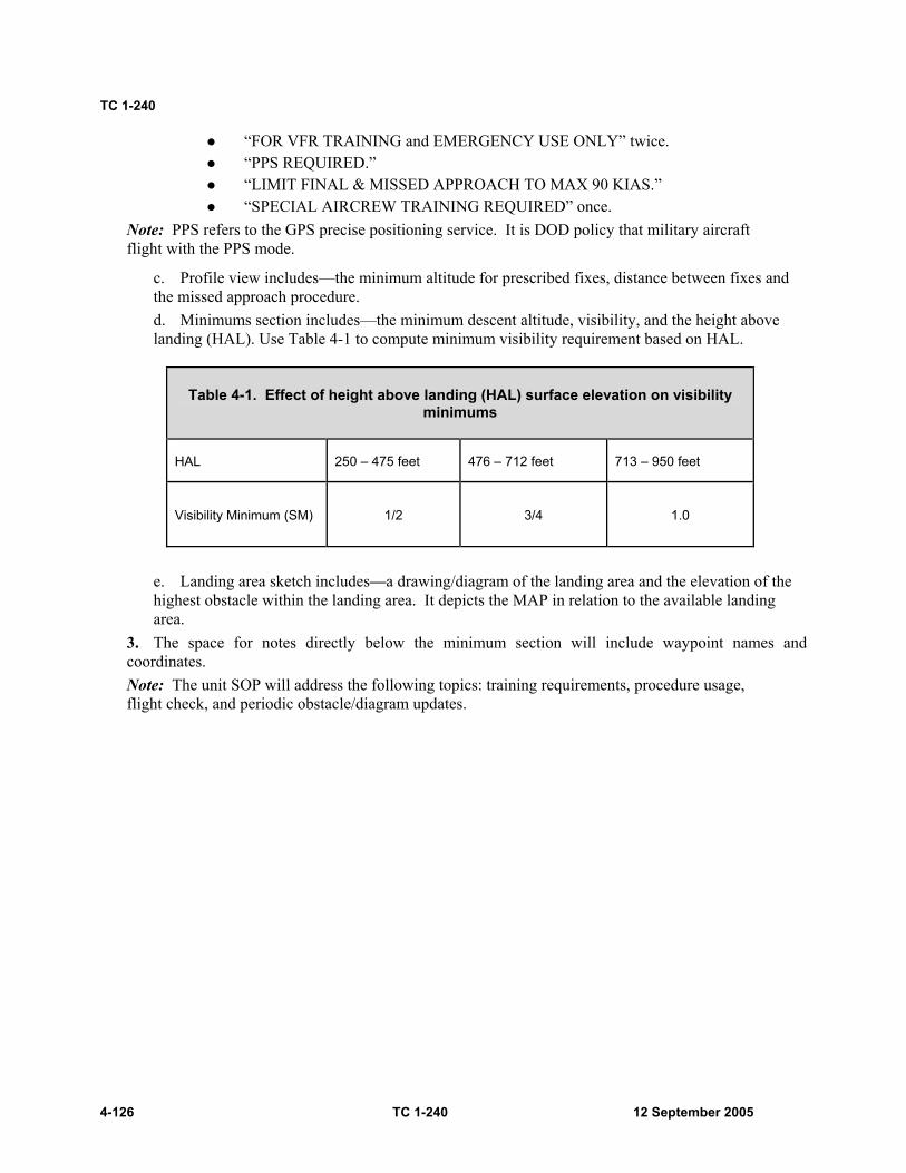
TC 1-240
4-126 TC 1-240 12 September 2005
“FOR VFR TRAINING and EMERGENCY USE ONLY” twice. “PPS REQUIRED.” “LIMIT FINAL & MISSED APPROACH TO MAX 90 KIAS.” “SPECIAL AIRCREW TRAINING REQUIRED” once.
Note: PPS refers to the GPS precise positioning service. It is DOD policy that military aircraft flight with the PPS mode.
c. Profile view includes—the minimum altitude for prescribed fixes, distance between fixes and the missed approach procedure. d. Minimums section includes—the minimum descent altitude, visibility, and the height above landing (HAL). Use Table 4-1 to compute minimum visibility requirement based on HAL.
Table 4-1. Effect of height above landing (HAL) surface elevation on visibility minimums
HAL 250 – 475 feet 476 – 712 feet 713 – 950 feet
Visibility Minimum (SM) 1/2 3/4 1.0
e. Landing area sketch includes—a drawing/diagram of the landing area and the elevation of the highest obstacle within the landing area. It depicts the MAP in relation to the available landing area.
3. The space for notes directly below the minimum section will include waypoint names and coordinates. Note: The unit SOP will address the following topics: training requirements, procedure usage, flight check, and periodic obstacle/diagram updates.

Crewmember Tasks
12 September 2005 TC 1-240 4-127
Figure 4-6. Sample of an emergency GPS recovery procedure diagram

TC 1-240
4-128 TC 1-240 12 September 2005
TRAINING AND EVALUATION REQUIREMENTS: 1. Training may be conducted academically. 2. Evaluation may be conducted academically.
REFERENCES: Unit SOP FM 1-240 FAA Handbook 8260.3 (TERPS Manual) FAA Order 8460.42A (Helicopter GPS Nonprecision Approach Criteria) FAA Order 7130.3 (Holding)

Crewmember Tasks
12 September 2005 TC 1-240 4-129
TASK 2052
Perform water bucket operations
WARNING
Never dump water onto ground personnel, as the water impact could result in injury.
Minimize hovering or flying slowly over fires. The rotor-wash fans the flames, which may cause more hazards to ground crews. When performing this task with cabin doors open, ensure that any personnel in the cabin area are wearing a safety harness secured to a tiedown ring or are sitting in a seat with seat belt fastened.
Note: The water bucket, when loaded, is a high-density load with favorable flight characteristics. Reduced velocity never to exceed (Vne), and bank angle limits must be kept in mind. Much of the mission profile is flown at high gross weight (GWT) and low airspeed. In addition, density altitude is greatly increased in the vicinity of a major fire. Performance planning must receive special emphasis.
CONDITIONS: In a CH-47 helicopter with an operational cargo hook, water bucket, required briefings, checks completed, and an air worthiness release.
STANDARDS: Appropriate common standards and the following additions/modifications: 1. Rated crewmember (RCM).
a. Conduct permission planning to determine fuel and bucket cinching requirements. Verify the aircraft will remain within GWT and center of gravity (CG) limitations for the duration of the flight. b. Conduct a thorough crew briefing. c. In conjunction with the nonrated crewmembers (NCMs), complete the required checks to ensure proper system operation before mission departure. d. Operate the water bucket system per manufacturer specifications. e. Recognize and respond to a water bucket system malfunction. f. Use proper dipping procedures for the water bucket type. g. Demonstrate knowledge of fire behavior and terminology. h. Hookup and hover.
(1) Maintain vertical ascent heading ±10 degrees. (2) Maintain altitude of load ± 10 feet above ground level (AGL), +3 foot. (3) Complete hover power checks.
i. En route, maintain load obstacle clearance (minimum 50 feet above highest obstacle [AHO]). j. Approach and water release.
(1) Evaluate fire/simulated fire for flight path and altitude requirements.
TC 1-240
4-130 TC 1-240 12 September 2005
(2) Maintain a constant approach angle to ensure that load safely clears obstacles. (3) Maintain ground track alignment with selected approach path. (4) Execute a smooth and controlled pass or termination over the intended point/area of water drop. (5) Deploy water as directed in proper location, orientation, and/or length.
2. NCM. a. In conjunction with RCMs, complete required water bucket checks to ensure proper system operation before mission departure and attach water bucket to the aircraft. b. Ensure that water bucket is configured for the condition and mode of flight. c. Recognize and respond to a water bucket system malfunction. d. Demonstrate knowledge of fire behavior and terminology.
DESCRIPTION: 1. Crew actions.
a. The pilot in command (PC) will conduct a thorough crew, external load, and water bucket briefing. The PC will ensure that all crewmembers are familiar with water bucket operations and emergency and communication procedures. He will ensure that DA Form 7382-R (Sling Load Inspection Record [LRA]) has been completed. He will confirm that required power is available by comparing the information from the performance planning card (PPC) to the hover power check. b. The pilot on the controls (P*) will remain focused primarily outside the aircraft throughout the maneuver. He will monitor altitude and avoid obstacles. c. The pilot not on the controls (P) will monitor the cockpit instruments and assist the P* in clearing the aircraft. The P will set cargo hook switches, as required, and should make all radio calls. When directed by the P* during the approach, the P will place the cargo hook master switch to the ARMED position. The NCM will release the water in accordance with the crew briefing. d. The P and NCM will assist in clearing the aircraft and will provide adequate warning of obstacles. They will announce when their attention is focused inside and again when attention is reestablished outside e. The NCM will remain focused primarily on the bucket. He will guide the P* during the bucket pickup, advise of the bucket condition in flight, provide directions and assistance when the water is dumped, and direct the P* when setting down the bucket. f. The NCM will advise the P* of any water bucket faults or failures. g. External load procedures in accordance with task 1063 will be used for normal external load techniques and load call outs. The NCM will advise the P* when the water bucket is in the water, filling, full, water deploying, and empty. He will instruct the P* as necessary to keep the electrical attachment assembly from entering the water.
2. Procedures. a. Preflight.
(1) The PC will analyze the mission using mission, enemy, terrain and weather, troops and support available, time available, civil considerations (METT-TC), and determine the amount of water required to conduct the mission and the initial profile to be used during the water emplacement. (2) The NCMs will ensure that the water bucket is installed and all installation checks are completed in accordance with the unit’s standing operating procedures (SOP).
Crewmember Tasks
12 September 2005 TC 1-240 4-131
(3) The crew will conduct the ground checks in accordance with the manufacturer’s procedures to confirm the proper operation of the water bucket before takeoff.
b. Hookup and hover. (1) Once the water bucket is placed on the ground beside the aircraft and all associated wiring is installed, place the cargo hook master switch in the ARM position. (2) Follow verbal signals from the NCM to hover over the water bucket. Apply control movements as necessary to remain vertically clear and centered over the water bucket. (3) Once in this position, smoothly apply thrust input until all slack is removed from the suspension cable. Maintain heading with pedals. (4) Apply additional thrust to raise the bucket to 10 feet above ground level (AGL). Monitor aircraft instruments to ensure that aircraft limitations are not exceeded.
c. Water pickup. Evaluation of the water pickup should include depth, obstacles, water current, and availability of hover references.
(1) Bambi bucket water pickup. (a) Arrive over water source with no forward ground speed and a bucket height of 10 feet above water level. (b) Slowly reduce the thrust and apply a slight amount of forward cyclic until the Bambi bucket contacts the water. Follow the NCM’s verbal guidance to remain centered over the bucket as it fills, applying cyclic, thrust, and pedals as necessary. (c) The pilot can vary the bucket’s capacity by varying the speed at which it is pulled from the water. A slow lift gives minimum fill. A fast lift gives maximum fill. (d) When the NCM indicates the bucket is ready (or full), increase the thrust-lever until all slack is removed from the suspension cable and the lip of the bucket is clear of the water, maintain heading with pedals. (e) Apply additional thrust to raise the filled bucket clear of the water’s surface to a height of 10 feet. Ensure that the bucket is holding the water and monitor aircraft instruments to ensure that aircraft limitations are not exceeded.
(2) Sims and simplex water pickup. (a) Arrive over water source with no forward ground speed and a bucket height of 10-feet above water level. (b) Ensure that bucket doors are open. (c) Slowly reduce the thrust until the bucket makes contact with the water. Once the bucket has submerged in the water, follow the NCM’s verbal guidance to remain centered over the bucket as it fills, applying cyclic, thrust, and pedals as necessary. (d) When the NCM indicates the bucket is full, he will close the bucket doors and ensure that the bucket is ready. (e) Then the P* can increase thrust until all slack is removed from the suspension cable and the lip of the bucket is clear of the water. Maintain heading with pedals. (f) Apply additional thrust to raise the filled bucket clear to the water’s surface to a height of 10 feet. Ensure that the bucket is holding the water and monitor aircraft instruments to ensure that aircraft limitations are not exceeded.
Note: Use the manufacturer’s recommended en route airspeeds for each type of water bucket. This prevents the buckets from twisting and pinching the cables.

TC 1-240
4-132 TC 1-240 12 September 2005
d. Takeoff. Establish a constant angle of climb that will permit safe obstacle clearance. When above 100 feet AGL or when clear of obstacles, adjust attitude and power as required to establish the desired rate of climb and airspeed. Smoothly adjust flight controls to prevent bucket oscillation.
Note: Ensure that the cargo hook master switch is in the ARMED position when operating at altitudes below 300 feet above highest obstacle (AHO) and in the OFF position above 300 feet AHO.
e. En route. Maintain the desired altitude, flight path, and airspeed. Make smooth control applications to prevent bucket oscillation. If an oscillation occurs, perform the same procedures as in task 1063. f. Approach and water release.
(1) The PC will determine the most appropriate height and speed for the pattern desired, or in accordance with the mission briefing. (2) Evaluation of the fire should include wind direction, velocity, terrain, and type of fire. Fires usually require a drop height of 100 to 200 feet AGL and a ground speed of 30 to 60 knots. (3) The aircraft’s ground track should be upwind and adjusted so the spray will provide maximum cooling to hot spots, as well as dampen unburned vegetation. Altitude and airspeed may be adjusted for fires of varying intensity and types. However, it must be noted that low, slow passes may tend to increase the fire’s intensity due to rotor down wash. (4) When the approach angle is intercepted, decrease the thrust-lever to establish the descent. When passing below 300 feet AGL, place cargo hook master switch in the ARM position. When reaching the desired airspeed and altitude, the recommended crew coordination terms for bucket operations are as follows:
(a) Approaching the target—“prepare to open the doors” (approximately 10 seconds out). (b) Over the target—“open doors.” (c) When the drop is complete—“close doors.”
Note: The NCM will advise the P* of the condition of the bucket and call out the water level while releasing water. The bucket manufacturer does not recommend dumping at airspeeds above 50 knots indicated airspeed (KIAS).
Note: There is a delay of appropriately 0.5 to 1.0 second between the activation of the dump switch and discharge of the water.
Note: Avoid flight over populated areas.
Water bucket preflight check. 1. Bottom of chain for tears in fabric. 2. Shackle and lockwire or tie-wrap condition. 3. Sidewall battens. 4. Diagonal M-straps connecting the suspension cables for wear. 5. Purse lines on the fabric dump valve. 6. Cinch strap belt—the end opposite the D-ring shall have a knot. 7. Suspension lines for frays, kinks, and conditions. 8. Ballast pouch in the bucket for rips or holes. 9. Control head for secure fittings. 10. Tripline for kinks, frays, or loose swages.
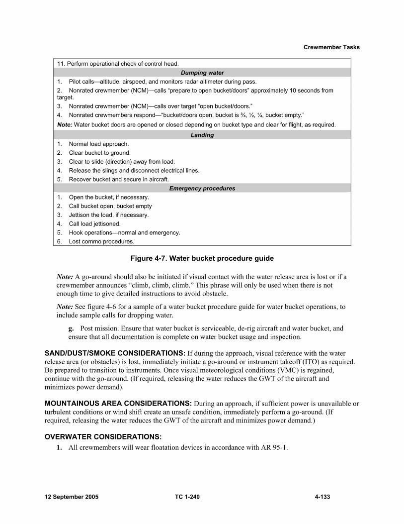
Crewmember Tasks
12 September 2005 TC 1-240 4-133
11. Perform operational check of control head. Dumping water
1. Pilot calls—altitude, airspeed, and monitors radar altimeter during pass. 2. Nonrated crewmember (NCM)—calls “prepare to open bucket/doors” approximately 10 seconds from target. 3. Nonrated crewmember (NCM)—calls over target “open bucket/doors.” 4. Nonrated crewmembers respond—“bucket/doors open, bucket is ¾, ½, ¼, bucket empty.” Note: Water bucket doors are opened or closed depending on bucket type and clear for flight, as required.
Landing 1. Normal load approach. 2. Clear bucket to ground. 3. Clear to slide (direction) away from load. 4. Release the slings and disconnect electrical lines. 5. Recover bucket and secure in aircraft.
Emergency procedures 1. Open the bucket, if necessary. 2. Call bucket open, bucket empty 3. Jettison the load, if necessary. 4. Call load jettisoned. 5. Hook operations—normal and emergency. 6. Lost commo procedures.
Figure 4-7. Water bucket procedure guide
Note: A go-around should also be initiated if visual contact with the water release area is lost or if a crewmember announces “climb, climb, climb.” This phrase will only be used when there is not enough time to give detailed instructions to avoid obstacle.
Note: See figure 4-6 for a sample of a water bucket procedure guide for water bucket operations, to include sample calls for dropping water.
g. Post mission. Ensure that water bucket is serviceable, de-rig aircraft and water bucket, and ensure that all documentation is complete on water bucket usage and inspection.
SAND/DUST/SMOKE CONSIDERATIONS: If during the approach, visual reference with the water release area (or obstacles) is lost, immediately initiate a go-around or instrument takeoff (ITO) as required. Be prepared to transition to instruments. Once visual meteorological conditions (VMC) is regained, continue with the go-around. (If required, releasing the water reduces the GWT of the aircraft and minimizes power demand).
MOUNTAINOUS AREA CONSIDERATIONS: During an approach, if sufficient power is unavailable or turbulent conditions or wind shift create an unsafe condition, immediately perform a go-around. (If required, releasing the water reduces the GWT of the aircraft and minimizes power demand.)
OVERWATER CONSIDERATIONS: 1. All crewmembers will wear floatation devices in accordance with AR 95-1.

TC 1-240
4-134 TC 1-240 12 September 2005
2. Overwater flight, at any altitude, is characterized by a lack of visual cues, and, therefore, has the potential of causing visual illusions. To minimize spatial disorientation, the crew should use radar altitude hold during overwater flight. 3. Be alert to any unannounced changes in the flight profile and be prepared to take immediate corrective actions. The radar altimeter low bug should be set to assist in altitude control. 4. Operations become increasingly more hazardous as references are reduced (open water versus a small lake), water state increases (calm to chop to breaking condition with increasing wave height), and visibility decreases (horizon becomes same color as water, water spray [or rain] on windshield, sunny mid-day versus twilight). 5. Hazards to flight such as harbor lights, buoys, wires, and birds must be considered during overwater flight. Note: There is a high probability the Doppler (AN/ASN-128) memory (MEM) indicator lamp will light while flying over smooth water. However, if the lamp remains on for over 10 minutes, over land or rough water, there is a malfunction in the Doppler set.
NIGHT OR NIGHT VISION GOGGLES CONSIDERATIONS: Not recommended. 1. During water bucket operations, the P*’s attention will be divided between the aircraft instruments (altitude and ground speed) and the outside. It is critical during night vision goggles (NVG) operations that the crewmembers’ focus be primarily outside to provide warning to the P* of obstacles (or hazards) during the entire operation. 2. Spatial disorientation can be overwhelming during overwater operations at night. Proper scanning techniques are necessary to avoid spatial disorientation.
TRAINING AND EVALUATION REQUIREMENTS: 1. Training will be conducted in the aircraft. 2. Evaluation will be conducted in the aircraft.
REFERENCES: Appropriate common references and the following: AR 70-62 FM 10-450-3 FM 20-32 Water bucket air worthiness release

Crewmember Tasks
12 September 2005 TC 1-240 4-135
TASK 2054
Perform fast-rope insertion and extraction
WARNING
Ensure that crewmembers in the cabin area are wearing a safety harness secured to a tiedown ring anytime the door or ramp is open. Also, ensure that all ropers are on the ground before any ropes are released.
CONDITIONS: In a CH-47 helicopter with fast-rope insertion and extraction (FRIES) equipment installed.
STANDARDS: Appropriate common standards and the following additions/modifications: 1. Rated crewmember (RCM).
a. Conduct a thorough crew and passenger briefing. b. Maintain entry altitude as directed ±10 feet. c. Maintain entry airspeed of 80 knots indicated airspeed (KIAS) ±5 KIAS. d. Maintain track aligned with landing direction. e. Perform a smooth, controlled termination to a hover over the insertion point. Deceleration attitude is not to exceed 20 degrees. f. Maintain appropriate hover height ±5 feet, not to exceed rope height.
2. Nonrated crewmember (NCM). Ensure that the aircraft is configured for FRIES operations per TC 21-24.
DESCRIPTION: 1. Crew actions.
a. The pilot in command (PC) will conduct a crew and passenger briefing and ensure that personnel are familiar with normal and emergency procedures. He will ensure that the aircraft is rigged. b. The pilot on the controls (P*) will remain focused primarily outside the aircraft throughout the maneuver and will announce when he begins the maneuver. The P* will also announce the intended point of insertion. c. The pilot not on the controls (P) and NCM will assist in clearing the aircraft and will provide adequate warning of obstacles. They will also assist the P* in maintaining a stable hover. The NCM will inspect the rigging to ensure that the aircraft is configured for fast rope operations.
TC 1-240
4-136 TC 1-240 12 September 2005
2. Procedures. a. To perform a FRIES assault, execute a visual meteorological conditions (VMC) approach to the insertion point. On final approach, adjust airspeed and altitude during the approach to stop over the insertion point at a predetermined hover height (not to exceed rope length). At a stabilized hover, the FRIES operation begins. Remain over the area at a stabilized hover until all ropers and ropes are clear. b. After ropers are clear, crewmembers will pull the ropes back inside the aircraft or release them by pulling the locking device and detaching the rope. Keep the aircraft stationary until the “ropes clear” signal is given.
Note: Task 1038 and task 2036 contain procedures that may be used in performing this task.
Note: A high hover, especially if a 90-foot rope is used, may cause the loss of all visual hover cues.
Note: See figure 4-8 for a sample FRIES checklist.
NIGHT OR NIGHT VISION DEVICE CONSIDERATIONS: Due to loss of forward references during decelerations, recommend maximum pitch attitude of 15 degrees. Use infrared (IR) bypass band filter searchlight, as necessary, to maintain position and hover altitude for night vision goggles (NVG) operations. Proper scanning techniques are necessary to detect aircraft drift and to avoid spatial disorientation.
TRAINING AND EVALUATION REQUIREMENTS: 1. Training will be conducted in the aircraft. 2. Evaluations will be conducted in the aircraft.
REFERENCES: Appropriate common references and the following: FRIES air worthiness release TC 21-24
Note: Headquarters, Department of the Army (HQDA) policy specifies that FRIES is not approved for Army-wide use and names the Commanding General, United States Army Special Operations Command (CG USASOC), as the executive agent for FRIES doctrine. The use of FRIES is restricted to special operations forces, pathfinders, long-range surveillance units, and HQDA-approved schools with a USASOC-approved FRIES program on instruction. Request for other units to conduct FRIES operations will be submitted to Commander, USASOC, ATTN: AOOP-TRS, Fort Bragg, NC.
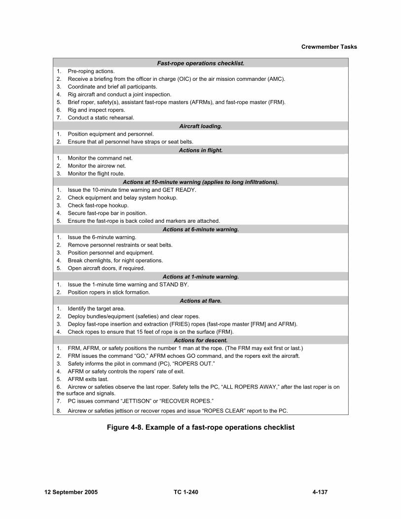
Crewmember Tasks
12 September 2005 TC 1-240 4-137
Fast-rope operations checklist. 1. Pre-roping actions. 2. Receive a briefing from the officer in charge (OIC) or the air mission commander (AMC). 3. Coordinate and brief all participants. 4. Rig aircraft and conduct a joint inspection. 5. Brief roper, safety(s), assistant fast-rope masters (AFRMs), and fast-rope master (FRM). 6. Rig and inspect ropers. 7. Conduct a static rehearsal.
Aircraft loading. 1. Position equipment and personnel. 2. Ensure that all personnel have straps or seat belts.
Actions in flight. 1. Monitor the command net. 2. Monitor the aircrew net. 3. Monitor the flight route.
Actions at 10-minute warning (applies to long infiltrations). 1. Issue the 10-minute time warning and GET READY. 2. Check equipment and belay system hookup. 3. Check fast-rope hookup. 4. Secure fast-rope bar in position. 5. Ensure the fast-rope is back coiled and markers are attached.
Actions at 6-minute warning. 1. Issue the 6-minute warning. 2. Remove personnel restraints or seat belts. 3. Position personnel and equipment. 4. Break chemlights, for night operations. 5. Open aircraft doors, if required.
Actions at 1-minute warning. 1. Issue the 1-minute time warning and STAND BY. 2. Position ropers in stick formation.
Actions at flare. 1. Identify the target area. 2. Deploy bundles/equipment (safeties) and clear ropes. 3. Deploy fast-rope insertion and extraction (FRIES) ropes (fast-rope master [FRM] and AFRM). 4. Check ropes to ensure that 15 feet of rope is on the surface (FRM).
Actions for descent. 1. FRM, AFRM, or safety positions the number 1 man at the rope. (The FRM may exit first or last.) 2. FRM issues the command “GO,” AFRM echoes GO command, and the ropers exit the aircraft. 3. Safety informs the pilot in command (PC), “ROPERS OUT.” 4. AFRM or safety controls the ropers’ rate of exit. 5. AFRM exits last. 6. Aircrew or safeties observe the last roper. Safety tells the PC, “ALL ROPERS AWAY,” after the last roper is on the surface and signals. 7. PC issues command “JETTISON” or “RECOVER ROPES.”
8. Aircrew or safeties jettison or recover ropes and issue “ROPES CLEAR” report to the PC.
Figure 4-8. Example of a fast-rope operations checklist

TC 1-240
4-138 TC 1-240 12 September 2005
TASK 2056
Perform rappelling operations
WARNING
Ensure that the rappel master is secured to a tiedown ring. Also ensure that all ropers are on the ground before any ropes are released. If the roper’s equipment becomes fouled on the ramp or probe, ensure that the roper is “locked in” on the rope before freeing the equipment. Maintain visual contact with the roper until equipment is freed.
CAUTION Weight bags must remain attached to any rope that is retrieved into the aircraft.
CONDITIONS: In a CH-47 properly configured and hover out-of-ground effect (OGE) power is available.
STANDARDS: Appropriate common standards and the following additions/modifications: 1. Rated crewmember (RCM).
a. Conduct a thorough crew and passenger briefing. b. Maintain appropriate hover altitude ±5 feet. c. Maintain ropes in continuous contact with the ground. d. Do not allow drift to exceed 5 feet from the intended hover point. e. Hover symbology selected at pilot on the controls (P*) station.
2. Nonrated crewmember (NCM) general duties. a. Properly clear aircraft and make rope calls informing pilots of status of ropes and passengers. b. Check that all equipment is installed properly. c. Ensure that load/passengers weight does not exceed aircraft limitations. d. Ensure that equipment is rigged properly when performing equipment drops. e. Ensure that ropes are on ground before releasing ropers. f. Use proper terminology.
Crewmember Tasks
12 September 2005 TC 1-240 4-139
DESCRIPTION: Note: The pilot in command (PC) will ensure that the intended P* for the maneuver is assigned the seat position that will afford the greatest visibility for conducting the maneuver.
1. Crew actions. a. PC conducts (or directs) a crewmember to conduct a crew and passenger briefing and ensure that personnel are familiar with normal and emergency procedures. NCM will verify rope lengths with supportive unit and inform the PC. NCM will inspect rigging to ensure that the aircraft is configured properly for rappelling operations. PC confirms the ropes are rigged properly. b. P* remains focused primarily outside the aircraft throughout the maneuver and will announce when he begins the maneuver. P* will also announce the intended point of insertion and pass the rappelling execution command to the NCMs. c. Pilot not on the controls (P) and NCM assist in clearing the aircraft and provide adequate warning of obstacles. They will also assist P* in maintaining a stable hover. d. NCMs will determine who will make specific calls and inform the pilots (normally, right ramp makes primary calls). NCMs will be responsible for passing the 10-, 6-, 3-, and 1-minute calls. The right ramp usually will be responsible for making the primary rope calls. e. NCMs will use pre-established procedures and communications, including hand and arm signals, with the fast rope master. NCMs will deploy, release, or retrieve the ropes. f. NCMs will inform PC once all ropes are clear of the aircraft, have been retrieved back into the aircraft, or are secure during elevator training.
2. Procedures. a. Ten minutes before estimated time of arrival (ETA), the P will announce, “TEN MINUTES OUT.” Each NCM or rope master (RM) will inform the passengers at his station of the timed call and announce when his station is ready, “AFT READY,” “FWD READY.” The same procedures will be conducted at the 6-, 3-, and 1-minute timed calls. At night, the NCMs at each station will break the chemlights attached to the ropes by the 6-minute call. b. When the objective is sighted and the P* judges that he can initiate the maneuver to stop at a stabilized hover over the target point, the P* will apply aft cyclic and adjust thrust, as necessary, to stabilize at a hover over the intended target. If the closure rate to the intended hover point is too fast, the P* may adjust the aircraft attitude, but will not exceed 20 degrees nose high. Maintain appropriate roping height ±5 feet. The P should call out aircraft parameters, attitude, and radar height during the maneuver. NCMs will get into roping position by 1-minute out. c. When stabilized at a hover, the right ramp should announce “OVER THE TARGET,” the P* will call “ROPES, ROPES, ROPES.” The NCM at each station will deploy, direct, or help ropes when the ropes have been deployed. The right ramp should announce “AFT ROPES OUT” (if applicable) and the right gun will announce “FWD ROPES OUT” (if applicable) when personnel/equipment exits the aircraft. The right ramp should announce, “AFT ROPING IN PROGRESS,” the forward (FWD) crew chief (CE) will announce “FWD ROPING IN PROGRESS” (if applicable). Although all NCMs are responsible for maintaining the aircraft at a stabilized hover with minimum drift, and clear of obstructions, the right ramp should make the primary calls.

TC 1-240
4-140 TC 1-240 12 September 2005
d. When personnel/equipment are clear, each NCM at a station will visually confirm personnel/equipment are clear and release (or retrieve) ropes as briefed. The right ramp should announce, “AFT ROPES RELEASED, AFT READY”; the right gun will announce, “FWD ROPES RELEASED (if applicable), FWD READY, CLEARED FOR FLIGHT.” e. The P* will announce his intent to depart the target area. He will maintain outside visual reference and depart the area maintaining obstacle clearance along his intended ground track. f. Standard terminology will be used during rappelling insertion (see table 4-2).
Table 4-2. Standard rappelling insertion terminology.
Speaker Reason Statement
From pilot on the controls (P*) to the crew. Indicates ready for rope deployment. * “Ropes, ropes, ropes”
From flight engineer (FE)/crew chief (CE) to pilots.
Indicates the ropes are deployed over target. * “Ropes out”
From flight engineer (FE)/crew chief (CE) to pilots. Indicates the first roper is exiting aircraft. * “Roping in progress”
From flight engineer (FE)/crew chief (CE) to pilots. Indicates the ropes have been cut away. * “Ropes released”
From flight engineer (FE)/crew chief (CE) to pilots.
Indicates the ropes have been pulled back into the aircraft and are secured. * “Ropes retrieved”
From flight engineer (FE)/crew chief (CE) to pilots. Hold position. “Hold”
From flight engineer (FE)/crew chief (CE) to pilots.
Indicates direction in which to reposition the aircraft.
“Move” (left, right, forward, back)
From flight engineer (FE)/crew chief (CE) to pilots.
Indicates all ropers are clear from the aircraft. “Aft ready, forward ready”
Forward crew chief (FWD CE) Will be the only one to say this. “Clear for flight” From flight engineer (FE)/crew chief (CE) to pilots.
Indicates a problem at a station; all roping ceases until problem is rectified. “Stop stick”
From flight engineer (FE)/crew chief (CE) to pilots. Indicates aircraft is over the target. “Over the target”
* Aft, forward from crew chief (CE) to pilots, will preclude calls to indicate appropriate station.
TRAINING AND EVALUATION REQUIREMENTS: 1. Training will be conducted in the aircraft.
a. Pilot training does not require ropers. b. NCM training requires personnel/gear to go down the ropes.
2. Evaluations will be conducted in the aircraft. a. Pilot evaluations do not require ropers. b. NCM evaluations require personnel/gear to go down the ropes.
REFERENCES: Appropriate common references.

Crewmember Tasks
12 September 2005 TC 1-240 4-141
TASK 2058
Perform special patrol infiltration/exfiltration
WARNING
Ensure that the special patrol infiltration/exfiltration (SPIES) master and crew chief wear a safety harness secured to a tiedown ring anytime the door or ramp is opened.
CAUTION Ensure that SPIES rope remains secured to the cargo floor until the aircraft has landed. If recovery of SPIES rope is impossible, execute a roll-on landing to avoid entanglement in the rotor system.
CONDITIONS: In a CH-47 helicopter with special patrol infiltration/exfiltration (SPIES) equipment installed and SPIES crew assigned.
STANDARDS: Appropriate common standards and the following additions/modifications: 1. Rated crewmember (RCM).
a. Conduct a thorough crew and passenger safety briefing. b. Maintain obstacle clearance between team members, obstacles, and the ground. c. Maintain airspeed ±5 knots. (Maximum airspeed with team members attached is 70 knots indicated airspeed [KIAS] in moderate climates and 50 KIAS in cold climates.) d. Bank angle not to exceed 30 degrees.
2. Nonrated crewmember (NCM). Ensure that the aircraft is prepared for SPIES operations per TC 21-24 and the unit’s standing operating procedures (SOP).
DESCRIPTION: 1. Crew actions.
a. The pilot in command (PC) will conduct a thorough crew briefing and ensure that all crewmembers are familiar with SPIES operations, emergency, and communication procedures. He will ensure that the aircraft is rigged. b. The pilot on the controls (P*) will remain focused primarily outside the aircraft throughout the maneuver to ensure aircraft control and obstacle avoidance. He will announce the intended point of extraction and remain centered over the target, incorporating corrections from the SPIES master as required.

TC 1-240
4-142 TC 1-240 12 September 2005
c. The pilot not on the controls (P) and NCM will assist in clearing the aircraft and will provide adequate warning of obstacles. They will assist the P* during the pickup phase of the operation. They will advise the P* when the slack is out of the ropes, and when the SPIES members are off the ground and above highest obstacle (AHO). During forward flight, the NCM must constantly monitor the SPIES members and keep the P* informed of their stability and clearance.
2. Procedures. a. Establish communications with personnel at extraction site. The approach should be terminated into the wind at a 90-foot hover. Normal length of SPIES ropes is 120 feet. Once stabilized over the extraction site, the NCM (when authorized by the PC) will throw out the deployment bags. The NCM will inform the P* when all ropers are ready and hook-up is complete. The NCM verifies that extraction harnesses are secure and safe as the ropers are lifted off the ground. b. Ascend at a rate that will ensure the safety of the SPIES members. To avoid jerking the SPIES members off the ground, the slack in the ropes must be removed cautiously. Do not start forward flight until all obstacles are cleared. c. Maximum en route airspeed will not be faster than 70 KIAS in moderate climates and 50 KIAS in cold climates while team members are attached to the SPIES rope. Maximum aircraft bank angle will be no greater than 30 degrees. During forward flight, the NCM must constantly monitor the SPIES members and keep the P* informed of their stability. It may be necessary to reduce airspeed if SPIES personnel begin to spin or if the cone angle exceeds 30 degrees. d. Upon arrival at the dismount area, transition to hovering flight at an altitude of 250 feet above ground level (AGL). Start vertical descent with the rate not to exceed 100 foot per minute (at touchdown). Maintain a stable hover until SPIES team members clear the rope.
OVERWATER CONSIDERATIONS: 1. The SPIES is suitable for extracting teams from the water. For this procedure, three inflatable life vests (or any type of floatation device) are tied to the SPIES rope to provide buoyancy for the rope while in the water. 2. Takeoff, en route, and landing are the same for water as over land. The dismounting procedures differ when landing on a ship. Once onboard, the team members take their orders from personnel in charge of the deck. 3. All crewmembers will wear floatation devices in accordance with AR 95-1. 4. Overwater flight, at any altitude, is characterized by a lack of visual cues, and, therefore, has the potential of causing visual illusions. To minimize spatial disorientation, the crew should use radar altitude hold during overwater flight. 5. Be alert to any unannounced changes in the flight profile and be prepared to take immediate corrective actions. The radar altimeter low bug should be set to assist in altitude control. 6. Operations become increasingly more hazardous as references are reduced (open water versus a small lake), water state increases (calm to chop to breaking condition with increasing wave height), and visibility decreases (horizon becomes same color as water, water spray [or rain] on windshield, sunny mid-day versus twilight). 7. Hazards to flight such as harbor lights, buoys, wires, and birds must be considered during overwater flight. Note: There is a high probability the Doppler (AN/ASN-128) memory (MEM) indicator lamp will light while flying over smooth water. However, if the lamp remains on for over 10 minutes, over land or rough water, there is a malfunction in the Doppler set.
Crewmember Tasks
12 September 2005 TC 1-240 4-143
NIGHT OR NIGHT VISION GOGGLES CONSIDERATIONS: 1. For unaided night flight, the landing light and searchlight should be operational. If a night vision goggles (NVG) filter is installed, it should be removed. 2. Due to the high hover altitude of SPIES operations, it is very difficult to determine altitudes and relative position over the ground. The barometric altimeter is not reliable for this maneuver, but can be used as an aid to help maintain a constant altitude. References (such as tops of trees, lights, and man-made objects) can be used to help prevent drift by lining up the objects and maintaining their relative position once the aircraft is at a stable altitude. 3. If possible, select an area with good contrast and several reference points at the same or greater height as the SPIES hover altitude. Proper scanning techniques are necessary to avoid spatial disorientation. 4. Spatial disorientation can be overwhelming during nighttime overwater operations. If there are visible lights on the horizon or if the shoreline can be seen, the pilot may opt to approach the survivor(s) so the aircraft is pointed toward these references, if the wind permits. If no other references exist, deploy chemlights to assist in maintaining a stable hover.
TRAINING AND EVALUATION REQUIREMENTS: 1. Training will be conducted in the aircraft. 2. Evaluation will be conducted in the aircraft.
REFERENCES: Appropriate common references and the following: SPIES air worthiness release

TC 1-240
4-144 TC 1-240 12 September 2005
TASK 2059
Perform rescue-hoist/winch operations
WARNING
Ensure that crewmembers in the cabin area are wearing a safety harness secured to a tiedown ring anytime the upper cabin door and rescue hatch door are open. The crewmember riding the hoist will be secured either to the aircraft or to the jungle penetrator. Ensure that cable touches the ground or the water before ground personnel touch the cable. Cable will be charged with in excess of 300,000 volts of static electricity.
CAUTION Care must be taken not to snag terrain features or foliage with the rescue-hoist cable. This may result in exceeding the 600-pound structural limitation of the overhead pulley support.
CONDITIONS: In a CH-47 helicopter equipped with a rescue-hoist/winch system.
STANDARDS: Appropriate common standards and the following additions/modifications: 1. Rated crewmember (RCM).
a. Conduct a thorough crew and passenger safety briefing. b. Perform rescue-hoist procedures per TM 1-1520-240-10/TM 1-1520-240-CL. c. Perform rescue-hoist/winch procedures per TM 1-1520-240-10/TM 1-1520-240-CL, FM 8-10-6, TC 1-201, and the unit’s standing operating procedure (SOP). d. Maintain appropriate hover altitude ±5 feet. e. Do not allow drift to exceed ±5 feet from the intended hover point.
2. Nonrated crewmember (NCM). a. Perform a preflight inspection of the rescue-hoist/winch per TM 1-1520-240-10/ TM 1-1520-240-CL and the unit SOP. b. Ensure that the crew, passengers, cargo, and mission equipment are secured. c. Operate the rescue-hoist/winch.
Crewmember Tasks
12 September 2005 TC 1-240 4-145
DESCRIPTION: 1. Crew actions.
a. Rescue hoist operations. (1) The pilot in command (PC) will conduct a thorough crew briefing and ensure that all crewmembers are familiar with rescue-hoist operations, emergency procedures, communication procedures, lowering the flight medic, and lifting the patient off the ground using the hoist or aircraft. He will also ensure that all crewmembers understand “CUT CABLE” procedures. (2) The pilot on the controls (P*) will remain focused primarily outside the aircraft throughout the maneuver to ensure aircraft control and obstacle avoidance. He will announce the intended point of hover and remain centered over the target, incorporating corrections from the NCM. (3) The pilot not on the controls (P) and NCM will assist in clearing the aircraft and will provide adequate warning of obstacles. They will also assist the P* in maintaining a stable hover by providing the P* with information regarding the drift of the aircraft. The P will also monitor cockpit indications. The P will be able to operate the control panel for the rescue-hoist if necessary. (4) The NCM will ensure that the hoist is configured and will ensure that all lifting devices (such as Jungle penetrator, SKED/Stokes litter, and survivor’s slings) are secured in the aircraft before takeoff. (5) The NCM will ensure that the winch is configured for rescue-hoist operations and the appropriate write-up is entered on DA Form 2408-13-1 (Aircraft Maintenance and Inspection Record) for the mid-hook being removed in accordance with TM 1-1520-240-10. (6) The NCM will conduct the hoist operation per TC 1-201, TM 1-1520-240-10/ TM 1-1520-240-CL, and the unit SOP.
b. Cargo winch operations. (1) The NCM will ensure that the winch is configured for rescue-hoist operations and the appropriate write-up is entered on DA Form 2408-13-1 for the mid-hook being removed in accordance with TM 1-1520-240-10. (2) The NCM will conduct the rescue-hoist operation per TC 1-201, TM 1-1520-240-10/ TM 1-1520-240-CL, and the unit SOP.
2. Procedures. a. General recovery procedures over land.
(1) Crewmembers alerted approximately 5 minutes before arrival at pickup site. (2) Crewmembers complete all required checks (such as rescue-hoist control panel switches set, hoist circuit breakers set, internal communications system [ICS] selector switches set, and crewmembers reposition for hoist operations). (3) Make the approach into the wind if possible and plan to terminate the approach at an altitude that will clear the highest obstacle. (4) Select an appropriate reference point to maintain heading and position over the ground. Once stabilized over pickup site, perform hoist operations in accordance with FM 8-10-6, TC 1-201, TM 1-1520-240-10/TM 1-1520-240-CL, and the unit SOP.

TC 1-240
4-146 TC 1-240 12 September 2005
b. Inert patient recovery. (1) General format is the same as over land except the NCM/medical officer (MO) is lowered on the hoist and secures the patient to the recovery device. (2) Before deploying, all crewmembers will be briefed on method of recovery (simultaneous or singular recovery of the patient and MO) and a radio communications check should be made between the pilot and NCM/MO.
c. General recovery procedures overwater. (1) General format is the same as over land except a smoke device may be used to determine wind direction and velocity. Terminate the approach at a 100-foot hover, 20 feet before reaching the patient. Deploy the recovery device and allow it to contact the water before reaching the patient. (2) All crewmembers will wear floatation devices. Operations become increasingly more hazardous as references are reduced (open water versus a small lake or ship versus small boat), sea state increases (calm to chop to breaking condition with increasing wave height), and visibility decreases (horizon becomes same color as water, water spray or rain on windshield, sunny mid-day versus twilight).
Note: The NCM will advise the P* when the person/equipment is in position on the jungle penetrator. The NCM will perform hoist operations in accordance with the standard words and phrases in accordance with unit SOP. The NCM will secure jungle penetrator or stokes litter upon completion of the hoisting operation. Should difficulty in maintaining a stable hover occur, the NCM will extend additional cable as slack to preclude inadvertent jerking of the cable.
OVERWATER CONSIDERATIONS: 1. All crewmembers will wear floatation devices in accordance with AR 95-1. 2. Overwater flight, at any altitude, is characterized by a lack of visual cues, and, therefore, has the potential of causing visual illusions. To minimize spatial disorientation, the crew should use radar altitude hold during overwater flight. 3. Be alert to any unannounced changes in the flight profile and be prepared to take immediate corrective actions. The radar altimeter low bug should be set to assist in altitude control. 4. Operations become increasingly more hazardous as references are reduced (open water versus a small lake), water state increases (calm to chop to breaking condition with increasing wave height), and visibility decreases (horizon becomes same color as water, water spray [or rain] on windshield, sunny mid-day versus twilight). 5. Hazards to flight such as harbor lights, buoys, wires, and birds must be considered during overwater flight. Note: There is a high probability the Doppler (AN/ASN-128) memory (MEM) indicator lamp will light while flying over smooth water. However, if the lamp remains on for over 10 minutes, over land or rough water, there is a malfunction in the Doppler set.
NIGHT OR NIGHT VISION GOGGLES CONSIDERATIONS: Use proper scanning techniques to avoid spatial disorientation.
1. For unaided night flight, the landing light and searchlight should be operational. If a night vision goggles (NVG) filter is installed, it should be removed.

Crewmember Tasks
12 September 2005 TC 1-240 4-147
2. When NVGs are used, hovering with minimum drift is difficult and requires proper scanning techniques and crewmember coordination. If possible, use an area with adequate ground contrast and reference points. 3. Visual obstacles such as shadows should be treated the same as physical obstacles. 4. Spatial disorientation can be overwhelming during nighttime overwater operations. If there are visible lights on the horizon or if the shoreline can be seen, the pilot may opt to approach the survivor(s) so the aircraft is pointed toward these references, if the wind permits. If no other references exist, deploy chemlights to assist in maintaining a stable hover.
TRAINING AND EVALUATION REQUIREMENTS: 1. Training will be conducted in the aircraft. 2. Evaluation will be conducted in the aircraft.
REFERENCES: Appropriate common references and the following: FM 8-10-6 TM 55-4240-284-12&P
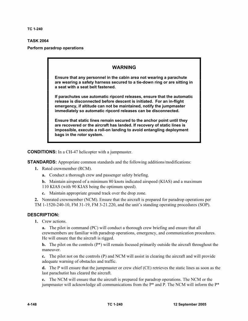
TC 1-240
4-148 TC 1-240 12 September 2005
TASK 2064
Perform paradrop operations
WARNING
Ensure that any personnel in the cabin area not wearing a parachute are wearing a safety harness secured to a tie-down ring or are sitting in a seat with a seat belt fastened.
If parachutes use automatic ripcord releases, ensure that the automatic release is disconnected before descent is initiated. For an in-flight emergency, if altitude can not be maintained, notify the jumpmaster immediately so automatic ripcord releases can be disconnected.
Ensure that static lines remain secured to the anchor point until they are recovered or the aircraft has landed. If recovery of static lines is impossible, execute a roll-on landing to avoid entangling deployment bags in the rotor system.
CONDITIONS: In a CH-47 helicopter with a jumpmaster.
STANDARDS: Appropriate common standards and the following additions/modifications: 1. Rated crewmember (RCM).
a. Conduct a thorough crew and passenger safety briefing. b. Maintain airspeed of a minimum 80 knots indicated airspeed (KIAS) and a maximum 110 KIAS (with 90 KIAS being the optimum speed). c. Maintain appropriate ground track over the drop zone.
2. Nonrated crewmember (NCM). Ensure that the aircraft is prepared for paradrop operations per TM 1-1520-240-10, FM 31-19, FM 3-21.220, and the unit’s standing operating procedures (SOP).
DESCRIPTION: 1. Crew actions.
a. The pilot in command (PC) will conduct a thorough crew briefing and ensure that all crewmembers are familiar with paradrop operations, emergency, and communication procedures. He will ensure that the aircraft is rigged. b. The pilot on the controls (P*) will remain focused primarily outside the aircraft throughout the maneuver. c. The pilot not on the controls (P) and NCM will assist in clearing the aircraft and will provide adequate warning of obstacles and traffic. d. The P will ensure that the jumpmaster or crew chief (CE) retrieves the static lines as soon as the last parachutist has cleared the aircraft. e. The NCM will ensure that the aircraft is prepared for paradrop operations. The NCM or the jumpmaster will acknowledge all communications from the P* and P. The NCM will inform the P*
Crewmember Tasks
12 September 2005 TC 1-240 4-149
or P when all parachutists have exited the aircraft and when the deployment bags have been recovered.
2. Procedures. a. Maintain altitude, airspeed, and ground track as determined during premission planning and jumpmaster's instructions. b. Perform in-flight procedures per FM 31-19, FM 3-21.220, FM 3-21.220, and unit SOP. c. The CE will—
(1) Remove the ramp extensions and ensure that the ramp and cabin floor are clean and dry. (2) Install the static line anchor cable and retriever, if needed, per FM 1-400 and TM 1-1520-240-10. (3) Ensure that the static line anchor cable does not sag more than 6 inches and will check the turnbuckle for safety. (4) Pad and tape all clamps on the cable with cellulose wadding and masking tape. (5) Rig the troop seats for the mission; adjust the seat backs, if required, and ensure that airsick bags are available. (6) Lower the ramp to a 3-degree below level position before the crew begins the drop.
d. The crew will conduct the paradrop per the procedures covered in the briefing and the references listed below. e. The PC will check that the jumpmaster (or CE) retrieves the static lines as soon as the last parachutist has cleared the aircraft.
TRAINING AND EVALUATION REQUIREMENTS: 1. Training will be conducted in the aircraft. 2. Evaluation will be conducted in the aircraft.
REFERENCES: Appropriate common references and the following: FAR Part 105 FM 3-21.220 FM 31-19
TC 1-240
4-150 TC 1-240 12 September 2005
TASK 2066
Perform extended range fuel system procedures
CONDITIONS: In a CH-47 helicopter with extended range fuel system (ERFS) installed or academically. Note: ERFS refers to the ERFS I or ERFS II systems.
STANDARDS: Appropriate common standards and the following additions/modifications: 1. Rated crewmember (RCM).
a. Perform procedures and checks per TM 1-1520-240-10, TM 55-1560-307-13/ TM 55-1560-307-13-P, or TM 1-1560-312-10. b. Operate aircraft within center of gravity (CG)/gross weight (GWT) limitations.
2. Nonrated crewmember (NCM). a. Configure aircraft in accordance with TM 55-1560-307-13&P or TM 1-1560-312-10. b. Complete all before flight, in-flight, and preflight duties in accordance with TM 1-1520-240-10 and TM 55-1560-307-13&P, or TM 1-1560-312-10. c. Perform all fuel servicing in accordance with TM 1-1520-240-10, TM 55-1560-307-13&P, TM 1-1560-312-10, FM 3-04.111, and FM 10-67-1. d. After ERFS operation, remove and store ERFS in accordance with TM 55-1560-307-13&P or TM 1-1560-312-10.
DESCRIPTION 1. Crew actions.
a. The pilot in command (PC) will conduct a thorough mission briefing and ensure that all personnel are familiar with normal and emergency procedures. b. The PC will ensure that a preflight of the ERFS is conducted before flight. c. The pilot not on the controls (P) will ensure that all main tanks are on and all auxiliary pumps are off when ERFS transfer to the main tanks is desired. d. The P will monitor the main fuel indicators and ensure that fuel management procedures are conducted. e. The NCM will ensure that the system is operational before flight, monitor the fuel management panel in flight, and ensure that ERFS tanks and associated equipment are inspected for proper operation and that no leaks are evident. f. The NCM will manage the tank fuel transfer sequence as directed by the PC, inform the crew when the low-level warning lights illuminate, close the dump valve when empty, and inform the crew of any unusual or emergency situations.

Crewmember Tasks
12 September 2005 TC 1-240 4-151
2. Procedures. a. Each crewmember will complete all required inspections pertaining to his section of TM 1-1520-240-10, TM 55-1560-307-13&P, or TM 1-1560-312-10, and the unit’s standing operating procedures (SOP). b. NCMs will ensure that no fuel leaks are evident during servicing, preflight, and in-flight operation of the ERFS. If leaks are evident, stop servicing immediately and refer to the appropriate maintenance manuals. c. After the ERFS tank system is serviced, a fuel sample will be taken from the sample area of each tank. If contamination is found, conduct contamination inspection procedures in accordance with TM 55-1560-307-13&P, TM 1-1560-312-10, FM 3-04.111, and FM 10-67-1. Ensure that a fuel sample has been taken in accordance with the appropriate manuals. d. Each crewmember will ensure that all safety and operational procedures are conducted in accordance with TM 55-1560-307-13&P or TM 1-1560-312-10.
NIGHT OR NIGHT VISION GOGGLES CONSIDERATIONS: If time permits, accomplish servicing and preflight inspections during daylight hours. During the hours of darkness, use a flashlight with an unfiltered lens to supplement available lighting. Hydraulic leaks, oil leaks, and other defects are difficult to see using a flashlight with a colored lens.
TRAINING AND EVALUATION REQUIREMENTS: 1. Training will be conducted in the aircraft. 2. Evaluations will be conducted in the aircraft.
REFERENCES: Appropriate common references and the following: FM 3-04.111 FM 10-67-1 TM 1-1520-240-PMD TM 1-1560-312-10 TM 55-1560-307-13&P

TC 1-240
4-152 TC 1-240 12 September 2005
TASK 2068
Perform shipboard operations
WARNING
Do not move the cyclic with the pitch and roll of the ship. Do not allow the rotor to dip down to a low position, as it could be fatal to deck crews and those exiting the aircraft.
CONDITIONS: In a CH-47 helicopter.
STANDARDS: Appropriate common standards and the following additions/modifications: 1. Rated crewmember (RCM).
a. Comply with arrival and departure and landing signal enlisted (LSE)/controller instructions. b. Set parking brakes before landing. c. Ensure a green deck before landing. d. Perform a visual meteorological conditions (VMC) approach. e. Perform a VMC takeoff.
2. Nonrated crewmember (NCM). a. Call the aircraft over the landing area. b. Ensure that all landing gear is cleared onto or off the deck. c. Ensure that aircraft is chained or moored before exiting.
DESCRIPTION: 1. Crew actions.
a. The pilot on the controls (P*) will focus primarily outside the aircraft to provide obstacle clearance throughout the maneuver. He will announce when he begins the approach and whether the approach will terminate to a hover or to the surface. The P* also will announce the intended point of landing and any deviation to the approach, to include go-around. He will announce his intentions to take off. b. The pilot not on the controls (P) will call out “crossing the wake” and will complete the before-landing check. He will ensure that the parking brakes are set. The P (or NCM) will verbally relay the signalman's signals if the P* loses visual contact with the LSE. c. The P and NCM will assist in clearing the aircraft and will provide adequate warning of obstacles, unannounced drift, and changes in altitude. They will announce when their attention is focused inside and will acknowledge all P* directions. They will assist the P* in ensuring that the main wheels are within the landing deck circle before touchdown.
2. Procedures. The deck landing area may have a perimeter safety net, perimeter markings, and red lights outlining the landing area. Two white lineup lines form an “X” through the landing area. These lines contain white lights, which are only visible when the aircraft is aligned on the approach path. Around the center of the “X” is a white circle with a centered amber light. The landing gear will normally be in the forward portion of this circle but landing will be as directed by the LSE/controller.
Crewmember Tasks
12 September 2005 TC 1-240 4-153
Most ships have floodlights to illuminate the landing area for unaided operations but the lights can be turned down or off for night vision goggles (NVG) operations.
a. Before approach. (1) When cleared to land, adjust airspeed as necessary, descend to 200-feet above ground level (AGL), and enter the landing pattern. (When landing, the LSE will expect the pilot in the seat nearest the bow of the ship to be at the flight controls for the first landing.) (2) Make a standard rate turn (or less) in the appropriate direction and cross perpendicular to the ship’s wake and then begin the turn to final. (3) When the ship is underway, it will be necessary to make lateral corrections to maintain alignment with the landing deck, lineup lines. An alternate technique is to lead the ship by initiating the approach to a point forward of the flight deck.
b. During the approach. (1) Cross the deck edge no faster than a brisk walk, at an altitude of 5 to 10 feet above the landing surface. (Higher altitudes make it difficult to maintain good visual references.) Keep the LSE in sight. (2) Stop all aircraft movement over the center of the deck and ensure that the wheels are within the landing circle.
Note: The LSE will assist during the last part of the approach with hand and arm signals.
(3) Hovering. (a) Maintain a hover until the LSE gives the signal to set the aircraft down. Follow the LSE's signal to move left, right, aft, or forward. (b) Control drift using the ship's superstructure and the horizon, if visible, for attitude reference while hovering.
Note: The P will verbally relay the signalman's signals if the P* loses visual contact with the LSE.
(4) Landing. (a) In rough seas, attempt to land when the ship is at the apex of a pitch up. (b) Watch the LSE and listen to guidance from the ship's tower. Lower the thrust-lever and perform a controlled touchdown with the main wheels inside the landing deck circle. (c) When the landing gear is on the deck, smoothly lower the thrust-lever to the full down position. The P shall immediately turn off the advanced flight control system (AFCS) to prevent uncommanded inputs. (d) Maintain the cyclic centered and ignore aircraft motion. Wait until the wheels are chocked and chained before exiting the aircraft.
(5) Takeoff. (a) The P will show his hands during the day or will flash a light at night to indicate to the LSE which aviator is at the controls. (b) The P shall turn on the AFCS just before takeoff. (c) When cleared for takeoff, increase power and smoothly ascend to a hover height of 10 feet, keeping the LSE in sight. Slide left or right as directed to clear obstructions and depart the ship at a 45-degree angle from the bow. (d) The ship can be used for an attitude reference during acceleration. (e) During conditions of reduced visibility, it may be necessary to transition to instruments for most of the takeoff.
Note: Hover out-of-ground effect (OGE) power may be required for this task.

TC 1-240
4-154 TC 1-240 12 September 2005
NIGHT OR NIGHT VISION GOGGLES CONSIDERATIONS: At night and during periods of reduced visibility, fly instruments or crosscheck the flight instruments while in the holding pattern. The P will advise when he has the lineup line in sight. The P* will transition outside and make flight control adjustments as necessary to line up on final and to remain aligned with the lineup line. The P will continue to assist by monitoring the flight instruments, calling out airspeed and altitude as necessary.
OVERWATER CONSIDERATIONS: 1. All crewmembers will wear floatation devices in accordance with AR 95-1. 2. Overwater flight, at any altitude, is characterized by a lack of visual cues, and, therefore, has the potential of causing visual illusions. To minimize spatial disorientation, the crew should use radar altitude hold during overwater flight. 3. Be alert to any unannounced changes in the flight profile and be prepared to take immediate corrective actions. The radar altimeter low bug should be set to assist in altitude control. 4. Operations become increasingly more hazardous as references are reduced (open water versus a small lake), water state increases (calm to chop to breaking condition with increasing wave height), and visibility decreases (horizon becomes same color as water, water spray [or rain] on windshield, sunny mid-day versus twilight). 5. Hazards to flight such as harbor lights, buoys, wires, and birds must be considered during overwater flight. Note: There is a high probability the Doppler (AN/ASN-128) memory (MEM) indicator lamp will light while flying over smooth water. However, if the lamp remains on for over 10 minutes, over land or rough water, there is a malfunction in the Doppler set.
TRAINING AND EVALUATION REQUIREMENTS: 1. Training will be conducted in the aircraft. 2. Evaluations will be conducted in the aircraft.
REFERENCES: Appropriate common references and the following: JP 3-04.1 Shipboard aviation facilities resume

Crewmember Tasks
12 September 2005 TC 1-240 4-155
TASK 2074
Perform forward arming and refueling point operations
CONDITIONS: In a CH-47 helicopter with extended range fuel system (ERFS) installed, fuel handlers, security team (as required based on mission, enemy, terrain and weather, troops and support available, time available, civil considerations [METT-TC]), and a fare system or academically.
Note: ERFS refers to the ERFS I or ERFS II systems.
STANDARDS: Appropriate common standards and the following additions/modifications: 1. Rated crewmember (RCM).
a. Conduct premission planning to include required load configuration as briefed. Verify the aircraft will remain within gross weight (GWT) and center of gravity (CG) limitations for the duration of the flight. b. Conduct a thorough crew and support personnel safety briefing. c. Ensure that the aircraft is configured and fueled for the mission. d. Ensure that the passengers and cargo are properly restrained. e. Ensure that the FARP is certified in accordance with appropriate publications. f. Be familiar with emergency procedures for FARP operation and tactical shutdown procedures in accordance with appropriate publications.
2. Nonrated crewmember (NCM). a. Load the aircraft per the load plan, if applicable, and complete all before-flight, in-flight, and preflight duties in accordance with appropriate publications. b. Ensure that floor-loading limits are not exceeded. c. Secure passengers and cargo. d. NCMs will be familiar with emergency procedures for FARP operation and tactical shutdown procedures in accordance with appropriate publications.
DESCRIPTION: 1. Crew actions.
a. The pilot in command (PC) will conduct a thorough crew briefing and ensure that all crewmembers and support personnel are familiar with FARP operations, emergency, and communication procedures. He will confirm that required power is available by comparing the information from the performance planning card (PPC) to the hover power check. b. The PC will ensure that a preflight of the FARP system is conducted before flight and all equipment is available. c. The pilot not on the controls (P) will assist in marshaling and fireguard duties and any other duty that the PC assigns. d. The flight engineer (FE) is responsible for safely loading the aircraft before mission and unloading it after the aircraft is shut down. He also controls the fuel flow from inside the aircraft. In addition, the FE is responsible for cutting the fuel supply from inside the aircraft in case of a mishap or an emergency.

TC 1-240
4-156 TC 1-240 12 September 2005
e. The crew chief (CE) will assist in setting up the refueling points and with marshalling and fireguard duties. f. The petroleum, oil, lubricants (POL) handlers are responsible for setting up the FARP and the actual refueling operation. They will be the only individuals allowed to start the pumps. g. Aircraft internal fuel tank installation, preflight, in-flight, set up, tear down, and storage of the FARP system will be conducted in accordance with FM 3-04.111, appendix J, and TM 55-1560-307-13&P or TM 1-1560-312-10. Emergency procedures will be conducted per the references mentioned above.
2. Procedures. a. Standard FARP operation crew.
(1) The crew consists of two RCMs, two qualified NCMs, and two 77F (POL handlers). The number of crewmembers may be increased as the mission (or the commander) dictates. (2) Commanders will ensure that crewmembers and POL handlers are trained on crew duties before they conduct refueling operations. Each crewmember will complete all required inspections pertaining to his section of FM 3-04.111, appendix J, TM 55-1560-307-13&P, TM 1-1560-312-10, and the unit’s standing operating procedures (SOP). (3) NCMs will ensure that no fuel leaks are evident during servicing, preflight, and during in-flight operation of the ERFS. If leaks are evident, stop servicing immediately and fix the problem. (4) After the ERFS tank system is serviced, a fuel sample will be taken from the appropriate sample area. If contamination is found, conduct contamination inspection procedures in accordance with TM 55-1560-307-13&P, TM 1-1560-312-10, FM 3-04.111, and FM 10-67-1. Ensure that a fuel sample has been taken after 30 minutes of serving the ERFS tanks to allow sediment, water, and other contaminants to settle. (5) Each crewmember will ensure that all safety and operational procedures are conducted in accordance with FM 3-04.111, appendix J, and TM 55-1560-307-13&P or TM 1-1560-312-10. (6) The FE will ensure that all mission/FARP equipment is loaded and secured in the aircraft in accordance with FM 3-04.111, appendix J, and TM 55-1560-307-13&P or TM 1-1560-312-10. (7) Fuel will be transferred from the internal tanks in the same order as if the tanks were being self-deployed. To maintain the aircraft’s center of gravity (CG), a four-tank fuel-transfer sequence will be 4, 1, 3, and 2; a three-tank sequence will be 3, 1, and 2; a two-tank sequence will be 1, 2.
b. Preflight inspection. (1) Requirements are found in FM 3-04.111, appendix J, table J-8. (2) The forward arming and refueling point checklist is found in FM 3-04.111, appendix J, table J-12. (3) These are the minimum inspections and procedures that will be accomplished during FARP operations and further instructions will be found in unit SOPs.

Crewmember Tasks
12 September 2005 TC 1-240 4-157
c. Preflight. (1) After receiving a mission briefing, ensure that required fuel and ammunition is on hand. Ensure that it is installed, secured, inventoried, and operational before flight in accordance with the unit SOP. (2) Conduct a thorough crew and support team briefing, covering, as a minimum: landing direction, frequencies and call signs, emergency procedures, execution (security, set up, refuel, rearm, and recovery), dispersal plan, alternate setup location, site layout, and loads.
d. Arrival. (1) The designated primary rearming/refueling aircraft will set up first. (2) The secondary rearming/refueling aircraft will carry a duplicate 2-point forward area refueling equipment (FARE) for back up. The secondary aircraft will loiter outside the weapons surface danger area and no closer than 150 feet from the rearm/refuel site. (3) The security team will immediately establish perimeter defense as briefed. The site layout and FARE system setup will be in accordance with FM 3-04.111, FM 1-113, and unit SOP.
e. Communications. The primary aircraft’s flight crew will monitor all calls into the landing zone (LZ)/pickup zone (PZ) and brief incoming aircraft on pertinent information for the LZ/PZ on request (such as landing direction, active refuel point, and so forth).
Note: Task 1016 may be used in performing this task.
NIGHT OR NIGHT VISION GOGGLES CONSIDERATIONS: 1. Aircraft lighting. During night or night vision goggles (NVG) operations, the CH-47 will maintain lighting as METT-TC and unit SOP dictates. 2. Area lighting. During refueling operations, artificial lights may be needed because of the low natural light level. Color-coded, low-intensity light sources may be used to indicate direction, takeoff and landing areas, and pad sites. Only red lights should be used to mark obstacles. If NVGs are used, ensure that artificial lighting does not cause any undue reflections toward the cockpit.
TRAINING AND EVALUATION REQUIREMENTS: 1. Training will be conducted in the aircraft. 2. Evaluation will be conducted in the aircraft.
REFERENCES: Appropriate common references and the following: FM 3-04.111 FM 10-67-1 TM 1-1560-312-10 TM 55-1560-307-13&P
TC 1-240
4-158 TC 1-240 12 September 2005
TASK 2076
Perform caving ladder operations
CONDITIONS: In a CH-47 helicopter with ladder equipment installed.
STANDARDS: Appropriate common standards and the following additions/modifications: 1. Rated crewmember (RCM).
a. Conduct a thorough crew briefing. b. Ensure that the aircraft is configured for ladder operations. c. Ensure that the ladder is inspected, serviceable, and secured to the aircraft cabin floor. d. Maximum airspeed with ladder deployed is 60 knots indicated airspeed (KIAS) with personnel attached to the ladder and 40 KIAS with no personnel attached. e. Maintain appropriate hover altitude ±5 feet. f. Do not allow drift to exceed ±5 feet from the intended hover point.
2. Nonrated crewmember (NCM). a. Configured for ladder operations, inspect and install a serviceable ladder to the cabin floor. b. Advise the pilot on the controls (P*) when the survivors are in sight. c. Inform the pilots when the ladder is being deployed/recovered. d. Direct the P* to a stabilized hover over the survivors. e. Deploy light markers as required. f. Deploy ladder, extract survivor(s), and secure ladder equipment.
DESCRIPTION: 1. Crew actions.
a. The pilot in command (PC) will conduct a thorough crew briefing and ensure that all crewmembers are familiar with ladder operations, emergency, and communication procedures. He will ensure that the aircraft is rigged. b. The P* will remain focused primarily outside the aircraft throughout the maneuver to ensure aircraft control and obstacle avoidance. He will announce the intended point of extraction and remain centered over the target with corrections from the P and NCM as required. c. The pilot not on the controls (P) and NCM will assist in clearing the aircraft and will provide adequate warning of obstacles. They will assist the P* during the pickup phase of the operation and will advise when the ladder is on the ground or in the water. If forward flight is required, the NCM must constantly monitor the survivor(s) and keep the P* informed of their stability.
2. Procedures. Ladder operations is a method used by search and rescue (SAR) aircraft to retrieve downed crewmembers from the water when no watercraft are in the area or time constraints will not allow the aircrew to wait for such craft to arrive for the rescue operations. Additionally, ladder operations may be used for infil/exfil of personnel in confined areas such as a dense jungle environment.
a. The PC will ensure that the ladder is inspected, serviceable, and secured to the aircraft cabin floor.

Crewmember Tasks
12 September 2005 TC 1-240 4-159
b. The NCM will remove the ramp extensions and ensure that the ramp and cabin floors are clean. The NCM will inspect and secure a serviceable ladder to the aircraft cabin floor. Chemlights will be attached to the bottom of the ladder and 10 feet from the bottom. Proper flotation will be attached to the ladder as necessary. c. The PC will inform the NCM when to deploy the ladder and establish what maximum radar altimeter reading may be achieved with the ladder safely on the ground or in the water. d. Once personnel in the water or on the ground are located, plan the approach into the wind as much as possible. The approach should terminate to a hover approximately 20 feet above the personnel. e. The crewmember in the cabin area will lower the ladder when directed to by the PC. The crewmember will advise when the ladder has been deployed and that it is in the water or on the ground . f. The ladder must touch the water or the ground before any personnel in the water or on the ground touch it, to avoid electrical static discharge shock. g. Due to lack of visual references, it will be difficult to detect drift over the water. Crewmembers must assist the P* with maintaining a constant position over the personnel on the ground or in the water. h. Personnel to be extracted will grasp the ladder after it has entered the water or touched the ground and comes within reach. Personnel will then climb the ladder into the aircraft. i. Crewmembers will assist with entry in the aircraft as much as possible. j. In the event personnel are injured and cannot climb into the aircraft, they will attach themselves to the ladder with a snap link attached to the front of the survival vest. These personnel will be flown to the nearest landing area, lowered to the ground, and then moved into the aircraft.
NIGHT OR NIGHT VISION GOGGLES CONSIDERATIONS: For night operations, attach one chemlight to the bottom of the ladder. This will help the crewmembers to identify when the ladder enters the water. Attach one more chemlight about 10 feet up from the bottom of the ladder so the person can still see the ladder when the bottom is in the water or on the ground.
OVERWATER CONSIDERATIONS: 1. All crewmembers will wear floatation devices in accordance with AR 95-1. 2. Overwater flight, at any altitude, is characterized by a lack of visual cues, and, therefore, has the potential of causing visual illusions. To minimize spatial disorientation, the crew should use radar altitude hold during overwater flight. 3. Be alert to any unannounced changes in the flight profile and be prepared to take immediate corrective actions. The radar altimeter low bug should be set to assist in altitude control. 4. Operations become increasingly more hazardous as references are reduced (open water versus a small lake), water state increases (calm to chop to breaking condition with increasing wave height), and visibility decreases (horizon becomes same color as water, water spray [or rain] on windshield, sunny mid-day versus twilight). 5. Hazards to flight such as harbor lights, buoys, wires, and birds must be considered during overwater flight. Note: There is a high probability the Doppler (AN/ASN-128) memory (MEM) indicator lamp will light while flying over smooth water. However, if the lamp remains on for over 10 minutes, over land or rough water, there is a malfunction in the Doppler set.

TC 1-240
4-160 TC 1-240 12 September 2005
TRAINING AND EVALUATION REQUIREMENTS: 1. Training will be conducted in the aircraft. 2. Evaluation will be conducted in the aircraft.
REFERENCES: Appropriate common references and the following: ladder airworthiness release TC 3-05.212
Crewmember Tasks
12 September 2005 TC 1-240 4-161
TASK 2078
Perform helocast/soft duck operations
WARNING
Ensure that crewmembers and the cast master in the cabin area are wearing a safety harness secured to a tiedown ring anytime the door or ramp is open.
CONDITIONS: In a CH-47 helicopter with helocast equipment installed, a helocast team, cast master, combat swimmers, combat divers, and combat rubber raiding crafts (CRRC-soft duck, hard duck, or rolled duck).
STANDARDS: Appropriate common standards and the following additions/modifications: 1. Rated crewmember (RCM).
a. Conduct a thorough crew and passenger briefing. b. Maintain altitude ±3 feet. c. Maintain airspeed ±3 knots.
2. Nonrated crewmember (NCM). a. Ensure that aircraft is configured for helocast or soft duck operations. b. Perform crew coordination actions.
DESCRIPTION: 1. Crew actions.
a. The pilot in command (PC) will conduct a crew and passenger briefing and ensure that personnel are familiar with emergency procedures. The PC will also ensure that all participants in the helocast/soft duck operations are briefed in accordance with the unit’s standing operating procedure (SOP). b. The pilot on the controls (P*) should make the approach into the wind if possible. He will slow to the desired airspeed and altitude, not to exceed 20 knots and 20 feet (recommend 10 knots at 10 feet).

TC 1-240
4-162 TC 1-240 12 September 2005
CAUTION The pilot cannot rely on the airspeed indicator below 40 indicated airspeed (IAS); the airspeed should not exceed that of a brisk walk. Airspeeds in excess of 20 knots and 20 feet may cause injury.
c. The pilot not on the controls (P) will provide the P* with information regarding airspeed and altitude. The P will also monitor the cockpit indications. d. The P and NCM will announce when their attention is focused inside the aircraft and again when attention is reestablished outside. e. The NCM will assist the cast master as necessary.
2. Procedures. a. Helocast operations.
(1) Hover checks will be made before beginning helocast operations to verify power available, aircraft controllability, and accuracy of the radar altimeters. (2) The PC will give the cast master “10 minutes out,” “5 minutes out,” and “1 minute out,” alert calls. The PC at “one minute out” will announce “AT THE READY LINE.” The cast master will relay these alert calls to the swimmers. On receiving the command “AT THE READY LINE,” the cast master will announce “AT THE READY LINE,” at which time all participants will remove the restraint devices and be prepared to reposition to the door or ramp area for the jump. (3) The approach should be made into the wind. Approach speed is 80 knots indicated airspeed (KIAS) maximum from the release point to the area of cast operations. The approach is situation-dependent and may be either a visual meteorological conditions (VMC) or a terrain flight approach. After arrival at the cast location, slow to the briefed airspeed and altitude. (4) When the aircraft has established the proper position, airspeed, and altitude, and has arrived at the jump location, the PC will give the cast master the command “AT THE START LINE.” (5) The cast master will confirm the position, airspeed, and altitude are safe and give the command “GET SET” to the swimmers. At the command “GET SET,” the swimmers will position to the door (or ramp area). The cast master will then tap each swimmer on the shoulder and give the command “GO.” On the command “GO,” each swimmer will exit the aircraft per the instruction received during the safety briefing. The cast master may also jump, but must always exit last. (6) After entering the water, all swimmers will indicate that they are unhurt by raising one arm overhead. The aircraft will not leave the area until all swimmers report no injuries. The P* will maintain heading, altitude, and airspeed until the last team member has exited the aircraft. (7) After deployment, the drop profile is terminated by increasing altitude and airspeed to the desired mode of flight.
b. Soft duck operations. (1) The cast master and NCM will ensure that the aircraft is rigged in accordance with the unit’s SOP. (2) The approach should be made into the wind. Approach speed is 80 KIAS maximum from the release point to the area of the drop site. The approach is situation-dependent and may be either a VMC or a terrain flight approach.

Crewmember Tasks
12 September 2005 TC 1-240 4-163
(3) Upon arrival at the drop site, a progressive deceleration and descent will be initiated. The cast master (or NCM) will give corrections as to the aircraft alignment with the drop area. (4) The P will call out the aircraft altitude and airspeed starting at 100 feet in 10-feet and 10-KIAS intervals. The PC will give the cast master “10 minutes out,” “5 minutes out,” and “1 minute out,” alert calls. The PC at “one minute out” will announce “AT THE READY LINE.” The cast master will relay these alert calls to the raid team members. On receiving the command “AT THE READY LINE,” the cast master will announce “AT THE READY LINE.” At this time, all participants will remove the restraint devices and be ready to reposition to the door or ramp area for the jump. (5) After arrival at the drop site, slow to the desired airspeed (5 knots/5 feet, 10 knots/10 feet, or 20 knots/20 feet). When launching the soft duck, 5 knots and 5 feet will be used. The P*’s visibility may become limited due to the spray from the water. The P will turn on the wipers if required. (6) When the aircraft has established the proper position, airspeed, and altitude, and has arrived at the drop site, the PC will give the cast master the command “AT THE START LINE.” (7) The cast master will confirm the position, airspeed, and altitude are safe. The cast master will give the command “DROP,” at which time the NCM will release the equipment (CRRC-soft duck, hard duck, or rolled duck). The NCM will announce “RAFT AWAY.” The cast master will announce “RAFT AWAY,” at which time the team members will position themselves at the door (or ramp area). The cast master will then tap each team member on the shoulder and give the command “GO.” On the command “GO,” each team member will exit the aircraft per the instruction received during the safety briefing. The cast master may also jump, but must always exit last. (8) After entering the water, all team members will indicate that they are unhurt by raising one arm overhead. The aircraft will not leave the area until all team members report no injuries. The P* will maintain heading, altitude, and airspeed until the last team member has exited the aircraft. (9) After deployment, the drop profile is terminated by increasing altitude and airspeed to the desired mode of flight.
c. Preparation of the aircraft. (1) The ramp extensions must be removed. (2) Helicopter internal cargo handling system (HICHS) will be installed as required. (3) Pilot and copilot radar altimeters must be installed and operational. (4) The aircraft will be prepared for water landings such as drain plugs installed and center cargo hook stowed. (5) Aircraft windshield wipers must be operational. (6) Pitot and yaw port heat must be operational. (7) A headset for the cast master will be onboard.
OVERWATER CONSIDERATIONS: 1. All crewmembers will wear floatation devices in accordance with AR 95-1. 2. Overwater flight, at any altitude, is characterized by a lack of visual cues, and, therefore, has the potential of causing visual illusions. To minimize spatial disorientation, the crew should use radar altitude hold during overwater flight.
TC 1-240
4-164 TC 1-240 12 September 2005
3. Be alert to any unannounced changes in the flight profile and be prepared to take immediate corrective actions. The radar altimeter low bug should be set to assist in altitude control. 4. Operations become increasingly more hazardous as references are reduced (open water versus a small lake), water state increases (calm to chop to breaking condition with increasing wave height), and visibility decreases (horizon becomes same color as water, water spray [or rain] on windshield, sunny mid-day versus twilight). 5. Hazards to flight such as harbor lights, buoys, wires, and birds must be considered during overwater flight. Note: There is a high probability the Doppler (AN/ASN-128) memory (MEM) indicator lamp will light while flying over smooth water. However, if the lamp remains on for over 10 minutes, over land or rough water, there is a malfunction in the Doppler set.
NIGHT OR NIGHT VISION GOGGLES CONSIDERATIONS: Spatial disorientation can be overwhelming during nighttime overwater operations. If there are visible lights on the horizon or if the shoreline can be seen, the pilot may opt to approach the cast area so the aircraft is pointed toward these references, if the wind permits. Proper scanning techniques are necessary
TRAINING AND EVALUATION REQUIREMENTS: 1. Training will be conducted in the aircraft. 2. Evaluation will be conducted in the aircraft.
REFERENCES: Appropriate common references and the following: FM 3-21.38 FM 3-21.220 FM 10-542 FM 20-11 FM 31-20-4 Helocast/soft duck air worthiness release SOCOM Regulation 350-6 TC 3-05.212
Crewmember Tasks
12 September 2005 TC 1-240 4-165
TASK 2079
Perform amphibious operations
CONDITIONS: In a CH-47 helicopter.
STANDARDS: Appropriate common standards and the following additions/modifications: 1. Rated crewmember (RCM).
a. Ensure that water operations briefing is completed to include a review of mission-related emergency procedures. b. Ensure that the aircraft is prepared for water operations according to TM 1-1520-240-10 and that the static line is installed. (During ramp down operations, remove the ramp drain plugs.) c. Observe water operation limitations according to TM 1-1520-240-10. d. Do not exceed ground control limitations. e. Maintain hover altitude 15 feet ±5 feet above the water.
2. Nonrated crewmember (NCM). a. Configure the aircraft for water operations per TM 1-1520-240-10. b. Assist the pilots in a reconnaissance of the intended landing area. c. Clear the aircraft during landing and takeoff. d. Advise the pilots before the water reaches fuselage station 400. e. Perform crew coordination actions. f. Enter appropriate information on the DA Form 2408-13 (Aircraft Status Information Record) and ensure that required inspections and servicing are completed in accordance with TM 10-1520-240-23-1.
DESCRIPTION: 1. Crew actions.
a. The pilot in command (PC) will conduct a crew and passenger briefing and ensure that all personnel are familiar with aircraft safety and emergency procedures in accordance with the unit’s standing operating procedures (SOP). b. The pilot on the controls (P*) should make the approach into the wind if possible. c. The pilot not on the controls (P) will provide the P* with information regarding airspeed and altitude. The P will also monitor the cockpit indications. The P will ensure that the PITOT HEAT switch is turned ON, both searchlight switches are OFF, and the control switches are in the RETR position. The P and NCM will announce when their attention is focused inside the aircraft and again when their attention is reestablished outside. d. The NCM will advise the pilots of any unusual water accumulation in the cargo area. During ramp down operations, advise the pilots of the water level before it reaches fuselage station 400.

TC 1-240
4-166 TC 1-240 12 September 2005
2. Procedures. a. RCM.
(1) Upon arrival at the landing area, perform a visual meteorological conditions (VMC) approach to arrive at a 15-foot hover with no forward movement. During the approach, inspect the landing area for debris and abort the landing if the landing site is not clear of obstructions. When landing, reduce the thrust to a power setting that prevents the water form coming forward of fuselage station 400, per the water landing airworthiness release (AWR). (2) Maintain the controls at neutral for a forward speed of 4 to 6 knots. During ramp down operations, do not apply aft cyclic or reduce engine beep trim to slow the taxi speed. At speeds up to 5 knots, use the pedals and cyclic to make turns. Turning will not be performed during ramp down operations. (3) Raise the thrust control to make a vertical ascent to approximately 15 feet above the water. Perform hover power check and before takeoff checks. Perform a VMC takeoff. Place the PITOT HEAT switch to the OFF position.
Note: CH-47 aft landing gear switches are not actuated in the water. The dash actuators will continue to respond to longitudinal stick inputs. Longitudinal cyclic movements of 0.1 inch, if held, may cause the differential airspeed hold (DASH) actuators to hard-over. If longitudinal cyclic movement is required for taxing, set the advanced flight control system (AFCS) SEL switch to OFF.
Note: Hovering over water with minimum drift is difficult and requires proper scanning techniques and proper crew coordination. If possible, select a stationary object as a visual reference.
Note: Water operation (ramp down) considerations—
1. A safety boat is present when performing recovery operations.
2. Brief medical support available.
3. Communication must be maintained during recovery operations.
b. NCM. (1) Before the flight, ensure that the center cargo hook is towed and the lower rescue door secure. Install all fuselage drain plugs (during ramp down water operations, do not install ramp drain plugs). Inspect the seal on all lower antenna mounts and inspect access panels for security. Install static line for use as a handhold. (2) During the approach, perform a reconnaissance of the landing area. Assist the pilots with determining the suitability of the landing area. (3) During the descent, advise the pilots, in 25-foot increments, of the height of the aircraft above the water. Advise the pilots if any debris or submerged objects are near the landing site. At 10 feet, advise the pilots, in 1-foot increments, of the height of the aircraft until the aft wheels contact the water. During descent for ramp down operations, the crewmember positioned at the forward cabin door will report altitudes from 100 feet to 25 feet to 10 feet in 5-foot increments, 10 feet to 1 foot in 1-foot increments, followed by a report of ramp contact with the water. (4) While in the water, advise the pilots of any unusual water accumulation in the cargo area. During ramp down operations, advise the pilots of the water level before it reaches fuselage station 400.

Crewmember Tasks
12 September 2005 TC 1-240 4-167
(5) During takeoff, advise the pilots when the wheels are clear of the water (ramp clear during ramp down operations). (6) At the completion of the mission, enter appropriate information on DA Form 2408-13. Ensure that all required inspections and service are performed.
OVERWATER CONSIDERATIONS: 1. All crewmembers will wear floatation devices in accordance with AR 95-1. 2. Overwater flight, at any altitude, is characterized by a lack of visual cues, and, therefore, has the potential of causing visual illusions. To minimize spatial disorientation, the crew should use radar altitude hold during overwater flight. 3. Be alert to any unannounced changes in the flight profile and be prepared to take immediate corrective actions. The radar altimeter low bug should be set to assist in altitude control. 4. Operations become increasingly more hazardous as references are reduced (open water versus a small lake), water state increases (calm to chop to breaking condition with increasing wave height), and visibility decreases (horizon becomes same color as water, water spray [or rain] on windshield, sunny mid-day versus twilight). 5. Hazards to flight such as harbor lights, buoys, wires, and birds must be considered during overwater flight. Note: There is a high probability the Doppler (AN/ASN-128) memory (MEM) indicator lamp will light while flying over smooth water. However, if the lamp remains on for over 10 minutes, over land or rough water, there is a malfunction in the Doppler set.
NIGHT OR NIGHT VISION GOGGLES CONSIDERATIONS: Spatial disorientation can be overwhelming during nighttime overwater operations. If there are visible lights on the horizon or if the shoreline can be seen, the pilot may opt to approach the cast area so the aircraft is pointed toward these references, if the wind permits. Proper scanning techniques are necessary. Conditions specified in the aircraft operator’s manual must be met before the aircrew conducts nighttime water operations.
TRAINING AND EVALUATION REQUIREMENTS: 1. Training will be conducted in the aircraft. 2. Evaluation will be conducted in the aircraft.
REFERENCES: Appropriate common references and the following: Airworthiness release for CH-47D helicopters to conduct water landing
TC 1-240
4-168 TC 1-240 12 September 2005
TASK 2086
Operate night vision goggles with the AN/AVS-7 (aviation night vision imaging system heads-up display) attached
CONDITIONS: In a CH-47 helicopter or a CH-47FS.
STANDARDS: Appropriate common standards plus describe and demonstrate correct terminology and usage of the AN/AVS-7 in accordance with TM 11-5855-300-10.
DESCRIPTION: Perform operational procedures for the AN/AVS-7. These include assembly, preparation for use, operating procedures, and equipment shutdown.
TRAINING AND EVALUATION REQUIREMENTS: 1. Training may be conducted in the aircraft or simulator. 2. Evaluation will be conducted in the aircraft.
REFERENCES: Appropriate common references and the following: TM 11-5855-300-10.
Crewmember Tasks
12 September 2005 TC 1-240 4-169
TASK 2112
Operate armament subsystem
WARNING
Observe all safety precautions for uploading ammunition. To prevent accidental firing, do not retract bolt and allow it to go forward if belted ammunition is in feed tray or a live round is in chamber. Move cocking handling forward by hand.
CONDITIONS: In a CH-47 helicopter with the armament subsystem installed. Note: This task only applies to nonrated crewmembers (NCMs).
STANDARDS: 1. Install and preflight the armament subsystem per the aircraft and subsystem operator’s manual. 2. Load and safe the weapon. 3. Acquire and identify target. 4. Estimate range to target. 5. Engage targets in accordance with weapon mission briefing, control measures, and rules of engagement (ROE). 6. Apply firing techniques. 7. Suppress, neutralize, or destroy as applicable. 8. Describe or perform emergency procedures for misfire, hang-fire, cook-off, runaway gun, and double feeding. 9. Clear and safe the weapon. 10. Enter appropriate information, if required, on DA Form 2408-12 (Army Aviator’s Flight Record), DA Form 2408-13 (Aircraft Status Information Record), and DA Form 2408-13-1 (Aircraft Maintenance and Inspection Record).
DESCRIPTION: 1. Crew actions.
a. The NCM will coordinate with and brief any additional ground support personnel before installing and loading the weapon system. Perform installation and preflight inspection of the weapons system. He will brief all necessary personnel on emergency procedures. The NCM will direct assistance from any additional ground support personnel to aid with installing and loading the weapon. He will ensure that the proper amount of ammunition is loaded onboard the aircraft in accordance with the mission briefing.
2. Procedures. a. Brief additional ground support personnel as necessary. b. Perform installation and preflight inspection of the weapon, ensuring that the gun is safetied to the pintle. Ensure that the ejector control bag and ammunition can are installed.
TC 1-240
4-170 TC 1-240 12 September 2005
c. During loading of ammunition, observe all safety precautions while loading. After loading the ammunition, ensure that the safety button is in (S) position. d. To initiate the firing sequence, push the safety button to the (F) position, press the trigger fully, and hold. Low cycle rate of fire of the machinegun allows single round firing or short bursts. The trigger must be completely released for each shot. e. Conduct weapons engagement in accordance with the mission briefing, ROE, and crew briefing. After acquiring and identifying the target, estimate range and ensure that the target is within the weapons field of range and the kill zone is within the weapons effective range. f. Use correct firing techniques and ballistic corrections to successfully suppress, neutralize, or destroy the threat, as applicable. Consideration must be given to the visibility of friendly and enemy positions and trying to preclude any undesirable collateral damage or fratricide incidents. g. Perform any firing malfunctions emergency procedures as required for misfire, hang-fire, cook-off, runaway gun, or double feeding of cartridges. Firing malfunctions and corrective actions must be committed to memory. h. After target engagement, clear and safe the weapon. Ensure that the safety button is in the (S) position. i. After completion of the mission, record information as required on DA Form 2408-12, DA Form 2408-13, or DA Form 2408-13-1. Refer to FM 3-04.140 for details on helicopter gunnery qualification.
MULTI-HELICOPTER DOOR GUNNER EMPLOYMENT: Aircrews and door gunners in the formation must use effective crew coordination procedures to visually acquire, identify, and engage targets. Both aircraft and passengers are vulnerable to attack during air movement operations and throughout all phases of air assault operations. Therefore, it is imperative that door gunners respond by delivering direct and indirect fire on these targets. The unit must develop standing operating procedures (SOPs) covering the employment of door gunners during formation flights.
NIGHT OR NIGHT VISION GOGGLES CONSIDERATIONS: During night or night vision goggles (NVG) operations, range estimations will be more difficult, which will require using proper scanning techniques. Correct firing techniques and ballistic corrections will be more critical for target suppression or destruction. When wearing NVGs during firing, target loss may accrue momentarily due to muzzle blast and the brightness of the tracers.
TRAINING AND EVALUATION REQUIREMENTS: 1. Training will be conducted in the aircraft and academically. 2. Evaluation will be conducted in the aircraft.
REFERENCES: Appropriate common references and the following: FM 3-04.140

Crewmember Tasks
12 September 2005 TC 1-240 4-171
TASK 2125
Perform pinnacle and ridgeline operations
CONDITIONS: In a CH-47 helicopter or a CH-47 flight simulator with the before-landing check completed and hover out-of-ground effect (OGE) power available.
STANDARDS: Appropriate common standards and the following additions/modifications: 1. Rated crewmember (RCM) actions.
a. Correctly determine power requirements/weight limitations before conducting this task. b. Cross major ridgelines at a 45-degree angle. c. Correctly determine wind direction for pinnacle landing. d. Maintain a constant approach angle e. For transition from terrain flight, align aircraft with landing direction below 100 feet or as appropriate. f. Maximum rate of descent during the last 100 feet of a pinnacle approach will not exceed 300 feet per minute. g. Properly clear the aircraft for the landing area.
2. Nonrated crewmember (NCM) actions. a. Assist in determining the suitability of the landing area for the operation being performed. b. Properly clear the aircraft for the landing area.
DESCRIPTION: 1. Crew actions.
a. Determine power requirements. (1) Use current/forecast pressure altitude and temperature to determine power requirements for the conditions at takeoff, cruise, and arrival. (2) Before takeoff, analyze winds, obstacles, and density altitude. Perform a hover power check, if required. (3) The pilot on the controls (P*) will select a takeoff angle, depending on the wind (demarcation line), density altitude, gross weight (GWT), and obstacles. After clearing obstacles, accelerate the aircraft to the desired airspeed.
b. When flying in a valley— (1) The aircraft should be flown in the smoother up-flowing air on the lifting side of the valley (windward side). (2) Under light winds, the aircraft should be flown closer to the side of the valley. This allows maximum distance to turn 180 degrees should it become necessary for weather or enemy situation. Additionally, less populated areas are present on the side of the valleys as opposed to the center of the valley. Caution should be used when flying on the leeward side due to potentially significant downdrafts. (3) At higher GWTs and pressure altitudes, the maximum allowable airspeed will decrease. It may be necessary to decrease airspeed to remain within aircraft limitations and prevent blade stall.
TC 1-240
4-172 TC 1-240 12 September 2005
c. Select an approach angle. (1) Depending on winds (demarcation line), density altitude, GWT, and obstacles, select an approach angle. An approach angle of 30 degrees or less will minimize the possibility of settling-with-power. (2) During the approach, continue to determine the suitability of the intended landing point. The rate of closure may be difficult to determine until the aircraft is close to the landing area. Reduce airspeed to slightly above effective translational lift (ETL) until the rate of closure can be determined. (3) Before reaching the edge of the landing area, reconfirm performance planning and determine if sufficient power will be available. (4) Based on the performance data, decide whether to continue the approach (or make a go-around). If a go-around is required, it should be performed before decelerating below ETL. If the approach is continued, terminate in the landing area to a hover (or to the surface). (5) After touching down, check aircraft stability as the thrust-lever is lowered.
Note: A mountain environment is defined in accordance with the FAR part 91 for the continental United States (CONUS). Areas not depicted in FAR part 91 or host country publications will be identified as mountainous when in an area of steeply sloping terrain, with more than 500-feet elevation relief and terrain elevation more than 5,000 feet above mean sea level (MSL).
Note: To successfully operate in small areas, it may be necessary to place the nose of the aircraft over the edge of the landing area. This may cause a loss of important visual references on final approach. In some locations, it may not be possible to lower the forward or aft landing gear on the ground while on/off loading. The description of performing a slope landing in task 1062 may be used for this type of landing. All crewmembers must assist in providing information on aircraft position in the landing area.
TRAINING AND EVALUATION REQUIREMENTS: 1. Training.
a. Training may be conducted in the aircraft or simulator. Academic and flight training may be conducted at high-altitude Army aviation training site (HAATS), or using the HAATS mountain training program of instruction (POI) if available, or the recommended POI in FM 1-202, chapter 4. b. The optimal flight training area is an actual mountain environment. If unforeseen circumstances prevent the accomplishment of this training in the aircraft, then a compatible visual flight simulator may be used for training and evaluation. If a simulator is used for training, the datum plane will be set no lower than 5,000 feet MSL for the training area selected. The temperature, wind, and aircraft GWT should be varied to achieve the maximum training effect.
2. Evaluation. An evaluation may be required at the discretion of the commander in the aircraft (or simulator).
NIGHT OR NIGHT VISION GOGGLES CONSIDERATIONS: More detailed flight planning is required for nighttime flights. When selecting colors for navigational aids (such as maps and kneeboard notes), interior cockpit lighting should be considered.
REFERENCES: Appropriate common references.

Crewmember Tasks
12 September 2005 TC 1-240 4-173
TASK 2127
Perform combat maneuvering flight.
CONDITIONS: In a CH-47 with 714 engines or CH-47FS in a training area or tactical environment with combat maneuver flight briefing complete.
STANDARDS: 1. Establish entry altitude ± 100 feet. 2. Establish entry airspeed ± 10 knots true airspeed (KTAS). 3. Maintain the aircraft in trim ± one ball width. 4. Maintain pitch attitude not to exceed 20 degrees. 5. Maintain roll not to exceed 60 degrees. 6. Maintain aircraft within limits and flight envelope. 7. Correctly perform crew coordination actions.
CAUTION Do not exceed cruise guide indicator (CGI) limits during the execution of these maneuvers.
Initiate training at altitudes of no lower than 500 feet above highest obstacle (AHO) with a minimum recovery altitude of 200 feet AHO to ensure adequate room to recover.
DESCRIPTION: 1. Crew actions.
a. The PC will consider and ensure the crew is aware of the effects of an engine failure during combat maneuvering flight. Airspeed should be maintained between minimum and maximum single-engine airspeed. If an engine failure occurs above or below these airspeeds, torque will immediately double, associated with possible contingency power application. b. The P* will announce the maneuver to be performed and any deviation from the maneuver. The P* will remain primarily focused outside the aircraft throughout the maneuvers. The primary reference during these maneuvers will be the visible horizon. The P* will make smooth and controlled inputs. Desired pitch and roll angles are best determined by referencing aircraft attitude with the outside horizon and/or heads-up display (HUD) symbology. The P* will only momentarily divert focus during critical portions of the maneuver to ensure trim, torque, and rotor control are maintained. He also will announce recovery from the maneuver. c. The P will maintain airspace surveillance and momentarily divert focus during critical portions of the maneuver to ensure trim, torque, CGI control, maneuver parameters, or aircraft limitations are not exceeded. The P will provide adequate warning to avoid enemy, obstacles, or traffic detected in the flight path and any deviation from the parameters of the maneuver. He will also announce when his attention is focused inside the cockpit; for example, when monitoring airspeed, altitude, attitude, or CGI.

TC 1-240
4-174 TC 1-240 12 September 2005
2. Procedures. a. Decelerating turn. The decelerating turn is used to rapidly change the direction of the aircraft at low level altitudes while trading airspeed energy to maintain safe operational altitude. The angle of bank, forward airspeed, gross weight, and environmental conditions at the initiation of the maneuver will determine the type/amount of deceleration necessary to slow the aircraft to maintain altitude.
(1) During flight with lower forward airspeed, typically below maximum rate of climb airspeed, the deceleration will require an increase of thrust, resulting in an increase in torque. While at airspeeds greater than maximum rate of climb, the airspeed may be traded off while adjusting thrust to maintain torque within limits and maintain altitude. (2) Maneuver is typically initiated at airspeeds of 120 to 130 (knots indicated airspeed) KIAS to effect a direction change while maintaining altitude. For initial training, enter the maneuver at 110 KIAS and the appropriate torque. Apply directional cyclic to initiate turn. As aircraft begins to move about the roll axis, apply aft cyclic as necessary to maintain altitude by trading airspeed. Apply pedal as necessary to obtain the appropriate rate of turn. Adjust thrust as necessary to maintain altitude and rotor within limits consistent torque (+/-15% of target). To recover, apply opposite and forward cyclic while applying opposite pedal and adjusting thrust to maintain torque within limits as the rotor system unloads.
Note: For initial training, enter the maneuver at 110 KIAS and appropriate torque. Also, do not exceed cruise torque setting throughout the maneuver to simulate operating at maximum torque available.
b. Break turn. The break turn is used at terrain and cruise flight altitudes to rapidly change the direction of the helicopter while maintaining or gaining airspeed. As altitude allows, this turn also enables a simultaneous three-axis change of position and direction. This maneuver is effective when performing evasive maneuver against small arms, and Air Defense Artillary (ADA) or to employ weapons.
(1) At cruise altitudes, apply directional cyclic to the initiate turn. The P* will focus his attention outside using the horizon as the primary reference for this maneuver. As roll rate and angle increases, the nose may begin to drop. Allow this to occur while maintaining aircraft in trim. Recovery is affected by applying opposite cyclic (roll) when reaching the desired heading. Once the aircraft is wings-level, adjust thrust and cyclic to obtain the desired airspeed and altitude. (2) At terrain flight altitudes, consider desired direction of turn before initiating. Initiate with aft cyclic to ensure adequate obstacle clearance, followed immediately by directional cyclic to initiate turn. Angles of bank are much lower than those utilized during cruise flight since sufficient recovery altitude may not be available. (3) Maintain trim with pedals. Adjust cyclic as necessary to maintain the pitch attitude as necessary to prevent excessive nose-low attitude to prevent sink-rate build-up. (4) To recover, apply opposite and forward cyclic.
Note: Maneuver is typically initiated at airspeeds of 60 to 120 KTAS. For initial training, enter the maneuver at 50 KIAS at terrain flight altitudes and 100 KIAS at cruise altitudes. Also, do not exceed cruise torque setting throughout the maneuver to simulate operating at maximum torque available.

Crewmember Tasks
12 September 2005 TC 1-240 4-175
CAUTION Excessive bank angles at terrain flight altitudes may not allow sufficient recovery time. Airspeed (kinetic energy) may not be available to trade for lift and must be evaluated prior to and during the maneuver. This is aggravated as helicopter gross weight (GWT) and density altitude increase.
Do not allow high sink rates to develop, as recovery altitude may not be sufficient. This is aggravated as helicopter GWT and density altitude increase.
c. Dive/dive recovery. This maneuver is used at altitudes above terrain flight to rapidly mask from a threat by placing the aircraft in a dive. This maneuver can be employed when necessary to break contact with enemy fire while maintaining intervisibility for suppressive fire.
(1) To dive the aircraft as a result of potential enemy contact, apply forward cyclic to obtain the desired dive angle. Adjust the thrust to facilitate the rapid descent and maintain the aircraft in trim above 40 KIAS. (2) Recover at an altitude that will allow sufficient time to arrest the sink rate after thrust and cyclic has been applied to recover from the dive. The sink rate may be exacerbated by high GWT. (3) If the aircraft may have been observed by enemy threat, it may be necessary to turn to an oblique angle of approximately 30 to 45 degrees to evade while minimizing the profile of the aircraft and orienting crew served weapons for suppressive fire
Note: Initiate the maneuver for training at no greater than 80 KIAS, not less than 1,000 feet AGL, and recover not less than 200 feet AGL.
Note: During this maneuver, airspeed will increase rapidly. Ensure airspeed does not exceed Vne by initiating a recovery prior to the limit.
NIGHT OR NIGHT VISION GOGGLES CONSIDERATIONS: Rapid evasive maneuvers will be more hazardous due to division of attention, limited visibility, and aircraft limitations. Be particularly aware of aircraft altitude and three-dimensional position in relation to threat, obstacles, and terrain. Proper sequence and timing is critical in that the P* must announce intentions prior to initiating maneuvers that might cause spatial disorientation. Select a reference point to maintain orientation on threat or friendly troops to aid in maintaining situational awareness (SA). Reference points may be acquired by selecting a global positioning system (GPS) reference point or prominent terrain feature.
As airspeed increases, altitude above the obstacles should also increase. Bank angles should be commensurate with ambient light and altitude above the terrain. High bank angles will result in an inaccurate readout from the radar altimeter and therefore, is not reliable. Use of NVGs without HUD symbology display will require greater crew coordination to monitor torque, airspeed, trim, and rates of descent information not present with NVGs only.
Note: While performing combat maneuvering flight, visual contact with other aircraft in the formation may be lost due to maneuvering or reduced visibility. If this occurs, the crewmember should announce loss of visual contact and transmit a call to the other aircraft in the formation
TC 1-240
4-176 TC 1-240 12 September 2005
TRAINING AND EVALUATION REQUIREMENTS: 1. Training. Directorate of Evaluation and Standardization (DES) will do initial training on unit instructors and those trained instructors are authorized to conduct training on this task. Continuation training may be conducted by qualified crewmembers in the CH-47 simulator or aircraft. 2. Evaluation. Evaluations will be conducted in the aircraft.
Note: Crewmembers will ensure that the appropriate authority has authorized this training.
Note: Training combat maneuvering flight with AFCS-OFF is not authorized.
REFERENCES: Appropriate common references and the following: Task 1000 Task 1010 Task 1026 Task 1044 Task 1052 Task 1188 Task 1413 Task 1474 Task 2010 Task 2012 Task 2014 Task 2022 Task 2024 Task 2026 Task 2034 Task 2036 Task 2086 Task 2112 Task 2125 The Army Aviator’s Handbook for Maneuvering Flight and Power Management TM 1-1520-240-10 Unit SOP
12 September 2005 TC 1-240 5-1
Chapter 5
Maintenance Test Pilot Tasks
This chapter describes the tasks essential for maintaining maintenance crewmember skills. It defines the task title, number, conditions, and standards by which performance is measured. A description of crew actions and training and evaluation requirements is also provided. This chapter contains tasks to be performed by qualified CH-47D maintenance test pilots in accordance with AR 95-1. This chapter also contains tasks and procedures to be used by contractor maintenance test pilots in accordance with AR 95-20. If discrepancies are found between this chapter and TM 1-1520-240-MTF, the TM takes precedence.
5-1. TASK CONTENTS.
a. Task number. Each aircrew training manual (ATM) task is identified by a 10-digit systems approach to training (SAT) number. The first three digits of each task in this ATM are 011 (U.S. Army Aviation School); the second three digits are 240 (CH-47D cargo helicopter). For convenience, only the last four digits are listed in this training circular. The last four digits of—
Individual tasks are assigned 1000-series numbers. Crew tasks are assigned 2000-series numbers. Maintenance tasks are assigned 4000-series numbers.
Note: Additional tasks designated by the commander as mission essential are not included in this ATM. The commander will develop conditions, standards, and descriptions for those additional tasks.
b. Task title. This identifies a clearly defined and measurable activity. Task titles may be the same in many ATMs, but task content will vary with the airframe.
c. Conditions. The conditions specify the common, wartime, or training/evaluation conditions under which the MTP tasks will be performed.
d. Standards. The standards describe the minimum degree of proficiency (or standard of performance) to which the task must be accomplished. Standards are based on ideal conditions to which the task must be accomplished. The following common standards apply to all MTP tasks.
(1) Perform procedures and checks per applicable MTF manual, as required. (2) Brief the RCM/NCM on the procedures, applicable warnings, and cautions for the task
to be performed. If performing an autorotation revolutions per minute (RRPM) check turbine engine analysis check (TEAC) and/or power assurance check (PAC), a detailed brief will be conducted to include limitations, thrust positions of ground detent, full down, relaxed position, power recovery (autorotation), and emergency procedures for single- or dual-engine failure during the various stages of each maneuver.
(3) Perform crew coordination actions per the task description and TC 1-240, chapter 6. (4) Assess and address any malfunctions or discrepancies as they occur and apply
appropriate corrective actions or troubleshooting procedures. (5) Use the oral call out and confirmation method and announce the initiation and
completion of each check. (6) Direct assistance from other crewmembers as required.
TC 1-240
5-2 TC 1-240 12 September 2005
(7) When a system or engine is not subject to a specific MTF manual check, ensure the system is checked per the operator’s manual. An example is a limited test flight (LTF) for a No. 1 engine replacement; the No. 2 must have the operator’s manual checks performed (such as emergency engine beep trim system, health indicator test (HIT), full authority digital electronic control (FADEC) reversionary check, PAT, and so forth).
(8) Anytime an ECL is moved to the GND position, the maintenance test pilot (MP) will verify the engine is stabilized at ground idle.
e. Description. The description explains how the elements of the task should be done to meet the standards. When specific crew actions are required, the task will be broken down into crew actions and procedures as follows.
(1) Crew actions. These define the portions of a task to be performed by each crewmember to ensure safe, efficient, and effective task execution. When required, MP responsibilities are specified. All tasks in this chapter are only to be performed by qualified MPs/MEs, or student maintenance test pilots undergoing qualification training as outlined in AR 95-1. The MP is the PC in all situations, except when being trained or evaluated by an ME. For all tasks, MP actions and responsibilities are applicable to MEs. When two MEs are conducting training/evaluation together, or two MPs are jointly performing test flight tasks, the mission brief will designate the aviator assuming PC responsibilities.
(2) Procedures. This section includes additional information to augment the MTF manual. (3) Crew stations. For general test flights (GTFs), the MP will be in the left seat. For LTFs,
this section will identify when the MP must be in the left seat to ensure safe, efficient, and effective completion of task execution. These tasks are listed below.
(a) Starting engine checks—control interference, neutral pedal measurement, cyclic position indicator check, 714 engine start abort, engine start, 714 over speed, 714 reversionary start, 712 minimum beep, 712 bleed band.
(b) Engine runup checks—generator under-frequency and emergency engine trim system.
(c) Before hover check—FADEC system. (d) Hover—mechanical rig, control position, and torque differential. (e) In-flight checks—60 and 140 KIAS speed sweep if lateral/pedal measurements
are required, autorotation, TEAC, and PAC.
f. Training and evaluation requirements. (1) Other than RL progression and APART, tasks can be performed/evaluated in the
aircraft, simulator, or academic environment. The evaluation criteria are addressed in the standard section of this chapter and any additional standards in the specific task. If one (or more) checks are performed unsatisfactorily, the task will be graded unsatisfactory. However, when the task is reevaluated, only those unsatisfactory checks must be reevaluated.
(2) Checks. As a minimum, the following checks will be evaluated for MP/ME APART purposes:
(a) Preflight. (b) Control interference. (c) Control interlock. (d) Control centering. (e) The following engine checks (one engine only)—
714 engine abort start. Engine start (714 primary and reversionary).
Maintenance Test Pilot Tasks
12 September 2005 TC 1-240 5-3
714 over-speed. 714 reversionary beep. 712 minimum beep. 712 bleed band. 712 emergency engine trim check. 714 FADEC system (including reversionary) Generator checks. Ground instability. AFCS function, hover and in-flight (both, No. 1 or No. 2). Torque differential. Droop eliminator. Autorotation RPM. TEAC (712 only). PAC including calculating a PAT trigger value (714 only).
(3) Evaluator. The evaluator may evaluate any task performed during the evaluation as long as the task is listed on the crewmember’s CTL. For MP APART the MP will be in the left seat and the examinee will be in the right seat. The ME evaluator can be in the left seat or other crew station, if authorized on his DA Form 7120-R (Commander’s Task List [LRA]) and there is a qualified MP in the left seat. The ME will be evaluated on his ability to evaluate, assist, and recover from the minimum tasks and any additional task(s) as selected by the evaluator.
(4) If the MP/ME is required to perform MTFs in CH-47s equipped with 712 engines or 714 engines, the MP/ME APART must be completed in both types. Only the engine peculiar tasks need to be accomplished in the second aircraft as follows:
Engine peculiar tasks. 712 engine 714 engine *Engine start *Digital engine control unit (DECU) pre-start
built-in test (BIT) Minimum beep Abort start Bleed band check *Engine start Emergency engine trim check Pressure third stage (P3) bellows Torque differential Overspeed Autorotation Reversionary engine start Turbine engine analysis check (TEAC) *DECU start BIT Full authority digital electronic control
(FADEC) system check Torque differential Autorotation Power assurance check (PAC) *Power assurance test (PAT) *These tasks are only required if they were not evaluated on the APART standardization evaluation.
(5) References. The references are sources of information relating to that particular task. In
addition to the common references listed in chapter 4, the following references apply to all MTP tasks:
TC 1-240
5-4 TC 1-240 12 September 2005
(a) Aircraft logbook and historical records. (b) TM 1-1500-328-23. (c) DA Pam 738-751. (d) TM 1-1520-240-10. (e) TM 1-1520-240-CL. (f) TM 1-1520-240-MTF. (g) TM 55-1520-240-23 series manuals. (h) TM 11-1520-240-23 series manuals. (i) TM 55-2840-254-23. (j) TM 1-2840-265-23. (k) TM 1-6625-724-13&P. (l) Applicable airworthiness directives or messages from AMCOM.
5-2. TASKS.
a. Standards versus descriptions. The standards describe the minimum degree of proficiency or standard of performance to which the task must be accomplished. Attention to the use of the words “will,” “should,” “shall,” “must,” or “may” throughout the text of a task standard is crucial. The description explains one or more recommended techniques for accomplishing the task to meet the standards
b. Critical task. The following numbered tasks are CH-47 maintenance pilot critical tasks.
Maintenance Test Pilot Tasks
12 September 2005 TC 1-240 5-5
TASK 4000
Perform prior to maintenance test flight checks.
CONDITIONS: In a CH-47D helicopter.
STANDARDS: Appropriate common standards and the following additions/modifications: 1. Perform the preflight inspection according to applicable maintenance test flight (MTF) manual. 2. Determine the suitability of the aircraft for flight and the mission to be performed. 3. Determine the maneuvers, checks, and tasks required during the test flight. 4. Ensure that all FOLLOW-ON maintenance/checks/inspections are entered in the logbook and completed.
DESCRIPTION: 1. Crew actions. The maintenance test pilot (MP) will ensure that a thorough preflight inspection is conducted. The MP will ensure that the aircraft logbook forms and records are reviewed and appropriate entries made per DA Pam 738-751. The rated crewmember (RCM) should complete the assigned elements and report the results to the MP. 2. Procedures. Perform in accordance with the MTF for general test flights (GTFs) and the MTF or the operator’s manual for limited test flights (LTFs). The MP will personally preflight the areas involved in the maintenance activity(s) that require using the MTF manual and may direct the RCM, if available, to complete such other elements of the aircraft preflight inspection as are appropriate. The MP will verify that all the checks have been completed.
REFERENCES: Appropriate common references.

TC 1-240
5-6 TC 1-240 12 September 2005
TASK 4081
Perform before starting engine checks
CONDITIONS: In a CH-47D helicopter.
STANDARDS: Appropriate common standards.
DESCRIPTION: 1. Crew actions.
a. The maintenance test pilot (MP) will perform the checks in sequence. b. The rated crewmember (RCM) and nonrated crewmember (NCM) should assist the MP as directed.
2. Procedures. Perform as per the maintenance test flight (MTF) manual.
REFERENCES: Appropriate common references.

Maintenance Test Pilot Tasks
12 September 2005 TC 1-240 5-7
TASK 4088
Perform starting engine checks
CONDITIONS: In a CH-47D helicopter.
STANDARDS: Appropriate common standards and the following additions/modifications: 1. During rotor revolutions per minute (RRPM) adjustments with the emergency or normal engine beep trim, ensure that the RRPM remain within normal operating RRPM in accordance with the operator’s manual. 2. During the cyclic stick position indicator check, determine if measurement is to the bottom of the “ball” or the bottom of the red marking on the stick position indicator.
DESCRIPTION: 1. Crew actions.
a. The maintenance test pilot (MP) must personally perform the control interference check, obtain neutral pedal measurement, control break-out forces check, flight control and travel checks in BOTH No.1 and No. 2 hydraulic systems, the minimum beep check, and 712 engine bleed band check. b. Appropriate operator’s manual checks must be completed for systems/engines where MTF checks are not completed.
2. Procedures. Perform per the maintenance test flight (MTF) manual and as follows: a. Anticollision light check. Ensure that each switch controls its respective light. b. Cyclic trim actuator check. Ensure that each actuator switch controls its respective actuator during the retract portion of the check. c. During the control interference check.
(1) Move either pedal full forward until it contacts its stop. Ensure that the opposite pedal does not contact the cockpit floor or make contact according to the note in the MTF manual. (2) Move the cyclic full forward and then toward the pedal that is fully aft. Ensure that the cyclic does not contact the pedal adjustment lever or make contact according to the note in the MTF manual. (3) The pedal should kick out as the cyclic comes in close proximity with the pedal. Neutralize the cyclic and move the other pedal full forward, checking for noninterference as stated above.
d. Obtain neutral pedal measurement. (1) Center the pedals and release the centering device release switch. The pedals do not need to be exactly centered. (2) With a tape measure, measure from the cyclic boot plate to each pedal, noting each measurement, and allowing the tape to rest on the cockpit floor. Mathematically compute the neutral position. (3) Placing the pedals at precisely neutral is not required at this point as the flight control travel check is to be accomplished later. The neutral pedal measurement will allow the measurement of only one pedal for the hover and in-flight yaw control position checks.

TC 1-240
5-8 TC 1-240 12 September 2005
e. Cyclic stick position indicator check. With the cyclic set to the placard measurement, note the exact position of the stick position indicator. This will be used as a reference for future longitudinal measurements. f. Flight control and travel check. Ensure full range of travel and positive contact with the mechanical stops in the pitch, roll, yaw, and thrust axis. g. Control centering check.
(1) Depress the cyclic control centering release switch and move the cyclic to the mechanical stop in any axis. Release the switch and ensure that the cyclic stays within ½ inch of where the switch was released. (2) Without depressing the switch, move the cyclic to the other stop in the same axis and allow the cyclic to return to the original stop without releasing the cyclic and possibly damaging the flight controls. The cyclic shall return to the approximate original position where the centering device release switch was released. Check the remaining three cyclic axis position stops as stated above. (3) Check the yaw in the same manner, first with either pedal full forward, and then releasing the centering device release. That pedal should hold within ½ inch. Without pressing the centering device release, move the other pedal to the full forward position and then allow it to return to its original position without releasing it and possibly damaging the flight controls. .
h. During engine start. The MP will physically man the engine condition lever (ECL) until the engine has stabilized at ground idle. i. 714 over-speed check. The MP may perform this check completely or have the rated crewmember (RCM) assist him with the over-speed switch. Ensure that the RCM is fully briefed on his role during the check. The MP will then have to man the thrust control. Hold the over-speed switch and wait for the fuel flow to drop to approximately 300 pounds per hour (PPH), then begin to increase before placing the ECL in the STOP position. This will ensure that the over-speed valve closes and opens properly. j. 712 engine beep trim check. The MP will physically man the ECL until completion of the check. The pilot’s No.1 and No.1 & No.2 engine beep trim switches will be checked for proper response by slightly increasing, then decreasing each switch. k. 712 engine minimum beep check. If adjustments are made to the minimum beep resistor, the MP will physically man the ECL until completion of the check. l. 712 bleed band check. There are three ways of manipulating the engines to accomplish this check using either the normal or emergency beep trim.
(1) For the engine not being checked, place the emergency beep trim auto/manual switch to the MANUAL position and use the No. 1 & No. 2 normal engine beep trim switch to close the bleed band of the engine being checked. (2) Place the No. 1 EMERG ENG TRIM AUTO/MANUAL switch to the MANUAL position and slowly increase N1 speed by engaging the No. 1 engine EMERG ENG TRIM switch to INC for short intervals until bleed band closure occurs. After completion, return engine to noted N1 speed and place the No.1 EMERG ENG TRIM AUTO/MANUAL switch to AUTO. Repeat the procedure for the No. 2 engine. (3) For the engine not being checked, select the AUTO/MANUAL switch to the MANUAL position and slowly decrease the N1 speed by engaging the EMERG ENG TRIM switch to DECR for short intervals until bleed band closure occurs on the engine being checked (opposite from the engine being beeped). After completion, return engine

Maintenance Test Pilot Tasks
12 September 2005 TC 1-240 5-9
to noted N1 speed and place the EMERG ENG TRIM AUTO/MANUAL switch to AUTO. Repeat the procedure for the other engine.
3. Crew stations. For LTFs, the MP must be in the left seat if any of the following MTF checks need to be accomplished: flight control and hydraulics checks, 714 abort start check, engine start check, neutral pedal position check, cyclic position indicator check, 714 over-speed check, 714 reversionary check, 712 minimum beep check, and/or 712 bleed band check.
REFERENCES: Appropriate common references.
TC 1-240
5-10 TC 1-240 12 September 2005
TASK 4110
Perform engine runup checks
CONDITIONS: In a CH-47D helicopter.
STANDARDS: Appropriate common standards and the following additions/modifications: 1. During the generator under-frequency check, maintain rotor revolutions per minute (RRPM) in accordance with the maintenance test flight (MTF) manual. 2. During the emergency engine trim check, monitor the engine for possible failure and excessive power turbine inlet temperature (PTIT).
DESCRIPTION: 1. Crew actions. The maintenance test pilot (MP) must personally perform the generator under-frequency and emergency engine trim checks. Appropriate operator’s manual checks must be completed for systems/engines where MTF checks are not completed. 2. Procedures. Perform per the MTF manual. 3. Crew stations. For limited test flights (LTFs), the MP must be in the left seat for the generator under-frequency and emergency engine trim checks.
REFERENCES: Appropriate common references.
Maintenance Test Pilot Tasks
12 September 2005 TC 1-240 5-11
TASK 4112
Perform flight taxi checks
CONDITIONS: In a CH-47D helicopter.
STANDARDS: Appropriate common standards.
DESCRIPTION: 1. Crew actions. Appropriate operator’s manual checks must be completed for systems/engines where maintenance test flight (MTF) checks are not completed. 2. Procedures. Perform per the MTF manual.
REFERENCES: Appropriate common references.

TC 1-240
5-12 TC 1-240 12 September 2005
TASK 4113
Perform before hover checks
CONDITIONS: In a CH-47D helicopter.
STANDARDS: Appropriate common standards plus the addition/modification: During the full authority digital electronic control (FADEC) system check, do not allow the rotor revolutions per minute (RRPM) to exceed 106 percent.
DESCRIPTION: 1. Crew actions. The maintenance test pilot (MP) must personally perform the FADEC systems and ground instability checks. Appropriate operator’s manual checks must be completed for systems/engines where maintenance test flight (MTF) checks are not completed. 2. Procedures. Perform per the MTF manual and as follows.
a. Ground instability check: (1) If the brakes do not hold, set the aircraft down and reset the brakes. (2) The MP will also be on the controls the first time the aircraft is brought to a complete hover following the completion of a required ground instability check.
3. Crew stations. For LTFs, the MP must be in the left seat for the FADEC systems checks.
REFERENCES: Appropriate common references.
Maintenance Test Pilot Tasks
12 September 2005 TC 1-240 5-13
TASK 4156
Perform hover checks
CONDITIONS: In a CH-47D helicopter.
STANDARDS: Appropriate common standards.
DESCRIPTION: 1. Crew actions.
a. The maintenance test pilot (MP) must personally perform the advance flight control system (AFCS) functional check. b. The MP will perform the torque differential check while manning the beep trim switches and monitoring the thrust control. c. Appropriate operator’s manual checks must be completed for systems/engines where maintenance test flight (MTF) checks are not completed.
2. Procedures. Perform per the MTF manual. a. AFCS functional check.
(1) During the pitch check, the 3-degree input should be momentary to induce an oscillation. Relax pressure on the cyclic to allow it to return to detent. Ensure that all steps are completed. (2) For the operational check of the pilot’s AFCS trim switch, the MP will have the pilot operate the AFCS trim switch (for example, the MP directs the pilot to momentarily place the AFCS trim switch to forward position, while checking that the aircraft responds accordingly).
b. Droop eliminator check. (1) The thrust may have to be increased slightly to stop bleed band cycling. (2) If the torques are stabilized (but slightly mismatched) 1 to 4 percent, and the rotor revolutions per minute (RRPM) is stable at 100 percent, the maneuver may be performed. (3) The mismatch in torque must be applied to the readings when stabilized at a hover to obtain the end results.
3. Crew stations. For LTFs, the MP must be in the left seat for the mechanical rig, the control position, and the torque differential checks.
REFERENCES: Appropriate common references.

TC 1-240
5-14 TC 1-240 12 September 2005
TASK 4193
Perform in-flight checks
CONDITIONS: In a CH-47D helicopter.
STANDARDS: Appropriate common standards and the following additions/modifications: Do not allow the airspeed to exceed 100 knots indicated airspeed (KIAS) during the single advanced flight control system (AFCS) evaluation.
DESCRIPTION: 1. Crew actions. The MP must personally perform the AFCS evaluation. 2. Procedures. Perform per the maintenance test flight (MTF) manual.
a. AFCS functional check. Ensure that all steps are completed. b. Navigation/communication, miscellaneous instrument readings, and instrument readings. Need to be completed for general test flights (GTFs), but only the applicable portion(s) needs to be completed for limited test flights (LTFs).
3. Crew stations. a. For LTFs, the MP must be in the left seat for the 60 KIAS and 140 KIAS speed sweep checks if the lateral stick position/directional pedal separation measurement is required. b. The MP may be in the right seat as long as he has verified the stick position indicator during task 4088.
REFERENCES: Appropriate common references.

Maintenance Test Pilot Tasks
12 September 2005 TC 1-240 5-15
TASK 4236
Perform autorotation revolutions per minute check
CONDITIONS: In a CH-47D helicopter with emergency engine (EMERG ENG) trim check completed.
STANDARDS: Appropriate common standards and the following additions/modifications: 1. Re-brief the rated crewmember (RCM) just before the maneuver. As a minimum, include the thrust positions of ground detent, thrust to the floor, relaxed position, and power recovery. 2. Select a suitable autorotation area that will permit a safe descent and emergency touchdown straight-in landing into the prevailing wind. 3. Accomplish the power recovery prior to 1,000 feet above ground level (AGL). 4. Readings will be taken in a stabilized autorotational glide at 75 ±5 knots indicated airspeed (KIAS), in trim, with thrust control full down. 5. Maintenance test pilot (MP) will man the thrust control and guard the (712) EMERG ENG TRIM switches throughout the maneuver. 6. The nonrated crewmembers (NCMs) will be seated with seat belts fastened throughout this maneuver.
DESCRIPTION: 1. Crew actions. Before the maneuver, the MP will re-brief the RCM on the maneuver, especially the thrust positions of ground detent, thrust to the floor, relax pressure, and power recovery. The MP will man the thrust throughout the maneuver until power recovery is confirmed, but the RCM has control of all the flight controls. As the readings are taken, the MP may call out the rotor revolutions per minute (RRPM) and pressure altitude (PA) to the NCM, who can record them after the maneuver is completed. 2. Procedures.
a. Perform as per the maintenance test flight (MTF) manual. b. Additionally, the MP will man and monitor the thrust to ensure that the thrust is in the appropriate positions. The MP should not hesitate in placing the thrust into the correct position. c. When at the ground detent, analyze the RRPM; if it is climbing rapidly, the MP may decide to terminate the maneuver. The MP must decide if environmental factors (such as wind, turbulence, or aircraft airspeed change) may have affected the RRPM and whether or not to attempt the maneuver again. If continuing the maneuver, the MP will then direct the placing of the thrust to the floor. d. The MP will then incrementally decrease both 712 EMERG ENG TRIM switches ensuring that the N1s of each engine are below 70 percent and remain above 60 percent. For 714 engines, the MP will adjust the Nr switch to 97 percent. Once stabilized and readings taken, the thrust movement during power recovery will depend on the RRPM. e. If RRPM is 102 percent or below, the thrust can remain full down until the 712 EMERG ENG TRIM covers are placed in the down position or the 714 full authority digital electronic control (FADEC) NR rotary switch is placed to the 100 percent position. If the RRPM is
TC 1-240
5-16 TC 1-240 12 September 2005
greater than 102 percent, the thrust may be allowed to come up under the force of the ground detent capsule, relaxed position, while simultaneously recovering the engines. f. There is no need to wait until the RRPM starts to decrease before the engines are recovered. At recovery, place 712 EMERG ENG TRIM covers down, one at a time, with only a momentary pause between them. No need to place one down, and wait until the engine responds before placing the other cover down. g. If an emergency situation occurs, the MP will announce the emergency and take appropriate corrective action.
3. Crew stations. The MP must be in the left seat for this maneuver
REFERENCES: Appropriate common references

12 September 2005 TC 1-240 5-17
TASK 4259 Perform maximum continuous power check/perform maximum power check 714.
CONDITIONS: In a CH-47D helicopter or CH-47FS.
STANDARDS: Appropriate common standards and the following additions/modifications: 1. Select a suitable flight track that will permit a safe descent and emergency landing. 2. Initiate the power assurance check (PAC) at a minimum of 1,500 feet above ground level (AGL). 3. Maintain at or below any one of the following limits: 899 degrees power turbine inlet temperature (PTIT), gas producer (speed) (N1) 110 percent, torque of 123 percent, or 140 knots indicated airspeed (KIAS). 4. Throughout this maneuver, the nonrated crewmembers (NCMs) will be seated with seat belts fastened forward of the cabin center rescue hatch.
DESCRIPTION: 1. Crew actions. Before the maneuver, the MP will re-brief the RCM on the maneuver, especially the possible emergency procedures. Throughout the maneuver, the MP will man the engine condition lever (ECL) and the thrust, but the RCM has control of all the flight controls. As the readings are taken, the MP may call out the N1, PTIT, torque, fuel flow, and pressure altitude (PA) to the NCM, who can record them after the maneuver is completed. 2. Procedures.
a. Perform as per the MTF manual. b. Additionally, the MP will retard the ECL monitoring N1, PTIT, and torque until the minimum torque is achieved. If the ECL reaches the ground position, check that the engine not being PACed is stable at ground idle. c. Advise the RCM to increase airspeed as required to maintain the altitude. While monitoring N1, PTIT, and torque, the MP will increase thrust until the minimum torque is achieved before the calculated maximum N1 for maximum continuous power check (MCPC) or maximum power check (MPC)/maximum PTIT for MCPC 806 or MPC 899 is reached. d. During the recovery, the MP will advance the ECL of the nonPACed engine until the ECL is in the flight position and dual-engine flight is achieved. e. If an emergency situation occurs, the MP will announce the emergency and take appropriate corrective action.
3. Crew stations. The MP must be in the left seat for this maneuver
REFERENCES: Appropriate common references
TC 1-240
5-18 TC 1-240 12 September 2005
TASK 4260
Perform turbine engine analysis check 712
CONDITIONS: In a CH-47D helicopter with topping stops installed and before turbine engine analysis check (TEAC) maintenance checks complete.
STANDARDS: Appropriate common standards and the following additions/modifications: 1. Select a suitable flight track that will permit a safe descent and emergency landing. 2. Re-brief the rated crewmember (RCM) just before the maneuver, especially the possible emergency procedures. 3. Initiate the TEAC at a minimum altitude of 1,500 above ground level (AGL). 4. Maintain at or below any one of the following limits: power turbine inlet temperature (PTIT) 890 degrees, gas producer (speed) (N1) 105 percent, torque of 123 percent, or 140 knots indicated airspeed (KIAS). If the emergency power light comes on, do not allow it to remain on longer than 5 seconds or the emergency power indicator flag will trip and the timer will start counting. 5. The nonrated crewmembers (NCMs) will be seated with seat belts fastened forward of the cabin center rescue hatch throughout this maneuver.
DESCRIPTION: 1. Crew actions. Before the maneuver, the MP will re-brief the RCM on the maneuver, especially the possible emergency procedures. Throughout the maneuver, the MP will man the engine condition lever (ECL) and the thrust, but the RCM has control of all the flight controls. As the readings are taken, the MP may call out the N1, PTIT, torque, and pressure altitude (PA) to the NCM, who can record them after the maneuver is completed. 2. Procedures.
a. Perform as per the MTF manual. b. Additionally, the MP will pull the ECL of the engine to be TEACed from the flight detent, which will cause the master caution and ENG N1 CONT segment light to illuminate. The MP will reset the master caution. c. The MP will coordinate retarding the ECL with the adjustment of RRPM using the normal engine beep trim No.1 and No.2 switches to maintain RRPM, while monitoring N1, PTIT, and torque. When the ECL is in the ground position, check that the engine not being TEACed is stable at ground idle. d. Advise the RCM to increase airspeed as required to maintain the altitude. While monitoring N1, PTIT, the emergency power light, and torque, the MP will increase thrust and beep until the beep no longer responds. e. Do not allow the emergency power light to remain on longer than 5 seconds or the flag will trip.

Maintenance Test Pilot Tasks
12 September 2005 TC 1-240 5-19
f. During the recovery, coordinate the advancing of the ECL of the nonTEACed engine with the normal engine beep trim No.1 & No.2 switch until the ECL is in the flight position and dual-engine matched torque is achieved. g. If an emergency occurs, the MP will announce the emergency and take appropriate corrective action.
3. Crew stations. The MP must be in the left seat for this maneuver
REFERENCES: Appropriate common references

TC 1-240
5-20 TC 1-240 12 September 2005
TASK 4262
Perform communication and navigation equipment checks
CONDITIONS: In a CH-47D helicopter.
STANDARDS: Appropriate common standards.
DESCRIPTION: 1. Crew actions. The maintenance test pilot (MP) may perform these checks or direct assistance from the rated crewmember (RCM) to perform them as appropriate. The pilot on the controls (P*) will remain focused outside during the procedures, maneuver as appropriate for the procedure, and maintain airspace surveillance. The MP should direct the nonrated crewmember (NCM) to assist with maintaining airspace surveillance. 2. Procedures. Perform per the maintenance test flight (MTF) manual, section IV.
REFERENCES: Appropriate common references.

Maintenance Test Pilot Tasks
12 September 2005 TC 1-240 5-21
TASK 4276
Perform special equipment or detailed procedures checks
CONDITIONS: In a CH-47D helicopter.
STANDARDS: Appropriate common standards.
DESCRIPTION: 1. Crew actions.
a. The maintenance test pilot (MP) will perform the checks in sequence. b. The rated crewmember (RCM) and nonrated crewmember (NCM) should assist the MP as directed.
2. Procedures. Perform per the maintenance test flight (MTF) manual or other appropriate reference.
REFERENCES: Appropriate common references and additional authorized references including:
Air worthiness release

TC 1-240
5-22 TC 1-240 12 September 2005
TASK 4284
Perform after-landing through engine shutdown checks
CONDITIONS: In a CH-47D helicopter.
STANDARDS: Appropriate common standards.
DESCRIPTION: 1. Crew actions.
a. The maintenance test pilot (MP) will perform the checks in sequence. b. The rated crewmember (RCM) and nonrated crewmember (NCM) should assist the MP as directed.
2. Procedures. Perform per the maintenance test flight (MTF) manual.
REFERENCES: Appropriate common references.

12 September 2005 TC 1-240 6-1
Chapter 6
Crew Coordination
This chapter describes the background of crew coordination development, the crew coordination elements, basic qualities, and objectives, as found in the Army Aircrew Coordination Enhancement Training Program.
Note: Digitization of the crew compartments has expanded and redefined the lines of responsibility for each crewmember. The ability for either crewmember to perform most aircraft/system functions from his crew station breaks down the standard delineation of duties and has added capabilities in training and in combat. This means that during an unforeseen event, one crewmember may attempt to resolve the situation rather than seeking assistance from another crewmember. It is essential for the PC to brief specific duties before stepping into the aircraft. Effective sharing of tasks relies on good crew coordination and information management.
6-1. CREW COORDINATION BACKGROUND. An analysis of U.S. Army aviation accidents revealed that a significant percentage resulted from one or more crew coordination errors committed before or during the mission flight. Often an accident was the result of a sequence of undetected crew errors that combined to produce a catastrophic result. Additional research showed that, even when accidents were avoided, these same errors could result in degraded mission performance. A systematic analysis of these error patterns identified specific areas where crew-level training could reduce the occurrence of such errors and break the error chains leading to accidents and poor mission performance.
6-2. CREW COORDINATION ELEMENTS. Broadly defined, aircrew coordination is the interaction between crewmembers necessary for the safe, efficient, and effective performance of tasks. The following are essential elements of crew coordination:
a. Communicate positively. Good cockpit teamwork requires positive communication among crewmembers. Communication is positive when the sender directs, announces, requests, or offers information; the receiver acknowledges the information; and the sender confirms the information, based on the receiver's acknowledgment or action.
b. Direct assistance. A crewmember will direct assistance when he cannot maintain aircraft control, position, or clearance. He will also direct assistance when he cannot properly operate or troubleshoot aircraft systems without help from the other crewmembers.
c. Announce actions. To ensure effective and well-coordinated actions in the aircraft, all crewmembers must be aware of the expected movements and unexpected individual actions. Each crewmember will announce any actions that affect the actions of the other crewmembers.
d. Offer assistance. A crewmember will provide requested assistance or information . He will also offer assistance when he sees that another crewmember needs help.
e. Acknowledge actions. Communications in the aircraft must include supportive feedback to ensure that crewmembers correctly understand announcements or directives.
f. Be explicit. Crewmembers should use clear terms and phrases and positively acknowledge critical information. Crewmembers must avoid using terms that have multiple meanings such as
TC 1-240
6-2 TC 1-240 12 September 2005
“right,” “backup,” or “I have it.” Crewmembers must also avoid using indefinite modifiers such as “Do you see that tree?” or “You are coming in a little fast.”
g. Provide aircraft control and obstacle advisories. Although the P* is responsible for aircraft control, the other crewmembers may need to provide aircraft control information regarding airspeed, altitude, or obstacle avoidance.
h. Coordinate action sequencing and timing. Proper sequencing and timing ensure that the actions of one crewmember mesh with the actions of the other crewmembers.
6-3. CREW COORDINATION BASIC QUALITIES. The crew coordination elements are further broken down into a set of 13 basic qualities. Each basic quality is defined below, in terms of observable behaviors.
a. Establish and maintain flight team leadership and crew climate. This quality addresses the relationships among the crew and the overall climate of the flight deck. Aircrews are teams with a designated leader and clear lines of authority and responsibility. The PC sets the tone for the crew and maintains the working environment. Effective leaders use their authority, but do not operate without the participation of other crewmembers. When crewmembers disagree on a course of action, they must be effective in resolving the disagreement. Specific goals include the following:
(1) The PC actively establishes an open climate where crewmembers freely talk and ask questions.
(2) Crewmembers value each other for their expertise and judgment. They do not allow differences in rank and experience to influence their willingness to speak up.
(3) Alternative viewpoints are a normal and occasional part of crew interaction. Crewmembers handle disagreements in a professional manner, avoiding personal attacks or defensive posturing.
(4) The PC actively monitors the attitudes of crewmembers and offers feedback when necessary. Each crewmember displays the proper concern for balancing safety with mission accomplishment.
b. Accomplish premission planning and rehearsal. Premission planning includes all preparatory tasks associated with planning the mission. These tasks include planning for VFR, IFR, and terrain flight. They also include assigning crewmember responsibilities and conducting all required briefings and briefbacks. Premission rehearsal involves the crew collectively visualizing and discussing expected and unexpected events for the entire mission. Through this process, all crewmembers think through contingencies and actions for difficult segments or unusual events associated with the mission and develop strategies to cope with contingencies. Specific goals include the following:
(1) The PC ensures that all actions, duties, and mission responsibilities are partitioned and clearly assigned to specific crewmembers. Each crewmember actively participates in the mission planning process to ensure a common understanding of mission intent and operational sequence. The PC prioritizes planning activities so that critical items are addressed within the available planning time.

Crew Coordination
12 September 2005 TC 1-240 6-3
(2) The crew identifies alternate courses of action in anticipation of potential changes in METT-TC and is fully prepared to implement contingency plans as necessary. Crewmembers mentally rehearse the entire mission by visualizing and discussing potential problems, contingencies, and responsibilities.
(3) The PC ensures that crewmembers take advantage of periods of low workload to rehearse upcoming flight segments. Crewmembers continuously review remaining flight segments to identify required adjustments. Their planning is consistently ahead of critical lead times.
c. Apply appropriate decisionmaking techniques. Decisionmaking is the act of rendering a solution to a problem and defining a plan of action. It must involve risk assessment. The quality of decisionmaking and problem solving throughout the planning and execution phases of the mission depends on the information available, time constraints, and level of involvement and information exchange among crewmembers. The crew's ability to apply appropriate decisionmaking techniques based on these criteria has a major impact on the choice and quality of their actions. Although the entire crew should be involved in the decisionmaking and problem solving process, the PC is the key decisionmaker. Specific goals include the following:
(1) Under high times of stress, crewmembers rely on a pattern-recognition decision process to produce timely responses. Crewmembers minimize deliberation consistent with the available decision time and focus on the most critical factors influencing their responses. They efficiently prioritize their specific information needs within the available decision time.
(2) Under moderate to low times of stress, crewmembers rely on an analytical decision process to produce high-quality decisions. They encourage deliberation when time permits. To arrive at the most unbiased decision possible, crewmembers consider all-important factors influencing their choice of action. They consistently seek all available information relative to the factors under consideration.
d. Prioritize actions and equitably distribute workload. This quality addresses the effectiveness of time and workload management. It assesses the extent to which the crew, as a team, avoids distractions from essential activities, distributes and manages workload, and avoids individual task overload. Specific goals include the following:
(1) Crewmembers are always able to identify and prioritize competing mission tasks. They never ignore flight safety and other high-priority tasks. They appropriately delay low-priority tasks until those tasks do not compete with more critical tasks. Crewmembers consistently avoid nonessential distractions so these distractions do not impact task performance.
(2) The PC actively manages the distribution of mission tasks to prevent overloading crewmembers, especially during critical phases of flight. Crewmembers watch for workload buildup in others and quickly adjust the distribution of task responsibilities.
e. Effectively manage unexpected events. This quality addresses the crew's performance under unusual circumstances that may involve high levels of stress. Both the technical and managerial aspects of coping with the situation are important. Specific goals include the following:
(1) Crew actions reflect extensive rehearsal of emergency procedures in prior training, premission planning, and rehearsal. Crewmembers coordinate their actions and exchange information with minimal verbal direction from the PC. They respond to the unexpected event in a composed, professional manner.
(2) Each crewmember appropriately or voluntarily adjusts individual workload and task priorities with minimal verbal direction from the PC. The PC ensures that each crewmember is used effectively when responding to an emergency and that the workload is efficiently distributed.
TC 1-240
6-4 TC 1-240 12 September 2005
f. Ensure that statements and directives are clear, timely, relevant, complete, and verified. This quality refers to the completeness, timeliness, and quality of information transfer. It includes the crew's use of standard terminology and feedback techniques to verify information transfer. Emphasis is on the quality of instructions and statements associated with navigation, obstacle clearance, and instrument readouts. Specific goals include the following:
(1) Crewmembers consistently make the required callouts. Their statements and directives are always timely.
(2) Crewmembers use standard terminology in all communications. Their statements and directives are clear and concise.
(3) Crewmembers actively seek feedback when they do not receive acknowledgment from another crewmember. They always acknowledge understanding of intent and request clarification when necessary.
g. Maintain mission situational awareness. This quality considers the extent to which crewmembers keep each other informed about the status of the aircraft and the mission. Information reporting helps the aircrew maintain a high level of situational awareness. The reported information includes aircraft position and orientation, equipment and personnel status, environmental and battlefield conditions, and changes to mission objectives. Awareness of the situation by the entire crew is essential to safe flight and effective crew performance. Specific goals include the following:
(1) Crewmembers routinely update each other and highlight and acknowledge changes. They take personal responsibility for scanning the entire flight environment, considering their assigned workload and areas of scanning.
(2) Crewmembers actively discuss conditions and situations that can compromise situational awareness including, but not limited to, stress, boredom, fatigue, and anger.
h. Communicate and acknowledge decisions and actions. This quality addresses the extent to which crewmembers are informed of decisions made and actions taken by another crewmember. Crewmembers should verbally respond or adjust their behaviors, actions, or control inputs to clearly indicate their understanding when a decision is made. Failure to do so may confuse crews and lead to uncoordinated operations. Specific goals include the following:
(1) Crewmembers announce decisions and actions, stating their rationale and intentions as time permits. The P verbally coordinates the transfer of, or inputs to, controls before action.
(2) Crewmembers always acknowledge announced decisions or actions and provide feedback on how these decisions or actions will affect other crew tasks. If necessary, they promptly request clarification of decisions or actions.
i. Seek supporting information and actions from the crew. This quality addresses the extent to which supporting information and actions are sought from the crew by another crewmember, usually the PC. Crewmembers should feel free to raise questions during the flight regarding plans, revisions to plans, actions to be taken, and the status of key mission information. Specific goals include the following:
(1) The PC encourages crewmembers to raise issues or offer information about safety or the mission. Crewmembers anticipate impending decisions and actions and offer information as appropriate.
(2) Crewmembers always request assistance from others before they become overloaded with tasks or before they must divert their attention from a critical task.
j. Mutually cross-monitor crewmember actions. This quality addresses the extent to which a crew uses cross-monitoring to break error chains that lead to accidents or degraded mission

Crew Coordination
12 September 2005 TC 1-240 6-5
performance. Crewmembers must be capable of detecting each other's errors. Such redundancy is particularly important when crews are tired or overly focused on critical task elements and thus more prone to make errors. Specific goals include the following:
(1) Crewmembers acknowledge that crew error is a common occurrence and the active involvement of the entire crew is required to detect and break the error chains that lead to accidents. They constantly watch for crew errors affecting flight safety or mission performance. They monitor their own performance as well as that of others. When they note an error, they quickly and professionally inform and assist the crewmember committing the error.
(2) Crewmembers thoroughly discuss the two-challenge rule before executing the mission. When required, they effectively implement the two-challenge rule with minimal compromise to flight safety.
Note: The two-challenge rule allows one crewmember to automatically assume the duties of a crewmember that fails to respond to two consecutive challenges. For example, the P* becomes fixated, confused, task overloaded, or otherwise allows the aircraft to enter an unsafe position (or attitude). First, the P asks the P* if he is aware of the aircraft position or attitude. If the P* does not acknowledge this challenge, then the P issues a second challenge. If the P* fails to acknowledge the second challenge, the P assumes control of the aircraft.
k. Supporting information and actions are offered by the crew. This quality addresses the extent to which crewmembers anticipate and offer supporting information and actions to the decisionmaker, usually the PC, when a decision must be made or an action taken. Specific goals include the following:
(1) Crewmembers anticipate the need to provide information or warnings to the PC or P* during critical phases of the flight. They provide the required information and warnings in a timely manner.
(2) Crewmembers anticipate the need to assist the PC or P* during critical phases of flight. They provide the required assistance when needed.
l. Practice advocacy and assertion. This quality concerns the extent to which crewmembers advocate a course of action they consider best, even when others may disagree. Specific goals include the following:
(1) While maintaining a professional atmosphere, crewmembers state the rationale for their recommended plans and courses of action when time permits. They request feedback to ensure that others have correctly understood their statements or rationale. Time permitting, other crewmembers practice good listening habits. They wait for the rationale before commenting on the recommended plans or courses of action.
(2) The PC actively promotes objectivity in the cockpit by encouraging other crewmembers to speak up despite their rank or experience. Junior crewmembers do not hesitate to speak up when they disagree with senior members. Junior crewmembers understand that more experienced aviators can sometimes commit errors or lose situational awareness. Every crewmember displays a sense of responsibility for adhering to flight regulations, operating procedures, and safety standards.
m. Conduct crew-level after-action reviews. This quality addresses the extent to which crewmembers review and critique their actions during (or after) a mission segment, during periods of low workload, or during the mission debriefing. Specific goals include the following:
(1) The crew critiques major decisions and actions. They identify options and factors that should have been discussed and outline ways to improve crew performance in future missions.

TC 1-240
6-6 TC 1-240 12 September 2005
(2) The critique of crew decisions and actions is professional. “Finger pointing” is avoided; the emphasis is on education and improvement of crew performance.
6-4. CREW COORDINATION OBJECTIVES. The crew coordination elements and basic qualities are measured to determine if the objectives of the crew coordination program have been met. The objectives of the program have been defined by the following five crew coordination objectives.
a. Establish and maintain team relationships. Establish a positive working relationship that allows the crew to communicate openly and freely and to operate in a concerted manner.
b. Maintain mission planning and rehearsal. Explore, in concert, all aspects of the assigned mission and analyze each segment for potential difficulties and possible reactions in terms of the commander's intent.
c. Establish and maintain workloads. Manage and execute the mission workload in an effective and efficient manner with the redistribution of task responsibilities as the mission changes.
d. Exchange mission information. Establish intra-crew communications using effective patterns and techniques that allow for the flow of essential data between crewmembers.
e. Cross-monitor performance. Cross-monitor each other's actions and decisions to reduce the likelihood of errors affecting mission performance and safety.
6-5. STANDARD CREW TERMINOLOGY.
a. To enhance communication and crew coordination, crews should use words or phrases that are understood by all participants. The terms must be clear, concise, easily understood, and comply with in an environment full of distractions. Avoid multiple terms with the same meaning. DOD FLIP contains standard terminology for radio communications. Operator's manuals contain standard terminology for items of equipment.
b. See below for the approved call and response terminology and a list of other standard words and phrases that crewmembers may use. The call and response terminology outlined below is the minimum and items may be added as necessary and outlined by unit SOP.
Call and Response Terminology
Call/Procedure Response/Check Procedure/Remarks Starting Engines
BATT switch—ON. All stations check in with the pilot in command (PC).
TROOP WARN ALARM and JUMP LT—test. 2 bells, 2 red, 2 green.
Fwd crew chief (CE) confirms when not visible from ramp (verbal call only when not operational).
Fire guard posted—APU clear to start.
Posted at the auxiliary power unit (APU), pressure is up.
Ramp CE confirms that the utility hydraulic (HYD) accumulators are fully charged before posting at the APU area.
APU—start. APU clear to start. Ramp CE monitors the APU for any abnormal condition or fire.
APU GEN switch—ON. Utility pressure is normal (see Note 1).
Ramp CE checks utility HYD pressure is within normal range and confirms operation of the panel press to test lighting.

Crew Coordination
12 September 2005 TC 1-240 6-7
Call and Response Terminology Call/Procedure Response/Check Procedure/Remarks
PWR XFER 1 and 2 switches—ON.
Pressure normal on 1 and 2 (see Note 1).
Ramp CE confirms pressure is within normal ranges.
Maintenance panel—check.
Maintenance panel normal going to test, good test and reset, maintenance panel is operational (see Note 1).
Ramp CE places and holds the TEST/ RESET switch to TEST until the pilots confirm the proper indications, and checks all the latches for tripped condition before stating test results.
Cargo hooks hoist/winch—check operation as required.
CAUTION: All personnel must remain clear of mid hook at all times.
One CE will observe operation of the cargo hooks and make the appropriate responses for the operation. The other CE will be positioned in the cabin to operate the hoist operator’s grip as required. If single crewmember, perform both.
Armed and fwd. Fwd hook operational. Armed and mid. Mid hook is clear. Checking mid hook. Mid hook is open.
Armed and aft. Hoist operator’s panel armed, checking aft hook, aft hook operational.
Resetting. Mid hook clear, mid hook is closed.
Armed and tandem. Fwd and aft hook operational.
Armed and all. Fwd and aft hook operational, mid hook open.
Resetting. Mid hook clear, mid hook is closed.
Checking safe. Safe in the rear.
Anti-ice system—check as required. Pitot and yaw port heat operational.
WARNING: Pitot heat can cause severe burns. Ensure the pilots turn off the pitot heat when done.
SLT-FIL switches—check and set as required.
White light (or IR light) is on, extending, 45 degrees, off.
Fwd CE observes the operation of the search lights.
Altimeters—set and check. On and set. If the maintenance work order (MWO)
is installed or as required. Fuel quantity—check as required. #### lbs internal. Give only the total if ERFS tanks are
installed.
Rotor blades—check position. Clear of the tunnel area. Aft CE confirms the position of the rotor
blades.
Flight control travel and hydraulics—check.
Pressure is normal on 1 (or 2), zero on 2 (or 1). Corresponding movement fwd and aft heads. Pressure is normal 1 and 2.
Aft CE observes the operation of the system pressures, rotor heads, and flight controls for each system.
714A DECU PRESTART BIT—perform. 88 on #1, and 88 on #2. Do not read the DECU's digital displays
until the ECLs are in ground.

TC 1-240
6-8 TC 1-240 12 September 2005
Call and Response Terminology Call/Procedure Response/Check Procedure/Remarks
Area—clear for start. #1 and #2 engine areas are clear, fire guard posted, ready on 1 (or 2).
Nonrated crew member (NCM) will post 45 degrees off the nose of the engine. (A good habit is, even with the position lights, outside the rotor disk.) NCM confirms that the engine areas are clear before clearing the pilots to start engines.
EAPS fan switches—ON. #1(or #2) engine air particle separator (EAPS) fans clear. #1 and #2 EAPS operational.
If installed. Foreign object damage (FOD) may blow out during the purge, so be sure the area is clear prior to turning them on.
First engine—start. #1 (or 2) clear for start.
If performing a two-crewmember run-up, the other CE will post on the opposite side prior to the start sequence.
Second engine—start. #2 (or 1) clear for start. During two-crewmember run-up, wait until the AFT CE is posted on 1 before starting 2.
ENG COND levers—FLT. #1 and #2 clear to flight. Fluid drain lines—check. Normal. 714a DECU START BIT—perform.
#1 and #2 clear towards ground, 88 on #1 and #2.
This check is performed after the ECLs are taken out of the flight position.
APU switch—OFF. APU clear off. Aft CE monitors APU for fire.
Engine Ground Operation
FUEL CONTR switches—set. XFEEDs closed, lights out. Aft CE monitors the operation of the
crossfeed fuel valves.
FADEC system—reversionary system check.
CE is positioned forward of the ramp hinge.
Radar altimeters—check and set. Aft radar altimeter operational. If the MWO is installed or as required.
Before Taxi M-130 or AN/ALE-47 safety pin—remove and stow.
Removed and stowed or remaining installed.
If AN/ALE-47 is not installed, the M-130 safety pin must be removed and stowed.
Chocks—removed and secured. Chocks removed and secured.
Ramp and cabin door—as required. Ramp is up, cabin door secured.
Ramp should be up for taxi, takeoff, hover flight, and landings (unless there is a load on it).
Crew, passengers, and mission equipment—check ready for taxi.
Aft ready, fwd ready. Aft CE always call first.
Taxi director and blade watchers—positioned. Internal or outside. Call made as appropriate for the
conditions.

Crew Coordination
12 September 2005 TC 1-240 6-9
Call and Response Terminology Call/Procedure Response/Check Procedure/Remarks
Before Hover
712 HIT—perform first flight of the day.
##°C, N1 is ##.#, #1 or #2 clear to ground, +/- ##
Pilots give the OAT. Read the required N1 off the HIT log. Pilots will give the actual PTIT. Enter the difference between actual PTIT and PTIT required on the HIT log.
714A PAT check—Perform first flight of the day.
#1 (or #2) clear to/towards ground, testing #1 (or #2). Read the DECU digital display and apply the temp bias. Announce the adjusted PAC # and trigger value. #1 (or #2) clear to flight.
For example, "AO24 on 1” (or #2).
Hover Check
Ground contact—indicating lights—check both off.
Contact lights off (out) or both off (out).
Before Takeoff
Crew, passengers, and mission equipment—check.
Aft ready, fwd ready. Aft CE always call first.
Cruise Check
Ramp area—check every 30 minutes.
Ramp check in progress. Ramp is inside. Ramp is outside. Cabin door inside. Ramp and cabin check complete. #### lbs of fuel internal (or systems normal if the ERFS tanks are not installed). Cabin door is outside.
If single crewmember, combine the calls. For example, ramp and cabin check in progress. Ramp is inside. Ramp and cabin check complete, systems normal. #### lbs of fuel internal. Ramp is outside.
Before Landing
Crew, passengers, and mission equipment—check.
Aft ready, fwd ready. Aft CE always calls first.
After Landing Ground contact lights—check both on. Contact lights on/off/cycling.
Engine Shutdown Ramp—as required. Ramp is level. Wheels—chocked. Wheels are chocked. Mission equipment—safe as required. Safe in the rear or not installed. Once the M-130 or AN/ALE-47 safety
pin is installed. Fire guard—posted. Fire guard posted at the APU. Aft CE monitors the APU for fire.
APU—start. APU clear to start. After APU is started, NCMs post for engine shutdown.
ENG COND levers—GND #1 and #2 clear to ground. 714A DECU shutdown BIT—check. 88 on #1, and 88 on #2. Or other code as displayed on the
DECU digital display.

TC 1-240
6-10 TC 1-240 12 September 2005
Call and Response Terminology Call/Procedure Response/Check Procedure/Remarks
Droop stops—engaged. Droops are in. Aft CE visually looks at the aft head and confirms droop stop engagement.
ENG COND levers—STOP.
Fire guard posted on #1 (or #2), #1 (or #2) clear to stop. One engine at a time.
Radar altimeters—OFF. Off in the rear. If the MWO is installed.
Maintenance panel—check. Maintenance panel normal.
CE visually confirms all appropriate lights, no latches, and temperatures and pressures are normal.
APU switch—OFF. APU clear off. Aft CE monitors the APU for fire.
NOTE 1: The temperatures and pressures can be called in one call when the maintenance panel check is called for as long as they all get checked, for example, “Temperatures and pressures normal, going to test…. Good test…. Good reset…. Maintenance panel operational."

Crew Coordination
12 September 2005 TC 1-240 6-11
Standard Words and Phrases
Word/phrase Meaning
Abort. Terminate a preplanned aircraft maneuver.
Affirmative. Yes.
Bandit. An identified enemy aircraft.
Blocking. Announcement made by the crewmember that intends to block the pedals.
Bogey. An unidentified aircraft assumed to be enemy.
Braking. Announcement made by the rated crewmember (RCM) that intends to apply brake pressure.
Break. An immediate action command to perform a maneuver that deviates from the present ground track—will be followed by "right," "left."
Call out. Command by the pilot on the controls (P*) for a specified procedure to be read from the checklist by another crewmember.
Cease-fire. Command to stop firing but continue to track.
Clear.
No obstacle present to impede aircraft movement along the intended ground track. Will be preceded by the word "nose," "tail," or "aircraft" and followed by a direction; for example, "right" or "slide left." Also indicates that ground personnel are clear to approach the aircraft.
Come up/down. Command to change altitude up or down.
Contact. Establish communication with—followed by the name of the element.
Controls. Refers to the aircraft flight controls
Correct. Confirms a statement as being accurate or right. Do not use the word "right" to indicate correct.
Drifting. An alert of the unannounced movement of the aircraft, followed by direction.
Egress. Immediate action command to get out of the aircraft.
Execute. Initiate an action.
Expect. Anticipate further instructions or guidance.
Fire light. Announcement of illumination of the master fire warning light.
Firing. Announcement that a specific weapon is to be fired.
Go ahead. Proceed with your message.
Go plain/red. Command to discontinue secure operations.
Go secure/green. Command to activate secure operations.
Hold. Command to maintain present position.
I have the controls. Used as a command or announcement by the RCM assuming control of the flight controls.

TC 1-240
6-12 TC 1-240 12 September 2005
Standard Words and Phrases
Word/phrase Meaning
Inside. Primary focus of attention is inside the aircraft.
In sight. Preceded by the word "traffic," "target," "obstacle," or descriptive term. Used to confirm the traffic, target, or obstacle is positively seen or identified.
Jettison. Command for emergency release of an external load or stores. When followed by "door," indicates the requirement to perform emergency door removal.
Maintain. Command to keep or continue the same.
Mask. Command to conceal aircraft.
Mickey. Have-Quick time synchronized signal.
Monitor. Command to maintain constant watch or observation.
Move forward/backward.
Command to hover the aircraft forward or backward, followed by distance. Also used to announce intended forward or backward movement.
Negative. Incorrect or permission not granted.
Negative contact. Unable to establish communication with—followed by the name of the element.
No joy. Target traffic or obstacle not positively seen or identified.
Now. Indicates that an immediate action is required.
Outside. Primary focus of attention is outside the aircraft.
Put me up. Command to place a frequency in a specific radio.
Release. Command for the planned release of an external load.
Report. Command to notify.
Right. Used to indicate a direction only, not to be used in place of "correct."
Roger. Message received and understood.
Say again. Repeat your transmission.
Slide left/right. Command to hover the aircraft left or right; will be followed by distance. Also used to announce intended left or right movement.
Slow down. Command to decrease ground speed.
Speed up. Command to increase ground speed.
Stand by. Wait, duties of a higher priority are being performed and the request cannot be complied with at this time.
Stop. Command to go no further, halt present action.
Strobe. Indicates that the AN/APR-39 has detected a radar threat; will be followed by a clock position.
Talley. Target traffic or obstacle positively seen or identified; will be followed by a repeat of the words “target traffic” or “obstacle” and the clock position.

Crew Coordination
12 September 2005 TC 1-240 6-13
Standard Words and Phrases
Word/phrase Meaning
Target. An alert that a ground target has been spotted.
Traffic. Refers to any friendly aircraft that presents a collision hazard; will be followed by a clock position, distance, and reference to altitude.
Troops on/off. Command for troops to enter/exit the aircraft.
Turn. Command to deviate from the current heading; will be followed by the word "right" or "left" and a specific heading or rally term.
Unable. Indicates the inability to comply with a specific instruction or request.
Unmask. Command to position the aircraft above terrain features.
Up on. Indicates the radio selected; will be followed by the position number on the internal communications system (ICS) panel (for example, "Up on 3.").
Weapons hot/cold/off. Indicates weapon switches are in the ARMED, SAFE, or OFF position.
Wilco. I have received your message and I understand and will comply.
You have the controls. Used as a command or announcement by the RCM relinquishing the flight controls.

This page intentionally left blank.

12 September 2005 TC 1-240 A-1
Appendix A
Nonrated Crewmember and Nonrated Trainer Training and Qualification
A-1. NONRATED CREWMEMBER TRAINING AND QUALIFICATION.
a. NCM aircraft qualification training. MOS qualification is conducted at DA-approved training sites. CEs must complete the aircraft qualification training listed for system subjects, required academic subjects, and flight training subjects for MOS 15U. Table 2-4, page 2-4, lists the individual base task training requirements, table A-1, page A-3, outlines flight training hour requirements, and table A-2, page A-3, outlines a recommended flight training sequence.
(1) Academic qualification training. The NCM must receive sufficient instruction to be knowledgeable in the academic, system, and flight-training subjects listed below. Academic instruction will be in accordance with NCM ETP 2C-011-0002-A. The academic instruction may be completed in any order, but must be completed (to include the examination) and documented in the IATF on DA Form 7122-R (Crewmember Training Record [LRA]) before flight training. The academic classes are mandatory, but the hour requirements are based on crewmember retention. Commanders will develop a 50-question open book written examination covering the subject areas listed in this appendix. Crewmembers must pass the examinations with a grade of at least 70 percent. The required examinations for each subject area are identified below.
System subjects Aircraft systems, structure, and airframe. Maintenance forms and records. Avionics and mission equipment. Weight and balance. Flight control hydraulic system. Electrical system. Power plant and related systems. Flight control system. Auxiliary power unit (APU). Rotor system. Transmission and drive systems. Fuel and oil systems. Landing gear, wheels, and brake systems. Environmental systems. Utility systems. Prepare aircraft for preflight. Inspection requirements. Cargo winching and loading. Aircraft limitations Cargo tiedown and storage. Advanced flight control system. Armaments subsystems. Aircraft mooring Refueling operations. Required examinations: -Maintenance manual written examination. -Malfunction analysis (emergency procedures) written examination. -System subject written examination.
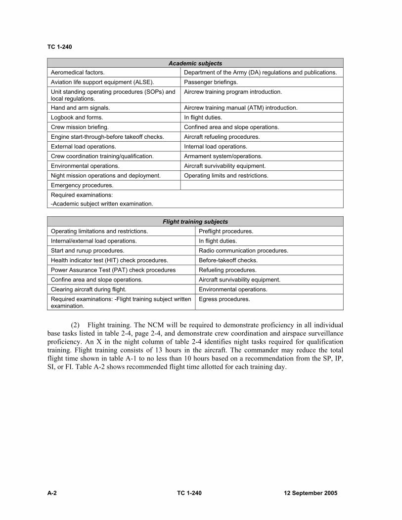
TC 1-240
A-2 TC 1-240 12 September 2005
Academic subjects Aeromedical factors. Department of the Army (DA) regulations and publications. Aviation life support equipment (ALSE). Passenger briefings. Unit standing operating procedures (SOPs) and local regulations.
Aircrew training program introduction.
Hand and arm signals. Aircrew training manual (ATM) introduction. Logbook and forms. In flight duties. Crew mission briefing. Confined area and slope operations. Engine start-through-before takeoff checks. Aircraft refueling procedures. External load operations. Internal load operations. Crew coordination training/qualification. Armament system/operations. Environmental operations. Aircraft survivability equipment. Night mission operations and deployment. Operating limits and restrictions. Emergency procedures. Required examinations: -Academic subject written examination.
Flight training subjects
Operating limitations and restrictions. Preflight procedures. Internal/external load operations. In flight duties. Start and runup procedures. Radio communication procedures. Health indicator test (HIT) check procedures. Before-takeoff checks. Power Assurance Test (PAT) check procedures Refueling procedures. Confine area and slope operations. Aircraft survivability equipment. Clearing aircraft during flight. Environmental operations. Required examinations: -Flight training subject written examination.
Egress procedures.
(2) Flight training. The NCM will be required to demonstrate proficiency in all individual
base tasks listed in table 2-4, page 2-4, and demonstrate crew coordination and airspace surveillance proficiency. An X in the night column of table 2-4 identifies night tasks required for qualification training. Flight training consists of 13 hours in the aircraft. The commander may reduce the total flight time shown in table A-1 to no less than 10 hours based on a recommendation from the SP, IP, SI, or FI. Table A-2 shows recommended flight time allotted for each training day.

Nonrated Crewmember and Nonrated Trainer Training and Qualification
12 September 2005 TC 1-240 A-3
Table A-1. Flight training for nonrated crewmembers
Flight Instruction Flying Hours
Base tasks1 9.0 Emergency procedures2 2.0 Evaluation3 2.0 Total hours 13.0 Notes: 1—A minimum of one hour will be at night. 2—Emergency procedures are required in each mode of flight. 3—The evaluation may be a continual evaluation.
Table A-2. Recommended flight training sequence
Flight Training Sequence Training day 1 2 3 4* 5 Daily 2.5 2.5 2.5 2.5 3.0E
Cumulative time 2.5 5.0 7.5 10 13.0 Note: The * denotes night flight and E denotes evaluation. All measurements are in hours.
(3) Documentation. Upon completion of training, an entry will be made in the remarks
section of DA Form 7122-R of the NCM’s IATF. At the NCM’s next closeout, training will be documented on the crewmember’s DA Form 759 (Individual Flight and Flight Certificate–Army), part V, remarks section. A separate entry in the closeout is required for completion of aircraft qualification training.
b. Night vision goggles qualification. NVG qualification will be accomplished per paragraph 2-1b, page 2-1.
c. Refresher training. Refresher training will be accomplished per paragraph 2-2, page 2-2.
d. Mission training. Mission training will be accomplished per paragraph 2-3, page 2-5.
e. Continuation training. Continuation training will be accomplished per paragraph 2-4, page 2-7.
f. Nuclear, biological, and chemical training. NBC training will be accomplished per paragraph 2-7, page 2-13.

TC 1-240
A-4 TC 1-240 12 September 2005
A-2. STANDARDIZATION INSTRUCTOR, FLIGHT ENGINEER INSTRUCTOR, AND NONRATED CREWMEMBER UNIT TRAINER TRAINING AND QUALIFICATION.
a. Qualification training. (1) SI/FI training/qualification.
(a) Prerequisites for FI qualification. 15U NCM in the rank of SGT through SSG with a minimum of 1-year experience as a CH-47 flight engineer (FE), possess a current flight physical, and be on crewmember orders.
(b) Initial FI training. This training is conducted at USAAVNC, Ft. Rucker, AL. An SP, IP, or SI will conduct initial validation of a crewmember’s qualification following this course of instruction and at each new duty station in the aircraft. Additional academic and flight hour requirements are at the discretion of the unit commander.
(c) SI qualification. An SI must be an FI and it is recommended that the SI have a minimum of 1-year experience as a CH-47 FI. The SI must be able to supervise and implement the commander’s ATP for NCMs and assist the unit SP with the supervision and maintenance of the standardization program.
(d) Documentation. Upon completion of the SI/FI qualification training and evaluation, the SP/IP/SI/FI (as appropriate) will enter the evaluation results on the NCM’s IATF DA Form 7122. Upon completion of a satisfactory evaluation, the DA Form 7120-R will be changed to reflect the new flight duty position and obtain the commander’s approval (initial and date on the DA Form 7120-R). At the NCM’s next closeout, training will be documented on the crewmember’s DA Form 759, part V, remarks section.
(2) UT qualification training. The NCM UT was created to lessen the training burden on the FIs/SIs. The UT can instruct RL2/RL1 crewmembers on certain tasks for which they show an expert knowledge. It was not created to make additional FIs/SIs. Once designated as a UT, he may conduct FE duties or conduct training in the mission/additional tasks that he is designated to instruct. UTs will not conduct training on RL3 crewmembers, nor will they perform evaluations.
Note: The goal should not be to make all FEs into UTs in all mission/additional tasks, but rather to give the FEs the ability to instruct tasks in which they are subject matter experts.
(a) Prerequisites for UT qualification. The unit commander is responsible for conducting UT qualification in accordance with this ATM. Recommended Active Army, National Guard, and Reserve component personnel in grade of SPC through SSG, must be a current CH-47 RL1 FE, possess a current flight physical, and be on crewmember orders.
(b) Academic training. Academic training will be conducted at the unit level. The NCM must receive sufficient instruction to demonstrate proper method of instruction (MOI) and be knowledgeable in the mission/additional task(s) he is designated to instruct. He must be able to effectively impart that knowledge to an RL2 crewmember.
(c) Flight training. The UT will be evaluated on his ability to perform, train, and provide method of instruction (MOI) for the specific mission/additional tasks in which he is designated to instruct. He will be required to demonstrate MOI proficiency in designated task(s) and must be able to instruct crew coordination and airspace surveillance in those tasks. All flight tasks will be performed to proficiency.
(d) Documentation. Upon completion of the UT qualification training and evaluation, the SP/IP/SI/FI (as appropriate) will enter the evaluation results on the NCM’s IATF DA Form 7122. Upon completion of a satisfactory evaluation, the DA Form 7120-R will be changed to reflect the new flight duty position and obtain the commander’s approval (initial and date on the DA Form 7120-R). At the NCM’s next closeout, training will be documented on the crewmember’s DA Form 759, part V, remarks section.

12 September 2005 TC 1-240 B-1
Appendix B
Heads-Up Display
B-1. GENERAL. HUD qualification will be conducted in accordance with this ATM or applicable POI. HUD qualified UTs, IPs, or SPs will conduct academic training and flight training. A HUD-qualified IP or SP will conduct the flight evaluations; qualification must be completed within 90 days.
B-2. QUALIFICATION TRAINING. Qualification training will provide the aviators with the knowledge, skills, and techniques required to integrate HUD operations into NVG flight. Training in the aircraft will be with the aviator at a station with access to the flight controls, wearing ANVIS with HUD attached. A HUD qualified IP, SP, or UT will be at the other station with access to the flight controls. HUD qualification training may be conducted concurrently during NVG qualification, refresher, and mission training.
Note: Academic training and training flights may be conducted by an NVG UT designated by the commander to conduct HUD training. When flight training is conducted by a UT, the trainee must be designated at least NVG RL2. A HUD-qualified NVG IP/SP must conduct the evaluation.
Note: Once qualified, the RCM has no currency requirements for HUD operations unless specified by the commander. One RCM may fly with the HUD and the other without. There is no requirement for both RCMs to fly with the HUD, unless specified by the commander. Academic training must be completed before flight training begins.
B-3. ACADEMIC TRAINING. Using the NVG TSP that incorporates HUD academic training or the HUD computer based trainer, the trainee will receive instruction in the following subject areas:
a. AN/AVS-7 HUD system components.
b. HUD symbology.
c. HUD system operations (programming, adjusting, and operating).
B-4. FLIGHT TRAINING. This program outlines the minimum flight hour requirements for HUD qualification. Some RCMs may require additional flight periods to achieve a satisfactory level of proficiency with the ANVIS HUD. Because initial HUD training can cause the aviator to be distracted, NCM should be stationed on the same side of the aircraft as the trainee. HUD training requires the RCM to develop new scanning habits. Time must be allowed to absorb this new information and develop new scan patterns; therefore, training days will not be combined. Each training day involving aircraft flights will be completed sequentially on separate nights.
Note: Training day 1 includes 1.0 hour of static aircraft HUD training concentrating on programming. The 1.0 hour of static aircraft training in programming and operations must be completed before the first flight. Training days 1 and 2 may be completed in the aircraft or synthetic flight training system (SFTS). Hours indicated in table B-1 denote the minimum hours per flight training period. Flight training periods will not be reduced. The program in table B-1 gives the minimum required flight training for qualification.

TC 1-240
B-2 TC 1-240 12 September 2005
Table B-1. Heads-up display training program
Training Day 1 2 3 4
Aircraft (hours) 1.0 1.0 1.0
Static training (hours) 1.0
Cumulative hours 1.0 2.0 3.0 4.0
B-5. TRAINING DOCUMENTATION. After crewmembers complete AN/AVS-7 initial qualification, units will ensure that an entry is made on the crewmember's DA Form 7122-R and transcribed to the DA Form 759.

12 September 2005 TC 1-240 C-1
Appendix C
T55-L-712 and T55-GA-714 Qualification Training
C-1. T55-L-712 QUALIFICATION TRAINING.
a. General. T55-L-712 qualifications will be conducted locally in accordance with the operator’s manual, this ATM, or the equipment manufacturer’s instructions, as appropriate. Upon completion of training, an entry will be made on DA Form 7122-R. At the aviator’s next closeout, the qualification will be documented on the crewmember’s DA Form 759, part V, remarks section.
b. Prerequisites. (1) SOP. A unit SOP is not required for this training. (2) Previous qualifications.
(a) RCMs must be rated in CH-47 aircraft equipped with T55-GA-714. (b) NCMs must be qualified as a 15U crewmember.
(3) Conditions. No special conditions are specified for this training. (4) Personnel requirements. Personnel assigned to units equipped with aircraft fitted with
T55-L-712 engines must be qualified in accordance with this appendix. (5) Equipment requirements. Aircraft modified with T55-L-712 engines and current
publications are required for this training. (6) RL. Crewmembers undergoing this training are RL3 until completion of the training if
the unit’s aircraft are equipped exclusively with T55-L-712 engines. If the unit has aircraft modified with both T55-GA-714 and T55-L-712 engines, the crewmember’s RL status will not change while training.
c. Academic training. (1) Training material. The following publications are required to conduct this training.
(a) TC 1-240, CH-47. (b) TM 1-1520-240-10. (c) TM 1-1520-240-CL. (d) TM 1-1520-240-PMD. (e) TM 1-1520-240-MTF. (f) TM 1-1520-240-PM. (g) TM 1-1520-240-23 series. (h) TM 1-1520-240-23P series.
(2) Authorized academic trainers. All trainers must be T55-L-712-qualified before conducting training. Authorized trainers are any: SP, IP, ME, SI, or FI and can train any: CE, FE, FI, SI, UT, PI, PC, IP, and SP.
(3) Academic content. As a minimum, the training should cover the following topics. (a) Comprehensive publication overview. (b) T55-GA-714 and T55-L-712 general characteristics and differences. (c) Associated limitations and emergency procedures.
(4) T55-L-712 specific maintenance task for CEs, FEs, FIs, and SIs. Note: Academic training must be completed before the start of flight training.

TC 1-240
C-2 TC 1-240 12 September 2005
d. Flight training. (1) Minimum hours. The minimum hours for qualification are as follows:
(a) PI and PC—1.5 hours (two separate flights, the first flight in the right seat and the second flight in the left seat).
(b) CE, FE, FI, and SI—1.5 hours. (c) IP and SP—1.0 hour in addition to C-3a(1) (this flight will concentrate on
emergency procedure training). (d) MP and ME—NA.
Note: Flight time in the aircraft may be reduced by 50 percent with the use of a CH-47D FS with T55-L-712 incorporated simulation.
(2) Minimum tasks. The minimum tasks for qualification training are as follows: (a) PI, PC, IP, and SP tasks.
Prepare PPC. Perform preflight inspection. Perform before-starting engine through before-leaving helicopter checks. HIT. Perform hover power check. Perform emergency procedures.
(b) CE, FE, FI, and SI tasks. Perform preflight inspection. Perform before-starting engine through before-leaving helicopter checks. Perform emergency procedures. HIT.
(c) MP and ME tasks. Incorporated in the USAAVNC CH-47 MTPC. (3) Authorized trainers.
(a) SI/FI can train CE, FE, FI, and SI. (b) SP/ IP can train CE, FE, FI, SI, PI, PC, IP, and SP.
(c) ME NA.
e. Evaluations. (1) Qualification. End of training evaluation or a continuous evaluation. (2) Annual. No annual evaluation is required. (3) Currency. No currency evaluation is required. (4) Authorized evaluators.
(a) FI can evaluate CE or FE. (b) SI can evaluate CE, FE, FI, and SI. (c) IP can evaluate CE, FE, FI, SI, PI, and PC (d) SP can evaluate CE, FE, FI, SI, PI, PC, IP, and SP. (e) ME can evaluate MP and ME.
C-2. T55-GA-714 QUALIFICATION TRAINING.
a. General. T55-GA-714 qualifications will be conducted locally in accordance with the initial system training (IST), the airworthiness release (AWR), the interim statement of airworthiness qualification, the TSP, the operator’s manual, this ATM, or the equipment manufacturer’s instructions, as appropriate. On completion of training, an entry will be made on DA Form 7122-R.

T55-L-712 and T55-GA-714 Qualification Training
12 September 2005 TC 1-240 C-3
At the aviator’s next closeout, the qualification will be documented on the crewmember’s DA Form 759, part V, remarks section.
b. Prerequisites.
(1) SOP. A unit SOP is not required for this training. (2) Previous qualifications.
(a) RCMs must be rated in CH-47 aircraft equipped with T55-L-712 engines. (b) NCMs must be qualified as a 15U crewmember.
(3) Conditions. No special conditions are specified for this training. (4) Personnel requirements. Personnel assigned to units equipped with aircraft fitted with
T55-GA-714 engines must be qualified in accordance with this appendix. (5) Equipment requirements. Aircraft modified with T55-GA-714 engines, electronic
torque-meter flight line test set, soldier’s portable on-system repair tool (SPORT) computer, and current publications are required for this training.
(6) RL. Crewmembers undergoing this training are RL3 until completion of the training if the unit’s aircraft are equipped exclusively with T55-GA-714 engines. If the unit has aircraft modified with both T55-L-712 and T55-GA-714 engines, the crewmember’s RL status will not change while training.
c. Academic training.
(1) Training material. The following publications are required to conduct this training. (a) Eastern Army National Guard (ARNG) aviation training site (EAATS)
T55-GA-714 initial system training manual (13 DEC 99 version 2.0 or later) or the most current version available on compact disk (CD) for CBT.
(b) TC 1-240, CH-47. (c) TM 1-1520-240-10. (d) TM 1-1520-240-CL. (e) TM 1-1520-240-PMD. (f) TM 1-1520-240-MTF. (g) TM 1-1520-240-PM. (h) TM 1-1520-240-23 series. (i) TM 1-1520-240-23P series.
(2) Authorized trainers. All trainers must be T55-GA-714-qualified before conducting training.
(a) NCM UT/FI/SI can train CE, FE, NCM UT, FI, and SI. (b) RCM UT/IP/SP/ME can train CE, FE, FI, SI, UT, PI, PC, IP, SP, MP, and ME.
(3) Academic content. As a minimum, the training should cover the following topics: (a) Comprehensive publication overview. (b) T55-L-712 and T55-GA-714 general characteristics and differences. (c) FADEC description and components. (d) Associated limitations and emergency procedures. (e) T55-GA-714 specific maintenance task for CEs, FEs, FIs, SIs, MPs, and MEs.
Note: Academic training must be completed before the start of flight training.
d. Flight training. (1) Minimum hours. The minimum hours for qualification are as follows:
TC 1-240
C-4 TC 1-240 12 September 2005
(a) PI and PC—1.5 hours (two separate flights, the first flight in the right seat and the second flight in the left seat).
(b) CE, FE, FI and SI—1.5 hours. (c) IP and SP—1.0 hour in addition to C-2 d(1) (third flight concentrating on
emergency procedure training). (d) MP and ME—1.0 hour in addition to C-2 d(1) (third flight concentrating on
maintenance test flight tasks in the left seat conducted by an ME). (2) Minimum tasks. The minimum tasks for qualification training are as follows:
(a) PI, PC, IP, and SP tasks— Prepare PPC. Perform preflight inspection. Perform before-starting engine through before-leaving helicopter checks. Perform PAT check. Perform hover power check. Perform emergency procedures.
(b) CE, FE, FI and SI tasks— Perform preflight inspection. Perform before-starting engine through before-leaving helicopter checks. Perform PAT check. Perform emergency procedures.
(c) MP and ME tasks— Same tasks in PI, PC, IP and SP, 2(a) above and the following tasks. Perform starting engine checks (714). Perform electrical system checks. Perform PAC (714). Perform droop eliminator check. Perform self-tuning vibration absorber check. Perform RRPM droop check and thrust rod slippage check. Perform auto-rotational RPM check. Perform power assurance test. Perform DECU start bit check. Perform FADEC system check. Perform P3 bellows check. Perform PTIT load share check. Perform torque differential check. Develop a trigger value.
(3) Authorized trainers.
(a) FI/SI can train CE, FE, FI, and SI. (b) IP/SP can train CE, FE, FI, SI, PI, PC, IP, and SP. (c) ME can train MP and ME. (The MP or ME candidate must be T55-GA-714-
qualified as a PI or PC before receiving maintenance tasks training from the ME.)
e. Evaluations. (1) Qualification. End of training evaluation or a continuous evaluation.

T55-L-712 and T55-GA-714 Qualification Training
12 September 2005 TC 1-240 C-5
(2) Annual. No annual evaluation is required. (3) Currency. No currency evaluation is required. (4) Authorized evaluators—
(a) FI can evaluate CE or FE. (b) SI can evaluate CE, FE, FI, and SI. (c) IP can evaluate CE, FE, FI, SI, PI, and PC (d) SP can evaluate CE, FE, FI, SI, PI, PC, IP, and SP. (e) ME can evaluate MP and ME.
Note: T55-GA-714A qualifications training for crewmembers previously qualified in the T55-L-714 engine consist of academic training concentrating on engine differences. There is no flight-training requirement for T55-GA-714A qualification if previously T55-L-714-qualified. Once the academic training is complete, the qualification will be documented on the DA Form 7122-R and the DA Form 759, remarks section, as previously stated.

This page intentionally left blank.
12 September 2005 TC 1-240 D-1
Appendix D
Instructor Pilot Supplemental Information
D-1. EMERGENCY PROCEDURES TRAINING.
a. Emergency procedures. The following procedures will only be performed in the aircraft in an actual emergency:
(1) Touchdown autorotation. (2) Running landing to water. (3) Single-engine takeoff from the ground. (4) Actual engine stoppage in flight or during taxi. (5) Power transfer unit switches ON or No. 1 or No. 2 hydraulic control switches out of the
BOTH position during taxiing or flight. (6) Both engine condition levers out of the flight position during taxiing or flight. (7) Bus-tie relay disabled or gang bar placed down. (8) APU operations during taxiing or flight. (9) Jettison of external load. (10) Emergency descent. (11) Dual full authority digital electronic control (FADEC) primary and/or reversionary
failure (may be performed by DES-trained SP, IP, or ME at USAAVNC and other DA-approved training sites and by DES-trained instructors during individual 714 qualifications).
(12) ECL out of flight position with other engine FADEC switch in reversionary. (13) Engine shutdown with APU inoperative. (14) Dual generator failure. (15) Dual rectifier failure. (16) AFCS-OFF external load hook-up.
b. Additional emergency procedures. In addition to the emergency procedures listed in paragraph D-2 below, SPs/IPs may also demonstrate:
(1) Cargo hook manual release. (2) Cargo hook pneumatic release, if the pre-charge is low and requires servicing.
c. The emergency procedures listed herein are demonstrated, practiced, and evaluated during training. Any emergency procedure may be simulated and the procedure performed in the CH-47FS. The performance of simulated emergency procedure training in the aircraft will be briefed prior to the flight and all emergencies will be considered actual unless stated otherwise. Aircraft emergency conditions, procedures, restrictions, and the only authorized methods of simulating the condition in the aircraft are outlined in paragraph D-2.
TC 1-240
D-2 TC 1-240 12 September 2005
WARNING
Simulation of emergency conditions, other than verbal, in the actual aircraft will only be accomplished while the aircraft is operating in visual meteorological conditions (VMC).
D-2. INSTRUCTOR PILOT TECHNIQUES.
a. Autorotate. (1) Conditions. May only be performed in the CH-47FS. (2) Simulation. NA
b. Emergency engine shutdown. (1) Condition. Initiated with the ECL in the ground detent and met the required engine cool
down. (2) Simulation. A verbal description of the procedure should accompany the single-engine
failure emergency procedure (time permitting). May not be performed during taxi or flight, except in the CH-47FS.
c. Abort start. (1) Conditions. Initiated during the engine start sequence or when the aircraft is parked,
brakes set, ECL in the ground detent, and the required engine cool down met. (2) Simulation. Verbally direct the crewmember to abort the start, or initiate at the
instructor operator station (IOS) of the CH-47FS. May also utilize the FE/CE to verbally state conditions requiring the engine start be aborted.
d. Dual-engine failure. (1) Conditions. May only be performed in the CH-47FS. (2) Simulation. Initiate at IOS of the CH-47FS.
e. Single-engine failure—low altitude/low airspeed and cruise. (1) Low altitude/low airspeed.
(a) Conditions. Performed when single-engine hover OGE capability exists. This condition may be simulated during external load operations in the aircraft if the cargo hook master switch is OFF to prevent inadvertent load jettison. IP should be especially vigilant and ready to use emergency release, as required when the master switch is off.
(b) Simulation. 712—Using ECL or emergency engine trim switches to decrease N1 to ground
idle. 714—Using the ECL, decrease the N1 to ground idle. The crewmember should
state the indications and the IP announces engine failure, illumination of the appropriate engine fail light, or states the N1 is simulated below 48 percent.
Note: An associated ENG FAIL caution is associated with an actual engine failure.
Instructor Pilot Supplemental Information
12 September 2005 TC 1-240 D-3
(2) Abort takeoff. (a) Conditions. Performed anytime the aircraft is operating in a position over a
suitable landing area to abort or operating above minimum single-engine airspeed and 100 feet AGL in a position to continue the single-engine takeoff. This emergency condition will not be simulated during external load operations unless single-engine hover OGE capability exists.
(b) Simulation. Same as e(1)(b) above. (3) Cruise.
(a) Conditions. Performed anytime the aircraft is above 200 feet AGL in a cruise profile. When conducting external load operations, the cargo hook master switch shall be OFF.
(b) Simulation: Same as e(1)(b) above. Note: When operating with only one engine online, that engine must remain in the primary FADEC mode of operation.
f. Engine restart during flight. (1) Conditions. May only be performed in the CH-47FS. (2) Simulation. After a single-engine failure, the crewmember should determine if it is
feasible to perform an engine restart.
g. Normal engine beep trim system failure (high side) or power turbine (speed) (N2) governor failure.
(1) Conditions. Anytime. If external load operations are performed, the cargo hook master switch will be OFF.
(2) Simulation. Increase the RRPM using the No. 1 normal beep trim switch. Do not increase the rotor speed above 106 percent.
h. Normal engine beep trim system failure (low side or static). (1) Conditions. Anytime. If external load operations are being performed, the cargo hook
master switch shall be OFF. (2) Simulation.
(a) Decrease the No. 1 normal beep trim switch then disable the normal engine trim or:
(b) Disable the No. 1 or No. 2 normal beep trim system and decrease the engine speed appropriately with the respective emergency engine trim switch.
Note: Disable normal trim by pulling the TRIM and timer circuit breaker (A-17) or by placing the emergency engine trim auto/manual switch to the MANUAL position.
i. FADEC (Full Authority Digital Electronic Control) 1 or FADEC (Full Authority Digital Electronic Control) 2 caution.
(1) Conditions. Anytime. (2) Simulation. Place the appropriate PRI/REV (primary/reversionary) switch to the REV
position. It is important to ensure torque indicators are matched and operating RRPM is obtained before placing the switch again to the PRI position.
Note: For training purposes, a FADEC system soft fault can be demonstrated by pulling the PRI CONT circuit breaker (A-7) on the appropriate power distribution panel (PDP). This will only be done when the aircraft is on the ground before engine start or at engine shutdown to demonstrate procedures for clearing soft faults. When operating with only one engine online, that engine must remain in the primary FADEC mode of operation.
TC 1-240
D-4 TC 1-240 12 September 2005
j. FADEC 1 and FADEC 2 cautions. (1) Conditions. May only be performed in the CH-47FS. (This emergency procedure can be
performed in the aircraft by a DES-trained SP, IP, or ME at USAAVNC, other DA-approved training sites and by DES-trained instructors. DES trained instructors may train other instructors who then may perform this task).
(2) Simulation. Verbally describe indications. Place both No 1 and No 2 PRI/REV switches to REV.
k. 714 REV 1/REV 2 cautions (with) FADEC cautions. (1) Conditions. May only be performed in the CH-47FS. (2) Simulation. Verbally describe the indications.
l. 714 REV 1/REV 2 cautions (without) FADEC cautions. (1) Conditions. May only be performed in the CH-47FS. (2) Simulation. Verbally describe the indications.
m. Torque measuring system malfunction. (1) Conditions.
(a) 712—anytime. (b) 714—may only be performed in the CH-47FS.
(2) Simulation. (a) 712—pull either (A-5) circuit breaker for associated power supply unit or (A-15)
circuit breaker for associated torque gauge. (b) 714—for training purposes a FADEC system soft fault can be demonstrated by
pulling the DC TORQUE circuit breaker (A-5) on the appropriate PDP. This will only be done when the aircraft is on the ground before engine start, or at engine shutdown to demonstrate procedures for clearing soft faults.
n. Engine transmission clutch failure to engage. (1) Conditions. Anytime. (2) Simulation. Verbally state the indications.
o. Engine shutdown—complete electrical failure. (1) Conditions. May only be performed in the CH-47FS. (2) Simulation. Verbally state the indications.
p. Engine shutdown—condition lever failure. (1) Conditions.
(a) 712—Performed during shutdown after engine has stabilized in ground for two minutes.
(b) 714—May only be performed in the CH-47FS. (2) Simulation.
(a) 712—Disable engine-condition lever by pulling COND CONT circuit breaker (A-8).
(b) 714—Verbally state the indications.

Instructor Pilot Supplemental Information
12 September 2005 TC 1-240 D-5
q. Engine shutdown—with auxiliary power unit (APU) or APU generator inoperative. (1) Conditions. May only be performed in the CH-47FS. (2) Simulation. Require the crewmember to shutdown the engines after an APU or APU
generator failure.
r. Engine oil-low quantity/high temperature/high of low pressure. (1) Conditions. Anytime. (2) Simulation. Verbally describe the indications or pull circuit breaker (A-14/19) to fail
the engine oil pressure gauge. Note: If failed using the circuit breaker after engine start, the engine oil pressure indication on the oil pressure gauge will remain static (freeze) at the indication present when the circuit breaker was pulled.
s. Engine chip detector caution. (1) Conditions. Anytime. (2) Simulation. Verbally describe the indications.
t. No. 1 or No. 2 ENG XMSN HOT caution. (1) Conditions. Anytime. (2) Simulation. Verbally describe the indications.
u. Transmission debris screen latches. (1) Conditions. Anytime. (2) Simulation. Verbally describe the indications.
v. XMSN OIL PRESS caution. (1) Conditions. Anytime. (2) Simulation. Verbally describe the indications.
w. XMSN Oil PRESS and XMSN AUX OIL PRESS or XMSN CHIP DET caution. (1) Conditions. Anytime. (2) Simulation. Verbally describe the indications.
x. XMSN AUX OIL PRESS caution. (1) Conditions: Anytime. (2) Simulation: Verbally describe the indications.
y. XMSN OIL HOT caution. (1) Conditions. Anytime. (2) Simulation. Verbally describe the indications.
z. Engine HOT START. (1) Conditions. Anytime. (2) Simulation. Verbally state the PTIT is rising/smoke and flames are visible from the tail
cone.
TC 1-240
D-6 TC 1-240 12 September 2005
aa. Residual fire during shutdown. (1) Conditions. Anytime. (2) Simulation. Verbally state the PTIT is rising/smoke and flames are visible from the tail
cone.
bb. Auxiliary power unit fire. (1) Conditions. During shutdown (daylight only) after a 2-minute cool down with the ECLs
in ground or before engine starting. (2) Simulation. Verbally state the indications.
cc. Engine or fuselage fire—flight. (1) Conditions. Anytime. (2) Simulation. Place the fire detector test switch to test or verbally announce a fire. (If
external load operations are being performed, the cargo hook master switch shall be OFF.)
dd. Engine compartment, fuselage, or electrical fire—ground. (1) Conditions. During shutdown after a 2-minute cool down with the engines in ground; or
during engine starting. (2) Simulation. Place the fire detector test switch to test or verbally announce a fire. (Do
not allow the crewmember to place the APU or battery switch OFF, as you will be unable to monitor PTITs, motor the engines, or communicate with the FE.)
ee. Electrical fire—flight. (1) Conditions. Anytime. (2) Simulation. Verbally state a fire.
ff. Smoke and fume elimination. (1) Conditions. During day VMC only. (2) Simulation. State the presence of smoke and fumes in the cockpit.
gg. Auxiliary fuel pump failure. (1) Conditions. Anytime fuel is remaining in the auxiliary tanks. (2) Simulation. Pull the auxiliary fuel pump direct current (DC) circuit breaker (A1/A4 or
C20/C21). (The crewmember should detect an unbalanced fuel consumption or he should note the AUX PRESS light illuminated with fuel remaining in the tank.)
Note: The right AUX FUEL PUMP circuit breakers (A1 or A4) provide the power source for the left AUX PRESS light. If simulated during runup and before checking the fuel pumps, an inoperative left AUX PRESS light, as well as, an inoperative right aux pump will normally be present.
hh. Fuel venting. (1) Conditions. Anytime provided fuel is remaining in the aux tanks. (2) Simulation. Verbally state the indications.
ii. L or R FUEL PRESS caution. (1) Conditions. Anytime operating below 6,000 feet PA. (2) Simulation. Verbally state the indications or turn both fuel pump switches for a main
tank OFF or pull (A-2/B20) and (A-3/B21) circuit breakers.
Instructor Pilot Supplemental Information
12 September 2005 TC 1-240 D-7
jj. FUEL LOW caution. (1) Conditions. Anytime. (2) Simulation. Verbally state the indications.
kk. FUEL LOW and FUEL PRESS cautions. (1) Conditions. Anytime. (2) Simulation: Verbally state the indications.
ll. No. 1 or No. 2 GEN OFF caution. (1) Conditions. Anytime. (2) Simulation. Place either generator control switch to OFF.
Note: A bus-tie failure will only be simulated in the SFTS because of the loss of the associated AFCS, heater fan, hydraulic and avionics cooling fans, and the loss of power to vertical gyros. You may simulate the appearance of a single generator failure without a bus-tie by turning off the associated generator switch, AFCS, the main fuel pump switches, and by pulling XFMR RECT AC (B22) or REV CURR (C10/D7) circuit breakers.
mm. No. 1 and No. 2 GEN OFF cautions. (1) Conditions. Anytime. (2) Simulation. Verbally state the indications.
nn. No. 1 or No. 2 RECT OFF caution. (1) Conditions. Anytime. (2) Simulation. Pull either the XFMR RECT AC circuit breaker (B22) or the REV CUR
CO DC (C10/D7) circuit breaker. Note: To simulate a failure of the DC bus-tie relay in flight, the AFCS and fuel boost pumps for the affected side may be turned off.
oo. No. 1 and No. 2 RECT OFF cautions. (1) Conditions. Anytime. (2) Simulation. Verbally state the indications.
pp. BATT SYS MAL caution. (1) Conditions. Anytime. (2) Simulation. Verbally state the indications.
qq. No. 1 or No. 2 HYD FLT CONTR caution. (1) Conditions. Anytime. (2) Simulation. Verbally state the indications.
rr. No. 1 and No. 2 HYD FLT CONT cautions. (1) Conditions. Anytime. (2) Simulation. Verbally state the indications .
ss. UTIL HYD SYS caution. (1) Conditions. Anytime. (2) Simulation. Verbally state the indications.
TC 1-240
D-8 TC 1-240 12 September 2005
tt. Emergency descent. (1) Conditions. Will only be performed in the CH-47FS. (2) Simulation. Verbally state conditions requiring an emergency descent.
uu. Longitudinal cyclic trim system failure. (1) Conditions.
(a) Failure retracted. At airspeed less than VNE for LCT retracted. (b) Failure extended. At cruise airspeed, not below 70 KIAS.
(2) Simulation. Place the cyclic trim switch to MANUAL or pull the appropriate circuit breaker (B10/B9) for a failure of only one actuator. Observe airspeed operating limits.
vv. Single advanced flight control system failure—both selected. (1) Conditions. 100 KIAS or less. (2) Simulation. Place the AFCS Selector to either No. 1 or No.2 or pull the AFCS DC
circuit breaker (B13/B14). Observe airspeed operation limits.
ww. Dual advanced flight control system failure. (1) Conditions. 100 KIAS or less. (2) Simulation. Place the AFCS selector to OFF. Observe airspeed operating limits.
xx. Vertical gyro malfunction. (1) Conditions. VMC and 100 KIAS or less. (2) Simulation. Pull the pilot's or copilots VGI circuit breaker (B16/C15).
Note: If altitude hold is engaged and the copilot's VGI circuit breaker is pulled, a thrust CCDA runaway will occur.
yy. Differential airspeed hold failure. (1) Conditions. Anytime. (2) Simulation. Verbally describe the indications.
zz. Cockpit-control driver actuator failure. (1) Conditions. Anytime except during flight in turbulence. (2) Simulation.
(a) Pull the CLTV DRIVER ACTR (B12) on the No. 1 PDP (causes altitude hold feature to become inoperative and the thrust brake to remain released).
(b) Pull the THRUST BRAKE circuit breaker (D6) on the No. 1 PDP (causes the thrust brake to fail locked).

12 September 2005 TC 1-240 Glossary-1
Glossary
A AC Alernating Current
ACFT Aircraft ADF Automatic Direction Finding AFB Air Force Base
AFCS Advanced Flight Control Ssystem AFRM Assistant Fast-Rope Master
AGL Above Ground Level AHO Above Highest Obstacle AIM Aeronautical Information Manual
AL Alabama ALSE Aviation Aircrew Life Support Equipment AMC Air Mission Commander; Army Materiel Command
AMCOM U.S. Army Aviation and Missile Command AMMO Ammunition
ANCD Automated Net Control Device ANVIS Aviator’s Night Vision Imaging System
APART Annual Proficiency and ReadinessTest APU Auxiliary Power Unit
AR Army Regulation ARNG Army National Guard
ASE Aircraft Survivability Equipment ASET Aircraft Survivability Equipment Trainer
ASI Additional Skill Identifier ASR Airport Surveillance Radar ATC Air Traffic Control ATIS Automated Terminal Information Service ATM Aircrew Training Manual ATP Aircrew Training Program
ATTD Attitude ATTN Attention AUTO Automatic
AUX Auxiliary AVAIL Available
AVN Aviation
TC 1-240
Glossary-2 TC 1-240 12 September 2005
AWR Airworthiness Release B
BATT Battery BIT Built-in Test
BITE Built-in Test Equipment C C Celsius
CAL Caliber CAV Cavalry CBT Computer Based Training
CCDA Cockpit-Control Driver Actuator CD Compact Disk
CDI Course Deviation Indicator CE Crew Engineer (crew chief) CG Genter of Gravity
CGI Cruise Guide Indicator CH Cargo Helicopter
CH-47FS CargoHelicopter-47 Flight Simulator CHUM Chart Update Manual
CL Checklist CO Company
COMSEC Communication Security COMM Communication
CONT Continue CONUS Continental United States
CRRC Combat Rubber Raiding Craft CTL Commander’s Task List
D D Day; Demonstrated (for grade slip purposes)
DA Department of the Army DASH Differential Airspeed Hold
DC Direct Current; District of Columbia DECEL Deceleration
DECU Digital Engine Control Unit DES Directorate of Evaluation and Standardization
DGNS Doppler Global Positioning System Navigation System DH Decision Height
Glossary
12 September 2005 TC 1-240 Glossary-3
DOD Department of Defense DSN Defense Switched Network
E E3 Electromagnetic Environmental Effect
EAATS Eastern Army National Guard Aviation Training Site EAPS Engine Air Particle Separator
EAT External Air Transportability ECCM Electronic Counter-Countermeasures
ECL Engine Condition Lever ECM Electronic Countermeasures
EGI Embedded Global Positioning System Inertial Navigation System EMERG Emergency
ENG Engine EQUIP Equipment
ERFS Extended Range Fuel System ESU Electronic Sequencing Unit ETA Estimated Time of Arrival ETE Estimated Time Enroute ETL Effective Translational Lift ETP Exportable Training Package
F F Fahrenheit
FAA Federal Aviation Administration FAC Flight Activity Category
FADEC Full Authority Digital Electronic Control FAF Final Approach Fix FAR Federal Aviation Regulation
FARE Forward Area Refueling Equipment FARP Forward Arming and Refueling Point
FAT Free Air Temperature FE Flight Engineer FI Flight Engineer Instructor
FIH Flight Information Handbook FLIP Flight Information Publication FLT Flight FM Field Manual
FOD Foreign Object Damage
TC 1-240
Glossary-4 TC 1-240 12 September 2005
FPM Feet Per Minute FRIES Fast-Rope Insertion and Extraction
FRM Fast-Rope Master FW Fixed Wing
FWD Forward G
GA Georgia GND Ground GPS Global Positioning System GR Grade
GTF General Test Flight GWT Gross Weight
H HAATS High-Altitude Army Aviation Training Site
HHT Headquarters and Headquarters Troop HICHS Helicopter Internal Cargo Handling System HIRTA High Intensity Radio Transmission Area
HIT Health Indicator Test HQ Headquarters
HQDA Headquarters, Department of the Army HR Hour HSI Horizontal Situation Indicator
HUD Heads-Up Display HYD Hydraulic
I IAF Initial Approach Fix IAS Indicated Airspeed
IATF Individual Aircrew Training Folder ICAO International Civil Aviation Organization
ICS Internal Communications System ID Identification IE Instrument Examiner
IFF Identification, Friend or Foe IFR Instrument Flight Rules IGE In-Ground Effect ILS Instrument Landing System
IMC Instrument Meteorological Conditions

Glossary
12 September 2005 TC 1-240 Glossary-5
INCL Included IND Indicated IOS Instructor Operator Station
IP Instructor Pilot IR Infrared
IST Initial System Training ITO Instrument Takeoff
J JOG Joint Operations Graphic
K KIAS Knots Indicated Airspeed
KTAS Knots True Airspeed L
LAT Latitude LCT Longitudinal Cyclic Trim LOC Localizer
LONG Longitude LS Left Seat
LSE Landing Signal Enlisted LTF Limited Test Flight
LZ Landing Zone M
MAINT Maintenance MAP Missed Approach Point MAX Maximum
MCPC Maximum Continuous Power Check MDA Minimum Descent Altitude
MD Maryland ME Maintenance Test Flight Evaluator
MEF Maximum Elevation Figures MEM Memory
METL Mission Essential Task List METT-TC Mission, Enemy, Terrain and Weather, Troops and support
available, Time available, Civil considerations (the major factors considered during mission analysis)
MG Machine Gun MIJI Meaconing, Interference, Jamming, and Intrusion

TC 1-240
Glossary-6 TC 1-240 12 September 2005
MIN Minimum MM Millimeter MO Medical Officer
MOI Method Of Instruction MOPP Mission-Oriented Protective Posture
MOS Military Occupational Specialty MP Maintenance Test Pilot
MPC Maximum Power Check MSL Mean Sea Level MSN Mission MTF Maintenance Test Flight MTP Maintenance Test Pilot
MWO Maintenance Work Order N N Night
N1 Gas Producer (speed) N2 Power Turbine (speed) NA Not Applicable
NAS National Airspace System NATO North Atlantic Treaty Organization
NAVAID Navigation Aid NBC Nuclear, Biological, and Chemical
NCM Nonrated Crewmember NDB Nondirectional Beacon NGR National Guard Regulation
NM Nautical Mile NOE Nap-of-the-Earth
NOTAM Notice to Airmen NR Rotor (speed)
NSN National Stock Number NVD Night Vision Device NVG Night Vision Goggles NVS Night Vision System
O OAT Outside Air Temperature OGE Out-of-Ground Effect
OROCA Off Route Obstruction Clearance Altitude–CONUS

Glossary
12 September 2005 TC 1-240 Glossary-7
ORCTA Off Route Terrain Clearance Altitude–OCONUS P
P3 Pressure Third Stage P Pilot not on the controls
P* Pilot on the controls PA Pressure Altitude
PAC Power Assurance Check PAM Pamphlet PAR Precision Approach Radar PAT Power Assurance Test
PC Pilot In Command PDP Power Distribution Panel
PGRM Program PI Pilot (for grade slip purposes)
POI Program Of Instruction PM Preventive Maintenance
PMD Preventive Maintenance Daily POL Petroleum, Oil, Lubricants PPC Performance Planning Card PPH Pounds Per Hour PRI Primary
PROG Programmed PSI Pounds per Square Inch
PTIT Power Turbine Inlet Temperature PTU Power Transfer Unit
PZ Pickup Zone R
R/C Rate of Climb RCM Rated Crewmember
REPRO Reproducible RET Retract REV Reversionary
RL Readiness Level ROC Required Obstacle Clearance ROE Rules Of Engagement RPM Revolutions Per minute
RRPM Rotor Revolutions Per Minute

TC 1-240
Glossary-8 TC 1-240 12 September 2005
RS Right Seat RW Rotary Wing
S S Satisfactory (for grade slip purposes)
SALUTE Size, Activity, Location, Unit, Time, and Equipment SAM Surface-to-Air Missile SAR Search And Rescue SAT System Approach to Training
SE Single Engine SEL Select
SESC Single-Engine Service Ceiling SFTS Synthetic Flight Training System SGT Sergeant
SI Standardization Flight Engineer Instructor SM Statute Mile SOI Signal Operating Instructions SOP Standing Operating Procedure
SP Standardization Instructor Pilot SPC Specialist
SPORT Soldier’s Portable On-system Repair Tool SSG Staff Sergeant SSN Social Security Number
STANAG Standardization Agreement (NATO) STD Standard
STDA Self-Tuning Dynamic Absorber T
TACAN Tactical Air Navigation TAMMS-A The Army Maintenance Management System-Aviation
TAS True Airspeed TC Training Circular
TDH Time Distance Heading TEAC Turbine Engine Analysis Check
TERPS Terminal Instrument Procedures TM Technical Manual TQ Torque
TRADOC United States Army Training and Doctrine Command TSP Training Support Package

Glossary
12 September 2005 TC 1-240 Glossary-9
U U Unsatisfactory (for grade slip purposes)
UHF Ultra High Frequency U.S. United States USA United States Army
USAASA United States Army Aeronautical Services Agency USAASD-E United States Army Aeronautical Services Detachment-Europe USAAVNC United States Army Aviation Center
USAF United States Air Force UT Unit Trainer
V Vcgi Velocity Cruise Guide Indicator VFR Visual Flight Rules VGI Vertical Gyro Indicator VHF Very High Frequency
VMC Visual Meteorological Conditions Vne Velocity, (Airspeed) Never Exceed
VOR Very high frequency Omnidirectional Range VSI Vertical Speed Indicator
W Wt Weight Wx Weather
X XFEED Crossfeed XMSN Transmission
Z Z Zulu (Greenwich mean-time)

This page intentionally left blank.
12 September 2005 TC 1-240 References-1
References
SOURCES USED These are the sources quoted or paraphrased in this publication.
Army Publications and Forms
AR 95-27, Operational Procedures for Aircraft Carrying Hazardous Materials, 11 November 1994.
DA Form 759, Individual Flight Record and Flight Certificate—Army. FM 1-120, Army Air Traffic Services Contingency and Combat Zone Operations,
22 May 1995 (will be revised as FM 3-04.120). FM 2-0, Intelligence, 17 May 2004. FM 3-04.300, Flight Operations Procedures, 26 April 2004. FM 3-25.26, Map Reading and Land Navigation, 20 July 2001. FM 7-1, Battle Focused Training, 15 September 2003. FM 10-67-1, Concepts and Equipment of Petroleum Operations, 2 April 1998 (will be
revised as FM 4-20.12). FM 21-60, Visual Signals, 30 September 1987 (will be revised as FM 3-21.60). FM 24-35, Signal Operation Instructions “The SOI”, 26 October 1990. FM 44-80, Visual Aircraft Recognition, 30 September 1996 (will be revised as FM 3-01.80). TM 1-1500-328-23, Aeronautical Equipment Maintenance Management Policies and
Procedures, 30 July 1999. TM 9-1005-224-10, Operator’s Manual for Machine Gun, 7-62-MM, M60 W/E
(NSN 1005-00-605-7710 (EIC: 4AJ) and Machine Gun, 7.62-MM, M60 W/E (NSN 1005-00-909-3002) (EIC: 4A8) {TO 11W2-6-3-11}, 2 April 1998.
TM 9-1005-262-13, Operators, Aviation Unit and Aviation Intermediate Maintenance Manual for Armament Subsystem, Helicopter, 7.62-MM Machine Gun Mounts: Door Mounted, Lightweight, Model M23 P/N 11691604 (NSN 1005-00-907-0720); Door Mounted, Lightweight, Model M24 P/N 11691606 (NSN 1005-00-763-1404); Ramp Mounted, Lightweight, Model M41 P/N 8436598 (NSN 1005-00-087-2046), and Window Mounted, Lightweight, Model M144 P/N 12011812 (NSN 1005-01-193-4878), 29 December 1986.
TM 11-5810-262-10, Operator’s Manual for Speech Security Equipment KY-58 (NSN 5810-00-449-0154), 31 May 1990.
TM 11-5855-263-10, Operator’s Manual for Aviator’s Night Vision Imaging System (ANVIS) AN/AVS-6(V)1 (NSN 5855-01-138-4749) (EIC:IPR) AN/AVS-6(V)2 (NSN 5855-01-138-4748) (EIC:IPQ) AN/AVS-6(V)1A (NSN 5855-01-439-1745) (EIC:IPW) {To 12S10-2AVS6-1}, 1 February 2004.
TM 55-1500-342-23, Army Aviation Maintenance Engineering Manual for Weight and Balance, 29 August 1986.
TM 55-1520-240-23-1, Aviation Unit and Aviation Intermediate Maintenance Manual for CH-47D Helicopters, 10 September 2002.
TM 55-1520-240-23-2, Aviation Unit and Aviation Intermediate Maintenance Manual for CH-47D Helicopters, 10 September 2002.

TC 1-240
References-2 TC 1-240 12 September 2005
TM 55-1520-240-23-3, Aviation Unit and Aviation Intermediate Maintenance Manual for CH-47D Helicopters, 10 September 2002.
TM 55-1520-240-23-4, Aviation Unit and Aviation Intermediate Maintenance Manual for CH-47D Helicopters, 10 September 2002.
TM 55-1520-240-23-5, Aviation Unit and Aviation Intermediate Maintenance Manual for CH-47D Helicopters, 10 September 2002.
TM 55-1520-240-23-6, Aviation Unit and Aviation Intermediate Maintenance Manual for CH-47D Helicopters, 10 September 2002.
TM 55-1520-240-23-7, Aviation Unit and Aviation Intermediate Maintenance Manual for CH-47D Helicopters, 10 September 2002.
TM 55-1520-240-23-8, Aviation Unit and Aviation Intermediate Maintenance Manual for CH-47D Helicopters, 10 September 2002.
TM 55-1520-240-23-9, Aviation Unit and Aviation Intermediate Maintenance Manual for CH-47D Helicopters, 10 September 2002.
TM 55-1520-240-23-10, Aviation Unit and Aviation Intermediate Maintenance Manual for CH-47D Helicopter, 19 September 2002.
TM 55-1520-240-23-11, Aviation Unit and Aviation Intermediate Maintenance Manual for CH-47D Helicopter, 19 September 2002.
TM 55-1520-240-T-1, Aviation Unit and Aviation Intermediate Troubleshooting Manual for CH-47D Helicopter, 10 May 1983.
Department of Defense Publications
DD Form 365-4, Weight and Balance Clearance Form F-Transport/Tactical. DOD Aeronautical Information Manual (AIM) 86-100, Operation and Maintenance
Overview General Tri-service Mode 4 Handbook, May 1987. Flight Information Handbook. The DOD FLIP is available from Director, U.S. Army
Aeronautical Services Agency.
Standardization Agreement
STANAG 3114 (Edition Seven). Aeromedical Training of Flight Personnel. 22 May 2003.
DOCUMENTS NEEDED These documents must be available to the intended users of this publication.
*AR 40-8, Temporary Flying Restrictions Due to Exogenous Factors, 17 August 1976. AR 70-62, Airworthiness Qualification of US Army Aircraft Systems, 7 July 2000.
*AR 95-1, Aviation: Flight Regulations, 1 September 1997. *AR 95-2, Air Traffic Control, Airspace, Airfields, Flight Activities, and Navigational Aids,
10 August 1990. *AR 190-11, Physical Security of Arms, Ammunition and Explosives, 12 February 1998.
* This source was also used to develop this publication.

References
12 September 2005 TC 1-240 References-3
*AR 190-51, Security of Unclassified Army Property (Sensitive and Nonsensitive), 30 September 1993.
*AR 600-105, Aviation Service of Rated Army Officers, 15 December 1994. *AR 600-106, Flying Status for Nonrated Army Aviation Personnel, 8 December 1998. DA Form 2028, Recommended Changes to Publications and Blank Forms. DA Form 2408-12, Army Aviator’s Flight Record. DA Form 2408-13, Aircraft Status Information Record. DA Form 2408-13-1, Aircraft Maintenance and Inspection Record. DA Form 4186, Medical Recommendation for Flying Duty. DA Form 5484-R, Mission Schedule Brief. DA Form 5701-47-R, CH-47 Performance Planning Card. DA Form 7120-R, Commander’s Task List (LRA). DA Form 7122-R, Crewmember Training Record (LRA). DA Form 7382-R, Sling Load Inspection Record. *DA Pam 738-751, Functional Users Manual for the Army Maintenance Management
System-Aviation (TAMMS-A), 15 March 1999. DLAM 8210.1. Contractor’s Flight and Ground Operations. 13 November 2002. EM0250, TM 1-1680-377-13&P, Interactive Electronic Technical Manual for Air Warrior,
24 May 2004. *FM 1-112, Attack Helicopter Operations, 2 April 1997 (will be revised as FM 3-04.112). FM 1-113, Utility and Cargo Helicopter Operations, 12 September 1997 (will be revised as
FM 3-04.113). *FM 1-202, Environmental Flight, 23 February 1983 (will be revised as FM 3-04.202). *FM 1-203, Fundamentals of Flight, 3 October 1988 (will be revised as FM 3-04.203). *FM 1-230, Meteorology for Army Aviators, 30 September 1982 (will be revised as
FM 3-04.230). *FM 1-240, Instrument Flying and Navigation for Army Aviators, 15 December 1984 (will be
revised as FM 3-04.240). *FM 1-400, Aviator’s Handbook, 31 May 1983 (will be revised as FM 3-04.400). FM 3-04.111, Aviation Brigades, 21 August 2003.
*FM 3-04.140, Helicopter Gunnery, 14 July 2003. *FM 3.04-301 (FM 1-301), Aeromedical Training for Flight Personnel, 29 September 2000. FM 3-05.212, Special Forces Waterborne Operations, 31 August 2004. FM 3-21.38 (FM 57-38), Pathfinder Operations, 1 October 2002. FM 3-21.220, Static Line Parachuting Techniques and Tactics, 23 September 2003. FM 3-52 (FM 100-103), Army Airspace Command and Control in a Combat Zone,
1 August 2002. FM 3-100.2 (FM 100-103-1), ICAC2 Multiservice Procedures for Integrated Combat
Airspace Command and Control, 30 June 2000.
* This source was also used to develop this publication.
TC 1-240
References-4 TC 1-240 12 September 2005
FM 8-10-6, Medical Evacuation in a Theater of Operations Tactics, Techniques, and Procedures, 14 April 2000 (will be revised as FM 4-02.2).
*FM 55-450-2, Army Helicopter Internal Load Operations, 24 August 1984. *FM 10-450-3 (FM 55-450-1), Multiservice Helicopter Sling Load: Basic Operations and
Equipment, 10 April 1997 (will be revised as FM 4-20.197). *FM 10-450-4, Multiservice Helicopter Sling Load: Single Point Load Rigging Procedures,
30 May 1998. *FM 10-450-5, Multiservice Helicopter Sling Load: Dual-Point Rigging Procedures,
30 August 1999. FM 10-542, Airdrop of Supplies and Equipment: Rigging Loads for Special Operations,
7 October 1987. FM 20-11 (FM 20-11-1), Military Diving, 20 January 1999 (will be revised as FM 3-24.12). FM 20-32, Mine/Countermine Operations, 29 May 1998 (will be revised as FM 3-34.32). FM 31-19, Military Free-Fall Parachuting Tactics, Techniques, and Procedures,
1 October 1999 (will be revised as FM 3-05.211). FM 31-20-4, Special Reconnaissance Tactics, Techniques, and Procedures for Special
Forces, 23 March 1993 (will be revised as FM 3-05.203). FM 34-25-7, Special Electronic Mission Aircraft (SEMA) Survivability (U), 3 October 1995. FM 90-4, Air Assault Operations, 16 March 1987 (will be revised s FM 3-18.12).
*NGR (AR) 95-210, Army National Guard: General Provisions and Regulations for Aviation Training, 1 July 1991.
*TC 1-201, Tactical Flight Procedures, 20 January 1984. *TC 1-204, Night Flight Techniques and Procedures, 27 December 1988. *TC 1-210, Aircrew Training Program Commander’s Guide to Individual and Crew
Standardization, 3 October 1995. TM 5-4220-202-14, Maintenance Instructions with Parts Breakdown: USAF Floatation
Equipment, 1 April 1986. *TM 1-1520-240-10, Operator’s Manual for Army CH-47D Helicopter (EIC:RCD),
31 January 2003. *TM 1-1520-240-CL, Operator's and Crewmember's Checklist for Army CH-47D Helicopter,
31 January 2003. *TM 1-1520-240-MTF, Maintenance Test Flight Manual for Army Model CH-47D Helicopter,
31 January 2003. TM 1-1560-312-10, Operator’s Manual for Extended Range Fuel System II (ERFS II)
Configured for the Army CH-47 Helicopter P/N HM022-509 (NSN 1560-01-456-2704) (EIC: RCG), 30 September 2000.
* This source was also used to develop this publication.

References
12 September 2005 TC 1-240 References-5
TM 1-2840-248-23P, Aviation Unit and Intermediate Maintenance Repair Parts and Special Tools List (Including Depot Maintenance Repair Parts and Special Tools) for Engine Assembly, T700-GE-700, PN 6035TOOG01, (NSN 2840-01-070-1003), 31 March 1997.
TM 1-2840-265-23, Aviation Unit and Aviation Intermediate Maintenance Manual for Engine, Gas Turbine Model T55-GA-714A (NSN 2840-01-458-5361), 30 June 2000.
TM 11-1520-240-23, Aviation Unit and Aviation Intermediate Maintenance Manual for Army Model CH-47D Helicopter (NSN 1520-01-088-3669) (EIC: RCD) Avionics Configuration, 15 April 1996.
TM 11-1520-240-23P, Aviation Unit and Intermediate Maintenance Repair Parts and Special Tools List for CH-47D Electronic Equipment Configuration (NSN 1520-01-088-3669) (EIC: KTD), 1 June 2001.
TM 11-5855-300-10, Operator’s Manual for Heads Up Display AN/AVS-7 (NSN 5855-01-350-0349) (EIC: N/A), Heads Up Display AN/AVS-7(V)1 (5855-01-424-2284) (EIC: N/A), Heads Up Display AN/AVS-7(V)2 (5855-01-424-2285) (EIC: N/A), Heads Up Display AN/AVS-7(V)3 (EIC: N/A) (5855-01-42402286) (EIC: N/A), Heads Up Display AN/AVS-7(V)4 (5855-01-424-2287) (EIC: N/A), Heads Up Display AN/AVS-7(V)5 (5855-01-447-1071) (EIC: N/A), Heads Up Display AN/AVS-7(V)6 (5855-01-447-1887) (EIC: N/A), 1 December 1997.
*TM 11-5895-1199-12, Operator’s and Organizational Maintenance Manual for the Mark-XII IFF System, 1 July 1984.
TM 38-250, Preparing Hazardous Materials for Military Air Shipments, 11 December 2001. TM 55-1520-240-23, Aviation Unit and Aviation Intermediate Maintenance Manual for
CH-47D Helicopters, 19 September 2002. *TM 55-1520-240-PM, Phased Maintenance Checklist–CH-47D Helicopter, 25 May 2003. *TM 55-1520-240-PMD, Preventive Maintenance Daily Inspection Checklist–CH-47D
Helicopter, 25 May 2003. TM 55-1560-307-13&P, Operator, Aviation Unit and Aviation Intermediate Maintenance
Manual with Repair Parts and Special Tools List for Extended Range Fuel System Army Model CH-47 Helicopter Part Number 855DSCC-D-0007-2 (NSN 1560-01-221-7600), 11 December 1990.
TM 55-1680-317-23&P, Aviation Unit and Aviation Intermediate Maintenance Manual with Repair Parts and Special Tools List for Army Aircraft Survival Kits, 26 March 1987.
TM 55-1680-351-10, Operator’s Manual for SRU-21/P Army Vest, Survival (NSN 8465-00-177-4819) (Large), (8465-01-174-2355) (Small), 22 April 1987.
Nonmilitary Publications
Federal Aviation Regulation (FAR) Part 91, General Operating and Flight Rules, 4 November 2004.
FAR Part 105, Parachute Operations, 9 May 2001.
* This source was also used to develop this publication.

TC 1-240
References-6 TC 1-240 12 September 2005
These publications are available from Director, U.S. Army Aeronautical Services Agency. FAA-H-8083-15. Instrument Flying Handbook. FAA Order 7110.65. Air Traffic Control. 19 February 2004. FAA Order 7130.3. Holding Pattern Criteria. FAA Order 8460. Helicopter Global Positioning System Nonprecision Approach Criteria.
Joint Publications
JP 3-04.1, Joint Tactics, Techniques, and Procedures for Shipboard Helicopter Operations, 10 December 1997.
Other Requests for contractor flight releases, airworthiness releases, and/or interim or complete
airworthiness qualification for Army aircraft for which USAAMCOM has engineering cognizance will be forwarded to the Commander, USAAMCOM, ATTN: AMSAM-RD-AE-I, Redstone Arsenal, Alabama 35898-5000. Requests normally will come through the materiel developer (such as the program executive office or the system’s program/project/product manager) or from the field through a MACOM. Requests for airworthiness approval for major modifications installed on aircraft not under USAAMCOM engineering cognizance will be forwarded to the appropriate engineering cognizant agency (such as the Federal Aviation Administration, National Aeronautics and Space Administration, U.S. Air Force, or U.S. Navy). (See AR 70-62, paragraph 2-3.)
Standard Operating Instructions Equipment operator’s manual ASET programs Special Operations Command (SOCOM) Regulation 350-6 Army Aviator’s Handbook for Maneuvering Flight and Power Management Shipboard Aviation Facilities resume Aviation and Missile Command (AMCOM) Airworthiness Directives CH-47D Water Landing Airworthiness Release Water Bucket Airworthiness Release SPIES Airworthiness Release Ladder Airworthiness Release Helocast/Soft duck Airworthiness Release
READINGS RECOMMENDED These readings contain relevant supplemental information. AR 95-10, Department of Defense (DOD) Notice to Airmen (NOTAM) System,
1 January 1997. AR 385-95, Army Aviation Accident Prevention, 10 December 1999. FM 3-04.500, Army Aviation Maintenance, 26 May 2000. FM 3-3, Chemical and Biological Contamination Avoidance, 16 November 1992. FM 3-11.11, Flame, Riot Control Agency, and Herbicide Operations, 19 August 1996. FM 3-22.68, Crew-Served Machine Guns, 5.56-MM and 7.62-MM, 31 January 2003. FM 7-0, Training the Force, 22 October 2002.

References
12 September 2005 TC 1-240 References-7
FM 17-95, Cavalry Operations, 24 December 1996 (will be revised as FM 3-20.95). TM 1-2840-248-23, Aviation Unit and Intermediate Maintenance Manual for Engine,
Aircraft, Turboshaft, Model T700-GE-700, T700-GE-701 T700-GE-701C {To 2J-T700-6}, 1 June 1999.
TM 10-1670-201-23, Organizational and Direct Support Maintenance Manual for General Maintenance of Parachutes and Other Airdrop Equipment, 30 October 1973.
TM 11-5841-283-12, Aviation Unit Maintenance Manual for Radar Signal Detecting Set, AN/APR-39(V) (NSN 5841-01-023-7112), 9 August 1983.
TM 11-5855-238-10, Operator’s Manual for Night Vision Goggles Ground Use: AN/PVS-5 and AN/PVS-5A (NSN 5855-00-150-1820) (EIC:IPD) AN/PVS-5B (5855-01-228-0938) (EIC:IPV) AN/PVS-5C (5855-01-228-0936) (EIC:IPU) Aviation Use: GM-6(V)1 Goggles GM-6(V)2 Goggles, 15 May 1993.
TM 11-5865-263-12, Operator’s and Aviation Unit Maintenance (AVUM) Manual for Countermeasures Sets AN/ALQ-156(V)1, (V)2, (V3), (V)1 (NSN 5865-01-145-5197) (EIC: KDP) (V) 2 (NSN 5865-01-156-0460) (EIC: KD3) (V3) (NSN 5865-01-156-0459) (EIC: KD2), 1 September 1996.
TM 55-1520-240-T-2, Aviation Unit and Aviation Intermediate Troubleshooting Manual for CH-47D Helicopter, 10 May 1983.
TM 55-1520-240-T-3, Aviation Unit and Aviation Intermediate Troubleshooting Manual for CH-47D Helicopter, 10 May 1983.

This page intentionally left blank.

12 September 2005 TC 1-240 Index-1
Index
academic evaluation topics, 3-4 after-action reviews, 6-6 base tasks, 2-8 caution
meaning of, 1-1 checklist
after action review, 4-102 aircrew briefing, 4-7 crew briefing for external loads, 4-69 fast-rope operations, 4-135 nonrated crew briefing, 4-9
continuation training, 2-7 crew coordination. See chapter 6. crew terminology, 6-6 crewmember evaluation, 3-2
academic criteria, 3-3 performance criteria, 3-2
cross-monitoring, 6-5 currency requirements, 2-12 decisionmaking techniques, 6-3 engine peculiar tasks, 5-3 evaluation
debriefing, 3-7 evaluation principles, 3-1 evaluation sequence, 3-4 evaluators
selection of, 3-1 external loads
words and phrases, 4-70 flight evaluation, 3-7 grading considerations, 3-2 heads-up display. See appendix B. heads-up display (HUD) qualification, 2-6
instructor pilot training and techniques. See appendix D.
leadership, 6-2 mission tasks, 2-8 mission training, 2-5 note
meaning of, 1-1 nuclear, biological, and chemical training, 2-13 performance tasks, 2-8 personnel terminology, 1-2 premission planning, 6-2 qualification training, 2-1 refresher training, 2-2 situational awareness, 6-4 statements and directives, 6-4 symbol usage, 1-1 T55-L-712 and T55-GA-714 qualification training.
See appendix C. task conditions, 4-1 task description, 4-4 task list, 2-8 task standards, 4-3 technical tasks, 2-8 terminology
personnel, 1-2 unexpected events, 6-3 warning
meaning of, 1-1 word distinctions, 1-1 workload distribution, 6-3

This page intentionally left blank.
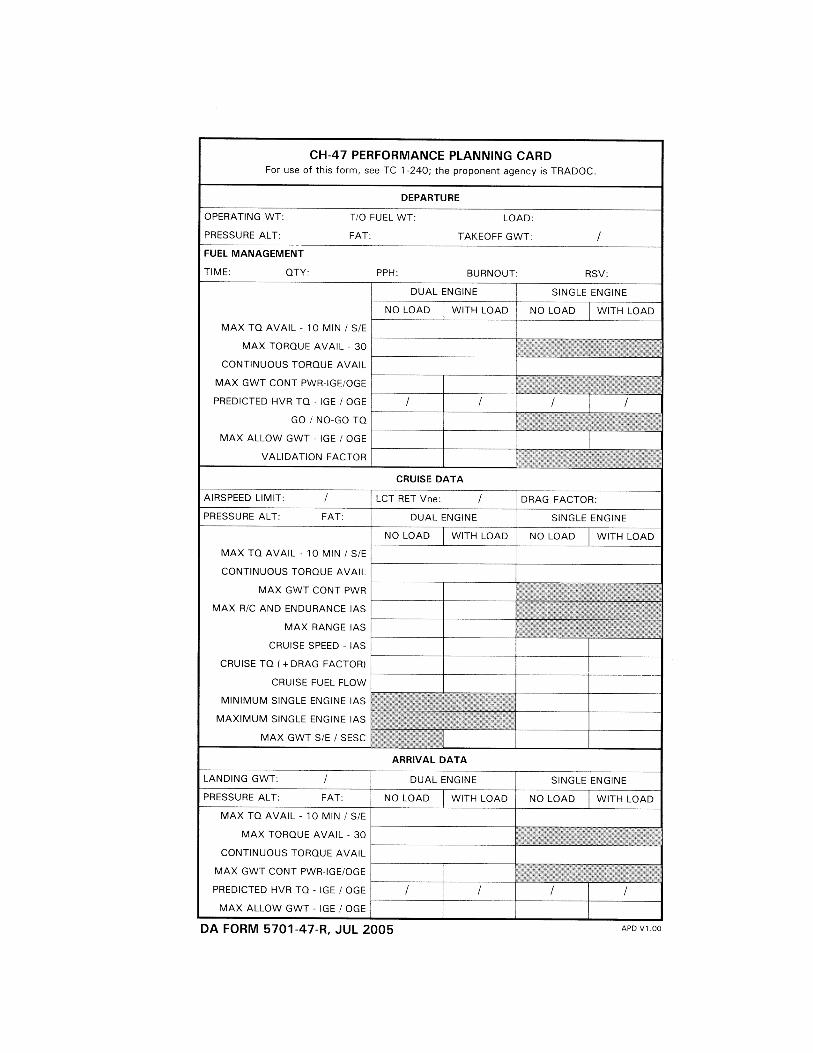

This page intentionally left blank.

TC 1-240 12 SEPTEMBER 2005
By order of the Secretary of the Army:
PETER J. SCHOOMAKER General, United States Army
Chief of Staff
Official:
SANDRA R. RILEY Administrative Assistant to the
Secretary of the Army 0523420
DISTRIBUTION: Active Army, Army National Guard, and U.S. Army Reserve: To be distributed in accordance with the initial distribution number (IDN) 113893 requirements for TC 1-240.

This page intentionally left blank.

This page intentionally left blank.

This page intentionally left blank.


PIN: 082696-000