airfield capacity and facility requirements
TRANSCRIPT
Chapter 4: Airfield Capacity and Facility Requirements 4-1
CHAPTER FOUR:
AIRFIELD CAPACITY AND FACILITY REQUIREMENTS 4.1 INTRODUCTION
A key step in the Airport Master Plan Update (AMPU) process is determining future requirements for airport facilities that will allow for airside and landside development over the term of the planning period. By comparing the existing conditions of an airport to its predicted growth patterns based upon both existing and future aircraft usage, an AMPU process can define requirements for runways, taxiways, aprons, hangars, terminals, and other related airport facilities to accommodate growth over the short-, intermediate-, and long-term planning periods. An essential step in the process of estimating future airport needs is the determination of an airport’s current capacity to accommodate anticipated demand. Such demand capacity analyses aid in the identification of airport deficiencies, surpluses, and opportunities for future development. Ultimately, they yield information that is used to design the Airport Layout Plan (ALP) and set the stage for future facility development. This chapter of the Belfast Municipal Airport (the Airport or BST) AMPU identifies facility requirements for the Airport through 2034. Existing and future facility requirements and development standards are identified based on current Airport strategic development initiatives and by comparing the Airport’s existing facilities to future facility needs based on forecasts of aviation demand presented in Chapter Three: Forecasts of Aviation Activity.
The Federal Aviation Administration (FAA) provides guidance for the planning and design of airport facilities through Advisory Circulars (ACs) that promote airport safety, economy, efficiency, and sustainability. Many of the facility requirements identified for BST incorporate FAA planning and design standards presented in AC 150/5300-13A, Airport Design. Other FAA ACs were used to develop sections of this chapter and are cited throughout the document. Chapter Five: Alternatives Analysis and Development Concepts of this AMPU examines alternatives for development based on the facility requirements and development standards identified for BST in this chapter.
Facility Requirements analysis establishes what airside and landside development should be planned for over the next 20 years.
AIRPORT MASTER PLAN UPDATE 2014
4-2 Chapter 4: Airfield Capacity and Facility Requirements
4.2 AIRFIELD DEMAND CAPACITY “Airfield Demand Capacity” refers to the number of aircraft operations that a given facility can accommodate on either an hourly or yearly basis. (Note that “capacity” does not relate to the size or weight of aircraft.) The capacity of an airfield is primarily a function of the major aircraft operating infrastructure elements that comprise an airfield (i.e., runways and taxiways), as well as their alignment and configuration. It is also related to and considered in conjunction with wind coverage, airspace utilization, and the availability and type of navigational aids. Each of these components has been examined as part of the airfield demand capacity analysis. Upon completion of the analysis of these various elements, a review of existing facilities has been provided and any additional requirements necessary to meet the forecasted demand have been identified in this chapter.
4.2.1 Capacity and Delay Airfield capacity is generally defined as the number of aircraft operations that can be safely accommodated on the runway-taxiway system at a given point in time before an unacceptable level of delay is experienced. The ability of the Airport’s current airside facilities to accommodate aviation operational demand is described below and is expressed in terms of potential excesses and deficiencies in capacity. The methodology used for the measurement of airfield capacity in this study is described in FAA AC 150/5060-5, Airport Capacity and Delay. Through this approach, airfield capacity is defined in the following terms:
Annual Service Volume (ASV): A reasonable estimate of an airport's annual capacity (i.e., level of annual aircraft operations that will result in an average annual aircraft delay of approximately one to four minutes).
Hourly capacity of runways: The maximum number of aircraft that can be accommodated under conditions of continuous demand during a one-hour period.
4.2.2 Airfield Operational Capacity Parameters and Assumptions Calculating airfield operational capacity is developed by the methods, parameters, and assumptions described in FAA AC 150/5060-5, Airport Capacity and Delay. The calculations are based on the runway utilizations that produce the highest sustainable capacity consistent with existing air traffic rules, practices, and guidelines. The parameters and assumptions utilized within this analysis and described below include the following:
Airfield layout (runway use configuration) Runway use Aircraft mix (based upon existing aircraft group demand) Percentage of arrival operations Touch-and-go operations Number and location of exit taxiways
Airfield capacity is defined as the theoretical number of aircraft operations that an airport can accommodate within a given period of time.
Delays that result from a deficiency in airfield capacity produce real losses with respect to time, money, and productivity.
Chapter 4: Airfield Capacity and Facility Requirements 4-3
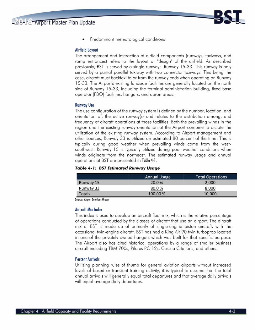
Predominant meteorological conditions Airfield Layout The arrangement and interaction of airfield components (runways, taxiways, and ramp entrances) refers to the layout or "design" of the airfield. As described previously, BST is served by a single runway: Runway 15-33. This runway is only served by a partial parallel taxiway with two connector taxiways. This being the case, aircraft must backtaxi to or from the runway ends when operating on Runway 15-33. The Airport's existing landside facilities are generally located on the north side of Runway 15-33, including the terminal administration building, fixed base operator (FBO) facilities, hangars, and apron areas. Runway Use The use configuration of the runway system is defined by the number, location, and orientation of, the active runway(s) and relates to the distribution among, and frequency of aircraft operations at those facilities. Both the prevailing winds in the region and the existing runway orientation at the Airport combine to dictate the utilization of the existing runway system. According to Airport management and other sources, Runway 33 is utilized an estimated 80 percent of the time. This is typically during good weather when prevailing winds come from the west-southwest. Runway 15 is typically utilized during poor weather conditions when winds originate from the northeast. The estimated runway usage and annual operations at BST are presented in Table 4-1.
Table 4-1: BST Estimated Runway Usage
Annual Usage Total Operations Runway 15 20.0 % 2,000 Runway 33 80.0 % 8,000 Totals 100.00 % 10,000
Source: Airport Solutions Group. Aircraft Mix Index This index is used to develop an aircraft fleet mix, which is the relative percentage of operations conducted by the classes of aircraft that use an airport. The aircraft mix at BST is made up of primarily of single-engine piston aircraft, with the occasional twin-engine aircraft. BST has had a King Air 90 twin turboprop located in one of the privately-owned hangars which was built for that specific purpose. The Airport also has cited historical operations by a range of smaller business aircraft including TBM 700s, Pilatus PC-12s, Cessna Citations, and others. Percent Arrivals Utilizing planning rules of thumb for general aviation airports without increased levels of based or transient training activity, it is typical to assume that the total annual arrivals will generally equal total departures and that average daily arrivals will equal average daily departures.
AIRPORT MASTER PLAN UPDATE 2014
4-4 Chapter 4: Airfield Capacity and Facility Requirements
Touch-and-Go Operations A touch-and-go operation refers to an aircraft maneuver in which the aircraft performs a normal landing followed by an immediate takeoff without stopping or taxiing clear of the runway. These operations are normally associated with flight training and are included in local operations figures. Given the current lack of a flight school based at the Airport, touch-and-go (local) operations have been assumed to comprise approximately 15 percent of the general aviation operations at BST (based on personnel estimates). This percentage of local touch-and-go operations is expected to remain relatively constant throughout the planning period. Taxiway Factors The capacity of a runway is greatly influenced by the ability of an aircraft to exit the runway as quickly and as safely as possible. Therefore, the quantity and design of the exit taxiways can directly influence aircraft runway occupancy time and the capacity of the runway system. The number and location of exit taxiways for Runway 15-33 at BST is inadequate for existing operations in that the existing taxiways are located near the midpoint of the runway. This requires aircraft departing the Airport to access Runway 15-33 midfield and then backtaxi to the departing runway end. Similarly, aircraft landing at BST will often decelerate beyond the taxiway exits, requiring them to backtaxi on the runway to access the terminal area. At the extreme case, the FAA requires pilots to conduct repeated full-stop operations regularly in order to maintain their ratings. In this situation, an aircraft at BST would be forced to backtaxi nearly the entire length of the runway for the pilot to land, stop, and then reposition the aircraft for another departure. Such backtaxi operations are highly discouraged by the FAA since they reduce the efficiency and operational capacity of a runway. But more importantly, they reduce that runway’s level of safety, since the longer an aircraft occupies an active runway, the greater the chance that there could be a conflict with another aircraft also operating at that runway. For these reasons, the current taxiway system at BST is considered to be inadequate. Runway Instrumentation The runway instrumentation included in the capacity calculations for BST include area navigation (RNAV) that includes Localizer Performance with Vertical Guidance approach capabilities, and non-directional beacon approach capabilities for Runway 15-33. Additionally, air traffic facilities, equipment, and services on the Airport and within the region are deemed to be adequate to carry out operations in a radar environment. Weather Influences Climatological conditions specific to the location of an airport not only influence the layout of the airfield, but also affect the use of the runway system. Surface wind conditions have a direct impact on airport operations in that runways not oriented to take the maximum advantage of prevailing winds will restrict the capacity of an airport to varying degrees. When landing and taking off, aircraft are able to
Chapter 4: Airfield Capacity and Facility Requirements 4-5
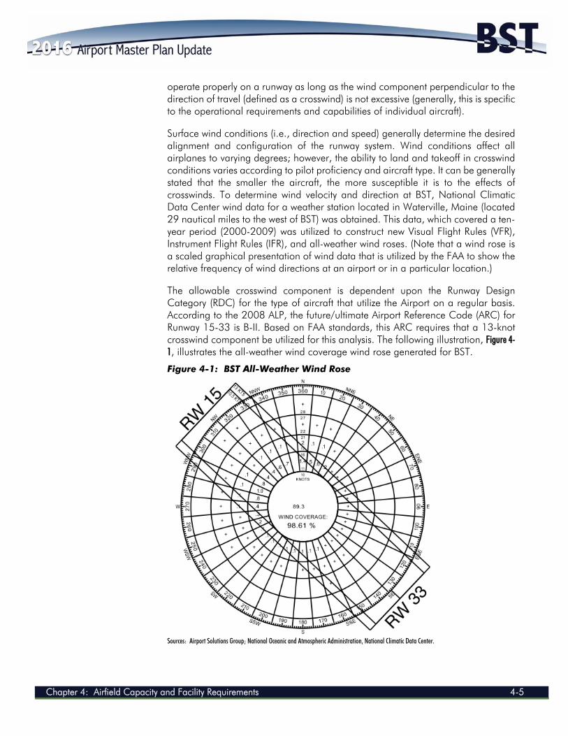
operate properly on a runway as long as the wind component perpendicular to the direction of travel (defined as a crosswind) is not excessive (generally, this is specific to the operational requirements and capabilities of individual aircraft). Surface wind conditions (i.e., direction and speed) generally determine the desired alignment and configuration of the runway system. Wind conditions affect all airplanes to varying degrees; however, the ability to land and takeoff in crosswind conditions varies according to pilot proficiency and aircraft type. It can be generally stated that the smaller the aircraft, the more susceptible it is to the effects of crosswinds. To determine wind velocity and direction at BST, National Climatic Data Center wind data for a weather station located in Waterville, Maine (located 29 nautical miles to the west of BST) was obtained. This data, which covered a ten-year period (2000-2009) was utilized to construct new Visual Flight Rules (VFR), Instrument Flight Rules (IFR), and all-weather wind roses. (Note that a wind rose is a scaled graphical presentation of wind data that is utilized by the FAA to show the relative frequency of wind directions at an airport or in a particular location.) The allowable crosswind component is dependent upon the Runway Design Category (RDC) for the type of aircraft that utilize the Airport on a regular basis. According to the 2008 ALP, the future/ultimate Airport Reference Code (ARC) for Runway 15-33 is B-II. Based on FAA standards, this ARC requires that a 13-knot crosswind component be utilized for this analysis. The following illustration, Figure 4-1, illustrates the all-weather wind coverage wind rose generated for BST.
Figure 4-1: BST All-Weather Wind Rose Sources: Airport Solutions Group; National Oceanic and Atmospheric Administration, National Climatic Data Center.
AIRPORT MASTER PLAN UPDATE 2014
4-6 Chapter 4: Airfield Capacity and Facility Requirements
The desirable wind coverage for an airport's runway system is 95 percent. This means that the runway orientation and configuration should be developed so that the maximum crosswind component is not exceeded more than five percent of the time annually. (Note that this is a recommendation, not a requirement.) Based on the all-weather wind analysis for the Airport and as reflected in Table 4-2, the existing runway configuration provides the following wind coverage: 98.61 percent for the 13-knot crosswind component (which is representative of larger multi-engine aircraft operating at BST), and 96.67 percent for the 10.5-knot crosswind component (which is representative of smaller single-engine aircraft operating at BST). Given that these results exceed the FAA recommendation of 95 percent, no additional runways are required at BST due to a lack of wind coverage.
Table 4-2: BST All-Weather Wind Coverage Summary
Wind Coverage Provided Under All‐Weather Conditions 10.5‐knot 13‐knot Runway 15 75.85 % 76.36 % Runway 33 92.34 % 94.13 % Runway 15‐33 96.67 % 98.61 %
Sources: Airport Solutions Group; National Oceanic and Atmospheric Administration, National Climatic Data Center, Station 72607. The Airport is served primarily by two non-precision approaches (an RNAV Global Positioning System with Localizer Performance with Vertical Guidance to both Runway 15 and Runway 33). To evaluate the effectiveness of these approaches, and analyze the potential benefits of implementing lower approach visibility minimums, an IFR wind rose has been constructed. Table 4-3 quantifies the wind coverage offered by each runway end in consideration of typical IFR conditions (ceiling less than 1,000 feet and/or visibility less than three standard or statute miles). Based on this IFR wind coverage summary, it can be concluded that Runway 15-33 provides adequate wind coverage for larger general aviation aircraft during IFR conditions and slightly less than the recommended 95 percent coverage for smaller aircraft. This means that there may be some occasions where BST does not provide adequate wind coverage for smaller aircraft during IFR conditions, forcing those aircraft to divert to another airport in the region. However, given the 92.06 percent coverage, this deficiency is not considered to be significant enough to warrant the construction of a new crosswind runway.
Table 4-3: BST Instrument Flight Rules Wind Coverage Summary
Wind Coverage Provided Under Instrument Flight Rules Weather Conditions 10.5‐knot 13‐knot Runway 15 83.39 % 84.88 % Runway 33 82.59 % 86.45 % Runway 15‐33 92.06 % 96.32 %
Sources: Airport Solutions Group; National Oceanic and Atmospheric Administration, National Climatic Data Center, Station 72607. Finally, Table 4-4 quantifies the wind coverage offered by each runway end in consideration of VFR conditions (ceiling greater than or equal to 1,000 feet and/or visibility greater than or equal to three statute miles). From this VFR wind coverage
Chapter 4: Airfield Capacity and Facility Requirements 4-7
summary, it can be determined that Runway 15-33 provides adequate (greater than 95 percent) wind coverage during VFR conditions.
Table 4-4: BST Visual Flight Rules Wind Coverage Summary
Wind Coverage Provided Under Visual Flight Rules Weather Conditions 10.5‐knot 13‐knot Runway 15 74.03 % 74.48 % Runway 33 93.03 % 94.66 % Runway 15‐33 97.06 % 98.83 %
Sources: Airport Solutions Group; National Oceanic and Atmospheric Administration, National Climatic Data Center, Station 72607.
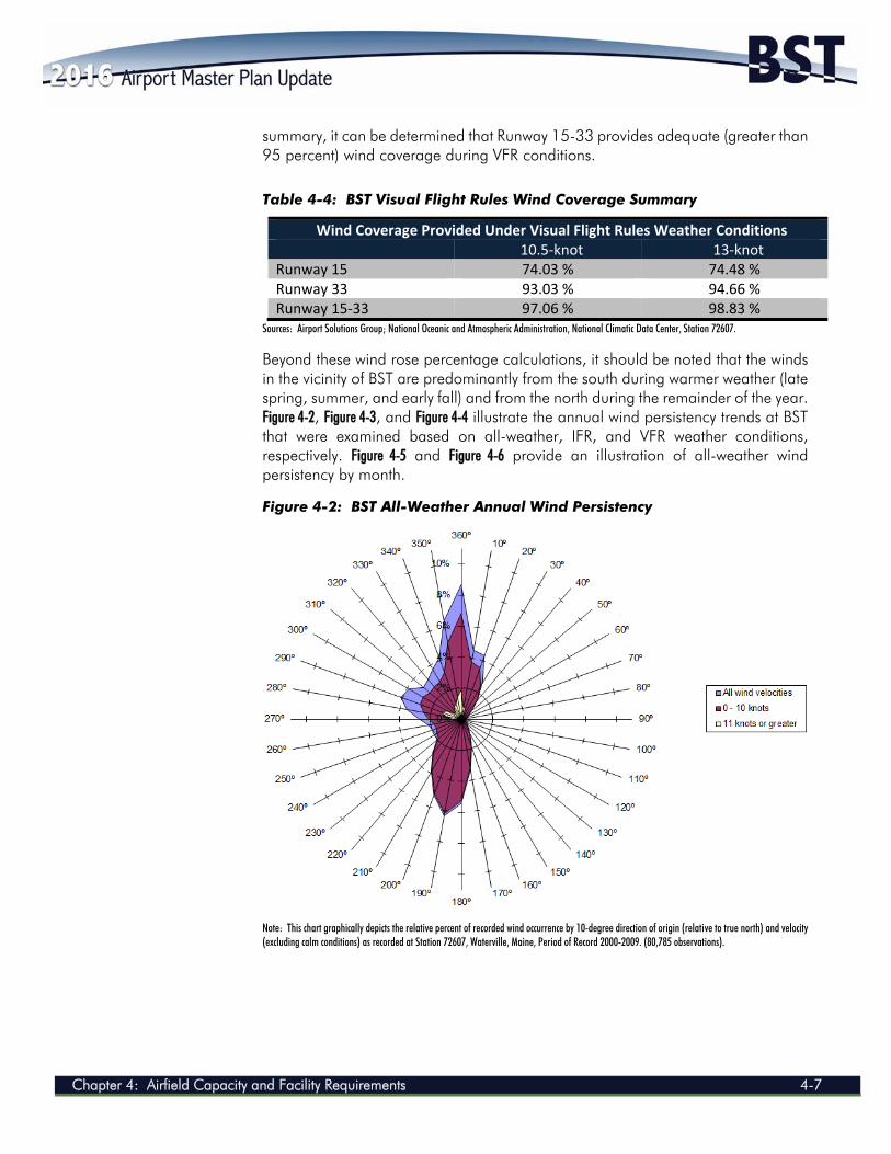
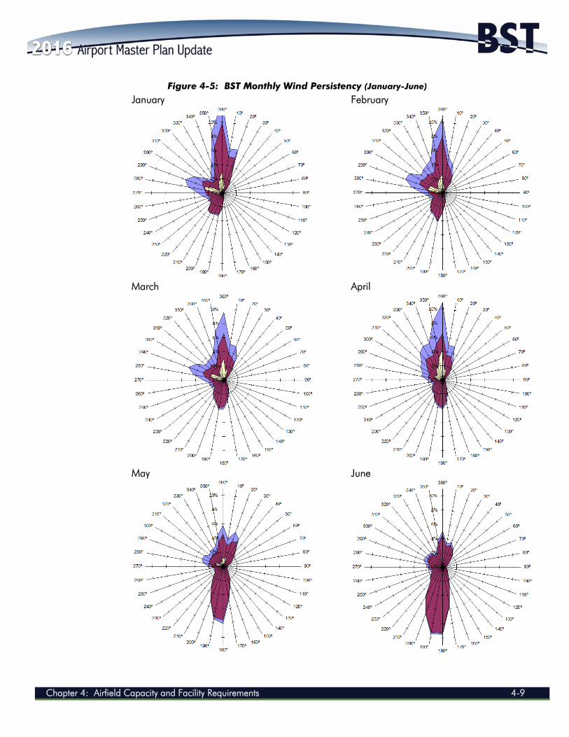
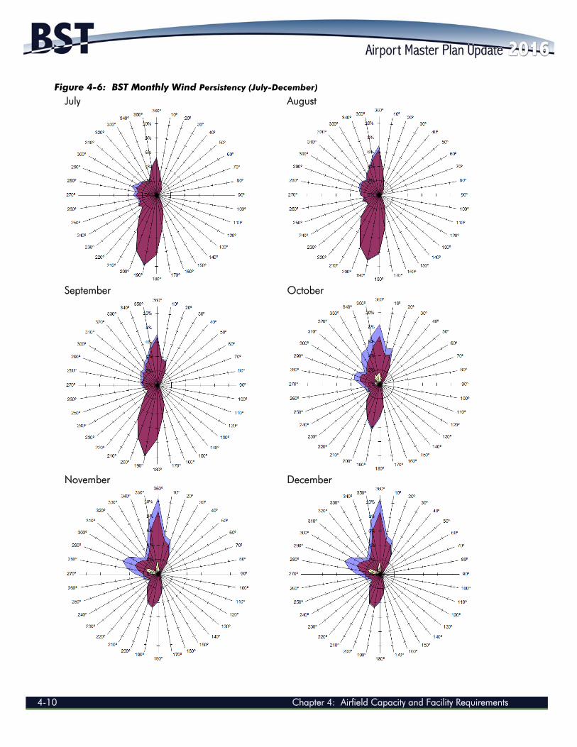
Beyond these wind rose percentage calculations, it should be noted that the winds in the vicinity of BST are predominantly from the south during warmer weather (late spring, summer, and early fall) and from the north during the remainder of the year. Figure 4-2, Figure 4-3, and Figure 4-4 illustrate the annual wind persistency trends at BST that were examined based on all-weather, IFR, and VFR weather conditions, respectively. Figure 4-5 and Figure 4-6 provide an illustration of all-weather wind persistency by month. Figure 4-2: BST All-Weather Annual Wind Persistency
Note: This chart graphically depicts the relative percent of recorded wind occurrence by 10-degree direction of origin (relative to true north) and velocity (excluding calm conditions) as recorded at Station 72607, Waterville, Maine, Period of Record 2000-2009. (80,785 observations).
AIRPORT MASTER PLAN UPDATE 2014
4-8 Chapter 4: Airfield Capacity and Facility Requirements
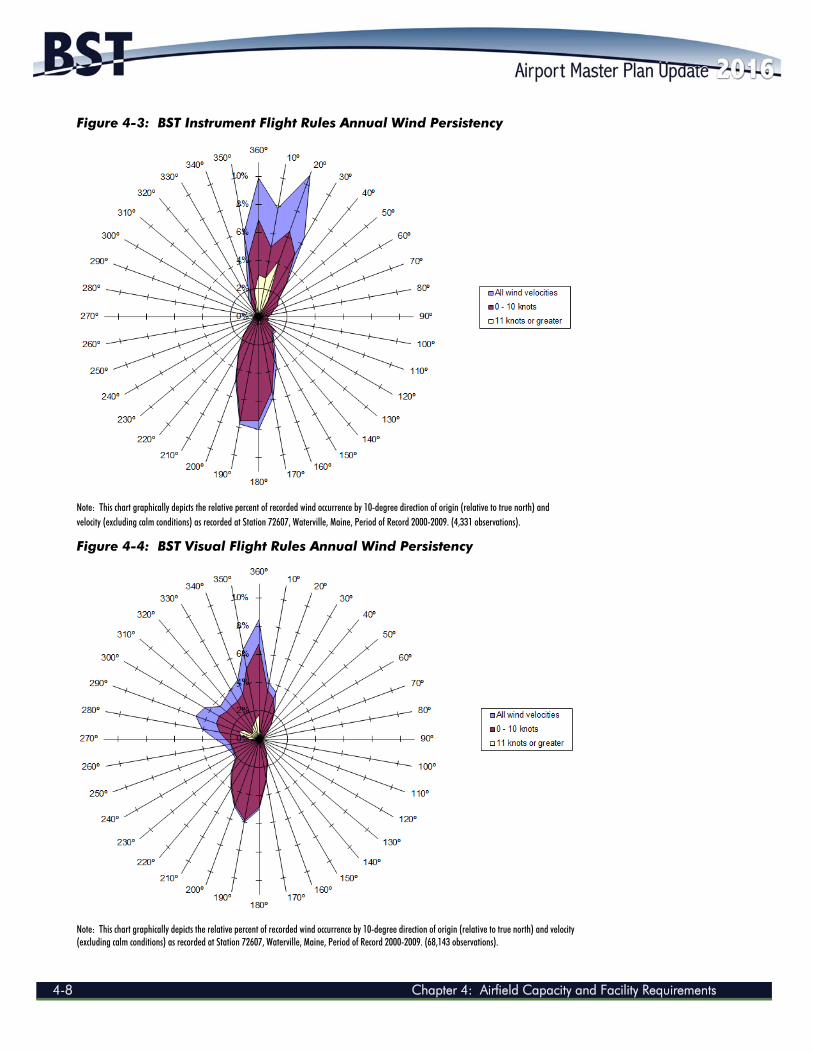
Figure 4-3: BST Instrument Flight Rules Annual Wind Persistency
Note: This chart graphically depicts the relative percent of recorded wind occurrence by 10-degree direction of origin (relative to true north) and velocity (excluding calm conditions) as recorded at Station 72607, Waterville, Maine, Period of Record 2000-2009. (4,331 observations).
Figure 4-4: BST Visual Flight Rules Annual Wind Persistency
Note: This chart graphically depicts the relative percent of recorded wind occurrence by 10-degree direction of origin (relative to true north) and velocity (excluding calm conditions) as recorded at Station 72607, Waterville, Maine, Period of Record 2000-2009. (68,143 observations).
Chapter 4: Airfield Capacity and Facility Requirements 4-9
Figure 4-5: BST Monthly Wind Persistency (January-June) January
February
March
April
May
June
AIRPORT MASTER PLAN UPDATE 2014
4-10 Chapter 4: Airfield Capacity and Facility Requirements
Figure 4-6: BST Monthly Wind Persistency (July-December) July
August
September
October
November
December
Chapter 4: Airfield Capacity and Facility Requirements 4-11
4.2.3 Airfield Capacity Calculations The calculation of airfield capacity for BST, to accommodate projected increases in aircraft operations, was conducted in accordance with procedures contained in FAA AC 150/5060-5, Airport Capacity and Delay. The airfield capacity calculations in this section were performed using the parameters and assumptions discussed above. For portions of the capacity calculations, data from the aviation demand forecast as presented in Chapter Three: Forecasts of Aviation Activity was also utilized. Applying results generated from this analysis, the optimized capacity for the Airport's runway system can be described in terms of the following results:
ASV Hourly capacity of runways (VFR and IFR)
The ASV is the maximum number of annual operations that can occur at an airport before an unacceptable operational delay is experienced. (Note that the degree at which a delay becomes “unacceptable” can vary based on the airport, but is generally accepted to be 15 minutes or more.) The ASV is calculated based on the existing runway configuration, the aircraft mix, and the parameters and assumptions identified herein. Utilizing this information and the guidance provided in FAA AC 150/5060-5, the ASV for existing conditions at BST was calculated to be approximately 230,000 operations. Additionally, with respect to hourly runway capacity under the Airport’s current runway configuration, BST has a theoretical VFR capacity of approximately 77 operations per hour and a theoretical IFR capacity of approximately 57 operations per hour. It should be noted that the ASV represents the existing airfield capacity in its present configuration, with one primary runway having non-precision instrument approach capabilities. As presented in Chapter Three, BST’s current number of aircraft operations for the base year (2014) is 10,000 operations, equaling approximately 4.3 percent of the current ASV. The highest range of forecasted operations at BST in the year 2034 is projected to be 13,208, or 5.7 percent of the current ASV. According to the FAA, the following guidelines should be used to identify necessary steps as demand reaches designated levels.
60 percent of ASV: The threshold at which planning for capacity improvements should begin.
80 percent of ASV: The threshold at which planning for improvements should be complete and construction should begin.
100 percent of ASV: The airport has reached the total number of annual operations (demand) the airport can accommodate, and capacity-enhancing improvements should be made to avoid extensive delays.
AIRPORT MASTER PLAN UPDATE 2014
4-12 Chapter 4: Airfield Capacity and Facility Requirements
Based upon existing and forecasted demand criteria, no additional airport capacity enhancing projects for the runway or taxiway system (i.e., entirely new runways or new taxiways) will be needed during the planning period. (Note that this does not include runway extensions, taxiway extensions, or new taxiways based on other criteria, such as safety or other demand.) 4.3 AIRFIELD FACILITY REQUIREMENTS Airfield facilities generally include those that support the transition of aircraft from flight to the ground or the movement of aircraft from parking or storage areas to departure and flight. This section describes the airside requirements needed to accommodate the current and projected general aviation and commercial service activity at BST throughout the planning period. Areas of particular focus include runway and taxiway dimensions, navigational aids, visual landing aids, and dimensional standards. 4.3.1 Airport Design Standards The “design aircraft” or “critical aircraft” is defined as the largest aircraft or family of aircraft anticipated to utilize a given airport on a regular basis. The FAA defines “regular basis” as conducting at least 500 annual itinerant operations (defined as an operation performed by an aircraft that lands at an airport, arriving from outside the airport area, or departs an airport and leaves the airport area). The selection of the design aircraft allows for the identification of the ARC for an airport, which itself is a coding system used to relate airport design criteria to the operational and physical characteristics of the types of aircraft intended to operate at that airport. Specifically, the ARC is an airport designation that signifies the airport’s highest RDC, which itself is comprised of the following components:
The Aircraft Approach Category (depicted by a letter and based on aircraft approach speed).
The Airplane Design Group (depicted by a Roman numeral and based on aircraft wingspan and tail height).
Table 4-5 shows the Aircraft Approach Categories and Airplane Design Groups that comprise the ARC system.
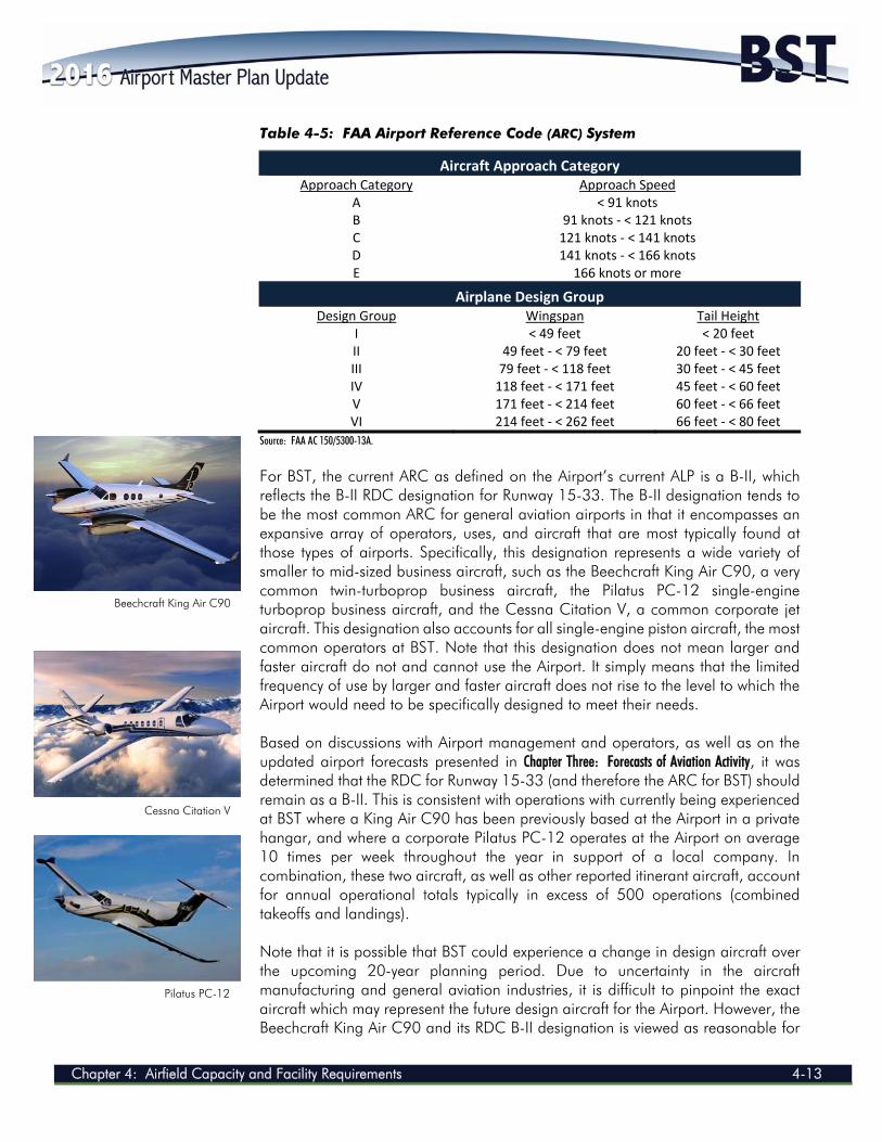
Chapter 4: Airfield Capacity and Facility Requirements 4-13
Table 4-5: FAA Airport Reference Code (ARC) System
Aircraft Approach Category Approach Category Approach Speed
A < 91 knots B 91 knots ‐ < 121 knots C 121 knots ‐ < 141 knots D 141 knots ‐ < 166 knots E 166 knots or more
Airplane Design Group Design Group Wingspan Tail Height
I < 49 feet < 20 feet II 49 feet ‐ < 79 feet 20 feet ‐ < 30 feet III 79 feet ‐ < 118 feet 30 feet ‐ < 45 feet IV 118 feet ‐ < 171 feet 45 feet ‐ < 60 feet V 171 feet ‐ < 214 feet 60 feet ‐ < 66 feet VI 214 feet ‐ < 262 feet 66 feet ‐ < 80 feet
Source: FAA AC 150/5300-13A.
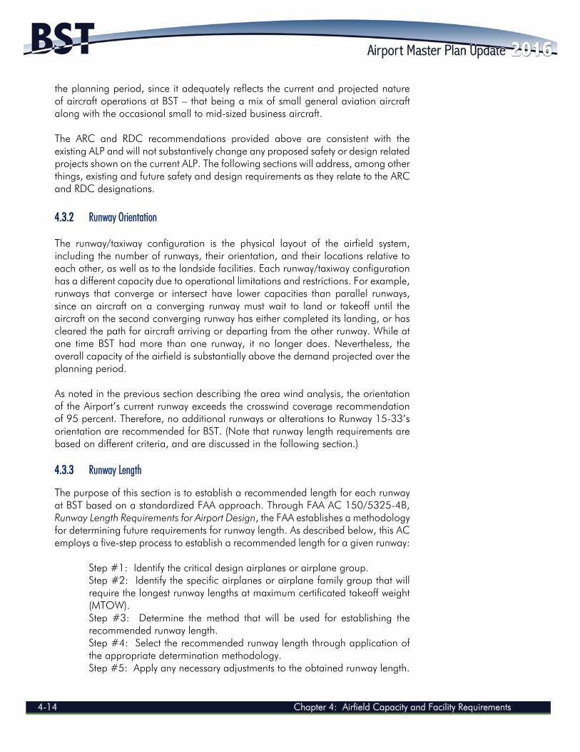
For BST, the current ARC as defined on the Airport’s current ALP is a B-II, which reflects the B-II RDC designation for Runway 15-33. The B-II designation tends to be the most common ARC for general aviation airports in that it encompasses an expansive array of operators, uses, and aircraft that are most typically found at those types of airports. Specifically, this designation represents a wide variety of smaller to mid-sized business aircraft, such as the Beechcraft King Air C90, a very common twin-turboprop business aircraft, the Pilatus PC-12 single-engine turboprop business aircraft, and the Cessna Citation V, a common corporate jet aircraft. This designation also accounts for all single-engine piston aircraft, the most common operators at BST. Note that this designation does not mean larger and faster aircraft do not and cannot use the Airport. It simply means that the limited frequency of use by larger and faster aircraft does not rise to the level to which the Airport would need to be specifically designed to meet their needs. Based on discussions with Airport management and operators, as well as on the updated airport forecasts presented in Chapter Three: Forecasts of Aviation Activity, it was determined that the RDC for Runway 15-33 (and therefore the ARC for BST) should remain as a B-II. This is consistent with operations with currently being experienced at BST where a King Air C90 has been previously based at the Airport in a private hangar, and where a corporate Pilatus PC-12 operates at the Airport on average 10 times per week throughout the year in support of a local company. In combination, these two aircraft, as well as other reported itinerant aircraft, account for annual operational totals typically in excess of 500 operations (combined takeoffs and landings). Note that it is possible that BST could experience a change in design aircraft over the upcoming 20-year planning period. Due to uncertainty in the aircraft manufacturing and general aviation industries, it is difficult to pinpoint the exact aircraft which may represent the future design aircraft for the Airport. However, the Beechcraft King Air C90 and its RDC B-II designation is viewed as reasonable for
Beechcraft King Air C90
Cessna Citation V
Pilatus PC-12
AIRPORT MASTER PLAN UPDATE 2014
4-14 Chapter 4: Airfield Capacity and Facility Requirements
the planning period, since it adequately reflects the current and projected nature of aircraft operations at BST – that being a mix of small general aviation aircraft along with the occasional small to mid-sized business aircraft. The ARC and RDC recommendations provided above are consistent with the existing ALP and will not substantively change any proposed safety or design related projects shown on the current ALP. The following sections will address, among other things, existing and future safety and design requirements as they relate to the ARC and RDC designations. 4.3.2 Runway Orientation The runway/taxiway configuration is the physical layout of the airfield system, including the number of runways, their orientation, and their locations relative to each other, as well as to the landside facilities. Each runway/taxiway configuration has a different capacity due to operational limitations and restrictions. For example, runways that converge or intersect have lower capacities than parallel runways, since an aircraft on a converging runway must wait to land or takeoff until the aircraft on the second converging runway has either completed its landing, or has cleared the path for aircraft arriving or departing from the other runway. While at one time BST had more than one runway, it no longer does. Nevertheless, the overall capacity of the airfield is substantially above the demand projected over the planning period. As noted in the previous section describing the area wind analysis, the orientation of the Airport’s current runway exceeds the crosswind coverage recommendation of 95 percent. Therefore, no additional runways or alterations to Runway 15-33’s orientation are recommended for BST. (Note that runway length requirements are based on different criteria, and are discussed in the following section.) 4.3.3 Runway Length
The purpose of this section is to establish a recommended length for each runway at BST based on a standardized FAA approach. Through FAA AC 150/5325-4B, Runway Length Requirements for Airport Design, the FAA establishes a methodology for determining future requirements for runway length. As described below, this AC employs a five-step process to establish a recommended length for a given runway:
Step #1: Identify the critical design airplanes or airplane group. Step #2: Identify the specific airplanes or airplane family group that will require the longest runway lengths at maximum certificated takeoff weight (MTOW). Step #3: Determine the method that will be used for establishing the recommended runway length. Step #4: Select the recommended runway length through application of the appropriate determination methodology. Step #5: Apply any necessary adjustments to the obtained runway length.
Chapter 4: Airfield Capacity and Facility Requirements 4-15
The following sections describe the application of each of these steps for determining a length requirement for both runways at BST. Runway 15-33 Length Recommendations Step #1: Identify the critical design airplanes or airplane group. Step #2: Identify the specific airplanes or airplane family group that will require the longest runway lengths at MTOW. In Section 4.3.1, the critical design airplane for Runway 15-33 was identified as a Beechcraft King Air C90. This is an aircraft with an RDC of B-II and a MTOW of 10,485 pounds. This is considered to be a “small” aircraft by the FAA since its MTOW is less than 12,500 pounds. Step #3: Determine the method that will be used for establishing the recommended runway length. Step #4: Select the recommended runway length through application of the appropriate determination methodology. Step #5: Apply any necessary adjustment to the obtained runway length. Step 3 simply involves identifying the appropriate runway length determination methodology provided in FAA AC 150/5325-4B that should be employed for the design aircraft. Based on Table 1-1 of the AC, the methodology described within Chapter 2 of the AC must be employed for this assessment. Step 4 is the actual runway length assessment, which is conducted through applying a series of runway or airport dependent factors to FAA runway length curves. For BST, the key dependent factors include the following:
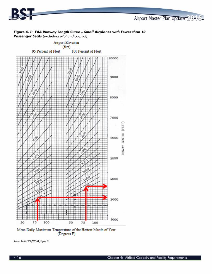
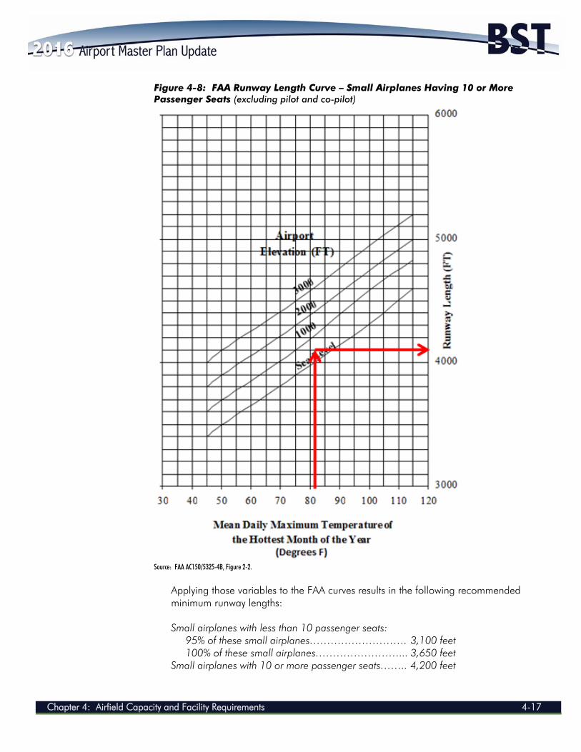
Airport elevation: 197.6 feet (Mean Seal Level - MSL) Mean daily maximum temperature (hottest month): 81°F (August) Critical design airplanes: Small aircraft (12,500 pounds or less) with
approach speeds of 50 knots or more These dependent variables are then used as inputs for the FAA runway length curves for small airplanes with fewer than 10 passenger seats and for small airplanes with 10 or more passenger seats (see Figure 4-7 and Figure 4-8, respectively).
AIRPORT MASTER PLAN UPDATE 2014
4-16 Chapter 4: Airfield Capacity and Facility Requirements
Figure 4-7: FAA Runway Length Curve – Small Airplanes with Fewer than 10 Passenger Seats (excluding pilot and co-pilot)
Source: FAA AC 150/5325-4B, Figure 2-1.
Chapter 4: Airfield Capacity and Facility Requirements 4-17
Figure 4-8: FAA Runway Length Curve – Small Airplanes Having 10 or More Passenger Seats (excluding pilot and co-pilot)
Source: FAA AC150/5325-4B, Figure 2-2.
Applying those variables to the FAA curves results in the following recommended minimum runway lengths: Small airplanes with less than 10 passenger seats: 95% of these small airplanes………………………. 3,100 feet 100% of these small airplanes……………………... 3,650 feet Small airplanes with 10 or more passenger seats…….. 4,200 feet
AIRPORT MASTER PLAN UPDATE 2014
4-18 Chapter 4: Airfield Capacity and Facility Requirements
For BST’s current and projected fleet mix, as well as for its location, the reasonable runway length is to accommodate 100% of those small airplanes with fewer than 10 passengers. As defined within the FAA AC, this classification is appropriate for airports “primarily intended to serve communities located on the fringe of a metropolitan area.” This definition is consistent with the character of BST. The fifth and final step of the FAA runway length determination process includes a review of eight potential variables that could impact an ultimate runway length requirement. However, none of these eight factors are relevant or appropriate for application at BST given the design aircraft and runway length determination approach applied above. Therefore, when following the process as stipulated in FAA AC 150/5325-4B, Runway Length Requirements for Airport Design, and when considering the existing and projected design aircraft is the Beechcraft King Air C90, the recommended minimum length for Runway 15-33 is 3,650 feet. Since Runway 15-33 is currently 4,000 feet long, it is reasonable to conclude that the existing runway length should be considered adequate for the planning period. However, FAA AC 150/5325-4B also specifically advises the following:
b. Future Airport Expansion Considerations. Airports serving small airplanes remain fairly constant in terms of the types of small airplane using the airport and their associated operational requirements. However, it is recommended that the airport designer assess and verify the airport’s ultimate development plan for realistic changes that, if overlooked, could result in future operational limitations to customers. The airport designer should at least assess and verify the impacts of:
(1) Expansions to accommodate airplanes of more than 12,500 pounds. Failure to consider this change during an initial development phase may lead to the additional expense of reconstructing or relocating facilities in the future.
For BST, this recommendation is particularly relevant since representatives (owners and facility managers) of two of BST's larger businesses, athenahealth and Front Street Shipyard, have recently inquired about the possibility of BST accommodating larger, corporate jet aircraft, both for their own business (athenahealth) and for their clients (both athenahealth and Front Street Shipyard). While there are smaller aircraft that are affiliated with these two businesses regularly using the current BST runway, there is an expressed desire to utilize aircraft that would require longer runway lengths (e.g., mid-sized corporate jet aircraft). While it was not reasonable to base the forecasts presented in Chapter Three: Forecasts of Aviation Activity on these preliminary inquiries, it is appropriate (per above) to explore this potential and the possible impacts accommodating such aircraft could have on BST’s fleet mix and on the Airport’s physical facilities.
Chapter 4: Airfield Capacity and Facility Requirements 4-19
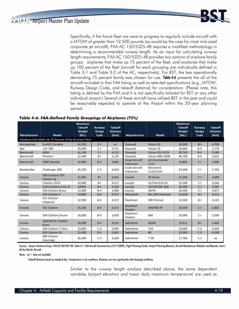
Specifically, if the future fleet mix were to progress to regularly include aircraft with a MTOW of greater than 12,500 pounds (as would be the case for most mid-sized corporate jet aircraft), FAA AC 150/5325-4B requires a modified methodology in determining a recommended runway length. As an input for calculating runway length requirements, FAA AC 150/5325-4B provides two options of airplane family groups: airplanes that make up 75 percent of the fleet, and airplanes that make up 100 percent of the fleet (aircraft for each grouping are individually defined in Table 3-1 and Table 3-2 of the AC, respectively). For BST, the less operationally demanding 75 percent family was chosen for use. Table 4-6 presents the all of the aircraft included in that FAA listing as well as selected specifications (e.g., MTOW, Runway Design Code, and takeoff distance) for consideration. (Please note, this listing is defined by the FAA and it is not specifically tailored for BST or any other individual airport.) Several of these aircraft have utilized BST in the past and could be reasonably expected to operate at the Airport within the 20-year planning period.
Table 4-6: FAA-Defined Family Groupings of Airplanes (75%)
Manufacturer Model
Maximum Takeoff Weight (lbs.)
Runway Design Code
Takeoff Distance (feet) Manufacturer Model
Maximum Takeoff Weight (lbs.)
Runway Design Code
Takeoff Distance (feet)
Airplanes that Make Up 75 Percent of the Business Fleet
Aerospatiale Sn‐601 Corvette 14,550 C‐I na Dassault Falcon 10 18,300 B‐I 4,700
Bae 125‐700 25,000 C‐I 5,751 Dassault Falcon 20 28,660 B‐II 5,170 Beechcraft 400A 16,100 C‐I 4,515 Dassault Falcon 50/ 50 EX 39,700 B‐II 5,589 Beechcraft Premier I 12,500 B‐I 3,125 Dassault Falcon 900/ 900B 46,700 B‐II 5,651
Beechcraft 2000 Starship 14,900 B‐II 3,845 Israel Aircraft Industries
Jet Commander 1121
16,800 C‐I 5,000
Bombardier Challenger 300 41,250 C‐II 4,810 Israel Aircraft Industries
Westwind 1123/1124
23,500 C‐I 5,750
Cessna 500 Citation/ 501 Citation Sp
11,850 B‐I 3,642 Learjet 20 Series 12,500 C‐I 3,600
Cessna Citation I/II/III 10,600 B‐I 4,317 Learjet 31/31A/31A ER 15,500 C‐I 3,266 Cessna 525A Citation II (CJ‐2) 10400 B‐I 4,183 Learjet 35/35A/36/ 36A 18,300 C‐I 5,581 Cessna 550 Citation Bravo 13,300 B‐II 3,600 Learjet 40/45 20,500 C‐I 4,877 Cessna 550 Citation II 14,800 B‐II 4,317 Mitsubishi Mu‐300 Diamond 14,630 B‐I 4,515
Cessna 551 Citation II/Special
12,500 B‐II 4,317 Raytheon 390 Premier 12,500 B‐I 3,125
Cessna 552 Citation 15,100 B‐II 4,317 Raytheon Hawker
400/400 XP 23,300 C‐I 3,802
Cessna 560 Citation Encore 16,830 B‐II 3,639 Raytheon Hawker
600 25,000 C‐I 5,030
Cessna 560/560 XL Citation Excel
20,000 B‐II 4,214 Sabreliner 40/60 19,612 B‐I 5,663
Cessna 560 Citation V Ultra 23,000 C‐II 5,605 Sabreliner 75A 24,000 C‐II 6,356 Cessna 650 Citation VII 22,000 B‐II 5,605 Sabreliner 80 23,300 C‐II 6,200
Cessna 680 Citation Sovereign
30,300 C‐II 3,650 Sabreliner T‐39 17,760 C‐I na
Sources: Airport Solutions Group; FAA AC150/5325-4B, Table 3-1; FAA Aircraft Characteristics (12/11/2009); Flight Planning Guides, Airport Planning Manuals, Aircraft Manufacturer Websites and Manuals, Jane's All the World's Aircraft .
Notes: na = data not available.
Takeoff distances based on standard day / temperature in dry conditions. Distances con vary significantly with changing conditions.
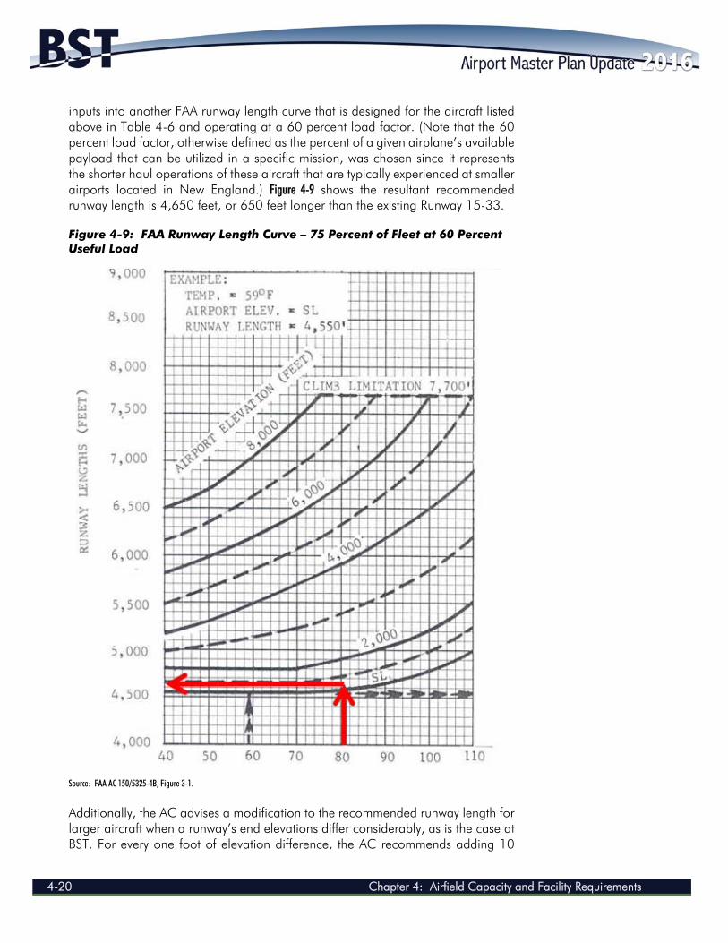
Similar to the runway length analysis described above, the same dependent variables (airport elevation and mean daily maximum temperature) are used as
AIRPORT MASTER PLAN UPDATE 2014
4-20 Chapter 4: Airfield Capacity and Facility Requirements
inputs into another FAA runway length curve that is designed for the aircraft listed above in Table 4-6 and operating at a 60 percent load factor. (Note that the 60 percent load factor, otherwise defined as the percent of a given airplane’s available payload that can be utilized in a specific mission, was chosen since it represents the shorter haul operations of these aircraft that are typically experienced at smaller airports located in New England.) Figure 4-9 shows the resultant recommended runway length is 4,650 feet, or 650 feet longer than the existing Runway 15-33. Figure 4-9: FAA Runway Length Curve – 75 Percent of Fleet at 60 Percent Useful Load
Source: FAA AC 150/5325-4B, Figure 3-1.
Additionally, the AC advises a modification to the recommended runway length for larger aircraft when a runway’s end elevations differ considerably, as is the case at BST. For every one foot of elevation difference, the AC recommends adding 10
Chapter 4: Airfield Capacity and Facility Requirements 4-21
feet to the recommended runway length. For BST, there is an approximately 39-foot elevation difference in the runway end elevations (197.6 MSL versus 158.5 above mean sea level) which translates into an additional 390 feet of recommended runway length. Therefore, this methodology would result in an FAA-recommended minimum runway length of 5,040 feet. Runway Length Recommendations BST’s current ALP shows an ultimate runway length of 4,000 feet for Runway 15-33, which is adequate for the runway’s existing and projected design aircraft (Beechcraft King Air C90) throughout the planning period. However, in compliance with the recommendation in FAA AC 150/5325-4B that small airports factor in potential future runway length requirements beyond those that may be currently projected, BST should consider planning for a longer runway. The FAA process in determining a minimum recommended runway length has been detailed above and is summarized in the following:
Step #1: Identify the critical design airplanes or airplane group - For BST, this was identified as the Beechcraft King Air C90.
Step #2: Identify the specific airplanes or airplane family group that will require the longest runway lengths at MTOW. - For BST, this was the airplane family grouping defined as “small airplanes with fewer than 10 passenger seats.”
Step #3: Determine the method that will be used for establishing the recommended runway length - For BST, the design guidelines located in Chapter 2, Paragraph 205, Figure 2-1 and Figure 2-2 of FAA AC 150/5325-4B were applied.
Step #4: Select the recommended runway length through application of the appropriate determination methodology - For BST, results from both Figure 2-1 and Figure 2-2 were considered, with the conclusion being that BST should accommodate 100% of the fleet mix associated with small airplanes with fewer than 10 passenger seats. This results in a runway length requirement of 3,650 feet.
Step #5: Apply any necessary adjustment to the obtained runway length. - For BST, in anticipation of increased business aircraft demand in terms of both quantity and aircraft size, Chapter 3, Paragraph 306, Figure 3-1 of FAA AC 150/5325-4B was considered. Based on the airplane family group “Airplanes that Make Up 75 Percent of the Fleet” and when considering the most conservative scenario (i.e., “75 percent of fleet at 60 percent useful load”), and when considering a correction factor associated with BST’s runway end elevations, a minimum recommended runway length of 5,040 feet was determined.
Note that this additional length would only be required if the actual demand related to those inquiries were to be realized. Additionally, it should be understood that
AIRPORT MASTER PLAN UPDATE 2014
4-22 Chapter 4: Airfield Capacity and Facility Requirements
simply because a limited demand for a longer runway may develop, that demand may not rise to a level that would convince the FAA to fund such a runway extension, and would therefore require some form of public-private partnership to bring it to fruition. Nevertheless, it is important that this possibility be considered and reflected in this AMPU. 4.3.4 Runway Width The required width of a runway is defined in FAA AC 150/5300-13A, Airport Design, and is a function of the RDC and the instrumentation available for the approach. Runway 15-33 is currently 100 feet wide, has an RDC of B-II and is equipped with multiple non-precision instrument approaches. While the FAA AC’s recommended width for Runway 15-33 is 75 feet, the FAA does provide for allowances for a “greater than required” runway width for those airports without a crosswind runway. Specifically, this is due to the fact that smaller aircraft are extremely susceptible to strong and variable winds (including quartering headwinds, variable crosswinds and gusts, etc.) during takeoff and landing operations. Such crosswinds can easily blow a pilot off his runway centerline track and requires a pilot to perform a crosswind approach, which includes “crabbing” into the wind (i.e., a technique where the aircraft nose points into the wind so that the aircraft approaches the runway slightly skewed with respect to the runway centerline). Regardless of the technique, a wider runway provides a pilot with enhanced flexibility to safely and appropriately respond to a crosswind condition. The FAA recognizes this condition and understands the potential implications are most critical at a single runway airport where pilots have limited runway options. Therefore, the FAA has endorsed maintaining the existing runway width of 100 feet in order to maintain the overall level of safety for Runway 15-33. 4.3.5 Pavement Strength There are several factors that must be considered when determining the appropriate pavement strength for a given runway. These factors include, but are not limited to: aircraft loads; frequency and concentration of operations; and the condition of subgrade soils. Runway pavement strength is typically expressed by common landing gear configurations, which include the following:
Single-wheel: Each landing gear unit has a single tire; example aircraft include light aircraft and some business jet aircraft.
Dual-wheel: Each landing gear unit has two tires;, example aircraft are the Boeing 737, Boeing 727, MD-80, CRJ 200, and the Dash 8.
Dual-tandem: The main landing gear unit has four tires arranged in the shape of a square; example aircraft are the Boeing 707 and KC135.
The aircraft gear configuration dictates how aircraft weight is distributed to the pavement and determines pavement response to loading. It should be noted that operations by aircraft that exceed a runway’s pavement strength will degrade the
Chapter 4: Airfield Capacity and Facility Requirements 4-23
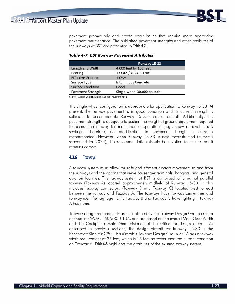
pavement prematurely and create wear issues that require more aggressive pavement maintenance. The published pavement strengths and other attributes of the runways at BST are presented in Table 4-7.
Table 4-7: BST Runway Pavement Attributes
Runway 15‐33 Length and Width 4,000 feet by 100 feet Bearing 133.42°/313.43° True Effective Gradient 1.0%±‐ Surface Type Bituminous Concrete Surface Condition Good Pavement Strength Single‐wheel 30,000 pounds
Sources: Airport Solutions Group; BST ALP; FAA Form 5010.
The single-wheel configuration is appropriate for application to Runway 15-33. At present, the runway pavement is in good condition and its current strength is sufficient to accommodate Runway 15-33’s critical aircraft. Additionally, this pavement strength is adequate to sustain the weight of ground equipment required to access the runway for maintenance operations (e.g., snow removal, crack sealing). Therefore, no modification to pavement strength is currently recommended. However, when Runway 15-33 is next reconstructed (currently scheduled for 2024), this recommendation should be revisited to ensure that it remains correct. 4.3.6 Taxiways A taxiway system must allow for safe and efficient aircraft movement to and from the runways and the aprons that serve passenger terminals, hangars, and general aviation facilities. The taxiway system at BST is comprised of a partial parallel taxiway (Taxiway A) located approximately midfield of Runway 15-33. It also includes taxiway connectors (Taxiway B and Taxiway C) located west to east between the runway and Taxiway A. The taxiways have taxiway centerlines and runway identifier signage. Only Taxiway B and Taxiway C have lighting – Taxiway A has none. Taxiway design requirements are established by the Taxiway Design Group criteria defined in FAA AC 150/5300-13A, and are based on the overall Main Gear Width and the Cockpit to Main Gear distance of the critical or design aircraft. As described in previous sections, the design aircraft for Runway 15-33 is the Beechcraft King Air C90. This aircraft’s Taxiway Design Group of 1A has a taxiway width requirement of 25 feet, which is 15 feet narrower than the current condition on Taxiway A. Table 4-8 highlights the attributes of the existing taxiway system.
AIRPORT MASTER PLAN UPDATE 2014
4-24 Chapter 4: Airfield Capacity and Facility Requirements
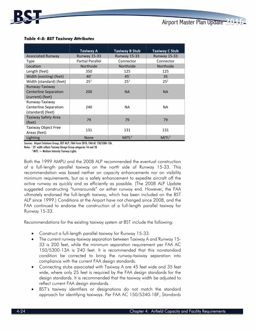
Table 4-8: BST Taxiway Attributes
Taxiway A Taxiway B Stub Taxiway C Stub Associated Runway Runway 15‐33 Runway 15‐33 Runway 15‐33 Type Partial Parallel Connector Connector Location Northside Northside Northside Length (feet) 350 125 125 Width (existing) (feet) 40' 45' 35 Width (standard) (feet) 251 251 251 Runway‐Taxiway Centerline Separation (current) (feet)
200 NA NA
Runway‐Taxiway Centerline Separation (standard) (feet)
240 NA NA
Taxiway Safety Area (feet)
79 79 79
Taxiway Object Free Areas (feet)
131 131 131
Lighting None MITL2 MITL2
Sources: Airport Solutions Group; BST ALP; FAA Form 5010; FAA AC 150/5300-13A. Notes: 1 25’ width reflects Taxiway Design Group categories 1A and 1B. 2 MITL = Medium Intensity Taxiway Lights.
Both the 1999 AMPU and the 2008 ALP recommended the eventual construction of a full-length parallel taxiway on the north side of Runway 15-33. This recommendation was based neither on capacity enhancements nor on visibility minimum requirements, but as a safety enhancement to expedite aircraft off the active runway as quickly and as efficiently as possible. (The 2008 ALP Update suggested constructing “turnarounds” on either runway end. However, the FAA ultimately endorsed the full-length taxiway, which has been included on the BST ALP since 1999.) Conditions at the Airport have not changed since 2008, and the FAA continued to endorse the construction of a full-length parallel taxiway for Runway 15-33. Recommendations for the existing taxiway system at BST include the following:
Construct a full-length parallel taxiway for Runway 15-33. The current runway-taxiway separation between Taxiway A and Runway 15-
33 is 200 feet, while the minimum separation requirement per FAA AC 150/5300-13A is 240 feet. It is recommended that this nonstandard condition be corrected to bring the runway-taxiway separation into compliance with the current FAA design standards.
Connecting stubs associated with Taxiway A are 45 feet wide and 35 feet wide, where only 25 feet is required by the FAA design standards for the design standards. It is recommended that the taxiway width be adjusted to reflect current FAA design standards.
BST’s taxiway identifiers or designations do not match the standard approach for identifying taxiways. Per FAA AC 150/5340-18F, Standards
Chapter 4: Airfield Capacity and Facility Requirements 4-25
for Airport Sign Systems, it is recommended that the taxiway identifier system be developed in a simple and logical fashion and that connecting taxiways should reflect the primary taxiway that they support. Therefore, it is recommended that the taxiways be re-identified to reflect the current standards for identification.
It should also be acknowledged that additional taxiways may be necessary in the future to access any newly developed apron or hangar areas. Any proposed landside development should include taxiways or taxilanes (used to access various apron areas, including tie downs and hangars) if they are intended to provide aircraft access to the airfield. Future taxiways or taxilanes to meet this need will be illustrated on a future ALP. 4.3.7 Navigational Aids
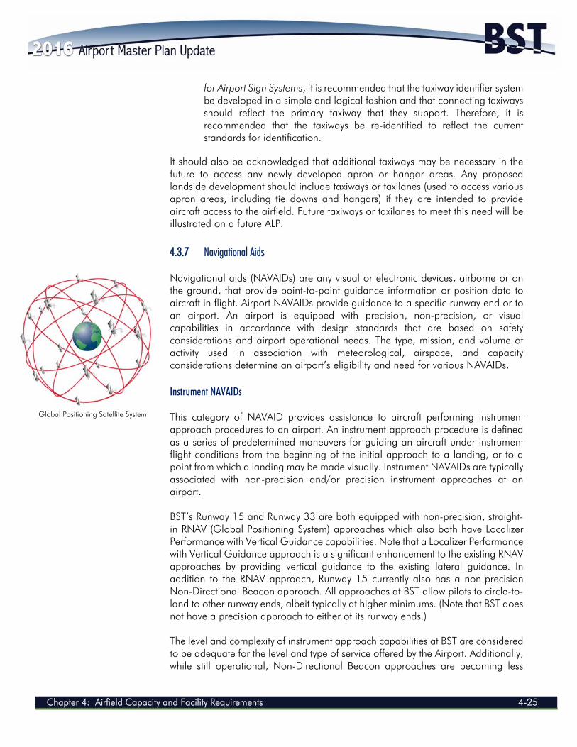
Navigational aids (NAVAIDs) are any visual or electronic devices, airborne or on the ground, that provide point-to-point guidance information or position data to aircraft in flight. Airport NAVAIDs provide guidance to a specific runway end or to an airport. An airport is equipped with precision, non-precision, or visual capabilities in accordance with design standards that are based on safety considerations and airport operational needs. The type, mission, and volume of activity used in association with meteorological, airspace, and capacity considerations determine an airport’s eligibility and need for various NAVAIDs. Instrument NAVAIDs This category of NAVAID provides assistance to aircraft performing instrument approach procedures to an airport. An instrument approach procedure is defined as a series of predetermined maneuvers for guiding an aircraft under instrument flight conditions from the beginning of the initial approach to a landing, or to a point from which a landing may be made visually. Instrument NAVAIDs are typically associated with non-precision and/or precision instrument approaches at an airport. BST’s Runway 15 and Runway 33 are both equipped with non-precision, straight-in RNAV (Global Positioning System) approaches which also both have Localizer Performance with Vertical Guidance capabilities. Note that a Localizer Performance with Vertical Guidance approach is a significant enhancement to the existing RNAV approaches by providing vertical guidance to the existing lateral guidance. In addition to the RNAV approach, Runway 15 currently also has a non-precision Non-Directional Beacon approach. All approaches at BST allow pilots to circle-to-land to other runway ends, albeit typically at higher minimums. (Note that BST does not have a precision approach to either of its runway ends.) The level and complexity of instrument approach capabilities at BST are considered to be adequate for the level and type of service offered by the Airport. Additionally, while still operational, Non-Directional Beacon approaches are becoming less
Global Positioning Satellite System
AIRPORT MASTER PLAN UPDATE 2014
4-26 Chapter 4: Airfield Capacity and Facility Requirements
common due to their lack of precision and the cost of maintaining outdated equipment. Therefore, the Airport should consider decommissioning this approach at some future date. However, it is also recommended that the Airport continue to maintain all its other approaches and their ancillary support features. Visual Landing Aids Visual landing aids provide aircraft guidance to and alignment with a specific runway end, once the airport is within a pilot’s sight. Visual landing aids at BST currently include the following:
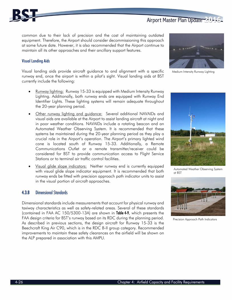
Runway lighting: Runway 15-33 is equipped with Medium Intensity Runway Lighting. Additionally, both runway ends are equipped with Runway End Identifier Lights. These lighting systems will remain adequate throughout the 20-year planning period.
Other runway lighting and guidance: Several additional NAVAIDs and visual aids are available at the Airport to assist landing aircraft at night and in poor weather conditions. NAVAIDs include a rotating beacon and an Automated Weather Observing System. It is recommended that these systems be maintained during the 20-year planning period as they play a crucial role in the Airport’s operation. The Airport’s primary lighted wind cone is located south of Runway 15-33. Additionally, a Remote Communications Outlet or a remote transmitter/receiver could be considered for BST to provide communication access to Flight Service Stations or to terminal air traffic control facilities.
Visual glide slope indicators: Neither runway end is currently equipped with visual glide slope indicator equipment. It is recommended that both runway ends be fitted with precision approach path indicator units to assist in the visual portion of aircraft approaches.
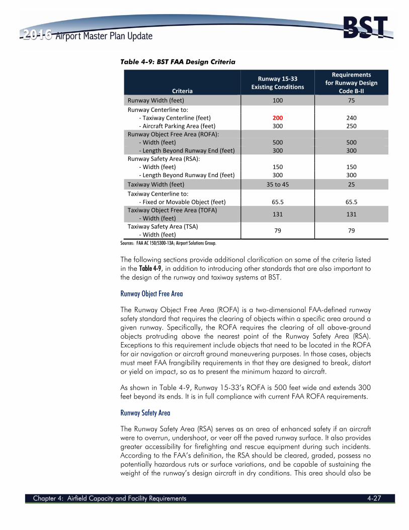
4.3.8 Dimensional Standards Dimensional standards include measurements that account for physical runway and taxiway characteristics as well as safety-related areas. Several of these standards (contained in FAA AC 150/5300-13A) are shown in Table 4-9, which presents the FAA design criteria for BST’s runway based on its RDC during the planning period. As described in previous sections, the design aircraft for Runway 15-33 is the Beechcraft King Air C90, which is in the RDC B-II group category. Recommended improvements to maintain these safety clearances on the airfield will be shown on the ALP prepared in association with this AMPU.
Precision Approach Path Indicators
Medium Intensity Runway Lighting
Automated Weather Observing System at BST
Chapter 4: Airfield Capacity and Facility Requirements 4-27
Table 4-9: BST FAA Design Criteria
Criteria
Runway 15‐33 Existing Conditions
Requirements for Runway Design
Code B‐II
Runway Width (feet) 100 75
Runway Centerline to: ‐ Taxiway Centerline (feet) 200 240 ‐ Aircraft Parking Area (feet) 300 250
Runway Object Free Area (ROFA): ‐ Width (feet) 500 500 ‐ Length Beyond Runway End (feet) 300 300
Runway Safety Area (RSA): ‐ Width (feet) 150 150 ‐ Length Beyond Runway End (feet) 300 300
Taxiway Width (feet) 35 to 45 25
Taxiway Centerline to: ‐ Fixed or Movable Object (feet) 65.5 65.5
Taxiway Object Free Area (TOFA) ‐ Width (feet)
131 131
Taxiway Safety Area (TSA) ‐ Width (feet)
79 79
Sources: FAA AC 150/5300-13A; Airport Solutions Group.
The following sections provide additional clarification on some of the criteria listed in the Table 4-9, in addition to introducing other standards that are also important to the design of the runway and taxiway systems at BST.
Runway Object Free Area The Runway Object Free Area (ROFA) is a two-dimensional FAA-defined runway safety standard that requires the clearing of objects within a specific area around a given runway. Specifically, the ROFA requires the clearing of all above-ground objects protruding above the nearest point of the Runway Safety Area (RSA). Exceptions to this requirement include objects that need to be located in the ROFA for air navigation or aircraft ground maneuvering purposes. In those cases, objects must meet FAA frangibility requirements in that they are designed to break, distort or yield on impact, so as to present the minimum hazard to aircraft. As shown in Table 4-9, Runway 15-33’s ROFA is 500 feet wide and extends 300 feet beyond its ends. It is in full compliance with current FAA ROFA requirements.
Runway Safety Area The Runway Safety Area (RSA) serves as an area of enhanced safety if an aircraft were to overrun, undershoot, or veer off the paved runway surface. It also provides greater accessibility for firefighting and rescue equipment during such incidents. According to the FAA’s definition, the RSA should be cleared, graded, possess no potentially hazardous ruts or surface variations, and be capable of sustaining the weight of the runway’s design aircraft in dry conditions. This area should also be
AIRPORT MASTER PLAN UPDATE 2014
4-28 Chapter 4: Airfield Capacity and Facility Requirements
drained through application of appropriate grading or storm drains. (Note that general requirements for grading of the RSA are 0 to –3 degree grade for the first 200 feet from the runway end, with the remaining longitudinal grade ensuring that no part of the RSA penetrates the approach surface or drops below a –5 degree grade.) Objects that must be located in the RSA for air navigation or aircraft ground maneuvering purposes must meet FAA frangibility requirements. As shown in Table 4-9, Runway 15-33’s RDC B-II dictates that its RSA be 150 feet wide and extend 300 feet beyond its ends. It is in full compliance with current FAA RSA requirements. Obstacle Free Zones The Obstacle Free Zone (OFZ) is a three-dimensional volume of airspace that supports the transition of ground-to-airborne operations (or vice versa). The OFZ clearing standards prohibit taxiing and parked airplanes and other objects, except frangible NAVAIDs or those FAA-required objects, from penetrating this zone. The OFZ consists of a volume of airspace below 150 feet above the established Airport elevation and is centered on the runway and extended runway centerline. The Runway Obstacle Free Zone (ROFZ) consists of a volume of airspace centered above the runway centerline, above a surface whose elevation at any point is the same as the elevation of the nearest point on the runway centerline. The ROFZ extends 200 feet beyond each end of the runway and has a width that varies with approach visibility minimums and the size of aircraft using the runway. Runway Protection Zones A Runway Protection Zone (RPZ) is an area off the runway end intended to enhance the protection of people and property on the ground. RPZ size is a function of critical aircraft and the visibility minimums established for the approach to the runway. Visual runways have smaller RPZs because the landing minimums are higher and the runway is not used during periods of reduced visibility. Essentially, the greater precision of the approach, the lower the visibility minimums for landing, the larger the required RPZ. The existing RPZs at BST will be evaluated in Chapter Five: Alternatives Analysis and Development Concepts and any required modifications, including the acquisition of land to be compatible with Airport uses, will be identified. The RPZ contains two sub-areas; these areas are discussed as follows:
ROFA: The ROFA is a two-dimensional ground area surrounding the runway that prohibits parked aircraft and objects, except NAVAIDs and objects with locations fixed by function, from locating there. Per FAA design guidelines shown previously in Table 4-9, the ROFA for RDC B-II runways should extend 300 feet beyond each runway end and have a width of 500 feet.
Controlled Activity Area: The controlled activity area is the portion of the RPZ beyond and to the sides of the ROFA. It is recommended that an airport
Chapter 4: Airfield Capacity and Facility Requirements 4-29
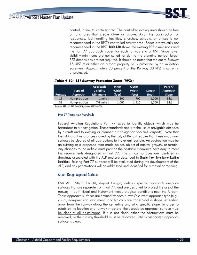
control, in fee, this activity area. The controlled activity area should be free of land uses that create glare or smoke. Also, the construction of residences, fuel-handling facilities, churches, schools, or offices is not recommended in the RPZ’s controlled activity area. Roads are typically not recommended in the RPZ. Table 4-10 shows the existing RPZ dimensions and the Part 77 approach slopes for each runway end at BST. Since lower visibility minimums are not called for during the planning period, larger RPZ dimensions are not required. It should be noted that the entire Runway 15 RPZ rests either on airport property or is protected by an avigation easement. Approximately 30 percent of the Runway 33 RPZ is currently unprotected.
Table 4-10: BST Runway Protection Zones (RPZs)
Runway Type of Approach
Approach Visibility Minimums
Inner Width (feet)
Outer Width (feet)
Length (feet)
Part 77 Approach Slope
15 Non‐precision 1 mile 500 700 1,000 34:1 33 Non‐precision 7/8 mile 1,000 1,510 1,700 34:1
Sources: BST ALP; FAA Form 5010; FAA AC 150/5300-13A.
Part 77 Obstruction Standards Federal Aviation Regulations Part 77 exists to identify objects which may be hazardous to air navigation. These standards apply to the use of navigable airspace by aircraft and to existing or planned air navigation facilities (airports). Note that the FAA grant assurances signed by the City of Belfast require that these imaginary surfaces be cleared of all obstructions to the extent feasible. An obstruction may be an existing or a proposed man-made object, object of natural growth, or terrain. Any changes to the airfield must provide the obstacle clearance necessary to meet the requirements designated in Part 77. The critical surfaces are identified in drawings associated with the ALP and are described in Chapter Two: Inventory of Existing Conditions. Existing Part 77 surfaces will be evaluated during the development of the ALP, and any penetrations will be addressed and identified for removal or marking. Airport Design Approach Surfaces FAA AC 150/5300-13A, Airport Design, defines specific approach airspace surfaces that are separate from Part 77, and are designed to protect the use of the runway in both visual and instrument meteorological conditions near the Airport. These approach surfaces are defined by each runway’s current approach type (e.g., visual, non-precision instrument), and typically are trapezoidal in shape, extending away from the runway along the centerline and at a specific slope. In order to establish the location of a runway threshold, the associated approach surface must be clear of all obstructions. If it is not clear, either the obstructions must be removed, or the runway threshold must be relocated until its associated approach surface is clear.
AIRPORT MASTER PLAN UPDATE 2014
4-30 Chapter 4: Airfield Capacity and Facility Requirements
At the time of this AMPU effort, BST was undertaking an obstruction clearance effort for the Runway 15 approach end as part of an FAA-funded project, anticipated to be completed by April of 2017. 4.4 LANDSIDE FACILITY REQUIREMENTS
This section describes the landside facility requirements needed to accommodate BST’s general aviation activity throughout the planning period. Areas of particular focus include the terminal/administration building, hangars, aprons and tie down areas, automobile parking, access, as well as the various associated support facilities. 4.4.1 Terminal / Administration Building
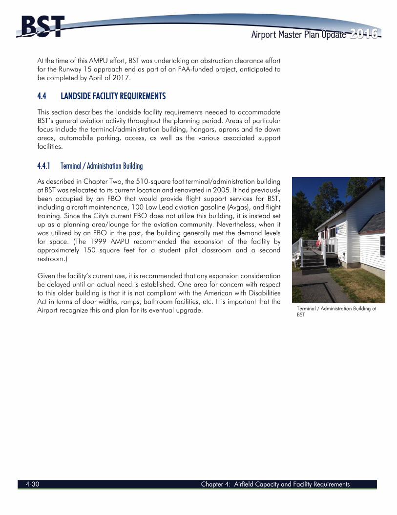
As described in Chapter Two, the 510-square foot terminal/administration building at BST was relocated to its current location and renovated in 2005. It had previously been occupied by an FBO that would provide flight support services for BST, including aircraft maintenance, 100 Low Lead aviation gasoline (Avgas), and flight training. Since the City's current FBO does not utilize this building, it is instead set up as a planning area/lounge for the aviation community. Nevertheless, when it was utilized by an FBO in the past, the building generally met the demand levels for space. (The 1999 AMPU recommended the expansion of the facility by approximately 150 square feet for a student pilot classroom and a second restroom.) Given the facility’s current use, it is recommended that any expansion consideration be delayed until an actual need is established. One area for concern with respect to this older building is that it is not compliant with the American with Disabilities Act in terms of door widths, ramps, bathroom facilities, etc. It is important that the Airport recognize this and plan for its eventual upgrade.
Terminal / Administration Building at BST
Chapter 4: Airfield Capacity and Facility Requirements 4-31
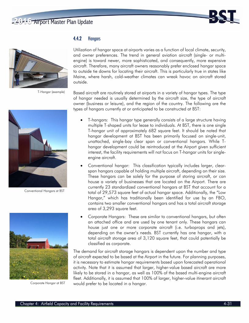
4.4.2 Hangars Utilization of hangar space at airports varies as a function of local climate, security, and owner preferences. The trend in general aviation aircraft (single- or multi-engine) is toward newer, more sophisticated, and consequently, more expensive aircraft. Therefore, many aircraft owners reasonably prefer enclosed hangar space to outside tie downs for locating their aircraft. This is particularly true in states like Maine, where harsh, cold-weather climates can wreak havoc on aircraft stored outside. Based aircraft are routinely stored at airports in a variety of hangar types. The type of hangar needed is usually determined by the aircraft size, the type of aircraft owner (business or leisure), and the region of the country. The following are the types of hangars currently at or anticipated to be constructed at BST:
T-hangars: This hangar type generally consists of a large structure having multiple T-shaped units for lease to individuals. At BST, there is one single T-hangar unit of approximately 682 square feet. It should be noted that hangar development at BST has been primarily focused on single-unit, unattached, single-bay clear span or conventional hangars. While T-hangar development could be reintroduced at the Airport given sufficient interest, the facility requirements will not focus on T-hangar units for single-engine aircraft.
Conventional hangar: This classification typically includes larger, clear-span hangars capable of holding multiple aircraft, depending on their size. These hangars can be solely for the purpose of storing aircraft, or can house a variety of businesses that are located on the Airport. There are currently 23 standardized conventional hangars at BST that account for a total of 29,573 square feet of actual hangar space. Additionally, the “Low Hangar,” which has traditionally been identified for use by an FBO, contains two smaller conventional hangars and has a total aircraft storage area of 3,293 square feet.
Corporate Hangars: These are similar to conventional hangars, but often an attached office and are used by one tenant only. These hangars can house just one or more corporate aircraft (i.e. turboprops and jets), depending on the owner’s needs. BST currently has one hangar, with a total aircraft storage area of 3,120 square feet, that could potentially be classified as corporate.
The demand for aircraft storage hangars is dependent upon the number and type of aircraft expected to be based at the Airport in the future. For planning purposes, it is necessary to estimate hangar requirements based upon forecasted operational activity. Note that it is assumed that larger, higher-value based aircraft are more likely to be stored in a hangar, as well as 100% of the based multi-engine aircraft fleet. Additionally, it is assumed that 100% of larger, higher-value itinerant aircraft would prefer to be located in a hangar.
T-Hangar (example)
Conventional Hangars at BST
Corporate Hangar at BST
AIRPORT MASTER PLAN UPDATE 2014
4-32 Chapter 4: Airfield Capacity and Facility Requirements
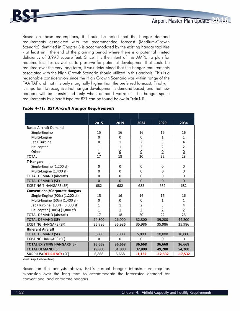
Based on those assumptions, it should be noted that the hangar demand requirements associated with the recommended forecast (Medium-Growth Scenario) identified in Chapter 3 is accommodated by the existing hangar facilities - at least until the end of the planning period where there is a potential limited deficiency of 3,993 square feet. Since it is the intent of this AMPU to plan for required facilities as well as to preserve for potential development that could be required over the very long term, it was determined that the hangar requirements associated with the High Growth Scenario should utilized in this analysis. This is a reasonable consideration since the High Growth Scenario was within range of the FAA TAF and that it is only marginally higher than the preferred forecast. Finally, it is important to recognize that hangar development is demand based, and that new hangars will be constructed only when demand warrants. The hangar space requirements by aircraft type for BST can be found below in Table 4-11. Table 4-11: BST Aircraft Hangar Requirements
2015 2019 2024 2029 2034 Based Aircraft Demand Single‐Engine 15 16 16 16 16 Multi‐Engine 0 0 0 1 1 Jet / Turbine 0 1 2 3 4 Helicopter 1 1 2 2 2 Other 1 0 0 0 0 TOTAL 17 18 20 22 23
T‐Hangars
Single‐Engine (1,200 sf) 0 0 0 0 0 Multi‐Engine (1,400 sf) 0 0 0 0 0 TOTAL DEMAND (aircraft) 0 0 0 0 0 TOTAL DEMAND (SF) 0 0 0 0 0 EXISTING T‐HANGARS (SF) 682 682 682 682 682
Conventional/Corporate Hangars Single‐Engine (90%) (1,200 sf) 15 16 16 16 16 Multi‐Engine (50%) (1,400 sf) 0 0 0 1 1 Jet /Turbine (100%) (5,000 sf) 1 1 2 3 4 Helicopter (100%) (1,800 sf) 1 1 2 2 2 TOTAL DEMAND (aircraft) 17 18 20 22 23 TOTAL DEMAND (SF) 24,800 26,000 32,800 39,200 44,200 EXISTING HANGARS (SF) 35,986 35,986 35,986 35,986 35,986 Itinerant Aircraft TOTAL DEMAND (SF) 5,000 5,000 5,000 10,000 10,000 EXISTING HANGARS (SF) 0 0 0 0 0
TOTAL EXISTING HANGARS (SF) 36,668 36,668 36,668 36,668 36,668 TOTAL DEMAND (SF) 29,800 31,000 37,800 49,200 54,200 SURPLUS/DEFICIENCY (SF) 6,868 5,668 ‐1,132 ‐12,532 ‐17,532
Source: Airport Solutions Group.
Based on the analysis above, BST’s current hangar infrastructure requires expansion over the long term to accommodate the forecasted demand for conventional and corporate hangars.
Chapter 4: Airfield Capacity and Facility Requirements 4-33
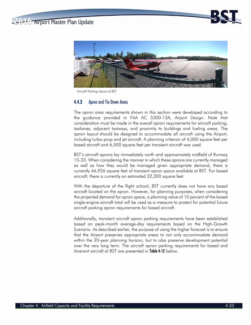
4.4.3 Apron and Tie Down Areas The apron area requirements shown in this section were developed according to the guidance provided in FAA AC 5300-13A, Airport Design. Note that consideration must be made in the overall apron requirements for aircraft parking, taxilanes, adjacent taxiways, and proximity to buildings and fueling areas. The apron layout should be designed to accommodate all aircraft using the Airport, including turbo-prop and jet aircraft. A planning criterion of 4,000 square feet per based aircraft and 6,500 square feet per transient aircraft was used. BST’s aircraft aprons lay immediately north and approximately midfield of Runway 15-33. When considering the manner in which these aprons are currently managed as well as how they would be managed given appropriate demand, there is currently 46,926 square feet of transient apron space available at BST. For based aircraft, there is currently an estimated 32,300 square feet. With the departure of the flight school, BST currently does not have any based aircraft located on the apron. However, for planning purposes, when considering the projected demand for apron space, a planning value of 10 percent of the based single-engine aircraft total will be used as a measure to protect for potential future aircraft parking apron requirements for based aircraft. Additionally, transient aircraft apron parking requirements have been established based on peak-month average-day requirements based on the High-Growth Scenario. As described earlier, the purpose of using the higher forecast is to ensure that the Airport preserves appropriate areas to not only accommodate demand within the 20-year planning horizon, but to also preserve development potential over the very long term. The aircraft apron parking requirements for based and itinerant aircraft at BST are presented in Table 4-12 below.
Aircraft Parking Apron at BST
AIRPORT MASTER PLAN UPDATE 2014
4-34 Chapter 4: Airfield Capacity and Facility Requirements
Table 4-12: BST Aircraft Apron Requirements
2014 2019 2024 2034 Based Aircraft Requiring Apron 2 2 2 2 Based Aircraft Apron Demand (SF) 8,000 8,000 8,000 8,000 Based Aircraft Apron Available (SF) 32,300 32,300 32,300 32,300 SURPLUS/DEFICIENCY (SF) 24,300 24,300 24,300 24,300 Transient Aircraft Requiring Apron 2 2 3 4 Transient Apron Demand (SF) 13,000 13,000 19,500 26,000 Transient Apron Available (SF) 46,926 46,926 46,926 46,926
SURPLUS/DEFICIENCY (SF) 33,926 33,926 27,426 20,926
Source: Airport Solutions Group.
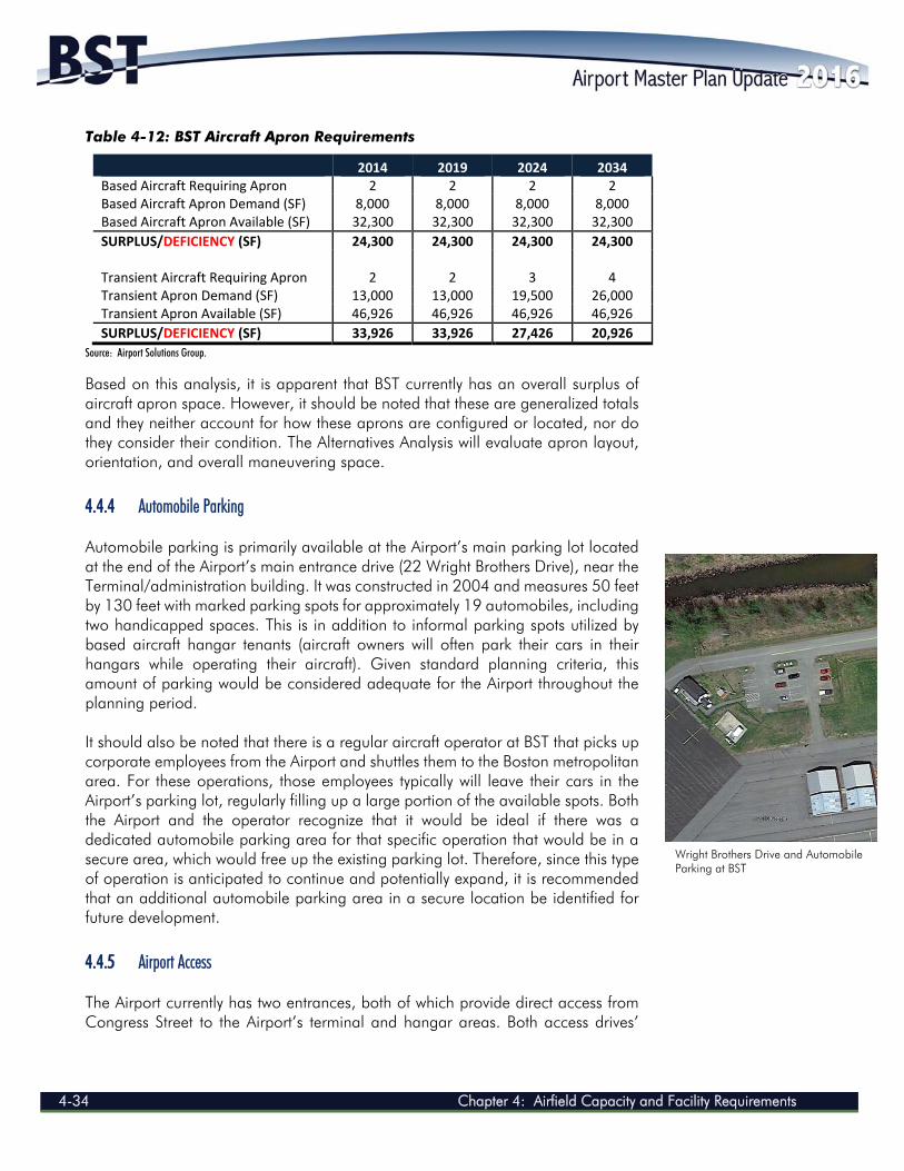
Based on this analysis, it is apparent that BST currently has an overall surplus of aircraft apron space. However, it should be noted that these are generalized totals and they neither account for how these aprons are configured or located, nor do they consider their condition. The Alternatives Analysis will evaluate apron layout, orientation, and overall maneuvering space. 4.4.4 Automobile Parking Automobile parking is primarily available at the Airport’s main parking lot located at the end of the Airport’s main entrance drive (22 Wright Brothers Drive), near the Terminal/administration building. It was constructed in 2004 and measures 50 feet by 130 feet with marked parking spots for approximately 19 automobiles, including two handicapped spaces. This is in addition to informal parking spots utilized by based aircraft hangar tenants (aircraft owners will often park their cars in their hangars while operating their aircraft). Given standard planning criteria, this amount of parking would be considered adequate for the Airport throughout the planning period. It should also be noted that there is a regular aircraft operator at BST that picks up corporate employees from the Airport and shuttles them to the Boston metropolitan area. For these operations, those employees typically will leave their cars in the Airport’s parking lot, regularly filling up a large portion of the available spots. Both the Airport and the operator recognize that it would be ideal if there was a dedicated automobile parking area for that specific operation that would be in a secure area, which would free up the existing parking lot. Therefore, since this type of operation is anticipated to continue and potentially expand, it is recommended that an additional automobile parking area in a secure location be identified for future development. 4.4.5 Airport Access The Airport currently has two entrances, both of which provide direct access from Congress Street to the Airport’s terminal and hangar areas. Both access drives’
Wright Brothers Drive and Automobile Parking at BST
Chapter 4: Airfield Capacity and Facility Requirements 4-35
pavements are considered to be in good condition. As such, vehicular landside access to BST is considered to be adequate throughout the planning period. 4.5 AIRPORT SUPPORT FACILITIES Current conditions at the Airport as well as possible future developments may impact aviation support facilities. Potential improvements necessary to meet deficiencies or address future needs for facilities are detailed below. 4.5.1 Fuel Storage Facilities Typically a primary revenue source for the operation and maintenance of any airport, aviation fuel (or rather, the current lack thereof) represents a significant factor affecting the development of the Airport. BST currently only has a 28-foot by 40-foot concrete pad located near the main ramp, which was the previous location of an above-ground 500-gallon 100 Low Lead aviation gasoline system. BST must plan for the reestablishment of 100 Low Lead fueling capabilities in order to meet the demand of its based customers, as well as to capitalize on a critical revenue stream to support the long-term maintenance and operation of the Airport. Additionally, it should be noted that turbine aircraft operations are projected to increase throughout the planning period; therefore, it is reasonable to assume that there will be an increasing level of demand for Jet-A fuel, which is also presently not available at BST. Recommendations for fuel storage at BST include the following:
Investigate potential locations for the installation of a new 5,000-gallon 100 Low Lead aviation gasoline fuel tank.
Explore the potential for establishing self-service fueling. Plan for the potential future installation of a Jet-A fuel tank.
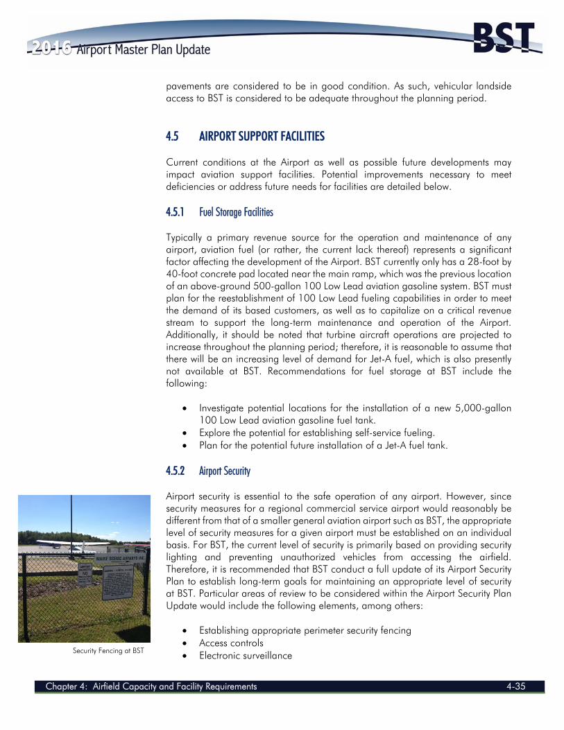
4.5.2 Airport Security Airport security is essential to the safe operation of any airport. However, since security measures for a regional commercial service airport would reasonably be different from that of a smaller general aviation airport such as BST, the appropriate level of security measures for a given airport must be established on an individual basis. For BST, the current level of security is primarily based on providing security lighting and preventing unauthorized vehicles from accessing the airfield. Therefore, it is recommended that BST conduct a full update of its Airport Security Plan to establish long-term goals for maintaining an appropriate level of security at BST. Particular areas of review to be considered within the Airport Security Plan Update would include the following elements, among others:
Establishing appropriate perimeter security fencing Access controls Electronic surveillance Security Fencing at BST
AIRPORT MASTER PLAN UPDATE 2014
4-36 Chapter 4: Airfield Capacity and Facility Requirements
Area lighting Security checks Perimeter roads
4.5.3 Airfield Maintenance Facilities All snow removal at the Airport is currently done by the City of Belfast's Public Works Department. All grass cutting at the Airport is currently done either by the City of Belfast's Public Works Department, the City of Belfast's Parks and Recreation Department, or by Rockport, Maine-based Aldermere Farm; the latter hays the large grassy expanses parallel to Runway 15-33. Because these activities are carried out by non-Airport entities, the Airport currently has no need for the previously-mentioned airfield maintenance storage shed, and instead allows it to be used for storage by the City of Belfast's Parks and Recreation Department. Until the City chooses to allocate resources to the Airport so that it may conduct its own maintenance activities, there exists no need for additional airfield maintenance facilities. 4.5.4 Aircraft Rescue and Firefighting The Airport does not have any Airport Rescue and Firefighting (ARFF) equipment. Since BST does not support Federal Aviation Regulations Part 139 air carrier operations, it is not required to have dedicated equipment or facilities. Emergency response services are provided by the Belfast Fire Department, which has a fire station at 273 Main Street, located 1.8 miles from the Airport. 4.6 MAINE AVIATION SYSTEMS PLAN UPDATE RECOMMENDATIONS In 2006, the Maine Department of Transportation Airports and Aviation Division completed the Maine Aviation Systems Plan Update (MASPU), which examined Maine's airports on a macro level and provided a general assessment of aviation needs within the State. Identified and adopted for use in this plan was a series of seven goals and associated system performance measures, which were the following:
To promote an airport system that improves Maine's quality of life by supporting health, welfare, and safety-related services and activities (Quality of Life system performance measure).
To have an airport system that adequately serves current and forecast demand (Capacity system performance measure).
To encourage and recognize system airports that support aviation programs and outreach opportunities in Maine (Aviation Outreach system performance measure).
To provide for a safe airport system, as measured by compliance with applicable FAA standards (Safety/Standards system performance measure).
Chapter 4: Airfield Capacity and Facility Requirements 4-37
To advance a system of airports that is supportive of Maine's economy, ensuring that the airport system is matched to Maine's socioeconomic and demographic characteristics (Economic Support system performance measure).
To protect and support an airport system that maintains the flexibility to respond to changes in future needs in Maine, while considering the environment (Flexibility system performance measure).
To provide an airport system that is easily accessible from both the ground and the air (Accessibility system performance measure).
Using these goals and system performance measures, the MASPU assigned each of the 36 airports that were included in the plan to one of four levels; these were based on the role that each airport plays in meeting the State’s aviation needs. As a Level III airport, BST serves a primary role in the local economy and is focused on supporting a variety of types of general aviation activities such as business, emergency service, recreational, and personal. The MASPU identified facility and service objectives for airports within each of the system levels, and then ultimately developed a series of recommended actions for each individual airport, both along the aforementioned system performance measures as well as facility and service objectives. The following is a listing of the MASPU-recommended actions for BST: Quality of Life System Performance Measure
Install Automated Weather Observing System Capacity System Performance Measure
Build hangars (as required) (Add) auto parking spaces (as required)
Outreach System Performance Measure
Develop public outreach program Promote Airport usage to new businesses Form partnership with chamber of commerce to promote Airport Educate the community on benefits to gain additional support and maintain
Airport-friendly community Work with local chamber of commerce to provide shuttle into town Develop a good neighbor program Increase student pilot enrollment, identify service area Host and promote annual fly-in
Safety/Standards System Performance Measure
Develop Vegetation Management Plan Pavement maintenance to meet >70 Pavement Condition Index Develop operations manual/accident reporting procedures Develop Wildlife Management Plan Develop Airport Security Plan (fencing/gates/video/signage)
AIRPORT MASTER PLAN UPDATE 2014
4-38 Chapter 4: Airfield Capacity and Facility Requirements
Economic Support System Performance Measure Create development plan for land surrounding Airport Promote Airport usage to new businesses Develop industrial park - businesses that rely on general aviation Work with City to hire an economic development director Promote BST as a multi-modal area with Airport, rail, harbor Administer a freight survey to determine how Airport can support local air
cargo needs Flexibility System Performance Measure
Update Airport Master Plan or ALP Develop business/financial plan Report annual activity data to the Office of Passenger Transportation Build golf course near Airport to promote appropriate land use
Accessibility System Performance Measure
Make sure that Global Positioning System approach (is) in working order Extend runway to 5,000 feet Obtain air taxi service to Islesboro and scenic flights Provide scheduled commuter service Improve Airport entrance sign
Facility and Service Objectives – Airside Facilities
Taxiway length- (add) turnaround (Add) taxiway reflectors Make sure that Global Positioning System approach in working order Extend runway to 5,000 feet Add parallel taxiway Maintain turf runway and promote usage Install visual slope approach indicators or precision approach path
indicators Facility and Service Objectives – Landside Facilities
(Add) hangars–based aircraft spaces (Add) apron tie down spaces (Add) auto parking spaces Improve hangar taxiway and repave hangar apron
Facility and Service Objectives – Services (Add) full perimeter fencing Develop Airport Security Plan (fencing/gates/video/signage) Provide automated fuel Provide ground transportation Expand FBO Obtain full-time aircraft maintenance Add restaurant or ice cream shop Provide Jet-A fuel and auto fuel
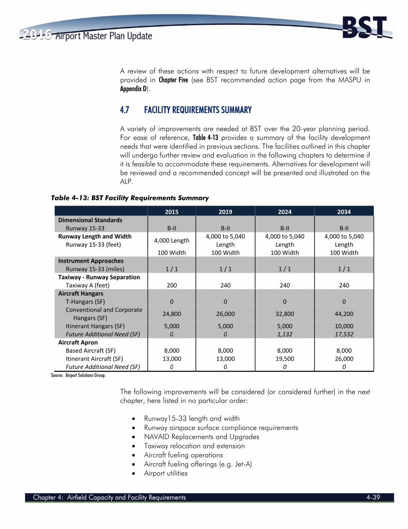
Chapter 4: Airfield Capacity and Facility Requirements 4-39
A review of these actions with respect to future development alternatives will be provided in Chapter Five (see BST recommended action page from the MASPU in Appendix D). 4.7 FACILITY REQUIREMENTS SUMMARY A variety of improvements are needed at BST over the 20-year planning period. For ease of reference, Table 4-13 provides a summary of the facility development needs that were identified in previous sections. The facilities outlined in this chapter will undergo further review and evaluation in the following chapters to determine if it is feasible to accommodate these requirements. Alternatives for development will be reviewed and a recommended concept will be presented and illustrated on the ALP.
Table 4-13: BST Facility Requirements Summary
2015 2019 2024 2034 Dimensional Standards Runway 15‐33 B‐II B‐II B‐II B‐II Runway Length and Width Runway 15‐33 (feet)
4,000 Length 4,000 to 5,040
Length 4,000 to 5,040
Length 4,000 to 5,040
Length 100 Width 100 Width 100 Width 100 Width Instrument Approaches Runway 15‐33 (miles) 1 / 1 1 / 1 1 / 1 1 / 1 Taxiway ‐ Runway Separation Taxiway A (feet) 200 240 240 240 Aircraft Hangars T‐Hangars (SF) 0 0 0 0 Conventional and Corporate Hangars (SF)
24,800 26,000 32,800 44,200
Itinerant Hangars (SF) 5,000 5,000 5,000 10,000 Future Additional Need (SF) 0 0 1,132 17,532 Aircraft Apron Based Aircraft (SF) 8,000 8,000 8,000 8,000 Itinerant Aircraft (SF) 13,000 13,000 19,500 26,000 Future Additional Need (SF) 0 0 0 0
Source: Airport Solutions Group.
The following improvements will be considered (or considered further) in the next chapter, here listed in no particular order:
Runway15-33 length and width Runway airspace surface compliance requirements NAVAID Replacements and Upgrades Taxiway relocation and extension Aircraft fueling operations Aircraft fueling offerings (e.g. Jet-A) Airport utilities
AIRPORT MASTER PLAN UPDATE 2014
4-40 Chapter 4: Airfield Capacity and Facility Requirements
Segregation of airport operations Hangar space location and use Airport security upgrades Airport services improvements Regulatory compliance Best management practices improvements On-Airport development Aprons Terminal/administration building Automobile parking Aircraft deicing