airfoil tubeaxial fans - my.amca.org · direct drive tubeaxial fans 1 jtantay 03.09.10 c us power...
TRANSCRIPT

joel ta
nta
y 10.2
6.0
9
Catalogue ATF, Dec 2017
C US
POWER VENTILATOR44DU
Evaluated by UL as per UL 705 (United State) and CSA Standard C22.2 No.113-M1984 (Canada).
Tubeaxial Fans are designed for use in low to medium pressure ducted applications.
They are generally used for removal of contaminated air or hot air found in industrial
applications; but can also be used to supply air through duct work for cooling or
pressurizing of the interior spaces ie. Elevator Shaft and Stairwells for Condominiums.
Tubeaxial fans are very versatile and compact for moving large volumes of air in duct
systems having relatively low pressure losses.
Belt DrivenModel
RBD
Direct DriveModel
RDD
AIRFOIL TUBEAXIAL FANS
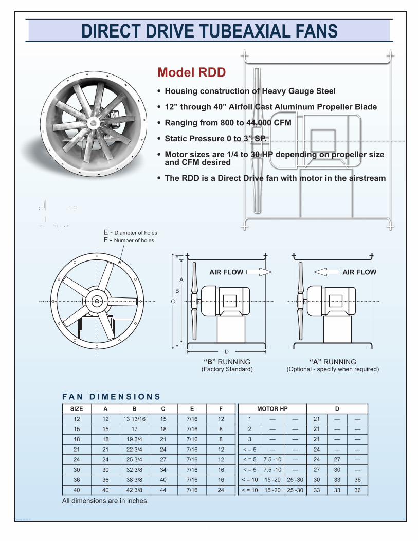
DIRECT DRIVE TUBEAXIAL FANS
1
jtantay 03.09.10
C US
POWER VENTILATOR44DU
E - Diameter of holes
F - Number of holes
Housing construction of Heavy Gauge Steel
12” through 40” Airfoil Cast Aluminum Propeller Blade
Ranging from 800 to 44,000 CFM
Static Pressure 0 to 3” SP.
Motor sizes are 1/4 to 30 HP depending on propeller size and CFM desired
The RDD is a Direct Drive fan with motor in the airstream
Model RDD
F A N D I M E N S I O N S
“B” RUNNING(Factory Standard)
AIR FLOW
“A” RUNNING(Optional - specify when required)
A
B
C
D
AIR FLOW
All dimensions are in inches.
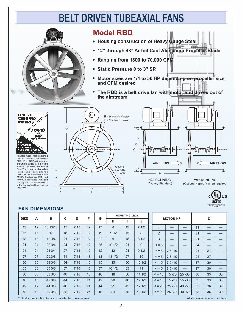
BELT DRIVEN TUBEAXIAL FANS
2
Housing construction of Heavy Gauge Steel
12” through 48” Airfoil Cast Aluminum Propeller Blade
Ranging from 1300 to 70,000 CFM
Static Pressure 0 to 3” SP.
Motor sizes are 1/4 to 50 HP depending on propeller size and CFM desired
The RBD is a belt drive fan with motor and drives out of the airstream
Model RBD
jtantay 03.09.10
FAN DIMENSIONS
* Custom mounting legs are available upon request
C US
POWER VENTILATOR44DU
AIR FLOW
“A” RUNNING(Optional - specify when required)
All dimensions are in inches.
“B” RUNNING(Factory Standard)
A
B
C
D
AIR FLOW
Reversomatic Manufacturing Limited certifies that Models RBD-12 to RBD-48 inclusive shown on pages 7, 8 & 9 are licensed to bear the AMCA Seal. The ratings are based on t e s t s a n d p r o c e d u r e s performed in accordance with AMCA Publication 211 and AMCA Publication 311 and comply with the requirements of the AMCA Certified Ratings Program.
E - Diameter of holes
F - Number of holes
J
G
I
H H
Optional Mounting
Legs

0” SP 1/8” SP 1 /4” SP 3/8” SP 1/2” SP 3/4” SP 1” SP 1-1/2 SP
CFM CFM CFM CFM CFM CFM CFM CFM
BELT DRIVE 150 mm HUB DIA. 5 BLADES 25° BLADE ANGLE
RBD-12”
0.25 HP 353 2371 1 294 1251 1167 1076 986 7 66
0.33 HP 471 2601 1 429 1382 1303 1224 1142 9 53 662
0.50 HP 707 2988 1632 1525 1482 1386 1292 987 8210.75 HP 1059 3420 1870 1820 1760 1690 1620 1 460 1200 460
1.00 HP 1413 3765 2057 2006 1949 1879 1812 1 657 1384 566
RBD-15”
0.50 HP 631 1860 2 258 2070 1850 1610 1215 250
0.75 HP 1032 2192 2 661 2500 2348 2145 1930 81 0 353
1.00 HP 1268 2348 2850 2710 2560 2390 2200 161 0 590
1.50 HP 1894 2685 3260 3200 3000 2876 2760 2 364 1190 432
2.00 HP 2528 2955 3587 3390 3280 3190 3080 2 790 2300 8 50
RBD-18”
0.75 HP 864 1951 3 613 3493 3256 3021 2769 2 230
1.00 HP 1153 2148 3978 3857 3641 3421 3197 2 699 1995
1.50 HP 1730 2459 4558 4445 4245 4038 3831 3 379 2690 878
2.00 HP 2307 2706 5018 4895 4713 4519 4313 3 880 3174 1 213
3.00 HP 3460 3097 5741 5599 5439 5251 5059 4 632 3875 1 600
RBD-21”
0.75 HP 800 1580 4 606 4422 4064 3698 3320 2 340
1.00 HP 1068 1739 5066 4895 4570 4231 3878 3 099
1.50 HP 1602 1991 5797 5642 5348 5044 4726 4 045 3065
2.00 HP 2136 2191 6384 6227 5952 5665 5371 4 729 3763 1 199
3.00 HP 3204 2508 7305 7125 6896 6619 6350 5 736 4721 1 854
RBD-24”
1.00 HP 987 1478 7 996 7636 7124 6624 5997 4 505
1.50 HP 1480 1691 9150 8839 8391 7977 7458 6 424 4924
2.00 HP 1973 1861 1 0071 9786 9375 9017 8524 7 655 6528
3.00 HP 2960 2132 1 1479 11227 10915 10603 10187 9 459 8524 3 742
5.00 HP 4933 2528 1 3664 13318 13059 12840 12494 1 1836 11098 5548
RBD-27”
1.00 HP 931 1365 9 738 9096 8264 7495 6516 5 148
1.50 HP 1396 1561 1 1170 10585 9848 9193 8424 6 648
2.00 HP 1861 1718 1 2285 11799 11071 10491 9788 8 409 7171
3.00 HP 2792 1969 1 4047 13654 12962 12451 11821 1 0743 9345 4409
5.00 HP 4654 2334 1 6650 16278 15690 15272 14704 1 3745 12590 5940
PERFORMANCE DATA OF TUBEAXIAL FANS
MOTORH.P.
Max. InputPower Watts
FAN RPM
7
NOTE: Performance certified is for installation type A; Free Inlet, Free Outlet. Performance ratings do not include the effects of appurtenances (accessories). Power (BHP) includes transmission losses. The sound ratings shown are loudness values in fan sones at 1.5 m (5 ft.) in a hemispherical free field calculated per AMCA International Standard 301. Values shown are for: Installation A: Free inlet hemispherical sone levels.

BELT DRIVE 150 mm HUB DIA. 5 BLADES 25° BLADE ANGLE
MOTOR Max. InputFAN RPM
0” SP 1/8” SP 1 /4” SP 3/8” SP 1/2” SP 3/4” SP 1” SP 1-1/2 SP 2 ” SP 2 -1/2” SP
HP Power Watts CFM CFM CFM CFM CFM CFM CFM CFM C FM CFM
RBD-30”1.00 HP 883 1148 1 1479 10556 9404 8366 7035
1.50 HP 1324 1313 13191 12332 11305 10408 9389 6872
2.00 HP 1765 1445 14500 13812 12767 11965 11052 9163
3.00 HP 2648 1655 16614 16081 15008 14299 13455 12027 10165
5.00 HP 4412 1963 19635 19238 18322 17704 16914 15654 14082 6333
7.50 HP 6619 2247 22455 22000 21440 20817 19990 18803 17440 8583
RBD-33”1.00 HP 841 990 1 3221 12016 10545 8467 7554
1.50 HP 1262 1133 15211 14078 12762 10969 10355 7096
2.00 HP 1682 1246 16714 15825 14462 12859 12316 9917
3.00 HP 2523 1428 19182 18508 17055 15637 15088 13310 10986
5.00 HP 4205 1693 22621 22198 20953 19718 19124 17562 15574 6725
7.50 HP 6308 1938 25870 25385 24519 23185 22602 21095 19288 9114
RBD-36”2.00 HP 1760 1045 17769 16390 15240 13964 12311 8783
3.00 HP 2640 1196 20278 19219 18073 16873 15531 13292 6733
5.00 HP 4400 1418 24093 23316 22176 21140 19793 18135 11399
7.50 HP 6600 1627 27506 26731 26731 24922 23581 22122 14465
10.0 HP 8800 1787 30317 29462 29462 27928 26517 25256 16798
NOTE: Performance certified is for installation type A; Free Inlet, Free Outlet. Performance ratings do not include the effects of appurtenances (accessories). Power (BHP) includes transmission losses. The sound ratings shown are loudness values in fan sones at 1.5 m (5 ft.) in a hemispherical free field calculated per AMCA International Standard 301. Values shown are for: Installation A: Free inlet hemispherical sone levels.
• Test Data
RBD12
RBD15
RBD18
RBD21
RBD24
RBD27
RBD30
RBD33
RBD36
0
10
20
30
40
50
60
0 5 10 15 20 25
CFM x 1000
SO
NE
S
SONES AT 0.00” STATIC PRESSURE
8
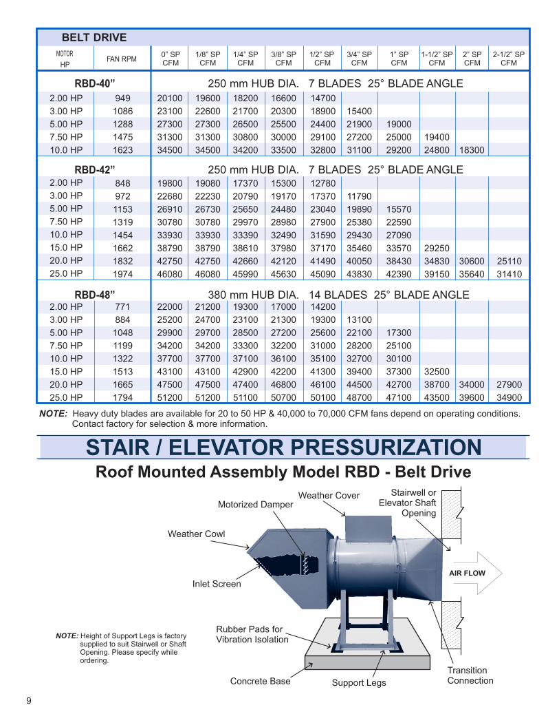
BELT DRIVE
FAN RPMMOTOR
HP
RBD-40”
RBD-42”
RBD-48”
0” SPCFM
1/8” SPCFM
1/4” SPCFM
3/8” SPCFM
1” SPCFM
/2” SPCFM
1 3/4” SPCFM
1-1/2” SPCFM
2” SPCFM
2-1/2” SPCFM
2.00 HP
3.00 HP
5.00 HP
7.50 HP
10.0 HP
949
1086
1288
1475
1623
20100
23100
27300
31300
34500
19600
22600
27300
31300
34500
18200
21700
26500
30800
34200
16600
20300
25500
30000
33500
14700
18900
24400
29100
32800
15400
21900
27200
31100
15570
22590
27090
33570
38430
42390
19400
24800 18300
2.00 HP
3.00 HP
5.00 HP
7.50 HP
10.0 HP
15.0 HP
20.0 HP
25.0 HP
848
972
1153
1319
1454
1662
1832
1974
19800
22680
26910
30780
33930
38790
42750
46080
19080
22230
26730
30780
33930
38790
42750
46080
17370
20790
25650
29970
33390
38610
42660
45990
15300
19170
24480
28980
32490
37980
42120
45630
12780
17370
23040
27900
31590
37170
41490
45090
11790
19890
25380
29430
35460
40050
43830
29250
34830
39150
19000
25000
29200
30600
35640
25110
31410
250 mm HUB DIA. 7 BLADES 25° BLADE ANGLE
250 mm HUB DIA. 7 BLADES 25° BLADE ANGLE
380 mm HUB DIA. 14 BLADES 25° BLADE ANGLE 2.00 HP
3.00 HP
5.00 HP
7.50 HP
10.0 HP
15.0 HP
20.0 HP
25.0 HP
771
884
1048
1199
1322
1513
1665
1794
22000
25200
29900
34200
37700
43100
47500
51200
21200
24700
29700
34200
37700
43100
47500
51200
19300
23100
28500
33300
37100
42900
47400
51100
17000
21300
27200
32200
36100
42200
46800
50700
14200
19300
25600
31000
35100
41300
46100
50100
13100
22100
28200
32700
39400
44500
48700
17300
25100
30100
37300
42700
47100
32500
38700
43500
34000
39600
27900
34900
NOTE: Height of Support Legs is factory supplied to suit Stairwell or Shaft Opening. Please specify while ordering.
Weather CoverMotorized Damper
Weather Cowl
Inlet Screen
Concrete Base
Stairwell or Elevator Shaft
Opening
Rubber Pads for Vibration Isolation
Support Legs
Transition Connection
Roof Mounted Assembly Model RBD - Belt Drive
STAIR / ELEVATOR PRESSURIZATION
9
NOTE: Heavy duty blades are available for 20 to 50 HP & 40,000 to 70,000 CFM fans depend on operating conditions. Contact factory for selection & more information.
AIR FLOW

INSTALLATIONReversomatic RDD and RBD duct fans may be mountedin any position using several different methods, mountingbrackets for ceiling suspension and support legs for floor mounting. Angle supports for rod hangers. For convenience in wiring & service, the motor should be readily accessible. On direct drive units, access through adjacent duct work is recommended. On belt drive units, the motor position must
be considered with regard to service and adjacent objects such as wall and ceiling. Access door is provided. The duct fan has flanged ends on the steel housing forconvenience mounting directly in the duct system. Flexible connections or transition pieces may be utilized to reduce noise transmission, simplify duct attachment and provide access to interior of fan.
RBD TYPICAL SPECIFICATIONAll belt-drive tube axial fans supply and/or exhaust aremodel RBD as manufactured by Reversomatic. Propeller construction consists of extruded aluminum propeller blades mounted in cast aluminum hub.The blade pitch is pre-set at the factory to match design conditions and locked into place by means of a self-locking pin. All propellers are statically and dynamically balanced for vibration-free operation. All fans have a heavy gauge steel housing and power assembly. All bearings are grease
lubricated ball bearing pillow block type with a minimum average life of 100,000 hours. All units have external grease fittings for ease in lubricating. Oil resistant nonstatic belts are provided. All fans bear the AMCA seal for sound and air performance. All steel sheet metal parts are cleaned, conditioned and painted with enamel paint finish prior to assembly. A final coat of gray enamel is applied to all exterior surfaces after assembly.
MAINTENANCETube axial fans should be cleaned as necessary toremove accumulated dust, dirt and other foreign matter which my collect on the blades or interior surfaces. Belt drive, belt(s) should be inspected and tension adjusted. Check belt(s) for proper alignment. On all belt drive models fan bearings are factory lubricated for extended service.External relubrication fan bearing fittings are standard
with belt drive models. Pillow-block ball bearings should be lubricated annually or more frequently, depending upon conditions and operating cycle. For lubrication of electric motor, see instructions supplied by motor manufacturer. Always check blade clearance and check direction of rotation with arrow on housing before operating.
W A R R A N T Y
REVERSOMATIC MANUFACTURING LIMITED WARRANTS IT WILL PROVIDE A REPLACEMENTPART OF ITS FANS FOUND TO BE DEFECTIVE IN MATERIAL OR WORKMANSHIP FOR A PERIODOF ONE YEAR FROM DATE OF PURCHASE FOR FIRST USER, F.O.B. OUR PLANT.
NOTE: THIS WARRANTY DOES NOT APPLY TO LABOR COSTS INVOLVED IN REPLACEMENT OR REINSTALLATION, DIAGNOSTIC SERVICE, CLEANING AND ADJUSTMENT OR TRANSPORTATION. FURTHERMORE WARRANTY IS ONLY APPLICABLE WHEN REVERSOMATIC REPLACEMENT PARTS AND ACCESSORIES ARE USED.
APPROXIMATE SHIPPING WEIGHT (LESS MOTOR) LBS
10
30
36
40
42
48
209
396
440
286
418
484
528
616
FANSIZE RDD RBD
12
15
18
21
24
66
110
141
158
176
79
121
150
198
238
FANSIZE RDD RBD

ACCESSORIES - (Optional)
ALUMINUM DIE CAST PROPELLER
790 Rowntree Dairy Road, Woodbridge ON, Canada L4L 5V3 Tel: 905-851-6701 Fax: 905-851-8376 [email protected]
w w w . r e v e r s o m a t i c . c o m
REVERSOMATIC
ALSO AVAILABLE: Floor Mounting Feet, and Disconnect Switch.
WEATHER COVERComplete enclosure weather covers are available on all RBD fans. The cover provides weather protection for the motor and the drive when the fan is used in outside applications.
BELT GUARDBelt Guard is available for all RBD fans to prevent accidental contact with the drive. Expanded metal is used to cover the front of the guard to allow visual inspection of the drive without removal of the guard.
INSPECTION DOORProvides easy access to the bearings.
INLET BELLSpun aluminum inlet bell available for installation on site
SUPPORT FRAME / CEILING BRACKET
Standard Duty Blade(800 to 40,000 CFM)
Heavy Duty Blade(40,000 to 70,000 CFM)
The RBD/RDD aluminum die cast propeller has been designed for
use where high static pressure are required. It is constructed of multiple
blades 5, 7, 8, 9,10, 14 & 16 blades. The pitch setting of the blades is
done at the factory & the blades are locked into place by means of a
self-locking pin. Both units come in a variety of pitches (5° to 45°) to
provide a wider performance range. Due to the airfoil blade design the
propeller has a non-overloading characteristic such as found in a
centrifugal type wheel. The propeller is available in sizes 12” trough 48”
for belt drive RBD and 12” to 40” for direct drive RDD. Both types cover
the range of 0” to 3” static pressure. Each propeller is statically and
dynamically balanced for vibration free operation. It is designed for
(temperature range) - 40° to 302°F (-40° to 150°C).
NOTE: For 20 HP & Up and 1” S.P. & higher,
use heavy duty blades.
SCREEN