airframe structural materials for drone applications · 2018-11-09 · weight of the airframe...
TRANSCRIPT

•
<0
CO
ARPA ORDER NO.: 189-1
R-581/4-ARPA July 1971
Airframe Structural Materials for Drone Applications
Donald F. Adams D DC ?MJM
FEB I5 1972
B
A Report prepared for
ADVANCED RESEARCH PROJECTS AGENCY RcprMhicwJ by
NATIONAL TECHNICAL INFORMATION SERVICE
Springflsld, V>. 21151
Rand SANTA MOMCACA. 90406
iN 51 '
-vll-
CONTENTS
PREFACE ±i±
SUMMARY v
TABLES lx
Section I. INTRODUCTION 1
II. CANDIDATE MATERIALS 3
III. APPLICABILITY TO SPECIFIC MISSIONS 8
IV. TYPICAL AIRFRAME-MATERIAL COMBINATIONS 15
Aluminum 15 Fiberglass 16 Fiberglass with Paper Honeycomb Core 16 Cast and Molded Plastics 17 Paper and Foam 17 Wood 17 Sall-Wlng Design 18 Graphlte-Fllament/Epoxy Composites 18 Titanium Alloys 18 Other Possibilities 19
V. AIRFRAME STRUCTURAL WEIGHT COMPARISONS FOR VARIOUS MATERIAL COMBINATIONS 20
Subsonic Cruise Vehicles 20 Supersonic Cruise Vehicles 31 Mach 2.3 32 Mach 3.0 35 Mach 3.0 37 Summary 38
REFERENCES 41
DOCUMENT CONTROL DATA
I OP;r,i:MriNG ACTIVITY
The Rand Corporation
2a. REPORT SECURITY CLASSIFICATION
UNCLASSIFIED 2b. GROUP
PORT TI'lE
AIRITVME STRUCTITRAL MATERIALS FOP. DRÖffi APPLICATIONS
4. AUTHO'IS) (latt nomo, finl nome. iniliol)
Adsms, Donald F.
5 RErORT DATE
Jolv 1971
6a. TOTAL NO. OF PAGES
50
6b. NO. OF REFS.
7
7.' CONTRACT OS GRANT NO.
DAHC15 67 C 0141 8. ORIGINATOR S REPORT NO.
R-581/4-APPA
I, AVAIIABILITY/LIW.ITATION NOTICES
DDC-A
-^ /■
^
9b. SPONSORING AGENCY
Mvanced Research Projects Aqencv*
^'^RVCT
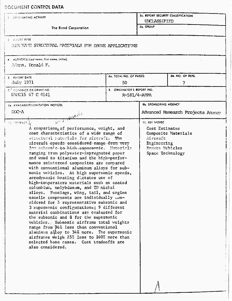
A comparison^of performance, weight, and cost characteristics of a wide range of structural materials for aircraft. The aircrsft spoedc conoidorcd range frcrr. very 1nv suhsonT'c to hial» ■.sunareoni-c. !fitßrir,ls ranging from polyester-inpregnated paper and wood to titanium and the high-perfor- mance reintorced composites are compared with conventional aluminum alJ.oys for sub- sonic vehicles. At high supersonic speeds, aerodynamic heating dictates use of high-tciupcrature materials such as coated colurabiun, molybdenum, and TD nickel alloys. Fuselage, wing, tail, and engine nacelle components are individually v,on- sidcred for 5 representative subsonic and 3 supersonic configurations; 9 different material combinations arc evaluated for the subsonic and 8 for the supersonic vehicles. Subsonic airframe total weights range from 36% less than conventional aluminum al/loy to 34% more. The supersonic airfranes weigh 25% less to 160% more than selected base cases. Cost tradeoffs are also considered.
11, KEY V/ORDS
Cost Estimates Composite Materials Aircraft 1Pn(»4nnA«>4M»
Remote Vehicles Space Technology

ARPA ORDER NO.: 189-1
R-581/4-ARPA July 1971
Airframe Structural Materials for Drone Applications
Donald F. Adams
A Report prepared for
ADVANCED RESEARCH PROJECTS AGENCY
Rand SANTA MONtCA,CA 90406
APPROVED FOR PUBLIC RELEASE; DISTRIBUTION UNLIMITED

Bibliographies of Selected Rand Publications
Rand maintains a number of special subject bibliographita containing abstracts of Rand publications in fields of wide current interest. The following bibliographies are available upon request:
Aerodynamics • i4ms Control • Civil Defense Communication Satellites • Communication Systems
Communist China • Computer Simulation • Computing Technology Decisionmaking • Game Theory • Maintenance
Middle East • Policy Sciences • Program Budgeting SIMSCRIPT and Iti; Applications • Southeast Asia
Space Technology and Planning • Statistics • Systems Analysis USSR/East Europe • Weapon Systems Acquisition
Weather Forecasting and Control
To obtain copies of these bibliographies, and to receive information on how to obtain copies of individual publications, write to: Communications Department, Rand, 1700 Main Street, Santa Monica, California 90406.
Published by The Rand Corporation

,
-iii-
PREFACE
This Investigation Is part of a larger project sponsored by the
Advanced Research Projects Agency on costs and performances of military
drone vehicles. The work reported here on structural materials Is
unclassified and has a much broader application; therefore, It Is
also being published separately to make It readily available.
-V-
SUMMARY
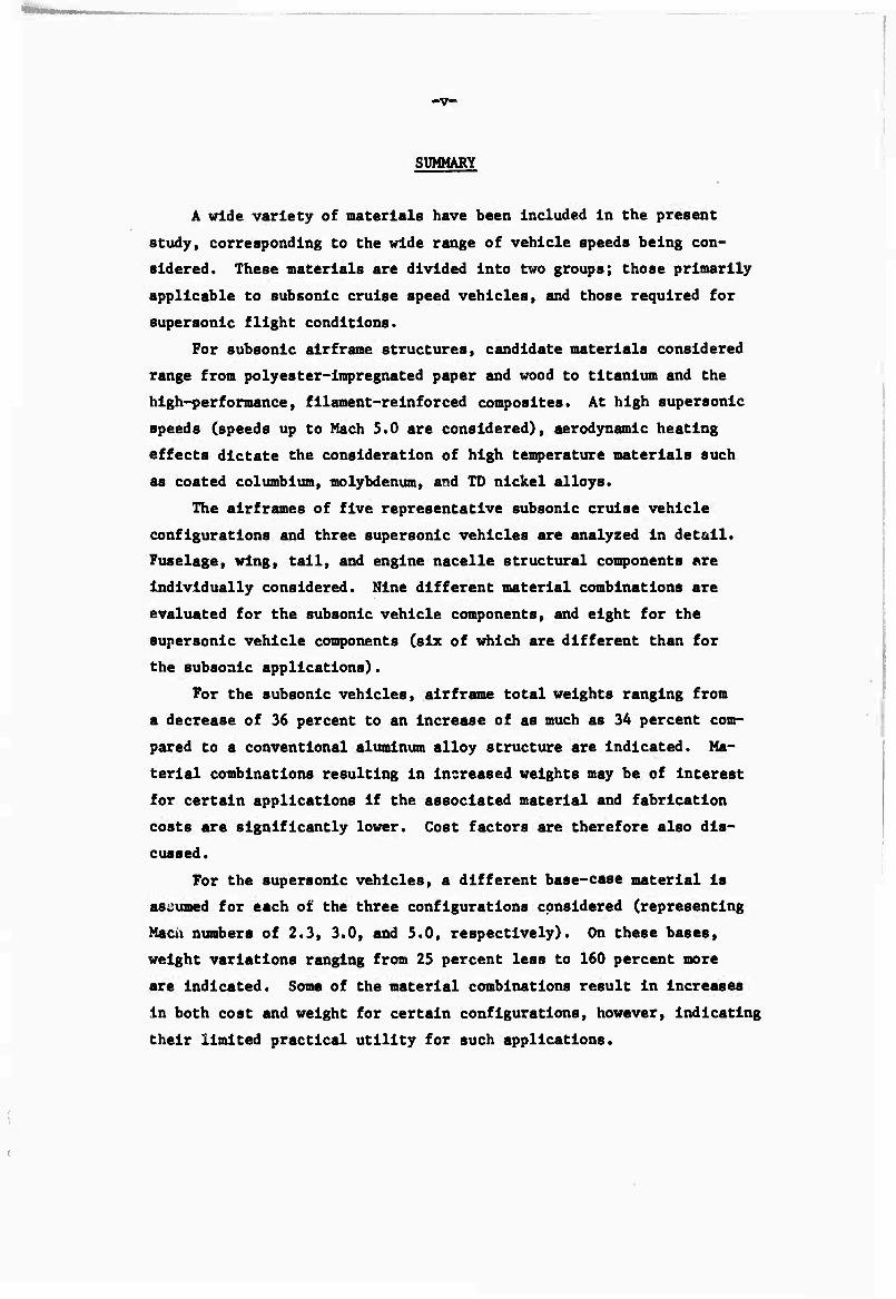
A wide variety of materials have been Included in the present
study, corresponding to the wide range of vehicle speeds being con-
sidered. These materials are divided Into two groups; those primarily
applicable to subsonic cruise speed vehicles, and those required for
supersonic flight conditions.
For subsonic airframe structures, candidate materials considered
range from polyester-Impregnated paper and wood to titanium and the
high-performance, filament-reinforced composites. At high supersonic
speeds (speeds up to Mach 5.0 are considered), aerodynamic heating
effects dictate the consideration of high temperature materials such
as coated columblum, molybdenum, and TD nickel alloys.
The alrframes of five representative subsonic cruise vehicle
configurations and three supersonic vehicles are analyzed In detail.
Fuselage, wing, tall, and engine nacelle structural components are
individually considered. Nine different material combinations are
evaluated for the subsonic vehicle components, and eight for the
supersonic vehicle components (six of which are different than for
the subsonic applications).
For the subsonic vehicles, airframe total weights ranging from
a decrease of 36 percent to an Increase of as much as 34 percent com-
pared to a conventional aluminum alloy structure are indicated. Ma-
terial combinations resulting in increased weights may be of interest
for certain applications if the associated material and fabrication
costs are significantly lower. Cost factors are therefore also dis-
cussed.
For the supersonic vehicles, a different base-case material is
assumed for each of the three configurations considered (representing
Mach numbers of 2.3, 3.0, and 5.0, respectively). On these bases,
weight variations ranging from 25 percent less to 160 percent more
are indicated. Some of the material combinations result in increases
in both cost and weight for certain configurations, however, indicating
their limited practical utility for such applications.

-vl-
The performance, weight, and cost data contained In this report
will be directly applicable to other drone, telecraft, aircraft, and
spacecraft structural material selection studies as well.
•
•
■•

-ix-
TABLES
1 Basic Material Characteristics 4
2 Relative Rankings of Characteristic Material Properties 7
3 Materials Applicability for Specific Mission Requirements ... 9
A Materials Applicability: Mach 0.15 to Mach 0.30 Cruise Vehicle, Moderate and Severe Loads 11
5 Materials Applicability: Mach 0.5 to Mach 0.9 Cruise Vehicle, Moderate and Severe Loads 12
6 Materials Applicability: Mach 2.3 Cruise Vehicle, Moderate and Severe Loads 13
7 Materials Applicability: Mach 3.0 Cruise Vehicle, Moderate and Severe Loads 14
8 Characteristics of Representative Subsonic Cruise Vehicles Selected for Analysis 21
9 Structural Weights for Subsonic Cruise Vehicles: Configuration 1 23
10 Structural Weights for Subsonic Cruise Vehlclos: Configuration 2 24
11 Structural Weights for Subsonic Cruise Vehicles: Configuration 3 25
12 Structural Weights for Subsonic Cruise Vehicles: Configuration 4 26
13 Structural Weights for Subsonic Cruise Vehicles: Configuration 5 -. 27
14 Weight ' eduction Factors for Various Material Coir InatIons for Subsonic Drones 29
15 Characteristics of Representative Supersonic Cruise Vehicles Selected for Analysis 31
16 Representative Aerodynamic Heating Temperature Ranges 33
17 Relative Structural Weights and Finished-Part Costs for Supersonic Cruise Vehicles 39
-1-
I. INTRODUCTION
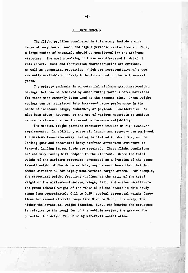
The flight profiles considered In this study Include a wide
range of very low subsonic and high supersonic cruise speeds. Thus,
a large number of materials should be considered for the airframe
structure. The most promising of these are discussed in detail in
this report. Cost and fabrication characteristics are examined,
as well as structural properties, which are representative of those
currently available or likely to be Introduced in the next several
years.
The primary emphasis is on potential airframe structural-weight
savings that can be achieved by substituting various other materials
for those most commonly being used at the present time. These weight
savings can be translated into increased drone performance in the
sense of Increased range, endurance, or payload. Consideration has
also been given, however, to the use of various materials to achieve
reduced airframe cost or increased performance reliability.
The mission flight profiles considered include no high maneuver
requirements. In addition, where air launch and recovery are employed,
the maximum launch/recovery loading is limited to about 3 g, and no
landing gear and associated heavy airframe attachment structure to
transmit landing impact loads are required. These flight conditions
are not ve;y taxing with respect to the airframe. Hence the total
weight of the airframe structure, expressed as a fraction of the gross
takeoff weight of the drone vehicle, may be much lower than that for
manned aircraft or for highly maneuverable target drones. For example,
the structural weight fractions (defined as the ratio of the total
weight of the airframe—fuselage, wings, tail, and engine nacelle—to
the gross takeoff weight of the vehicle) of the drones in this study
range from approximately 0.11 to 0.29; typical structural weight frac-
tions for manned aircraft range from 0.25 to 0.35. Obviously, the
higher the structural weight fraction, i.e., the heavier the structure
is relative to the remainder of the vehicle system, the greater the
potential for weight reduction by materials substitution.
T
-2-
For several of the drones to be analyzed in detail, the weight
of the payload Is greater than that of the entire alrframe. Hence,
one's first Impression might well be that a small reduction In total
alrframe weight Is of little significance. However, as the mission
flight profile begins to approach the limits of the performance capa-
bility for a «specific drone, e.g., very high cruise altitudes or
speeds, and under severe launch and/or recovery conditions, the per-
formance efficiency of the alrframe structure becomes much more im-
portant.

-3-
II. CANDIDATE MATERIALS
Fifteen different materials, Including the aluminum alloys cur-
rently In general use, have been considered for subsonic drones.
These materials are listed In Table 1. Additional materials, having
better elevated-temperature properties, will be Introduced later In
the discussion of cases where aerodynamic heating effects associated
with supersonic flight become a dominant factor. Some of the candi-
date materials have particularly high specific strength characteris-
tics (strength divided by density); these materials are most advan-
tageously used In strength-critical components of the structure, e.g.,
fuselage frames and secondary structure. Other materials have ex-
cellent specific stiffness properties (stiffness divided by density)
and are superior In stiffness-critical components, e.g., wing and
tall assemblies, particularly In the form of highly stressed skins.
Thus, the potential weight savings of a given material, relative to
aluminum, depend upon the particular application. Some materials, M
e.g., unrelnforced ABS plastics, nay actually result In a weight
penalty, as Indicated by the negative numbers In parentheses In
Table 1. However, a lower finished part cost may be possible with
such materials because of low basic material cost and/or lower fab-
rication costs. Thus, for certain cost-critical applications, a
material that offers no weight savings may still be an attractive
candidate.
Materials 7 through 11 are representative contlnuous-fllament-
relnforced matrix materials. Epoxy Is high-polymer plastic with
good mechanical properties up to about 250*F. The polylnlde plastic
matrix of Material 10 has comparable mechanical properties up to
temperatures as high as 600*F but Is presently slightly more expen-
sive and difficult to work with than epoxy.
Two types of glass filaments, conmonly designated as E glass and
S glass, are In general use. The S glass Is a higher-strength and,
Secondary structure Includes such Items as equipment mounting shelves, brackets, and similar non-flight-critical components.
** A thermoplastic polymer formed by copolymerlzing aerylonltrlie,
butadiene, and styrene monomers.

-4-
3
U H
i
1 «J
h" i i ^ 1 o IH -o w E m
««»So o o x; o c u t i-t (N 00 o\ O >H IN O t-t O ON r^ t-t XO
•H T^ CD U -H • • • • • ' • « * • • • • * * 1 <J a -H B u 3 >^ c w 3 »-
1 n-l IN O O . f i (N IN (N o o o •H O
! U, « < a. I a«
1 V a wi s-*
r-t « 3 *i •H eg o eo ^ e Id -H HJ C O «1 O 1- «H « u in in m »M »n O m m m m o m m m o
•H 0) O. t- Xi U CM tN IM IN tH r-t <-l IN O. *J (0 3 3 4)
E " * *J
:' 0) o o o o o o 1 w u m in • o CO /-v • • in r^ o »o o o o o O O VO • Q ? ^ ^ ^ r-H Psl tH »o o O O O o o O "^ ** IN o h «9 « iH I i i . . • • • • • » • • i • M « -H *^ o o o o ■* IN «.-t © o O o o o m m 0 fQ U vy in mm sr -a- o o SO ■ O 41 v-' • • • CN tN CO »3- t
L ^ o o fn 0
a ^^ ^ 01 60 U u u c e id 3 • •H 0) •O *J o o m o o o m m m m m m o < > Ü C O m .H CM IN CI i-( CM fN iH iH I IN . id VJ O 3 I ss M 01 O M
p. at u 1 4J ^^ «n w
ll h « c o * -a 1-) o o o o m m m o O O O vO o o a, 1 60-H
C a) r-( CO M
1 rn m sr «» en IN tn
I i rH m
•! »3 "H H 3
K 9 01 t o « 60 9 M Wi id
P. 0» I-l • o m oo o O o m o O m r^ o IN m (X> 01 iH iH CM rH rH (N IN m m CN n 1-1 < 1 1 1 l
0) 1 u 4-1 h •H C 0)
u « 0) p. 0) 0) o § id o *
11 60 4J o) *-» a a-H CD a C to 4J 1-) 6 rH U T3 >s •H 0) >, •H a» m a •H •O CD O H TS >^ X ?>-. m 4J o o
X O T4 P. U-l r 0) id o
3 r^ O | 1 «o a-S ^
•H •H OP. o p. u B oi 01 •a 1 id U P. 0> p. B o o -a V ß ß «-• 0) |
■H ß •^^ 0) O P. U -H ■ri •H 60V3 Id <-> M a -H «mm
ric/
xy c
com
oxy
lyim
Ä IFS«3 at 0) ►,^-' ►< « en a ß *-• o o id id id HP. ID
Id B T3 3 •H
S iH B» rH iH iH H B U rH >, i-< 60 60 ,a o x p. o
id a x oi a 60 ■H 0) O id -H
id o ^^ id t3 1 O -H iH U •-, ■HO) UM «4-1 0) o ^*^ U 01 M M tl •P id
3 id o) 3 T) -a >^ P. 0) 0) O U 0) O Id »- id
K m «i oi w iJ Wl *J >4-l > 0 «-I 3 C H <H f i CD 0) ^> -H -H 1 O CD ß ^ iJ •H IH ß c a P. td <d c £ £ ß <4-l 0) M TJ ß u B 01 -H Id P. P.
9 oi a <-> o o ^-t •H o P. a o ß ►» i) "O •H O 60 60 h Id Id u ■rt rH H O iH H
< WJ 0) H 6 ö o u u
UJ W CQ Ü U o 0) O C O
M (^ Ö S 0 ^ CD K
M
* 1 m IH «M m ^ m vO r^ 00 ov O .H IN m ■*
1 1 M rH i-( <H r-t
•a u 0)
TJ •rt m c o o 01 h (d
x:
ß o m u 0) a 3 m I
60
O
U 01 4J id e
m m o P.
u 4)
*J o

—5—
In particular, a hlgher-stlffness filament (about 12.4 x 10 pal ver-
sus about 10.5 x 10 psi for E glass). However, It Is also about
twice as expensive as E glass, although both are moderately low-cost
(see Table 1).
The polyester plastic of Materials 4 and 12 has a lower cost but
also poorer mechanical properties than epoxy, while Its environmental
resistance Is equally good. Thus Material 4, Incorporating the low-
cost E glass filament and the low-cost polyester matrix. Is a less
expensive (but lower performance) material than either Material 6 or
5, Material 12, polyester-impregnated paper, is even less expensive
because of the low cost of paper relative to that of glass filaments.
The chopped-glass-filament-relnforced plastic composites, Materials
4 and 5, are easily molded and result in low-cost finished parts. The
same is true of the unrelnforced ABS plastic, although its mechanical
properties are considerably poorer than those of the reinforced mate-
rials (which shows up clearly in the weight-savings comparisons).
The fabric-reinforced plastic composites, exemplified by Material
6, are stronger and stlfif (particularly in the directions of the
weave) than the chopped-filament-relnforced plastics but are not as
readily fabricated. Correspondingly, they are easier to fabricate
than the unidirectionally reinforced (nonwoven) composites but are
not as strong or stiff.
Use of molding materials (4, 5, and 13) and tape-layup materials
(7 through 10) results in very low scrap losses during manufacture.
Scrap loss is a factor to consider in comparing their actual costs
relative to those of materials utilized in other forms such as sheet,
plate, and machined parts.
The metal matrix composite. Material 11, is included as an example
of a very promising future airframe material. Continuous boron- or
graphite-filament-reinforced aluminum Is listed, since the development
of aluminum matrix composites is presently the most advanced. However,
other metals such as titanium and nickel are also very promising matrix
materials and are being investigated at the present time. The very
high current basic material cost and finished-part cost are primarily
due to the limited quantities being produced and the high development

-6-
costs still being Included In cost quotations. These costs should de-
crease rapidly In the next several years.
Nylon fabric Is not normally considered as a structural material,
but It Is Included here because of Its very specialized application to
sall-wlng vehicles. A very large weight savings Is possible because
of the minimum amount of structure required to support the flexible
sall-wlng.
The fifteen types of structural materials considered are compared
In Table 2, on a relative ranking basis. In terms of a number of
characteristic properties Important to drone applications. Repair-
ability refers to the relative ease of repair of damage that may
occur during flight, recovery, or ground-handling.
Production-cost economies are associated with both the total num-
ber of units to be produced and the rate of production. For example,
wood construction requires a considerable amount of hand labor. For
small-quantity production, where large-scale fabrication equipment Is
not practical anyway, wood manufacturing costs can be comparable to
those of many other materials. However, for large-quantity production,
wood cannot compete with those materials that can be readily mass-
produced. The unrelnforced ABS plastic can be used In sheet form In
small-quantity production, but like wood construction, this requires
considerable hand labor. However, for large-quantity production, where
the cost of molds and molding equipment can be justified, the cost per
part of an ABS plastic-molded component can be greatly reduced, result-
ing In large production-cost economies.
Other materials can be economically produced in both small and
large quantities by using different fabrication techniques. For ex-
ample, the filament-reinforced composites. Materials 7 through 10, can
be economically laid up by hand in sheet and tape form when only a few
parts are to be made. For large-quantity production, automatic tape-
laying or filament-winding equipment is available.

-7-
4)
Cd H
4-1 1 1]
ft.
m it -H
V u
5S £ xxxsrxxsx j: J x -1 -1
« ■H
IS or
* as jc x x xxxxx J ac »: Aas
1 >.
T. X.-IKX xxxxx xxr sx
■ D
U i] ^ -irxx xxxxx xxx x x\
Che
nlca
l R
esis
tanc
e
J >J>:XX xxxxx -J i: r 'Jzi
3 U
•1 ■
11 1
i • 1 u •
u »< II in in
x rr^rrrxxx ■ ■! ^ R ** 1
If in in
x xrxr xxxxx x^-. r -i 1
it •H -H U f-* X X-)XX xxxxx -ixx ^x
- j 5
x xrjj-J-iJ-j-i r. -IU -" ^
! 8 J >JX>JX-JXXXX X -J -J ^ ':
i <• •H M 2
c u 3
j en
1 i k 1 w « if a tt « 0 E «1 u •
at u « u & « O,-H ■ ■H * >, -^ * • o — T?ao 3 -H o X o -> O. I E ^ -. » — A oaoaaB« «sisa'O'O u avaeoo-oucB w * c ^-^ «i 5 a u -H - -c ot w n 4J
»s--- x • • u 5 X-H a 3 >- ■< c ^ « _ .Z -1 UK O - k- • E T3 3 B u -H >< --«eoejDOxa.0 « -•«oa-n
-H « uin «- • o -^-^ u « u i, u j, \ B ^ •> § «^ O. • « OU«OMba
'riiHeeaa iaeff . »- n -H TJ C
s:^3§-& •s-asj? ss^g-gs^ rH w «J •<-« f £ o w. •- Q « o r: o o >. 1
r-4(M r*^^in4>r^«>»o>H *M < - <r ml
■
-8-
III. APPLICABILITY TO SPECIFIC MISSIONS
Not all of the materials considered can be utilized for the full
range of missions of Interest. For example, the unrelnforced ABS
plastic, having low strength and low stiffness, is quite adequate for
low-loading conditions; but ABS plastic components designed to resist
more severe airframe loadings would be prohibitively bulky (thick)
and thus impractical.
At the other extreme are materials such as the boron- or graphite-
fllament-relnforced epoxy (or polyimide) composites, which have very
high strength and stiffness properties and are thus ideally suited for
highly loaded structures. But the required thicknesses for lightly
loaded structures may be so small as to be impractical (or Impossible)
to fabricate and handle. Obviously, when "minimum-gauge thickness
limitations" are encountered, more high-strength material must be used
than is necessary to carry the loads, and thus both weight and cost
penalties are encountered.
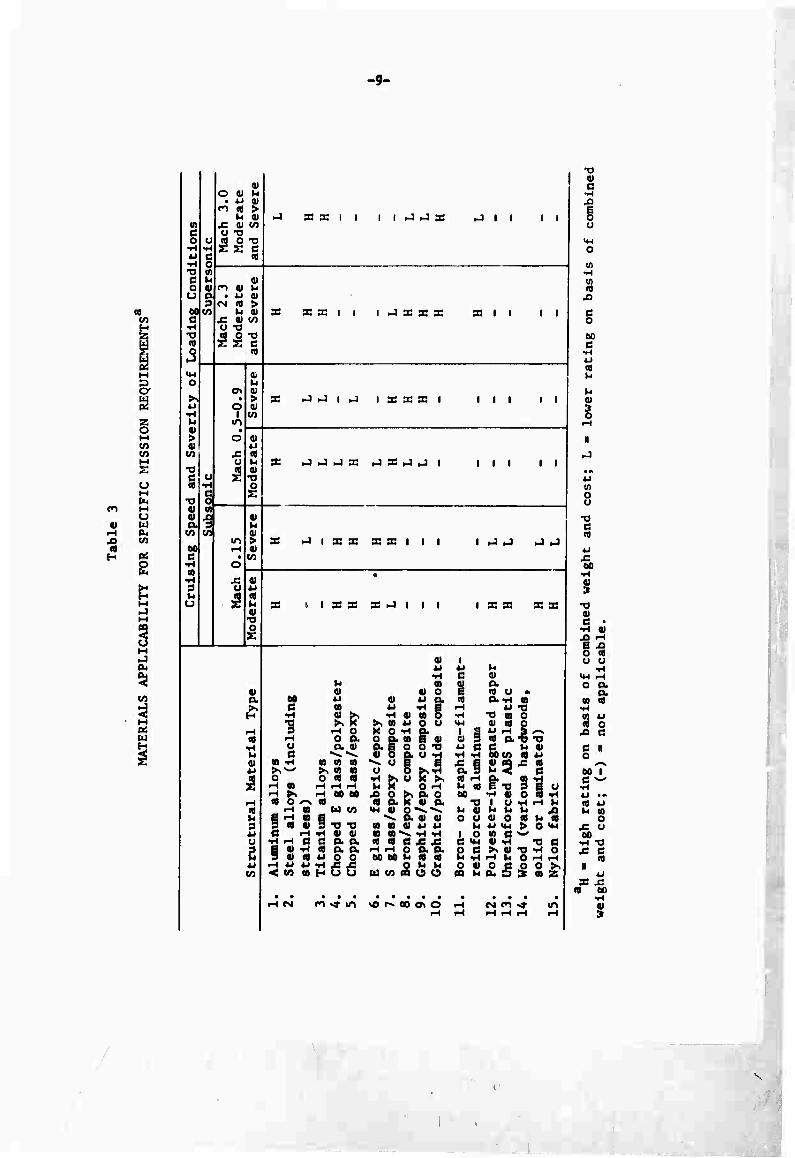
Table 3 has been constructed with these types of considerations
in mind. The primary emphasis of the present study is on air-launch
and recovery conditions, which are considered as moderate in this and
subsequent tables. However, more severe conditions such as would be
encountered during ground launch (e.g., by catapult) and particularly
during ground recovery (e.g., landing on wheels or skids) or ground
Impact via a parachute descent are also included for comparison.
Two supersonic cruise speeds are Included in Table 3; Mach 2.3
and Mach 3.0. The primary difference is the amount of aerodynamic
heating encountered. Temperatures at the vehicle surface of 29S0F to
SSS'F are typical for the Mach 2.3 cruise vehicle versus 550oF to öSO^F
for the Mach 3.0 cruise vehicle. As will be discussed in more detail
later, the higher temperatures associated with supersonic flight will
limit or eliminate many materials, including the aluminum alloys. In
Table 3 and subsequent tables, no distinction is made between moderate
and severe loading conditions for supersonic flight.
Whereas Table 3 summarizes the potential application of the various
materials to the complete airframe structure for various flight conditions.
-9-
PL, ri M
U (U W
rH Pu X> V) (0 H «
o
Pu s 3 M Pi W H
<u 1 O « l-i
• *J a» ri « >
M 0) HJ x ac I I i i fi »4 pa Uli * ' M Lc v en C O 73 0 u ^•g ■^ •H *J c «
o to
c u 01 o (U m 0> h o a
a • 4-1 0)
60 CO M 0) i X XXII 1 h-l X X X XII ' * c A v co •H U TS •o (D o i«
M-l
1
Of O
o\ u <u
>> I > X J J | J 1 X X X 1 III ' ' ^ o 0) ■H 1 to
0) • > o 0) 0) u
(A £ « T3
u u 01 XI
X _] _1 J X _l X J U 1 III II
u (0
c 1 •n 0)
o
0) xi 0) a M u
CA tn 01 m > X J 1 X X XXIII 1 U _! I-) tJ
00 iH 0* c • CO
« o 0)
• 3 u 4J
U S (0 I- 0) •a
X t 1 X X X -1 1 1 1 i x x xx
o J X
i 1 4J «J u •H a oi
u 10 0) o. i € tdu» i 01 01 01 o
i o- M *J 41 WO. (d (X-H a
1 ^ C to
■H OJ >, •a ►, ><
4i -rl g ■H oi n 5 •H -O «B O
>. n «J o u <*-< 0) « 0 1 1 •-• 3 ^ O
>-4 OP. X O -H g. o o. to e oi P. BO O T9 4) 0 P. U -H ^ o 1 e Ü 5 >s>H
•rt ►. O S >. MX O -H
1 S « rH S ^ i v 3 (d p.'o •o i
-H u a oi *J C C U V M e «s.««* i-t -H 60CO «d 4J
1 0) to -H a to ai ►.*-' ►» to to ilfl1!
5 o o <d <d td rH P. «0 M M cd e T) a e o fH to iH iH tH
^1 ►, rH 00 60 X) O >> P. O « P. K « a
00 -H « O <d -H t-t « O --s « •O \ U ^ r-t U \ «fl jH « W CO <« « o««^-^ U 9) U U U X> \
1 u
S « S 1 TS -a ^ P. 0) 0) o o o» o «d M id 0 m n v u u M M *M > O U-l \ u (3 iH ^1 0) Oi » n *^ -H -H i o to e ^ i o •H IH a e o. a «d «d c js J: c «4-t «) -H -a c 1 B 01 "H «o a P.
9 oi <a 4J o o rH H O P P o c >« « -a -H o oo ec M <d «d h ^1 rH U O rH rH
4-» ■< «O to H O Ö
o u u O 01 O p O O >% (/> U CO PQ U U> PQ M a. 5 se a 2
• • a • • • • • • ■ vo r^ oo a» o
• • • • • i iH CM CO St IT»
1 \ iH rH rH rH rH rH
-a ai c
•H XI
§ u
o
n) XI
C o oo c
u
u <u
o
II
CO o o
T5 c (0
•iH
I 01 c •
•H 01 •S ^ e x) o id u u
o P. a
to a iH (0 4-1 id o ^ c C II o 00 I c ^
>-i to o
J: u 00
•H "a x: c
id «
w X J=
id oo
0)
\
i \

-10-
Tables 4 through 7 indicate their applicability to specific components
of the structure. The same considerations apply, however, viz., cost,
excessive bulk, minimum-gauge limitations, operating temperatures, etc.

-11-
O
g i w
w I w Q
U
CO M
u o
o H in
I t M i-J
OK s I M
w H
1 .1 H J< 91 C 3 «
1«. (-•
»s V u u » 3
TJ U e u O 3 u u « u
(A tfl
• ■ 1 h
«4 It IB
4>1 « ■ ■ e 3 ■ •Ha« »x: b c x < M U
u ■ 0) u
■-I u C 3 M a
„ •i ti C rH
•H fH M « e o u a
z
a M ■ a w
c ■H *J
■H fc.
M • 3 3 S
b * h a M a a
»H e « •H
3 M u.
a & H
•-t a »4 1 a fi 2 ri a | 3 B I 2 w Ul
X J I ^1 X J J I I I IXI II
_! J I = I X I I I I I -J J J I
I X X X I I I I IHJX XI
i-l XIII I I I I I II
I IIXX>JIIII t J J J I
II^IXXIIII I J -J 11
X J I J X I I I I I I I ^1 II
i-l I I - X X _1 I I I ll>J XI
•-1 I I X X X >J I I I I X X -I
•o »> " 9 -HO -I o o. u a a c ^ ^
« -H a ■ ■ P &:: •HS -H r-l rH -H K -<«•«• a o -N a
Ma um
e -H -H a a ■ a 'H i o. o. 9 a a u o o
-H " « ■<H x x < in a H u o
■H a a o >> a u o o x o -H a o a a | a a 5 o. u -H
"o 0 8 >."
•J a o-^"^ ^ a a a
a a a w u Sa -^ »4 ^
a c £ J: tH IH o A a M w b a a
o i- w u) in a u u
■H -3
k> a o u
u i o C <M
«x-H a
T9 a o a a o a a* -a c ha UM a u
|« I |J a k« U IM > O <M a B «^ a *4 TI a
i >. a -a ^ o I »H h 0 H rH 1 o o o o ►>
a. D 3 a as
tHcs n^m so r^ CD c o »-* oim«» m
•Jlli-J IXIII I -1 i 11
-J >JIXXXIIII I J I >J I
I I I X X X I I I I I J J J I
-1 XIII I I I I I III II
I I I X X -I I I I I I J I ,JI
PS IIIS.-I.JIII III II
CB «llldlllll III I
I .J ,J X .J I I I III ^ I
I I ^ X X X I I i I J J IHI
a u • a o I a u - M u a u a a a -H a c ■ u M W r* w-S
•H a >. -H a a 5 .rt •o a o
1 ÄS &8^iü T iSil y
.5 o 9 8. a o <-.
-i •
18^
>. h J? • u »
II llHl M i-t H MM d iH
§^"5 a^a a u w •H a a a a>~ -n •n Sa & 9 a d x x
o. a. MM 8 o. a M o d «• « u a a
HUU UMMUO
a 9 a o.* -a wad urn
ti • (• h h X> o u a o a b a
M u <M > o *M i o a e ^ B v a «4 "O o o e >• a -o <ri o ta Vl rH b Q i-l f-l
•HM fn<»m <er>Mi
s ■a « e
: X
i
o o
9
s I 1
: X
5^ ti u a <•< b -<
a
■ ■ e
,

-12-
(U
■a H
t M ►J M
5 o M ►J
5 to I M 3 w H
1 J 11 II 3 " U. H
! ^ «I b b • 3
i ■0 "
° = <J h « u
j in <n
"J M C|
■H i k. •^ " j c
*-' v 9 ■ c 3 <d ■" x c (If b C X <
M U
1 " ■! « " rl O
31 • •'«
! C iH M rH
i « « Q U
U) ■ K
« • «1 g 31 w
1 1 3 b
h.
8 — a • M f.\ «I -^ ? s
v s H
•^ ■■ Vl
i H w
i u
1 *\ I *-*{
l\ \ H 3 u u
2 u Ul
J I Z I I
XX X J I
I I I X X X I I I I
XIII I I I I
1-1 I -11
l-l I J I
I X X J I I I I I J J J I
I I J X J X 1 I I III II
I I ■J I I I I I III I
X I I _! _1 -I .-1 I I I III i-4l
X I I -1 X J X J J I liJI 1-1
X K -I o o a a «
■H « ■ 5 -H o
u e
•H iH iH Ut
« 6 O, U -H -H <H
o 5 ^-n a 3
01 a (0 o • a-H a
4-1 T) •o « O 01 M O
n a* TJ c h «I DOM « 4J
-i >. <-i « « « O --v I«
•H « U U)
3 • 3 § -a T) e -i -H «) »
•H -i c c a o. B « -H ■ b O. 3 • • u o o fH W < m
H'lC Ä
_ >, a o a. K •) o.
■ ■ 01 w w
• <d c J= x IH FH o a. a oc M h a a
o b u u ui oa u o
u a M
ki «I 0 g i a c "M 25 S2
B -O 3 g <J ■-< 0) O • •rt I U -H f-4 ki b V> h A ai o • n i» U <M > O **-l 01 C ^ «I -H "O C >. «I "O -H O
•H b O iH r-4 O C O O >■. b 3 3 ■ K
^tirt ■& r*. ao as o •-*
X -1 I I I I X I I I
-I I X X X -1 I I I
I I I X X X I I I I
-I XIII I
I X X i-l I I I I
I 1-1-1 X X -1 -1 I
I I I I I
III 11
III 11
I I I I -1 X -1 -I I
1-1-1 X X -] -I I
CO e
1 o> ;>, -H
o o a. y (3
« -H « « n
o on« •H • iH <H iH I-I X IH eo M <o o — I»
iH « M tn
3 • S § T) -O 6 -I -H 0) «1
■H in c c a o. g o) -H « a. o. 9 « « u o o
•H U
01 o u a ■H e a o
« u o u O -H O.
o a « e o) o. B o o -o « 5 p. u TI
-^ o B B U O >.'H
•H >, U fc >, t< h O fH
JO O >s O. O « a fc o) a
•M o» o •^ ^ ^ a oi OP
«9 • • U U • • ^- ■H -H • «I B £ £ r-l rH O O. O. M M h <• (t
■ B ta u tn « u u
ill
o. _
no
125 •-< 01
I u >- h 01 o
o
§^ v. 01 I» u ■c ■ ■
i o c n o c M -H
(A C '
X 0)
O C 0. o
a > o >«
•a c T) -H O O r-l r-l O O >s
xi
01 c
n J3
tSC- ll iH
e xi •H Ifl U U n "* u —<
x: u o
» e
i<rir^ «or^ooavo —*

-13-
\o
J3 OS H
K M
M
3 u M
s i s u H
1 in ■-< -•<: a> ;: X _J _J I 1 1 x I 1 _l NJ 1 1 1 3 nj
1 u. H
1 >. aj :i u i- ' W 3 i -a u
c o \ X J -1 J J X X X X J .-111 1 ! O 3 ! u i- [ OJ u ! t« U1
1 o Of) c
•H U KJ 1 1 I J >J 1 1 1 33 III 1
j -H i "S
tfc
1 i-J « • i c 3 ra •H n) n •J 1=11 1 1 I 1 X J 1 1 1 oc x; v- c x <
UJ Ul
U Ul a; w
r-l u J 1 1 "1 »J rJ 1 1 1 X J 1 1 1 1 C 3
l-H 5
«) 01 u C "H
•H ^ <.n ai X ^1 .J I I 1 1 1 1 X XII 1 1 c u
UJ ID y.
<u 00 Ul cfl oo 1 a c 1 c •H 1 4J X XXII 1 ,J »I _) ,J •4 1 j i 1 a »J E •H
U3 U.
^^ 00 Ul c (U
<H e X »J J I I 1 X X X X XII 1 1 2i ni h
a u. UJ 00 ™ Ul
rH c M •H X »4 id 1 1 1 1 1 1 X XII 1 1 i ^ 3 to
U,
■ 4J M u l ■H C IV to 0) ai a i
w «i 01 0 6 cfl u • ! a 00 4.1 «i t-i a. m o. -H m { ^ C (0 U -Hg i-i u -a H •H « >, ft ti in o 14 X Bl 0 1
•o >, X >, <n u c u ■M Ql 18 0 i-H 3 ^10 x o -H a i e »j "-H 3 ^ 11 •H o a O D. Ul E 01 Ol 3 It CUT) 73
•H U O. 11) a E O O T3 w C C Wi 0) M C ««i."*. v o a u -H •H fl 01 1/J « iJ I 0) B) -H U) (A 01 ^- u E E ^: E o) « x: <fl w >.^-- X (B 9) o O >, -H o. 3 t. <: c
£ 0 O ns m ■H >, O X >, ra rt a «i -^ •H«) i-t i-l ^-1 Wi X Ort ^ ra E T: 3 e t- r-l >. rH 00 00 JO o >. tx. o 0C -H 0) O ID -H
rH (0 O -^ (TJ ig a x ti a •O | U -H rt ki (9 ^H 0) w to «-" «I o -«-^ 1- 01 t, t, »a ^) 1 U E >H in E »h. A.« « o u oi o a t, ig 1 3 3 (fl 01 3 "O -O ta at ci u u ^i U >M > O U-i 1 u C rt -H 4) 0) w m -«^ -H -H 1 O Ul c ^ u •H --; c c a a. <« eg c x f 1 <M fi <N "O C 1 3 e « -H (B a a rt —( o a a O C >. 01 T3 -rt O 1 u 3 «1 ifl *J o 0 oo oo w< i« eg t- -H — kl O --I —I 1 u H A M •■>) js ,2 0 J* G 0 11 o c o o >, m < 10 U) H o u uj in oa o O CC 1- ou a 3 Ml >» 1
»-4 csi o -^ in >0 r-. oo ON o rH <N rn -»^ ^ 1 t—■ $m ^-4 ^H ,-( rH 1
1 1
t
X c R
"3 11 C H
XI E 0
c
u;
in ID X
c o
oc c
flj >H
u 1)
II
Ul o u
■o c
X 0£
•H 01 3 -a 01 d
•H
f o o
Ul <1) X
c o ■
V 01, r-~
c X •r-t r3 *-> '^ ra —t >- rH
C x a. Of rj H
x *H
0 II i

-14-
H
C3Q
< U
a.
CO
< t-t Pi w
i
1 « III — Ji iij 41 C X _1 X 1 1 1 _1 1 IX XII ' ' 1 Ij 3 « ■ ^ ^
1 >, Hi t. k. U 'i CO 3 li TJ <J ii C U X -1=1-1 1 1 1 1 z XII ' ' 1 j 0 3 1 u t- 1, 01 u li w <*
! "i 1 t* ii c
■'"'
u 1 1 1 1 1 1 1 1 1 X III ' ' 1 •>-) fl) u
1 *"* Oi U) Ul c 3 m •" (n D 1 XXII 1 1 1 1 «J III ' * 1 M .r. t. C X < Ul u
u 10 i u
— u 1 XXII 1 1 1 1 X III ■ ' 1 C 3 - Q
<n i v ^ c -<
•H —I 00 4) 1 XXII 1 1 1 1 X III ' ' 1 C u
U4 1« !»,
1 ao Ul 1 n) 00 c c c •H
01 u J XXII 1 1 1 1 ~1 >J 1 1 ' ' 1 1 D- iJ
R ■»H u.
in 1 d u i -^ E -) XXII 1 1 1 1 X -J 1 1 ' ' 1 3
- u. 01 00
1 I« « ! r-4 c ! ^ •fH 1 XXII 1 1 1 1 X III ' '
<A ^ 3 Ul u.
V i *-J ^. u \ ■H g 0<
V. in V S- 1 • « a> o t. 10 O • |
1 0- Otl * > a^ 4-* a. IT a -^ m ►l C 1« W -HE w» W "3
'"' •p-* 4) >. •r-l OJ m o — ■3 m o -o >. X >. in ^ o u '*- O 10 o
[ f—* 3 —i 0 x o -^ a I E w ^ 3 ~ n -i 0 o. o c- in e OJ 3 X O. T3 T3 1
■^ o a. ») a E O O T3 *^ C C U v \ \ u c --- ~- 0) o a u -^ —1 •«-i oo i/i nj *-* j ! 11 tn ■- in 'o in ~- u E E X E i 33 i 10 1 \ *-* >.^- ^ Ml «1 u O >.•* r 3 >- < C
(0 O O «J <T1 •H >. O X >. r —•a. in -^ 1 I '' V. X o — v. m r -a 3 E - 1
-i > —. 00 ^ ja e >. & c 91 — U O 10 -< 1 \ ,—1 « o <^ n to o. x oi a 73 1 u •-< —1 »1 1 ! ^ ~ tr ^- tr. <•.. a» o — -~. V- 1/ i- U k, J3 1
u Ü — Vl E »* Bt tt V \ U V O « h «I 1 1 3 3 tfl 0) 3 73 -G in m o> «-• u k. 4-1 14-1 > Q •- 1
1 * ' C —. -H 0) OJ en in "^ -^ -H I O if. C -' • u -< —• c c o. o. « io C ^: ^ g •4-4 i -H "3 C 1
1 3 E 1) -H W D. CL r-< r-4 O O. Ct ' C >. 0» 73 -H Ol
J ^ 3 0) (0 4J O 0 oo oo i- M n C •H —4 kt O ^H —1 1
'' ^^ 4-i »J -^ j^ x: Q U U ^ • c a o o >.l U-. -: v) td — u U - 'X. x o u Vi t, LJ D: ui :'. 1
_ ri -« -t i" x t ■- r c^ o M rl -> -l i^ 1
1
c
73 C It
0/
li 3
"0 a r -c E C
73 C .7!
-J
73
-C E c
w- —i
a.
II c
X II

-15-
IV. TYPICAL AIRFRAME-MATERIAL COMBINATIONS
The material combinations considered here are representative of
those currently available for subsonic- and low-supersonlc-crulse
vehicle applications and were selected to emphasize the performance
of a particular material, or to attain a particular objective, e.g.,
low cost or low weight. Effects of elevated-temperature environments
(typical of hlgh-supersonic-cruise vehicles) will be considered later.
Obviously, other combinations of the same materials, or additional
materials, could also be considered. However, those presented hexe
are believed to cover the range of possibilities reasonably well.
All rankings are In relation to all-aluminum structures, and
broad comparatives have been used, e.g., moderately Increased, greatly
Increased, moderately decreased, and greatly decreased. The extreme
cases for a particular characteristic are also Indicated, e.g., high-
est and lowest.
While the primary emphasis here Is on weight comparisons, alrframe
cost and durability are also compared In the following brief discus-
sions of nine potentially applicable material combinations. Durability
Is loosely defined to Include such factors as resistance to damage due
to ground handling, adverse flight and storage environments, and struc-
tural fatigue. Also Included are relative ease of maintenance. Inspec-
tion, and repair, all of which are Important factors in multiple-flight
drone applications.
ALUMINUM
The weights of the individual structural components for the all-
aluminum configurations, which will be used as the bases of comparisons
for all the suosonic-cruise vehicles, have been estimated by the design
method previously described. Since few actual design data points are
currently available for the relatively small vehicles being analyzed
here, the?e weights were obtained using appropriate performance scaling
factors. These typically require extrapolations rather than interpola-
tions. Thus, the construction methods for these small alrframes may be
different from those used in larger vehicles. For example, greater use
~T~

-16-
of ring-stiffened monocoque fuselages and full-depth honeycomb-core wing
and tall structures can be anticipated; the component weights of the
aluminum structures Indicated here assume the most efficient construc-
tion method Is used for the particular application. Another problem,
that of encountering minimum-gauge limitations, has not been explicitly
considered. Some weight estimates would have to be Increased If such
limitations were encountered In an actual detailed design. The same
consideration will also apply to the other material combinations being
considered, however.
FIBERGLASS
Fiberglass construction, like all-aluminum construction, repre-
sents an adequately proven state of the art. The Increased durability
of fiberglass Is due In part to the absence of corrosion problems and
the ease of repair of minor damage. Fiberglass has an outstanding
strength-to-weight ratio, but only an average stiffness-to-welght ratio.
Hence, It Is most advantageously utilized In strength-critical struc-
tures. A moderate overall weight reduction can be expected. Although
Its basic material cost Is higher than that of aluminum, fabrication
costs are at least comparable. Hence, the cost of a finished part Is,
at most, only moderately higher. Flberglass/epoxy Is a radar-transparent
material, while aluminum Is not.
FIBERGLASS WITH PAPER HONEYCOMB CORE
Replacing the S glass/epoxy wing of an all-fiberglass design with
a paper phenolic honeycomb-core/aluralnum-skln wing offers an additional
weight reduction and a lower cost. The paper phenolic honeycomb core
precludes the possibility of a wet wing, however. It Is also a less
rugged construction than the S glass/epoxy sheet and spar construction,
and thus provides lower system reliability. Another alternative would
be the use of unidirectional S glass wing skins In place of the alumi-
num, particularly for radar-cross-section reduction. This combination
Is comparable to aluminum In cost and durability.

-17-
CAST AND MOLDED PLASTICS
Chopped E glass/polyester centrifugally cast tubing of the re-
quired size Is commercially available. Its use will require a constant
fuselage diameter and specially cast nose and tall closures. However,
a specially cast entire fuselage (In two or three sections) Is a pos-
sible alternative. The actual cost of the ABS molded plastic wing will
depend somewhat upon the quantities produced because of the high non-
recurring costs of the required molding equipment. Because of the poor
elevated-temperature properties of polyester, the engine nacelle would
be of standard aluminum construction. The total alrframe weight would
be high because of the relatively low strength and stiffness character-
istics of these plastic materials. The resulting alrframe, except the
aluminum nacelle, would be radar-transparent, however. Cost would be
greatly reduced and durability moderately Increased.
PAPER AND FOAM
The combination of paper and foam can be expected to lead to
greatly reduced cost and moderately reduced weight, but low durability.
Polyester-Impregnated, spiral-wound paper tubing In the required size
Is commercially available. Nose and tall cones to close out the
constant-diameter mldsectlon must be specially molded, using chopped-
E-glass-relnforced or unrelnforced polyester moldings. The polyurethane-
foamed wing has natural skins and hence limited durability. As In the
cast and molded plastic combination, standard aluminum nacelle con-
struction would be used.
HOOD
Wood construction can be expected to lead to moderately reduced
weight, moderately Increased cost, and moderately reduced durability.
Sltka spruce has good stlffness-to-welght properties and Is an excel-
lent framing material. Mahogany plywood has good shear properties and
Is an efficient skln-coverlng material. The combination results In a
lighter structure than aluminum. Fabrication costs would be higher
though, and wood requires frequent maintenance, e.g., reflnlshlng.
Like the plastics. It Is radar-transparent.
■

-18-
SAIL-WING DESIGN
For those limited missions where it is applicable, e.g., high-
altitude, low-speed missions, the sail-win^ offers a significant weight
savings, as well as lower cost. Nylon cloth has been assumed here but
other fabrics can also be utilized. The stowability of a flexible wing
can be an advantage in certain launch and recovery systems. Obviously,
the sail-wing could be combined with fiberglass/epoxy fuselage and tall
structures to reduce the total alrframe weight even more. This would
also increase the radar transparency but would Increase the cost. Dura-
bility of sail-wings may be low.
GRAPHITE-FILAMENT/EPOXY COMPOSITES
Graphite-fllament/epoxy composites are expected to have the lowest
weight, greatly increased durability, and the highest cost. Graphite/
epoxy has a very low density and high strength and stiffness properties.
Graphite filament presently costs about $240/lb. However, fabrication
costs are comparable to those of aluminum. This material is Included
to indicate the present potential of filament-reinforced composites.
The near-term (2- to 5-year) cost-reduction potential of this material
is very high; and eventual costs as low as $1.00 to $2.00/lb are being
projected, which are near the current $0.50 to $1.50/lb cost of alumi-
num alloys. Boron filament offers similar high performance, at a com-
parable high cost. However, the near-term cost-reduction potential is
much less.
TITANIUM ALLOYS
Use of titanium alloys would lead to moderately reduced weight and
moderately increased durability, but greatly increased costs. Titanium,
like graphite/epoxy, is not a cost-effective material for low-performance
drone applications. Only when weight savings become extremely important,
as for very high-altitude operation, or when thermal environments become
severe, as beyond about Mach 2.5, can titanium compete with or replace
aluminum. Both material cost and fabrication costs are high relative
to those of aluminum. Unlike graphite/epoxy, titanium does not appear
to have a large cost-reduction potential in the near future.

-19-
OTHER POSSIBILITIES
Steel alloys were Included In Tables 1 through 7 for comparison
purposes but have not been specifically discussed. Having specific
strengths and stiffnesses comparable to those of aluminum but being
almost three times as dense, steel alloys are subject to minimum-
gauge limitations in the low-performance applications being considered
here.
Graphite/polylmide composites have room-temperature mechanical
properties comparable to those of the graphite/epoxy composites (as do
the various other polylmlde matrix composites when compared to their
epoxy matrix counterparts). Since, as Table 1 Indicates, they are
both slightly more expensive end more difficult to fabricate, they
would not normally be used in place of the epoxy-matrix composites when
temperature is not a consideration. Thus, they have not been discussed
here.
The high cost and lack of well-developed fabrication processes
for filaments tend to eliminate the boron- or graphite-filament-
reinforced aluminum composites from current applications to subsonic
vehicles. However, even as the cost of the filaments is reduced and
better fabrication methods are established, the metal matrix composites
will probably not be competitive with the plastic matrix composites for
subsonic vehicles. Because of their higher density (aluminum is about
twice as dense as epoxy), smaller weight savings are probable, as indi-
cated in Table 1.
Beryllium offers weight advantages In the subsonic and low super-
sonic range. It is costly, has low ductility, and poses fabrication
problems. Although it was not included in this study, there may be
applications for this material.
■
•
-20-
V. AIRFRAME STRUCTURAL WEIGHT COMPARISONS FOR VARIOUS MATERIAL COMBINATIONS
The nine combinations described above will now be considered for
specific drone applications and compared on a detailed structural-weight
basis. Subsonic cruise vehicles will be compared separately from super-
sonic vehicles, since aerodynamic heating effects are negligible for
subsonic flight. Many of the material combinations considered have a
very limited elevated-temperature resistance and must be eliminated from
consideration for supersonic cruise vehicles on this basis alone. Other,
more suitable materials will be Introduced as required.
The weights of the Individual structural components for an assumed
basic vehicle configuration were obtained using a design analysis de-
veloped at Rand. ' The total weight of the tall assembly Is assumed
to be 25 percent that of the wing. The weight of the nacelle lu
assumed to be 7-1/2 percent that of the engine for the subsonic drones,
and 10 percent for the supersonic drones.
SUBSONIC CRUISE VEHICLES
Five specific subsonic drone configurations will be analyzed in
detail here. These configurations, generated using a design method
developed at Rand, ' have been chosen to be representative of vehicles
designed for a number of types of drone missions. Their character-
istics and performance are given In Table 8.
The first two configurations are designed for low-speed, moder-
ately hlgh-altltude (55,000 ft), long-endurance missions; the principal
difference between them Is the type of propulsion system used. Con-
figurations 3, 4, and 5 are designed for hlgh-subsonlc-speed cruise
missions—Configuration 3 for low-altitude, 1000-n ml range, and 4 and
5 for hlgh-altltude (75,000 ft), long range (2500 and 5500 n ml, re-
spectively) .
The Influences of both cruise speed and launch and recovery loads
on materials selection were Indicated qualitatively In Tables 3 through
7. It was shown that the low-performance (and typically low-cost)
materials are most likely to be considered for subsonlc-crulse-speed

-21-
O w H u w I to w
u V)
I u
oo u
ua o id w H g
en
i c
■H 00
Reciprocating proo
Turboprop
Turb
ofan
Turbofan
Turbofan
Structural
Weighta
(lb) C fi oc ro m vc cs oc m oc
r- vc P-J vc a • *
tH H
Payload
Weightb
(lb) c c c c c
c c m c c r- r^ ro p~ r-»
Gros
s Weight3
(lb) c c c c c
c c c c o o m c c c
M * M » A \o m esj ro oc
Crui
se
Range
(n mi)
• •
• •
1000
2500
5500
Cruise
Endurance
(hr)
H m • • • CM CNJ
Crui
se
Altitude
(ft)
55,000
55,0
00
Sea
leve
l 75
,000
75,0
00
Crui
se
Speed
(kn)
INJ m o io m r>- r^ o >-t «-I tH CM m in u-i
§ ■H
00
i i-t CM co sr m
0) B id 0) u 4J
w 01 >s in tn n)
x> c o •> •H
c 4J o CO
•H 00 u •H O > 3 CO u c u 05 •a C a o CO u
0) H o 3 c C id
•H •n K •H 3 3
rH 00 10 1 to
rH 0) rH Tl 10 3
rH u o o c
-22-
drones and moderate design load factors. Configurations 1 through 5
all assume moderate design loads. The most significant effect of
changing this to a more severe loading would be an Increase in the
structural weight fraction as the airframe is strengthened to carry
the additional loads. This Increase in structural weight would corre-
spondingly Increase the potential for total weight savings obtainable
by materials substitution.
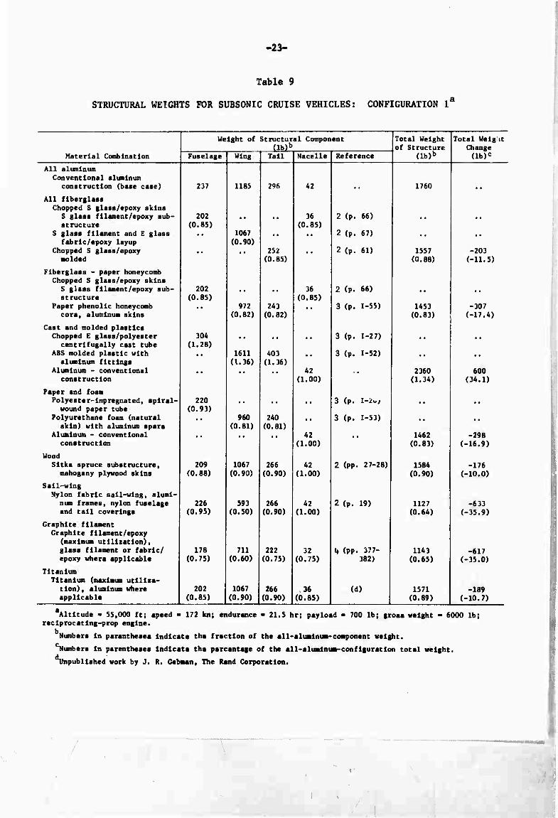
Detailed structural-weight breakdowns for the five subsonic
cruise vehicles are presented in Tables 9 through 13. The numbers in
parentheses under the heading "Weight of Structural Component" Indicate
the fractions of the weight of the all-aluminum component which have
been assumed to be attainable by the indicated materials substitution.
These fractions are based in part upon the weight-savings estimates
presented in Table 1 for individual materials. They are also in-
fluenced by actual detail design studies, as referenced. Obviously
the values tabulated here, as well as those given in Table 1, must
be considered only as typical values. A detailed design study of
each component of a specific configuration is necessary to obtain
specific weight estimates.
These weight fractions are then used to compute the component
weights indicated. The last two columns indicate, respectively, the
total weight of the airframe structure for each material combination
(and, in parentheses, this weight as a fraction of the weight of the
all-aluminum configuration) and the total weight change,from the all-
aluminum configuration (and, in parentheses, this change as a percent-
age of the all-aluminum-configuratlon total weight). Only the cast
and molded plastic material combination results in a net weight increase.
As suggested earlier, this combination is included because of Its
potential for low cost.
Although the airframe loadings for the drone missions being
considered here are not severe, the importance of reducing structural
weight as the mission becomes more taxing can be appreciated by
comparing Configurations 1 and 2. As previously stated, the mission
for these two designs is the same, viz., long-endurance flight at
55,000 ft altitude. However, a reciprocating engine is assumed in
-23-
Table 9
STRUCTURAL WEIGHTS FOR SUBSONIC CRUISE VEHICLES: CONFIGURATION le
Weight of Structural Component 1 Total Weight Total Weig it (lb)" lof Structure
j (lb)b Change
Material Combination Fuselage [ Wing Tail Nacelle Reference (lb)c
All aluminum Conventional aluminum
construction (base case) 237 1185 296 42 • ■ 1760 • •
All fiberglass Chopped S glass/epoxy skins
S glass fllament/epoxy sub- 202 . , ,. 36 2 (p. 66) . , .. structure (0.85) (0.85)
S glass filament and E glass . . 1067 ,. , . 2 (p. 67) a . ,. fabrlc/epoxy layup (0.90)
Chopped S glass/epoxy • • 252 . . 2 (p. 61) 1557 -203 molded (0.85) (0.88) (-11.5)
Fiberglass - paper honeycomb Chopped S glass/epoxy skins
S glass filament/epoxy sub- 202 . , 36 2 (p. 66) ,, a ,
structure (0.85) (0.85) Paper phenolic honeycomb , • 972 243 . , 3 (p. 1-55) 1453 -307
core, aluminum skins (0.82) (0.82) (0.83) (-17.4)
Cast and molded plastics Chopped E glass/polyester 304 .. ,, 3 (p. 1-27) a . a .
centrlfugally cast tube (1.28) ABS molded plastic with . . 1611 403 , a 3 (p. 1-52) a a a ,
aluminum fittings (1.36) (1.36) Aluminum - conventional , a , . , , 42 •. 2360 600
construction (1.00) (1.34) (3A.1)
Paper and foam Polyester-impregnated, spiral- 220 . , ., 3 (p. I-2o/ a , . • wound paper tube (0.93)
Polyurethane foam (natural .. 960 240 ,. 3 (p. 1-53) a ,
skin) with aluminum spars (0.81) (0.81) Aluminum - conventional ,, ,, 42 , , 1462 -298
construction (1.00) (0.83) (-16.9)
Wood Sitka spruce substructure. 209 1067 266 42 2 (pp. 27-28) 1584 -176 mahogany plywood skins (0.88) (0.90) (0.90) (1.00) (0.90) (-10.0)
Sail-wing Nylon fabric sail-wing, alumi- num frames, nylon fuselage 226 593 266 42 2 (p. 19) 1127 -633 and tail coverings (0.95) (0.50) (0.90) (1.00) (0.64) (-35.9)
Graphite filament Graphite filament/epoxy
(maximum utilization). ■
glass filament or fabric/ 178 711 222 32 it (pp. 377- 1143 -617 epoxy where applicable (0.75) (0.60) (0.75) (0.75) 382) i (0.65) (-35.0)
Titanium Titanium (maximum utiliza-
tion) , aluminum where 202 1067 266 36 (d) 1571 -189 applicable (0.85) (0.90) (0.90) (0.85) (0.89) (-10.7)
Altitude - 55,000 ft; speed - 172 kn; endurance - 21.S hr; payload - 700 lb; gross weight - 6000 lb; reclprocatlng-prop engine.
Numbers in parentheses indicate the fraction of the all-aluaintmi-component weight.
Numbers in parentheses Indicate the percentage of the all-alumima-conflguratlon total weight.
Unpublished work by J. R. Gebaan, The Rand Corporation.
•-■■■■■■■■■»■

-24-
Table 10
STRUCTURAL WEIGHTS FOR SUBSONIC CRUISE VEHICLES: CONFIGURATION 2
\«
Material Combination
All aluminum Conventional aluminum
construction (base case)
Fiisrlag»
IHK
All fiberglass Chopped S glass/epoxy skins
S glass fllament/epoxy sub- structure
S glass filament and E glass fabric/epoxy layup
Chopped S glass/epoxy nolded
160 (0.85)
Fiberglass - paper honeycomb Chopped S glass/epoxy skins
8 glass fllament/epoxy sub- structure
Paper phenolic honeycomb core, aluminum skins
160 (0.85)
Cast and molded plastics Chopped K glass/polyester
centrlfugally cast tube ABS molded plastic with
aluminum fittings Aluminum - conventional
construction
241 (1.28)
Paper and foam Polyester-impregnated, spiral- wound paper tube
Polyurethane foam (natural - skin) with aluminum spars Aluminum - conventional construction
175 (0.93)
Wood Sitka spruce substructure, mahogany plywood skins
165 (0.88)
Sail-wing Nylon fabric sail-wing, alumi- num frames, nylon fuselage and tail coverings
179 (0.95)
Graphite filament Graphite fllament/epoxy
(maximum utilization), glass filament or fabric/ epoxy where applicable
141 (0.75)
Titanium Titanium (maximum utiliza-
tion), aluminum where applicable
160 (0.85)
Wpight of Structural Componpnt
ühlV- [ Wing Tail Nacelle
333 83 19
j 300 (0.90)
71 (0.85)
16 (0.85)
j
274 (0.82)
68 (0.82)
16 (0.85)
453 (1.36)
113 (1.36)
19 (1.00)
271 (0.81)
68 (0.81)
19 (1.00)
{ 300 (0.90)
75 (0.90)
19 (1.00)
167 (0.50)
75 (0.90)
19 (1.00)
1 200 (0.60)
62 (0.75)
14 (0.75)
300 1(0.90)
75 (0,90)
16 (0.85)
Kcforrnce
Total Weiglit Total Weight r>f Strnrtiirt' Change
b
2 (p. 66)
2 (p. 67)
2 (p. 61)
2 (P
3 (p
3 (P
3 (P
3 (P
3 (P
2 (pp
66)
I-V.)
1-17)
1-5.0
[-.!(>)
!->))
27-JH)
2 (p. 19)
It (pp. 377- 1K2)
(.1)
(lb)f
623
547 (0,88)
V1X (0.81)
826 (1.33)
(lb)'
-76 (-12.2)
-105 (-16.8)
20 J (32.6)
5 31 -90 (0.R6) (-14.5)
559 -64 (0.90) (-10.3)
440 -183 (0.71) (-29.4)
417 -206 (0.67) (-33.1)
551 -72 (0.88) (-11.6)
"Altitude - 55,000 ft; speed - 273 kn;. endurance - 23.7 hr; payload = 700 lb; gross weight ■> 3500 lb; turboprop engine.
Numbers in parentheses indicate the fraction of the all-alumlnum-component weight.
Numbers in parentheses Indicate the percentage of the all-alumlnum-conflguration total weight.
Unpublished work by J. R. Gebman, The Rand Corporation.

-25-
Table 11
STRUCTURAL WEIGHTS FOR SUBSONIC CRUISE VEHICLES: CONFIGURATION 3£
Weicht of Structural Compor (lb)!5
ent Total Weight of Structure
(lb)b
Total Weight Change
Material Combination Fuselage Wing Tail Nacelle [ Reference (lb)c
All aluminum Conventional aluminum
construction (base case) 250 26 6 6 288 a •
All fluerglass Chopped S glass/epoxy skins
S glass fllament/epoxy sub- structure
S glass filament and E glass fabric/epoxy layup
Chopped S glass/epoxy molded
212 (0.85)
• •
23 (0.90)
5 (0.85)
5 (0.85)
2 (p. 66)
2 (p. 67)
2 (p. 61) 24S (0.85)
..
..
-43 (-14.9)
Fiberglass - paper honeycomb Chopped S glass/epoxy skins
S glass fllament/epoxy sub- structure
Paper phenolic honeycomb core, aluminum skins
212 (0.85)
21 (0.82)
5 (0.82)
5 (0.85)
2 (p. 66)
3 (p. I-5r,) 243 (0.84)
-45 (-15.6)
Cast and molded plastics Chopped E glass/polyester
centrlfugally cast tube ABS molded plastic with
aluminum fittings Aluminum - conventional
construction
320 (1.28)
35 (1.36)
8 (1.36)
6 (1.00)
3 (p- 1-27)
3 (p. 1-52) ■ •
369 (1.28)
81 (28.1)
Paper and foam Polyester-Impregnated, spiral- wound paper tube
Polyurethane foam (natural skin) with aluminum spars
Aluminum - conventional construction
232 (0.93)
21 (0.81)
5 (0.81)
6 (1.00)
3 (p. 1-26)
3 (p. 1-53) • ■
264 (0.92)
• •
-24 (-8.3)
Wood Sltka spruce substructure, mahogany plywood skins
220 (0.88)
23 (0.90)
5 (0.90)
6 (1.00)
2 (pp. 27-28) 254 (0.88)
-34 (-11.8)
Sail-wing Nylon fabric sail-wing, alumi-
num frames, nylon fuselage and tail coverings
•• •• • • •• • • • •
Graphite filament Graphite filament/epoxy
(maximum utilization), glass filamciit or fabric/ epoxy whern .pplicable
188 (0.75) |
16 (0.60) (0.75)
5 (0.75)
h (pp. 377- 382)
213 (0.74)
-75 (-26.0)
Titanium Titanium (maxlmuii utiliza-
tion), aluminum where i applicable
212 (0.85) |
23 (0,90)
5 (0.90)
6 (0.85 |
(d) 1 246 (0.85)
-42 (-14.6)
Sea level; speed - 500 kn; range " 1000 n at; payload « 350 lb; gross weight ■ 2000 lb; turbofan engine.
Numbers in parentheses Indicate the fraction of the all-aluminun-component weight.
"Numbers in parentheses Indicate the percentage of the all-aluminum-configuration total weight.
Unpublished work by J. R. Gebman, The Rand Corporation.

-26-
Table 12
STRUCTURAL WEIGHTS FOR SUBSONIC CRUISE VEHICLES: CONFIGURATION 4
Weight of Structural Component Total Weight Total Weight (lb)" ot Structure
(ll.)b Change
Material Combination Fuselage Wing Tall Nacelle Reference (lb)c
Ail aluminum Conventional aluminum construction (base case) 189 345 86 33 653
All fiberglass Chopped S glass/epoxy skins
S glass fllament/epoxy sub- 161 . , 28 2 (p. 66) , , .. structure (0,8S) (0.85)
S glass filament and E glass , , 310 , 1 2 (p. 67) , , .. fabrlc/epoxy layup (0.90)
Chopped S glass/epoxy . . 73 2 (p. 61) 572 -81 molded (0.85) (0.88) (-12.4)
Fiberglass - paper honeycomb Chopped S glass/epoxy skins
S glass filament/epoxy sub- 161 . • 28 2 (p. 66) . . . , structure (0.85) (0.85)
Paper phenolic honeycomb a . 283 70 , , 3 (p. 1-55) 542 -111 core, aluminum skins (0.82) (0.82) (0.83) (-17.0)
Cast and noHed plastics Chopped K glass/polyester 242 , , • * , , 3 (p. 1-27) , , ,.
centrlfug.il ly cast tube (1.28) ABS molded plastic with . , 469 117 , , 3 (p. 1-52) , , ,.
aluminum fittings (1.36) (1.36) Aluminum - conventional , # i ■ • • 33 . . 861 208
construction (1.00) (1.32) (31.9)
Paper and foam Polyester-Impregnated, spiral- 176 t a . . • • 3 (p. 1-26) • • ,, wound paper tube (0.93)
Polyurethare foam (natural • . 279 70 • • 3 (p. 1-53) • • .. skin) with aluminum spars (0.81) (0.81)
Aluminum - conventional , , • • • * 33 , , 558 -95 construction (1.00) (0.85) (-14.6)
Wood Sitka spruce substructure. 166 310 77 33 2 (pp. 27-28) 586 -67 mahogany plywood skins (0.88) (0.90) (0.90) (1.00) (0.90) (-10.3)
Sail-wing Nylon fabric sail-wlnjt, alumi-
num frame*, nylon fuselage 180 173 77 33 2 (p. 19) 463 -190 and tail coverings (0.95) (0.50) (0.90) (1.00) (0.71) (-29.1)
Graphite filament Graphite filament/epoxy
(maximum utilization). glass filament or fabric/ 142 207 64 25 4 (pp. 377- 438 -215 epoxy where applicable (0.75) (0.60) (0.75) (0.75) 382) (0.67) (-33.0)
• Itanium Titanium (maximum utiliza-
tion), aluminum where 161 310 77 28 (d) 576 -77 applicable (0.85) (0.90) (0.90) (0.85) (0.88) (-11.8)
Altitude • 75,000 ft; speed - 515 kn; rani« - 2500 n mi; payload • 700 lb; gross weight - 3000 lb; turbo- fan engine.
Numbers in parentheses indicate the fraction of the all-alunlnum-component weight.
Numbers in parentheses indicate the percentage of the «ll-alumlma-conflguratlon total weight.
Unpublished work by J. R. Gebman, The Rand Corporation.

^27-
Table 13
STRUCTURAL WEIGHTS FOR SUBSONIC CRUISE VEHICLES: CONFIGURATION 5C
Weight of Structural Component 1 Total Weight Total kVight (lb)b of St ructure
(ll>)b Cliangt*
Material Combination Fuselage Wing Tall Narelle Reference (11.)'
All aluminum Conventional aluminum
construction (base case) 344 1248 312 81 1985 .. All fiberglass
Chopped S glass/epoxy skins S glass filament/epoxy sub- 292 . . 69 2 (p. 66) .. structure (0.85) (0.85)
S glass filament atJi 3 glass , , 1123 , 2 (p. 67) . . * fabrlc/epoxy layup (0.90)
Chopped S glass/epoxy , . . . 265 . . 2 (p. 61) 1749 -236 molded (0.85) (0.88) (-11.9)
Fiberglass - paper honeycomb Chopped S giass/epoxy skins
S glass filament/epoxy sub- 292 , . . . 69 2 (p. 66) • • , , structure (0.85} (0.85)
Paper phenolic honeycomb , , 1023 256 ,, 3 (p. 1-55) 1640 -345 core, aluminum skins (0.82) (0.82) (0.83) (-17.4)
Cast and molded plastics Chopped £ glass/polyester 440 , , , _ ,, 3 (p. X-27)
centrlfugally cast tube (1.28) ABS molded plastic with , , 1697 424 3 (p. 1-52)
aluminum fittings (1.36) (1.36) Aluminum - conventional , , ., , , 81 , , 2642 657
construction (1.00) (1.33) (33.1)
Paper and foam Polyester-impregnated, spiral- 320 , , , . 3 (p. i-:6) ,, wound paper tube (0.93)
Polyurethane foam (natural , , 1010 253 i , 3 (p. 1-53) skin) with alunlnum spars (0.81) (0.81)
Aluminum - conventional , , m , 81 1664 -321 construction (1.00) (0.84) (-16.2)
Wood Sitka spruce substructure. 302 1123 281 81 2 (Pp. 27-28) 1787 -198 mahogany plywood skins (0.88) (0.90) (0,90) (1.00) (0.90) (-10.0)
Sail-wing Nylon fabric sail-wing, alumi-
num frames, nylon fuselage 326 624 281 81 2 (p. 19) 1312 -673 and tail coverings (0.95) (0.50) (0.90) (1.00) (0.66) (-33.9)
Graphite filament Graphite filament/epoxy
(maximum utilization). glass filament or fabric/ 258 749 234 61 It (pp. 377- 1302 -683 epoxy where applicable (0.75) (0.60) (0.75) (0.75) 382) (0.66) (-34.4)
Titanium Titanium (maximum utiliza-
tion), aluminum where 292 1123 281 69 (d) 1765 -220 applicable (0.85) (0.90) (0.90) (0.85) (0.89) (-11.1)
Altitude - 75,000 ft; speed - 515 kn; range ■ 5500 n ml; payload - 700 lb; gross weight - 8000 lb; turbo- fan engine.
Numbers In parentheses Indicate the fraction of the all-alumlnum-component weight.
Numbers in parentheses Indicate the percentage of the all-aluolnum-conflguratlon total weight.
Unpublished work by J. R. Cabman, The Rand Corporation.
I

re-
configuration 1, and a turboprop engine In Configuration 2. For max-
imum endurance, the cruise speed for the reciprocating engine Is only
172 kn, compared to 273 kn for the turboprop. The lower speed requires
a wing area much greater than that for the turboprop vehicle, resulting
In a significantly greater alrframe weight. The weight of the fuel
required Is correspondingly Increased—by about 59 percent. Also, the
reciprocating engine Is more than twice as heavy as the turboprop.
The net effect. Is a 72 percent Increase In gross vehicle weight—and
a 182 percent Increase In alrframe structural weight. That is, the
structural weight fraction jumps from less than 0.18 for the turboprop
vehicle to more than 0.29 for the reciprocating-engine vehicle.
Thus, Configuration 1 is an example of the detrimental effect of
taxing the operating capability of a particular vehicle (in this case,
by requiring a reciprocating engine to operate at a high cruise alti-
tude) Obviously, the reductions in structural weight obtained by the
materials substitutions indicated in Table 3 are much more significant
in this case, where the structural weight fraction is large, than in
Configuration 2, where it is relatively small.
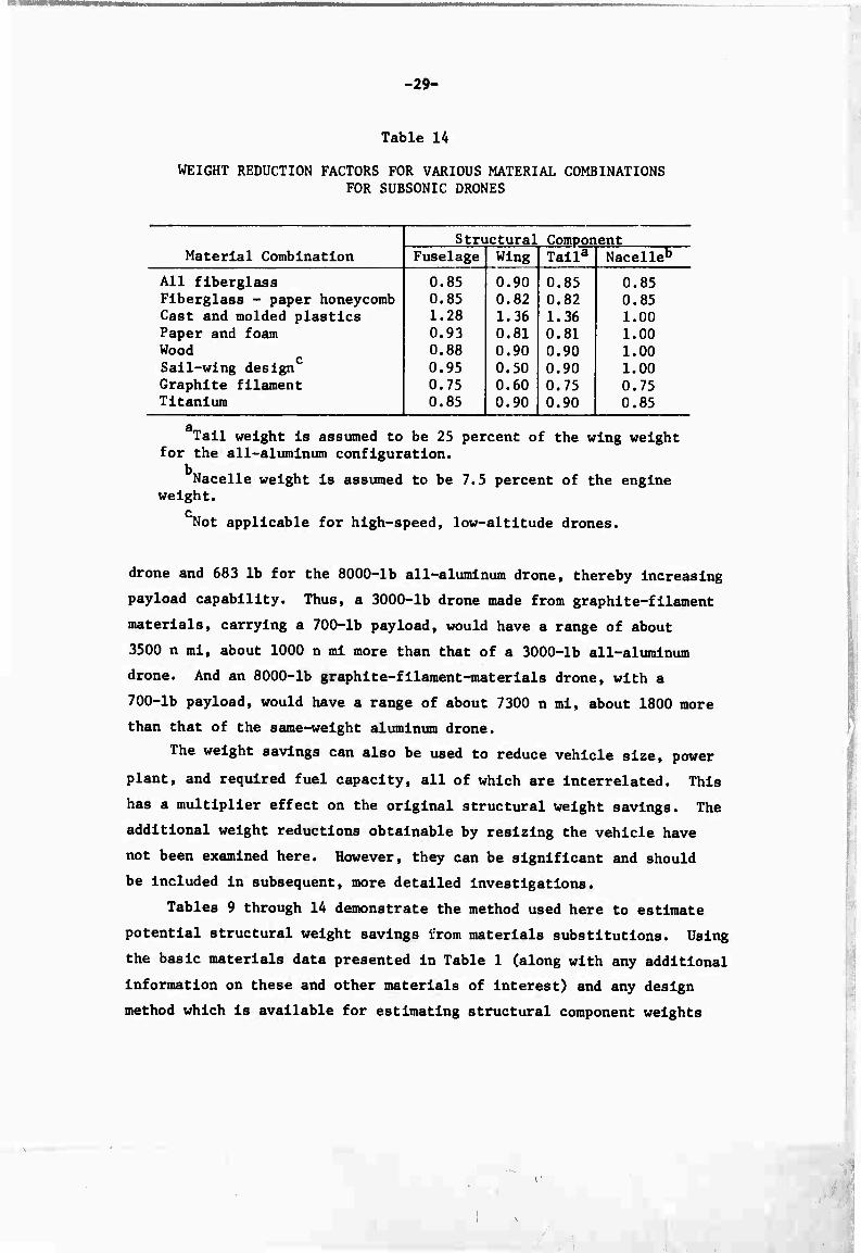
The results presented in Tables 9 through 13 can be summarized in
terms of a set of weight reduction factors that operate on the fuse-
lage, wing, tail, and nacelle weights obtained for all-aluminum con-
struction. These factors are given in Table 14 for each material
combination. One can design a vehicle and determine the weights of
the various structural components when made from aluminum, and then
estimate the weight savings with different materials by applying
these factors.
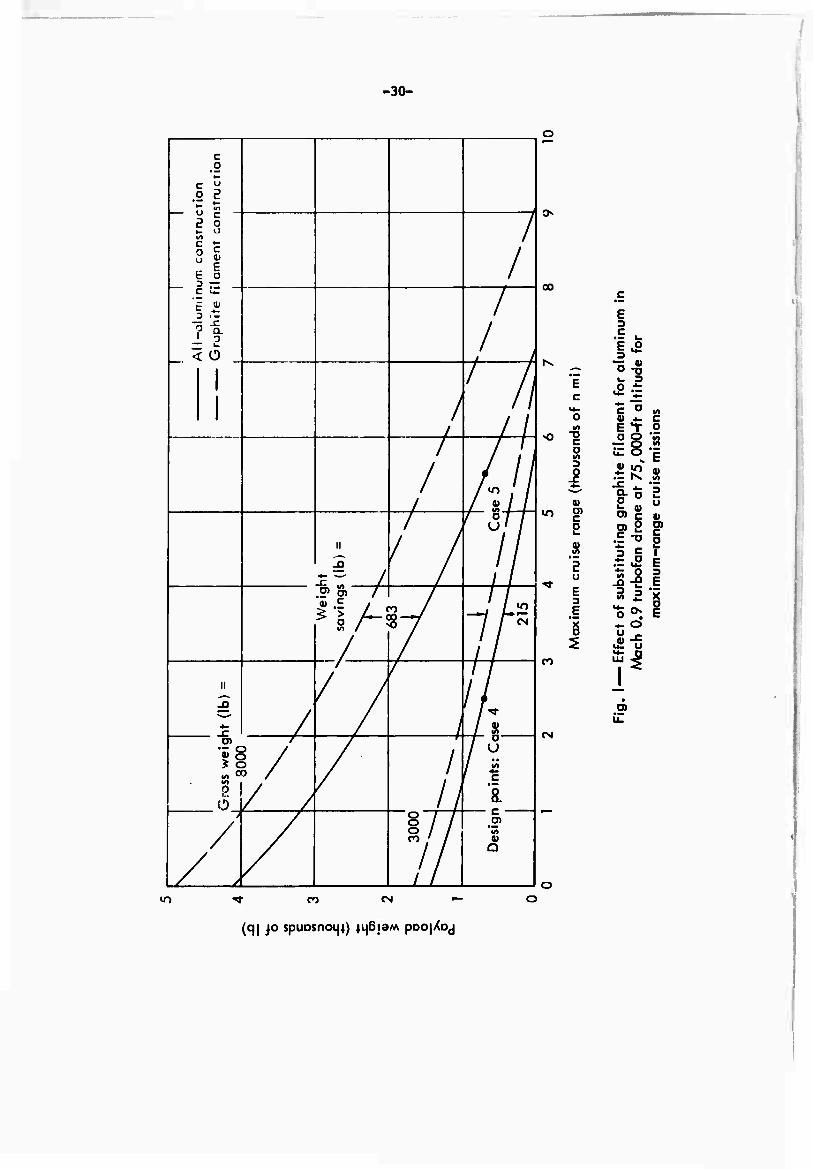
The weight saved by materials substitutions can be used to in-
crease the fuel capacity, thus Increasing endurance or range. This
effect can be illustrated by considering the use of graphite-filament
materials In Configurations 4 and 5. Curves of payload versus range
for aluminum drones of this type, i.e.. Mach 0.9 turbofans at 75,000 ft,
are presented in Fig. 1. The substitution of graphite-filament ma-
terials results in a weight saving of 215 lb for the 3000-lb all-aluminum
Or weight addition, in the case of the cast and molded plastics.
-29-
Table 14
WEIGHT REDUCTION FACTORS FOR VARIOUS MATERIAL COMBINATIONS FOR SUBSONIC DRONES
Structural Component Material Combination Fuselage Wing Talla Nacelleb
All fiberglass 0.85 0.90 0.85 0.85 Fiberglass - paper honeycomb 0.85 0.82 0.82 0.85 Cast and molded plastics 1.28 1,36 1.36 1.00 Paper and foam 0.93 0.81 0.81 1.00 Wood 0.88 0.90 0.90 1.00 Sall-wlng design 0.95 0.50 0.90 1.00 Graphite filament 0.75 0.60 0.75 0.75 Titanium 0.85 0.90 0.90 0.85
Tall weight is assumed to be 25 percent of the wing weight for the all-aluminum configuration.
Nacelle weight is assumed to be 7.5 percent of the engine weight.
c Not applicable for high-speed, low-altitude drones.
drone and 683 lb for the 8000-lb all-aluminum drone, thereby increasing
payload capability. Thus, a 3000-lb drone made from graphite-filament
materials, carrying a 700-lb payload, would have a range of about
3500 n ml, about 1000 n ml more than that of a 3000-lb all-aluminum
drone. And an 8000-lb graphite-fllament-materlals drone, with a
700-lb payload, would have a range of about 7300 n ml, about 1800 more
than that of the same-weight aluminum drone.
The weight savings can also be used to reduce vehicle size, power
plant, and required fuel capacity, all of which are Interrelated. This
has a multiplier effect on the original structural weight savings. The
additional weight reductions obtainable by resizing the vehicle have
not been examined here. However, they can be significant and should
be included in subsequent, more detailed investigations.
Tables 9 through 14 demonstrate the method used here to estimate
potential structural weight savings ifrom materials substitutions. Using
the basic materials data presented in Table 1 (along with any additional
information on these and other materials of Interest) and any design
method which is available for estimating structural component weights
\
-30-
)
1 *
c 0 IM
• u 2 2 • *-
1 2 8 in
I 8 | I E o 3 — _ c ^:
g •
- 2 L < o
/
/
/
/ ^
/ // /
/ / / - / /
n
1? /
/
/ /
/ /
/
*> /
8 /
/ /
H
4-
fit
1 e
/
/
/ / 'A
1/ [/ /
//
c
1 1
/
/
> 7/ .? 1 'in i
00
m
D C
1-2 ■s <u
*E J3 o ■•-
c •*• "Z V4- ^"ö VI o 4) f C
1 — S o
o in
5 E
8i 4- io 0)
c Is U 0)
2 o)2 .5 TJ
c n v c
Ul 3 C i
2 o
.^.2 E II 3 E
E 3 81 o
E E ^^ 8 *. o
U ^
CO
O)
CN
lO CO CN
(q| JO spuDsn044) 4i{6i3M pDOj/oj

-31-
for conventional aluminum construction, similar weight estimates can
readily be made for any other drone design or combination of structural
materials.
SUPERSONIC CRUISE VEHICLES
Considerably fewer structural materials are suitable for use In
supersonlc-crulse-vehlcle alrframes than In subsonic vehicles because
of the temperatures developed due to aerodynamic heating In supersonic
cruise flight. Three specific mission profiles will be conedered
here to indicate the severity of this aerodynamic heating. The per-
formance and characteristics of drones made from base-case materials
are given in Table 15.
Table 15
CHARACTERISTICS OF REPRESENTATIVE SUPERSONIC CRUISE VEHICLES SELECTED FOR ANALYSIS
Cruise Struc- Speed Cruise Cruise Gross Payload tural
Config- (Mach Altitude Range Weight3 Weight^ Weight3
uration No.) (ft) (n ml) (lb) (lb) (lb) Engine
6 2.3 75,000 1,150 6,000 700 644 Afterburning turbojet
7 3.0 75,000 950 6,000 700 745 Afterburning turbojet
8 5.0 120,000 1,000 8,000 700 2,117 Ramjet
Constructed from base-case materials: titanium alloys at Mach 2.3, graphlte/polyimide at Mach 3.0, and coated columblum alloys at Mach 5.0.
Includes guidance and navigation systems.
The structural material weight-estimating relationships contained
in the drone design model developed at Rand are based on a statistical
correlation of subsonic drone designs with conventional aluminum air-
frames. But for the Mach 5.0 configuration, a 50 percent increase
in structural weight was assumed, to reflect the lower mechanical
properties and higher densities typical of the high-temperature ma-
terials required. These assumptions were intended to provide a basis
■

-32-
for the analysis of materials possibilities presented here with respect
to the actual temperature environments encountered. The base-case ma-
terials for this analysis are titanium alloys (Mach 2.3), graphite/
polylmlde (Mach 3.0), and coated columblum alloys (Mach 5.0).
To obtain an estimate of the operating temperature ranges typical
of the three missions being discussed, representative bounding values
have been computed utilizing the following expression:
^M^-rV]
where T Is either the adlabatlc wall temperature, T In 0R, or the
stagnation temperature, T in 0R; T is the ambient air temperature
at altitude in 0R (T is 3950R at 75,000 ft and 4350R at 120,000 ft);
M is the local Mach number; R is the Prandtl recovery factor (R =
0.864 when computing T and 1.0 when computing T ); and y is the ratio 3 S
of specific heats, a constant equal to 1.4. The value of T is assumed 3
to be a representative lower bound. Indicating the average temperature
over a significant portion of the aerodynamic surface of the vehicle;
T is taken as an upper bound of the temperature range, representing s the local temperature on wing leading-edge surfaces, etc.
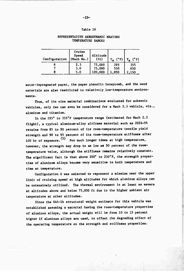
The computed values of T and T (converted to 0F) are given in 3 S
Table 16. The problem of materials selection for each of the three
supersonic vehicle airframes will now be individually considered on
the basis of these temperature-range estimates.
Mach 2.3 Flight
The mechanical properties of many of the materials that were
evaluated for subsonic cruise vehicles (where aerodynamic heating
is negligible) are seriously degraded at temperatures of only a few
hundred degrees Fahrenheit. These materials include, in particular,
the polyester and epoxy plastics which were suggested as matrix
materials for the filament-, chopped-fiber-, and fabric-reinforced
composite systems. Also Included in this group are the unreinforced
ABS molded plastic and the polyurethane foam. Obviously, the poly-
-33-
Table 16
REPRESENTATIVE AERODYNAMIC HEATING TEMPERATURE RANGES
Configuration
Cruise Speed
(Mach No.) Altitude
(ft) Ta (0F) T8 (0F)
6 7 8
2.3 3.0 5.0
75,000 75,000
120,000
295 550
1,850
355 650
2,150
ester-Impregnated paper, the paper phenolic honeycomb, and the wood
materials are also restricted to relatively low-temperature environ-
ments .
Thus, of the nine material combinations evaluated for subsonic
vehicles, only two can even be considered for a Mach 2.3 vehicle, viz.,
aluminum and titanium.
In the 295° to 3550F temperature range (estimated for Mach 2.3
flight), a typical aluminum-alloy alrframe material such as 2024-T4
retains from 85 to 90 percent of Its room-temperature tensile yield
strength and 90 to 95 percent of Its room-temperature stiffness after
100 hr of exposure. For much longer times at high temperature,
however, the strength may drop to as low as 50 percent of the room-
temperature value, although the stiffness remains relatively constant.
The significant fact is that above 200° to 250oF, the strength proper-
ties of aluminum alloys become very sensitive to both temperature and
time at temperature.
Configuration 6 was selected to represent a mission near the upper
limit of cruising speed at high altitudes for which aluminum alloys can
be extensively utilized. The thermal environment Is at least as severe
at altitudes above and below 75,000 ft due to the higher ambient air
temperature at other altitudes.
Since the 644-lb structural weight estimate for this vehicle was
established assuming a material having the room-temperature properties
of aluminum alloys, the actual weight will be from 10 to 15 percent
higher if aluminum alloys are used, to offset the degrading effect of
the operating temperature on the strength and stiffness properties.

-34-
At room temperature, the typical titanium airframe alloys, e.g.,
Ti-6A1-4V and Tl-6Al-6V-2Sn, are about 60 percent stlffer than the
aluminum alloys, but also about 60 percent heavier. Thus, there is
little advantage to be gained by substituting titanium for aluminum
for stiffness-critical components. However, the typical strength
properties of titanium are at least three times higher than those for
aluminum, resulting in a specific strength about twice as high. There-
fore, weight savings of 10 to 15 percent are possible, through the
substitution of titanium for aluminum (see Table 1). However, the
titanium alloys suffer about the same strength and stiffness losses in
the 295°F to 3550F temperature range as the aluminum alloys, the
Ti-6Al-6V-2Sn alloy having a slightly better strength retention.
Thus, a titanium airframe designed for the 2950F to 3550F tempera-
ture environment can be expected to weigh about the same as an aluminum
airframe designed for room-temperature conditions. That is, for Con-
figuration 6, an aluminum airframe would weigh about 15 percent more
than a 644-lb titanium airframe.
Steel alloys are also candidate materials. An alloy such as
Type 301 stainless steel (Fe-18Cr-8Nl) would result in a structural
weight comparable to that of titanium.
There is one additional group of materials, represented by the
graphlte/polylmide composites included in Tables 1 through 7, which
have a much higher potential for supersonlc-flight environments,
however. These are the high-temperature polymer matrix composites, of
which the polyimldes are currently the best known. Recent work has
indicated good strength and stiffness retention of polylmide matrix
composites after long exposures at 600oF. ' These high-temperature
polymers were not considered for the subsonic-flight vehicles, since
temperature was not a consideration. They are not yet as well-developed
as the epoxies and are presently slightly more expensive and difficult
to work with.
When used with any of the reinforcements included in Table 1, the
polyimldes offer composite strength and stiffness properties at least
as high as those of the epoxies. And the densities are about the same.
Hence, the weight savings for epoxy matrix composites at room temper-
ature, indicated in Table 1, can be taken as the weight savings for

-35-
polylmide matrix composites In the 295°F to 3558F temperature environ-
ment of Configuration 6. Obviously, these high-temperature polymers
have the same high potential for revolutionizing the construction of
supersonic vehicles as the room-temperature polymers are presently
demonstrating for subsonic vehicles.
Mach 3.0 Flight
In the 550oF to 650oF temperature range that would be encountered
by Configuration 7, the aluminum alloys retain only 10 to 30 percent
of their room-temperature strength. Thus, they must be eliminated
from practical consideration.
The titanium alloys retain about 70 to 75 percent of their room-
temperature strength at these temperatures, and about 80 percent of
their room-temperature stiffness. Since, as Indicated In Table 1
and discussed for Configuration 6, the titanium alloys offer a 10 to
15 percent weight savings (relative to aluminum) for room-temperature
applications, a titanium alrframe designed for the 550oF to 650oF
temperature environment of Configuration 7 can be expected to weigh
from 10 to 20 percent more than the 745-lb base-case alrframe.
As for Configuration 6, steel alloys such as Type 301 stainless
will result In a structural weight very close to that for titanium—
slightly higher because of the lower specific strength of the steel
alloys.
The polylmlde matrix materials, discussed for Configuration 6,
were Indicated to have good strength and stiffness retention after
long exposures at 600oF. Limited data available to date Indicate the
following strength-retention percentages when the composites were
tested at 600oF after 500 hr exposure at 600oF: %.«.(«)
E glass-fabrlc/polylmlde—65 percent
S glass-fllament/polylmlde—40 percent
Graphite-fllament/polylmlde—75 percent
All three composites have similar densities. The S glass-filament/
polylmlde composite Is about three times as strong as the E glass-
fabric polylmlde at room temperature and hence Is still twice as
- - _— ., .,■.■..«.,„,. .— ■ —. .— —

-36-
strong at 600°F, even though it suffers a greater degradation. Like-
wise, having a higher room-temperature strength than the graphite-
filamfnt/polyimide, it has a comparable strength at 600oF. However,
the stiffness of the high-modulus graphite-filament-reinforced polyim-
Ide composite remains about five times greater \han that of the S
glass-filament-reinforced polyimide, the stiffness being less sensi-
tive to temperature than the strength.
In summary, the E glass-fabric/polylmide composite is not a likely
candidate for primary airframe components at Mach 3.0, being only about
one-half as strong and stiff as the S glass-filament/polyimlde compos-
ite. However, as Table 1 and previous discussion indicated, E glass
is less expensive than S glass (although both are relatively low-
cost materials), and therefore it may be useful for lightly loaded com-
ponents such as fairings or access covers.
For strength-critical components, the S glass-filament/polyimlde
composite offers equal performance and is much less expensive than the
graphite-filament/polyimide composite. For stiffness-critical compo-
nents, the graphite-filament/polyimide material is five times better—but
more than four times as expensive. Thus, it is necessary to determine
the value of a pound of weight saved. However, if the cost of graphite
filaments is greatly reduced during the next few years, as predicted,
the graphite-filament-reinforced polyimide will clearly be the better
material to use.
As previously pointed out, aluminum is not a practical material
for a Mach 3.0 vehicle. Fortunately the graphite-filament/polyimide
composites provide adequate strength at Mach 3.0 and result in a vehicle
weight about equal to that given in Table 15. Hence, the data of
Table 15 for Mach 3.0 flight should be interpreted as applying for
vehicles constructed of materials equivalent to graphite-filament/
polyimide.
The temperatures developed during Mach 3.0 flight are very nearly
the maximum allowable for the polyimides, and Configuration 7 repre-
sents a limiting case for this type of material. Other high-temperature
polymers are currently being investigated, however, and while few
actual results are presently available, it appears that operating
temperatures as high as 1000°F will be attainable.

.
-37-
Mach 5.0 Flight
The 1850oF to 2150oF thermal environment associated with Con-
figuration 8 automatically eliminates the aluminum alloys and the
high-temperature polymer matrix composites from consideration, because
of their temperature limits (defined in the discussion of Configuration
7).
The titanium alloys and the stainless steels both lose strength
and stiffness very rapidly above 800°F and are also eliminated from
consideration for the temperature environments of Mach 5.0 flight.
Beryllium alloys and iron-chromium-nickel-base alloys are inadequate
above about 800oF and 1200oF, respectively.
Nickel is the base element for most of the heat-resistant super-
alloys that even approach the temperature range of Mach 5.0 flight.
These materials, of which Hastelloy X and Ren^ Al are well-known ex-
amples, are typically limited to applications in the 1200°F to 1500°F
range. The cobalt-base alloys are only slightly more heat-resistant,
extending the upper limit to about 1800oF.
However, one particular nickel-base material consisting of thoria
dispersed in a nickel matrix (commonly referred to as TD nick >.l) does
have good stability at 1850oF to 2150oF, although its mechanical prop-
erties are poor. For example, its room-temperature yield strength and
stiffness are about 55,000 psi and 17 x 10 psl, respectively; at
2000oF they drop to about 15,000 psi and 8 x 10 psl, respectively.(
The yield strength of TD nickel at 2000oF is about 40 percent that of
an aluminum alloy at room temperature; the stiffness is about 75 per-
cent that of an aluminum alloy at room temperature. Also, the density
of TD nickel is about 3.2 times that of an aluminum alloy.
Thus, the 2117-lb structural-weight estimate for the base case
(which is 50 percent higher than would be predicted if an aluminum
alloy operating at room temperature were assumed) would have to be
multiplied by an additional factor of about A if TD nickel were used
for Configuration 8. Obviously TD nickel is not a practical material
for this vehicle.
The columblum alloys are more suitable materials than TD nickel
for Configuration 8. To avoid surface embrittlement and scaling at
^ . ■ , i
t X

-38-
hlgh temperatures, the columblum alloys are almost always used with a
protective coating—hence, the designation, "coated columblum." A wide
range of columbium alloys are available. A typical high-strength alloy
such as Cb-15W-5Mo-lZr has a yield strength of about 50,000 psl at
2000oF, and a stiffness of about 18 x 106 psl.(7^ This yield strength
is about 40 percent higher than that of an aluminum alloy at room
temperature; the stiffness is about 70 percent higher. The density of
the columbium alloy is only slightly higher than that of TD nickel.
Thus, the 2117-lb structural-weight estimate for the base case
could be considered as generally representative of an alrframe utilizing
a columbium alloy extensively.
The molybdenum alloys such as Mo-0.5T1 are somewhat comparable
to the columbium alloys, being about 60 percent stlffer at 2000oF
(29 x 10 psi), but having a 20 percent lower yield strength (about
40,000 psi) and a 10 percent higher density. The net effect of
using a molybdenum alloy for Configuration 8 would also be an alrframe
weight in the general range of the 2117-lb estimate—perhaps slightly
less because of the better stiffness properties of molybdenum alloys.
Because the stiffness of these alloys at 2000oF Is unusually high, a
detailed component-by-component comparative evaluation would be re-
quired to obtain a more accurate weight estimate.
Summary
The comparisons of materials for the three supersonic-cruise-
vehicle configurations are summarized in Table 17. Finished-part
cost ratios similar to those glv^n in Table 1 are also presented.
Reductions in structural weight relative to the base cases can be
achieved at Mach 2.3 (roughly 15 to 25 percent) by using S glass/polylmlde
composites and graphlte/polyimide composites and at Mach 5.0 (roughly 10
percent) by using coated molybdenum alloy. There was no material that
gave improvement at Mach 3.0 over the base case (utilizing graphite/
polyimlde) among the materials investigated.

-39-
0) H
•a
&
*J w ID a o 0 u o
U-l u u DM h
as ID 3 PM O PL, OCMIHNIH vom 00
•H W [»•••• •• «1
« <u 3 pi JZ a
HtMi-HrHCM CMCg H
3 s s ^
r\ o •
9) m ^^^>^^/-S^^ ^N O ^> 1 to 00 gjcdididid *PiH idl a o JS s«> ^-^ ^/>-* v^ s»* | s^ 1 «3 iH o 6 5 1 bs ^~" tl § ^N 0» -^ •H o a « w 4J •
n C cd CO ^^moo^^ mo o rj « 0) r^ Id rH <N \0 43 «*CNJ VO « PQ U ; 3 A ^-' ^^ H
UH M ÖC o 9 O 01 •H i 4J 4J P. ü ^
IM 9
9 0) \u > 5 '
4J -H CO 4J ^N
CO <n iH iH • " Ü <M 4J em vo m/-\iriin«o mo ol 0 A H ^ H N <M tH O I H U 1 ^ 1 1 H
/-\ ( 9 1 M 09 CM ^ (D 0) /^
41 1 « 01 4J ^H l > n 4J «H H ; /-sxo o) -H n m i
H
24-T4
-6A1-
tainl
ompos
compo
loys
Mo-O.
rkel
)
H «J
■H M O-HUU r-l '•-'1-110
M EH OJ Cd ^S 9 -H 0) « ^"^H 01 -O MB U \
I Oxl'rtaN>s'00 nn<n<Ha9«Hoo)j3 >% ^^^ a «H -H 1 iH (0 4J
■3
allo
allo
loys
polyl
/poly
olumb
W-5Mo
urn al
Isper
cent
^ 9 « s aaH^o)üm9'OW
9 3 id « 4J MO) oi M 9-H W -H TJ 1 -O 10 (X " ■HgHCdiSOiai^l'H
aidoifHawu^hcs 9« o) ooojio^-'i-t o^
(0
1 ^SÄWÖ3 i£ |
■ •H
• M 0) 0) H *J J3 «0 « a u
-H 0) iH 0) a B) p, u 10 I
0) *J (0 o a
js « 9 .O
|
1
I i
i a 0)
0) 9
1 01 >
id
01 9

-41-
REFERENCES
1. Drone configuration design data provided by T. F. Klrkwood, The Rand Corporation.
2. Pazmany, L., Potential Structural Materials and Design Concepts for Light Aircrafts San Diego Aircraft Engineering, Inc., NASA Contractor Report NASA-CR-1285, March 1969.
3. Price, A. B., J. A. Heinrichs, and E. J. Tanner, Low Cost Airfram Design Studies for an Expendable Air-Launahed Cndse Vehiole, Martin Marietta Corporation Report No. ER 14920, April 1970.
4. Air Force Materials Laboratory, Advcmoed Composites Status Review- Proceedings t Collection of papers presented at West Palm Beach, Florid«, September 30 - October 2, 1969.
5. Metallic Materials and Elements for Aerospace Vehicle Structures, MIL-HDBK-5A, February 1966.
6. Browning, C. E., and J. A. Marshall, II, "Graphite Fiber Reinforced Polyimlde Composites," Journal of Composite Materials, Vol. 4, July 1970, pp. 390-403.
7. Aerospace Structural Metals Handbook, Vclume II-A, "Non-Ferrous Heat Resistant Alloys," Mechanical Properties Data Center, Traverse City, Michigan, 1969.