airgoggle nvc210wd
TRANSCRIPT
NVC210R2 and NVC210WD User’s Guide
`
Rev0.1(Aug. 2009)
AirGoggle NVC210R2
AirGoggle NVC210WD USER’S MANUAL Rev 0.1 August 2009
Corporate Headquarters
Inscape Data Corporation
1611 South Main Street
Milpitas, CA 95035
USA
http://www.inscapedata.com
Tel: 408 935-8500
1-888-267-4507
Fax: 408 935-8900

NVC210R2 and NVC210WD User’s Guide
Rev.0.1 (Aug. 2009) 2222 of 56 of 56 of 56 of 56
FCC Notice NOTE: This equipment has been tested and found to comply with the limits for a Class A digital device,
pursuant to part 15 of the FCC Rules. These limits are designed to provide reasonable protection against harmful
interference in a residential installation. This equipment generates, uses, and can radiate radio frequency
energy and, if not installed and used in accordance with the instructions, may cause harmful interference to radio
communications. However, there is no guarantee that interference will not occur in a particular installation. If this
equipment does cause harmful interference to radio or television reception, which can be determined by turning
the equipment off and on, the user is encouraged to try to correct the interference by one or more of the following
measures:
• Reorient or relocate the receiving antenna.
• Increase the distance between the equipment and receiver.
• Connect the equipment into an outlet on a circuit different from that to which the receiver is connected.
• Consult the dealer or an experienced radio/ TV technician for help.
Changes or modifications not expressly approved by the party responsible for compliance could void the user’s
authority to operate the equipment. The manufacturer is not responsible for any radio or TV interference caused
by unauthorized modifications to this equipment. Such modifications could void the user’s authority to operate the
equipment.

NVC210R2 and NVC210WD User’s Guide
Rev.0.1 (Aug. 2009) 3333 of 56 of 56 of 56 of 56
Important Manufacturer Notes
• NVC210R2 and NVC210WD are designed for indoor use. When using NVC210R2 and NVC210WD
in an environment that exceeds the equipment normal operating range, environmental
enclosures must be used.
• Do not drop or mechanically shock the equipment. Doing so will void related manufactures
warranty.
• Please keep the device out of reach of children.
• Disassembling the product will voice your manufactures warranty.
• Use only the power adapter provided with the NVC210R2 and NVC210WD. Using improperly
rated power supply may hinder the performance or specification of the equipment.
• Please check with your regulatory authority on security video or audio surveillance prior to If you
would like to use the NVC210R2 and NVC210WD for security, monitoring, please check the legal
regulations within the country.

NVC210R2 and NVC210WD User’s Guide
Rev.0.1 (Aug. 2009) 4444 of 56 of 56 of 56 of 56
1. Introduction...............................................................................................................................................5
1.1. Product Summary......................................................................................................... 5
1.2. Features ......................................................................................................................... 6
1.3. Applications ................................................................................................................... 7
2. Product Description ..................................................................................................................................8
2.1. Package Contents ......................................................................................................... 8
2.2. CDROM Software Contents .......................................................................................... 8
2.3. System Dimension and Interface................................................................................ 9
2.4. PC Minimum Requirement ......................................................................................... 11
2.5 Quick Installation Guide.............................................................................................. 11
3. Connecting NVC210R2 and NVC210WD to Network .........................................................................16
3.1. Connecting to LAN ...................................................................................................... 16
3.2. Connecting to xDSL/Cable Modem ........................................................................... 17
4. IP-Installer...............................................................................................................................................19
4.1. Main window of IP-Installer ....................................................................................... 19
5. Configuring NVC210R2 and NVC210WD in Administrative Mode ....................................................21
5.1. Log On ......................................................................................................................... 21
5.2. Basic Setup ................................................................................................................. 23
5.3. Network Configuration ............................................................................................... 25
5.4. Wireless Configuration ............................................................................................... 28
5.5. CCD Adjustment ......................................................................................................... 30
5.6. User Admin & Time Setup ......................................................................................... 32
5.7. Sensor & Capture Setup ............................................................................................ 35
5.8. Alarm Device Setup.................................................................................................... 37
5.9. Motion Region Setup .................................................................................................. 39
5.10. PTZ Setup(Zoom is not applicable for NVC210R2 and NVC210WD) .................. 41
5.11. Encryption Set up ..................................................................................................... 43
5.12. Upgrade & Reset....................................................................................................... 45
5.13. Status Report ............................................................................................................ 47
6. Tips for using NVC210R2 and NVC210WD..........................................................................................48
6.1. ALARM-IN and ALARM-OUT ....................................................................................... 48
6.2. Trouble Shooting......................................................................................................... 51
6.3. Web Viewer ................................................................................................................. 52
6.4. How to Upgrade the NVC210R2 and NVC210WD.................................................... 54
Table of Contents

NVC210R2 and NVC210WD User’s Guide
Rev.0.1 (Aug. 2009) 5555 of 56 of 56 of 56 of 56
1. Introduction
1.1. Product Summary
The AirGoggle™ NVC210R2 and NVC210WD are all-in-one high-performance professional fixed day
and night IP surveillance cameras. Both come standard with an auto-iris vari-focal lens. The
NVC210R2 and NVC210WD camera delivers crisp full D1 high quality MPEG-4 full motion real-time
video across an IP network. The convenient option of IEEE 802.3af Power over Ethernet enables
power and data over a single network cable. The NVC210R2 and NVC210WD network cameras have
a compact aluminum bodies for installation onto vertical or horizontal mounting surface. When
used for outdoor surveillance, a wide selection of complementary camera housing accessories and
lenses are available. High performance and reliable design, along with a host of convenient features,
makes the AirGoggle™ NVC210R2 and NVC210WD cameras ideal for indoor or outdoor*
professional security surveillance applications.
The NVC210WD model with wide dynamic range has an added benefit of digital pixel technology.
Wide dynamic range tackles severe backlight and glare issues by dynamically compensating
contrast to deliver uniform steady clear video images. The digital pixel technology brings true
digital performance throughout the entire real-time encoding process from the moment an object is
captured through the lens to the encoded images across the network. The synergy of these two
enhancement technologies brings forth the best signal to noise and low light sensitivity in its class
for the most demanding video surveillance applications.

NVC210R2 and NVC210WD User’s Guide
Rev.0.1 (Aug. 2009) 6666 of 56 of 56 of 56 of 56
1.2. Features
Feature Description
Wide Dynamic Video Technology
Available with NVC210WD to ensure details of high contrast scenes to
appear clear with accurate color in both bright and dark areas
simultaneously.
IEEE 802.3af
Power over Ethernet (PoE)
IEEE 802.3af PoE injection eliminates power connection at the camera
location. The convenience of running a single network cable eliminates the
need for power sources near the camera
IR Sensitive True Day and
Night Functionality
Removable infrared-cut filter provides color video when there is sufficient
light and black & white video in dark environments. The high performance
image sensor is IR sensitive for pitch black operation when used with an
infrared illuminator
High Quality Full Motion IP Video
Codec
Stream full motion D1 720 x 480 live color video images across a local or
wide area network. Network connected computers can monitor, record, and
playback security video with ease
Multi-Region Motion Detection
Increase motion sensitivity in multiple regions you specify or mask areas
where motion is allowed for precise motion detection control
MPEG4 + JPEG Streaming Dual Streaming for mobile WAP network
Embedded Streaming Web Server
The suite of function from the embedded streaming web server makes
accessing real-time video easy from any Internet Explorer enabled computer
Event Driven Real-Time
notification
The integrated sensor input, alarm output, and video motion detection
provides actionable event trigger capable of ending a video clip via email or
FTP and turn on/off external relays
Synchronized Audio/Video and
Two-Way Audio Communication
Audio line in and line out interface(s) with software selectable audio features
provide synchronized audio surveillance and announcement capabilities from
the monitoring station
Full Featured 64 Channel
professional Network Video
Monitoring and Recording
Software
Included with this product purchase is a licensed copy of 64 channel full
featured network video monitoring and recording software for Windows PC.
User will be able to manage alarms, trigger relays, enable two-way audio
Communication, schedule recording, setup alarm recording, playback pre-
recorded video, user selectable video storage location, and much more.

NVC210R2 and NVC210WD User’s Guide
Rev.0.1 (Aug. 2009) 7777 of 56 of 56 of 56 of 56
1.3. Applications

NVC210R2 and NVC210WD User’s Guide
Rev.0.1 (Aug. 2009) 8888 of 56 of 56 of 56 of 56
2. Product Description
2.1. Package Contents
1. Camera Body
2. Lens Auto-Iris Varifocal Lens 3.5 ~ 8mm (CS Mount)
3. Lens Adapter C to CS Mount
4. DC Iris Lens Connector Kit
5. Back Focus Adjustment Allen Wrench (L shaped wrench)
6. Switching Power Supply 12VDC 1.5A
7. AC Power Cable
8. Swivel Arm Surface Mount Bracket with screws
9. Product CDROM
2.2. CDROM Software Contents
ItemItemItemItem DescriptionDescriptionDescriptionDescription
NVR100 16 Channel Viewer Software
NVM1000 64 Channel Video Monitoring, Recording, and Management Software
IP Installer Software IP Configuration Software For the Equipment
User Manual NVR100, NVM1000, IP Installer, and This Users Guide
Application Note Firewall, IP Sharing, and Related User Notes.
PTZ Driver Supported 3rd Party CCTV PTZ Camera Drivers
Warranty Manufacturers Warranty Information

NVC210R2 and NVC210WD User’s Guide
Rev.0.1 (Aug. 2009) 9999 of 56 of 56 of 56 of 56
2.3. System Dimension and Interface
Actual Image of ProductActual Image of ProductActual Image of ProductActual Image of Product

NVC210R2 and NVC210WD User’s Guide
Rev.0.1 (Aug. 2009) 10101010 of 56 of 56 of 56 of 56
InterfaceInterfaceInterfaceInterface Description Description Description Description
No. Interface Description
1 Auto-Iris Connector For use with DC based Auto-Iris Lens
2
CS Lens Mount Ring Lens Mount Interface For CS Type Lens. To Use C Type Lens, a
CS to C Type Lens Adapter is Needed.
3 Audio Line Out 3.5 mm 3 conductor mini-jack external
speaker or PA system interface.
Standard 3.5mm stereo jack and
amplified speakers are needed. The
electrical connection notes are noted
in the jack image to the right.
4 Audio/MIC In 3.5 mm 3 conductor mini-jack external
Audio Line In or Microphone Input
interface. A standard 3.5mm stereo
jack is needed. The electrical
connection notes are noted in the jack
image to the right.
5 RJ45 Jack 10/100 Base-Tx Network Interface with IEEE 802.3af Power Over
Ethernet Capability
6 Hardware Reset Pin Restore to factory default configuration. There is a switch provided
for returning the network camera to factory default state. Press the
switch through a tiny hole at the left of the 100BaseT connector
using tools with sharp tip for a few seconds while power is applied.
7 Power Connector Local 12VDC power input. Do not use local power connector when
PoE is used.
8 Relay Output Connector
(RLY OUT)
Controls 1 set of dry contact relay. The relay can be set to
normally open or normally closed contact.
9 Alarm / Sensor Input
Connector (SNS IN)
Attached 1 set of dry contact sensor into the alarm/sensor input
connector to trigger recording or relay output. Most common
sensors are infrared sensor, heat sensor, magnetic sensor, etc.
Please refer to Section 6.1 for more detailed description on the
Alarm In/Out connections.
10 RS-485 Connector Output PTZ control to PTZ modules. Inscape Data cameras support
over 30 PTZ protocol drivers. Drivers maybe found on the product
CD-ROM and uploadable to the IP camera via the web management
Audio out
GroundNot used
Audio out
GroundNot used
Audio In
GroundNot used
Audio In
GroundNot used

NVC210R2 and NVC210WD User’s Guide
Rev.0.1 (Aug. 2009) 11111111 of 56 of 56 of 56 of 56
interface.
11 Composite Video Out
(CVBS +/-)
Analog video output signal with 1 V p-p.
12 Not Used Not Used
13 Factory Use Factory Use Only
14 Network Link/ Activity
Indicator
-Link LED: Continuous yellow light means that network cable is
plugged in. It will flicker when there is traffic.
- Status LED: Green color indicates that the camera is in normal
operation mode, while RED color indicates that the camera is in
abnormal condition.
Not
Shown
Integrated Microphone Built in Microphone located at the front of the camera
2.4. PC Minimum Requirement
AV streaming data received from NVC210R2 and NVC210WD can be decoded or stored in a PC
running NVR100 or NVM1000 program which is a viewing & recording program for a PC. Minimum
requirement of the PC is described below:
Minimum Recommended
CPU Pentium III 700 Pentium IV 1.2G above
Main Memory 128 MB 256MB above
Operating system* Windows 2,000 or later Windows 2,000 or later
Web browser Internet Explorer 5.0 Internet Explorer 5.0 above
Resolution 1,024 X 768 Higher than 1,024 X 768
Network 10 Base-T Ethernet 100 Base-T Ethernet
* Operating Systems supported : Windows 2000 Professional
Windows XP Professional / Windows XP Home Edition
2.5 Quick Installation Guide
Brief information for rapid installation is provided in this section. For more detailed information you
are recommended to refer to pertinent documentations provided with the product or refer to
Inscape Data’s home page (http://www.Inscape Data.com)

NVC210R2 and NVC210WD User’s Guide
Rev.0.1 (Aug. 2009) 12121212 of 56 of 56 of 56 of 56
1. Connect NVC210R2 and NVC210WD to LAN by using one of the following method
1) If your NVC210R2 and NVC210WD has standard PoE option, connect the network camera
and PC as illustrated in Figure 2.4. Both power and network connections are made with a
single LAN cable. Make sure that you are using hub supporting standard PoE (802.3af).
2) If your NVC210R2 and NVC210WD does not support standard PoE or you don’t have hub
supporting standard PoE, connect NVC210R2 and NVC210WD as in Figure 2.5. The DC
power is applied through AC adaptor.
2) If you have standard power connect the network camera and PC as illustrated in Figure
2.6.
Figure 2-4. Connecting Network camera using Standard PoE (802.3af).
Figure 2-5. Conventional way of connecting network camera without standard PoE.
AC Adaptor
Hub
AC In
100BaseT
DC In
Standard PoE Hub
NVC210R2 and NVC210WD User’s Guide
Rev.0.1 (Aug. 2009) 13131313 of 56 of 56 of 56 of 56
<Caution>
When power is applied through standard PoE, never apply power through AC
adaptor. Inscape Data assumes no responsibility for the damages caused by
collision of the power through the standard PoE and AC adaptor.
2. Install “IP installer” and “NVR100 or NVM1000” on your PC.
Detailed information for installing these programs can be found in [IP-Installer User’s
Guide] and [NVR100 or NVM1000 User’s Guide], respectively.
3. Assign IP address to NVC210R2 and NVC210WD using IP installer.
Identify the type of the network environment and set up IP address. Detailed process of
setting up IP address can be found in [IP-Installer User’s Guide]. If network type is
xDSL or Cable modem you need supplementary information provided by your ISP.
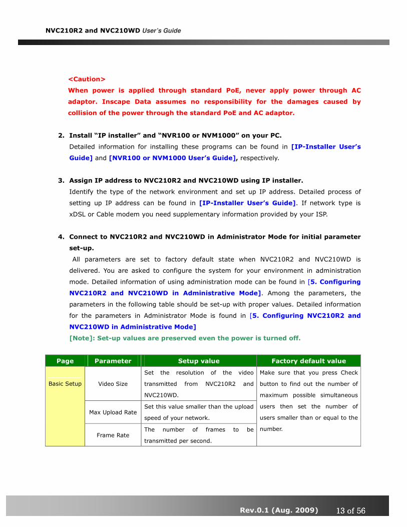
4. Connect to NVC210R2 and NVC210WD in Administrator Mode for initial parameter
set-up.
All parameters are set to factory default state when NVC210R2 and NVC210WD is
delivered. You are asked to configure the system for your environment in administration
mode. Detailed information of using administration mode can be found in [5. Configuring
NVC210R2 and NVC210WD in Administrative Mode]. Among the parameters, the
parameters in the following table should be set-up with proper values. Detailed information
for the parameters in Administrator Mode is found in [5. Configuring NVC210R2 and
NVC210WD in Administrative Mode]
[Note]: Set-up values are preserved even the power is turned off.
Page Parameter Setup value Factory default value
Video Size
Set the resolution of the video
transmitted from NVC210R2 and
NVC210WD.
Max Upload Rate Set this value smaller than the upload
speed of your network.
Basic Setup
Frame Rate The number of frames to be
transmitted per second.
Make sure that you press Check
button to find out the number of
maximum possible simultaneous
users then set the number of
users smaller than or equal to the
number.

NVC210R2 and NVC210WD User’s Guide
Rev.0.1 (Aug. 2009) 14141414 of 56 of 56 of 56 of 56
Video Rate
Bandwidth assigned for video
transmitted from NVC210R2 and
NVC210WD.
User Admin
& Time
Setup
Administrator
name &
password
For safety, you are recommended to
change these values from factory
default. For new connection, you need
to input changed values for
corresponding fields. Do not disclose
these values to others and memorize
these values.
Default value
Username : root
Password : root
User Admin
& Time
Setup
Current Time
Input correct time in this field. Default value :
2001/1/1
5. Connect the input and output signals to NVC210R2 and NVC210WD.
Connectors Function Signal description Number
LINE-
In/MIC Audio in
Connect microphone or output from
audio devices. 1
Line Out Audio out for
speaker
Audio from remote site is available
from this connector in bi-directional
audio mode. Connect speaker with
amplifier.
1
SENS IN Connecting
Alarm Sensor
IR sensor, Motion Sensor, Smoke
Detector… 1
RLY OUT
Connecting
Alarm
annunciating
device
Siren, Flashing Light, … 1
RS485 PT device control Remote P/T/Z device connection
having RS485 interface. 1
100Base-T
802.3af
Network
connection
Connect NVC210R2 and NVC210WD to
the network, LAN, ADSL or Cable
modem.
1
CVBS OUT Analog Video Composite video output from the 1

NVC210R2 and NVC210WD User’s Guide
Rev.0.1 (Aug. 2009) 15151515 of 56 of 56 of 56 of 56
output camera module.
6. Remote video connection to NVC210R2 and NVC210WD
Run NVR100 or NVM1000 on your PC. Before connecting to NVC210R2 and NVC210WD it
is needed to configure the connection information on the NVR100 or NVM1000. More
detailed information of using “NVR100 or NVM1000” can be found in [NVR100 or
NVM1000 User’s Guide].

NVC210R2 and NVC210WD User’s Guide
Rev.0.1 (Aug. 2009) 16161616 of 56 of 56 of 56 of 56
3. Connecting NVC210R2 and NVC210WD to Network
NVC210R2 and NVC210WD supports LAN, xDSL, and Cable modem. It also supports shared IP
environment where single IP address is shared by at least 2 IP devices. Refer to [IP-Installer
User’s Guide] for details of setting the IP address for NVC210R2 and NVC210WD.
3.1. Connecting to LAN
In case of connecting the NVC210R2 and NVC210WD to LAN, it is generally connected as in
Figure 3-1.
Figure 3-1. Connecting the NVC210R2 and NVC210WD to LAN
1. Follow through steps 1 to 3 in Section 2.5 to assign IP address to NVC210R2 and NVC210WD.
2. Install NVC210R2 and NVC210WD and connect it to desired LAN.
3. Check if you can receive video data when connecting to NVC210R2 and NVC210WD using the
viewer program.
4. When one or more IP video products are connected through a IP sharing device (i.e. router) to a
larger network (i.e. the internet), in order to access each unit from outside the local area network,
each device must have a unique RTSP (Real Time Stream Protocol) and HTTP port number. You
must also configure your IP sharing device for “port forwarding”. This is to enable the IP sharing

NVC210R2 and NVC210WD User’s Guide
Rev.0.1 (Aug. 2009) 17171717 of 56 of 56 of 56 of 56
device to forward packet data with unique port number (RTSP and HTTP) to unique internal IP
address (local IP address). If you only plan to access multiple units from within a local area
network, you do not need to change the RTSP and HTTP port numbers, unless other IP sharing
devices sit in-between the client and the IP video products. For more detailed information
regarding the use of IP sharing device refer to the document [Use of Private IP network using
IP-sharing-device].
3.2. Connecting to xDSL/Cable Modem
1. Follow through steps 1 to 3 in Section 2.5 to assign IP address and other network parameters to
NVC210R2 and NVC210WD.
2. Install NVC210R2 and NVC210WD and connect it to xDSL or Cable modem as in Figure 3-2.
Figure 3-2. Connecting the NVC210R2 and NVC210WD to ADSL Modem
When fixed IP address is assigned to the xDSL or Cable modem, follow the same way as
assigning IP address for the case of LAN using IP-installer. To enable the notification of the
changed IP address to the user over e-mail when the IP address is changed in floating IP
environment, you have to assign the e-mail address when user name and password are
input using IP-installer. (Management server provides a convenient way of
connecting to your network camera under dynamic IP environment. Please refer
②②②②

NVC210R2 and NVC210WD User’s Guide
Rev.0.1 (Aug. 2009) 18181818 of 56 of 56 of 56 of 56
to the Application note regarding “Management Server” in the CD.)
When connecting NVC210R2 and NVC210WD to xDSL or Cable modem, usually regular
LAN cable is required. But since some modems have crossover connections, please
contact your service provider for detailed information.

NVC210R2 and NVC210WD User’s Guide
Rev.0.1 (Aug. 2009) 19191919 of 56 of 56 of 56 of 56
4. IP-Installer
NVC210R2 and NVC210WD needs IP network parameters for connection to the
network(Internet/Intranet). IP-Installer is a PC program for the initial network configuration to IP
video products such as Network Camera or A/V Server. IP-Installer is provided in a CD supplied
with NVC210R2 and NVC210WD or it can be downloaded from “www.Inscape Data.com”.
Detailed information of Installing and running IP-installer can be found in [IP-installer
user’s guide]
4.1. Main window of IP-Installer
Figure 4-1. IP Installer

NVC210R2 and NVC210WD User’s Guide
Rev.0.1 (Aug. 2009) 20202020 of 56 of 56 of 56 of 56
All the basic network parameters needed for the initial connection to IP video products can be
assigned by IP-Installer. Once the basic parameters are assigned and the initial connection is
successfully made, you can connect to the administration page for more sophisticated control of
the network parameters and other operational parameters. Refer to Chapter 5 for more details of
the administration page.
NVC210R2 and NVC210WD User’s Guide
Rev.0.1 (Aug. 2009) 21212121 of 56 of 56 of 56 of 56
5. Configuring NVC210R2 and NVC210WD in
Administrative Mode
5.1. Log On
There are 2 ways of connecting to NVC210R2 and NVC210WD administrative mode. One is through
Internet Explorer and the other is through “NVR100 or NVM1000” program.
1. Using Internet Explorer
Type in the connection address of the network camera in the address window of the Internet
Explorer as followings:
http://[NVC210R2 and NVC210WD IP address]/admin.htm
Example: http://192.16.64.133/admin.htm
If you changed the HTTP port from default value you can login by typing in:
http://[NVC210R2 and NVC210WD IP address]:[HTTP port]/admin.htm
Example: http://192.16.64.133:8080/admin.htm
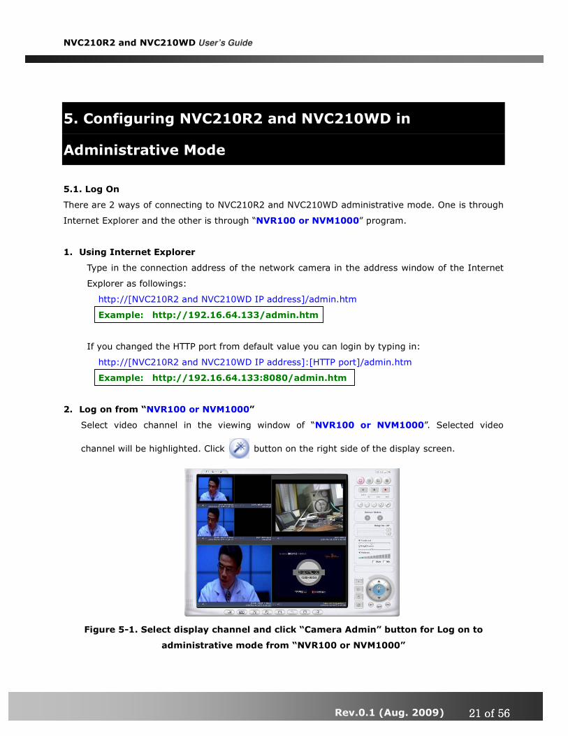
2. Log on from “NVR100 or NVM1000”
Select video channel in the viewing window of “NVR100 or NVM1000”. Selected video
channel will be highlighted. Click button on the right side of the display screen.
Figure 5-1. Select display channel and click “Camera Admin” button for Log on to
administrative mode from “NVR100 or NVM1000”

NVC210R2 and NVC210WD User’s Guide
Rev.0.1 (Aug. 2009) 22222222 of 56 of 56 of 56 of 56
3. Input User Name and Password in the display screen shown in Figure 5-2.
Figure 5-2. Log On Screen
Factory default User Name and Password are set as ‘root’ and ‘root’, respectively. Click on “OK”
button to enter into the Basic Setup page of Administrative Mode. If you have changed the username
and password of the Administrator, you must log on with the changed username and password.

NVC210R2 and NVC210WD User’s Guide
Rev.0.1 (Aug. 2009) 23232323 of 56 of 56 of 56 of 56
5.2. Basic Setup
Setup the basic parameters of the NVC210R2 and NVC210WD.
Figure 5-3. Basic Setup
Field/Button Sub Field
/Button Description
Language Select a language of your choice
System Name
Logical name of the NVC210R2 and NVC210WD. It is same as
the one set-up by IP-installer. You can reassign the system
name.
Audio Input
Selection
Select the type of input audio.
� Select Line In for using Line-out from audio devices.
� Select Mic for using microphone.
Video Quality Input Video This filed is set by the factory
NVC210R2 and NVC210WD User’s Guide
Rev.0.1 (Aug. 2009) 24242424 of 56 of 56 of 56 of 56
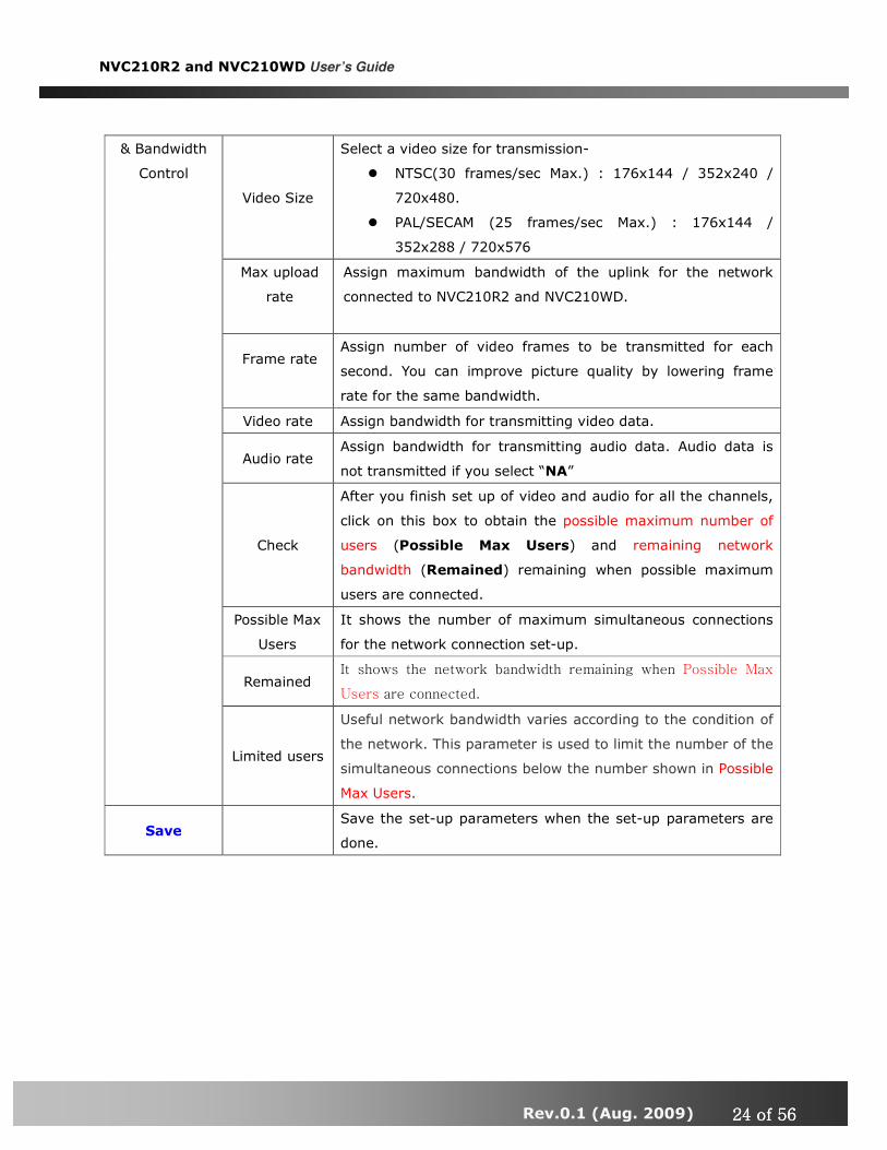
Video Size
Select a video size for transmission-
� NTSC(30 frames/sec Max.) : 176x144 / 352x240 /
720x480.
� PAL/SECAM (25 frames/sec Max.) : 176x144 /
352x288 / 720x576
Max upload
rate
Assign maximum bandwidth of the uplink for the network
connected to NVC210R2 and NVC210WD.
Frame rate
Assign number of video frames to be transmitted for each
second. You can improve picture quality by lowering frame
rate for the same bandwidth.
Video rate Assign bandwidth for transmitting video data.
Audio rate Assign bandwidth for transmitting audio data. Audio data is
not transmitted if you select “NA”
Check
After you finish set up of video and audio for all the channels,
click on this box to obtain the possible maximum number of
users (Possible Max Users) and remaining network
bandwidth (Remained) remaining when possible maximum
users are connected.
Possible Max
Users
It shows the number of maximum simultaneous connections
for the network connection set-up.
Remained It shows the network bandwidth remaining when Possible Max
Users are connected.
& Bandwidth
Control
Limited users
Useful network bandwidth varies according to the condition of
the network. This parameter is used to limit the number of the
simultaneous connections below the number shown in Possible
Max Users.
Save Save the set-up parameters when the set-up parameters are
done.

NVC210R2 and NVC210WD User’s Guide
Rev.0.1 (Aug. 2009) 25252525 of 56 of 56 of 56 of 56
5.3. Network Configuration
Setup the network parameters appropriately in accordance with your network environment. Many
of the parameters in this page are same as those set up by “IP-Installer”.
Figure 5-4. Network Configuration
Field/Button Sub Field
/Button Description
IP Assign Type
The network types supported by the NVC210R2 and

NVC210R2 and NVC210WD User’s Guide
Rev.0.1 (Aug. 2009) 26262626 of 56 of 56 of 56 of 56
NVC210WD are LAN(fixed IP), PPPoE, and DHCP(automatic IP
allocation)
Static IP
Setup
When the network environment is fixed IP, select ‘LAN’ in the
network type, and put the IP address, Subnet Mask, Gateway,
DNS1 and DNS2. Ask your network administrator or ISP for the
information. DNS2 is used when DNS1 does not work.
PPPoE Setup
When the network environment is PPPoE and IP address is
assigned automatically, select ‘PPPoE’ in the network type.
Next, fill in the ‘User Name’ and ‘Password’ fields with the
values assigned by the ISP.
DHCP Setup
When the network environment is “automatic IP allocation by
DHCP”, select ‘DHCP’ in the network type. For cable modem
connection, select this mode.
Refer to [IP-installer user’s guide] for “Host name and
domain for Cable Modem
Clone MAC Refer to [IP-installer user’s guide] for “Clone MAC”
Each port should have a number below 65535.
RTSP The RTSP port is used for transmitting real time audio/video
data from the network camera. Default is 554. Port Change
HTTP HTTP port is used for the connection to the admin page.
Default is 80.
You can restrict the access to the administrator page from IP
addresses beyond certain IP address range.
Restrict
Administrator
Access
Check at this box to restrict administrative log on.
Base IP
Address
Input IP address of the PC which is intended to be used for log
on to administrative mode.
IP Filtering
Mask
This is same as subnet mask. It is used to allow administrative
log on only to the PCs located in the same subnet as the base
IP address. If you want to allow only one PC to access in
administrative mode, set this value to 255.255.255.255.
E-Mail Setup
Notify for IP
Change
If you check this, the IP address will be sent via E-mail
whenever the IP address changes. It is sent to the E-mail
address set by “Recv E-Mail Address”.

NVC210R2 and NVC210WD User’s Guide
Rev.0.1 (Aug. 2009) 27272727 of 56 of 56 of 56 of 56
Recv E-Mail
Address
Enter E-mail address to receive information sent from your
network camera. This is same as E-mail field in IP-installer.
Return E-Mail
Address
Fill in this field with correct e-mail address to identify the mail
sent from the network camera
Using Built-in
SMTP Server
If you are using web mail services having no SMTP server,
check the radio button at the left of “Using Built-in SMTP
Server” and enter valid e-mail address to avoid spam filtering
on the receiving e-mail server.
Using
External
SMTP Server
If you are using external mail server, fill in the fields with
proper parameters.
FTP Server
Setup
Setup IP address, Username, Password and Directory of FTP
server to send data in case of alarm. Default FTP port number
is 21.
You can register the network camera to the Management
Server (DDNS Server) for name service to your network
camera.
Management
Server Log on to
server
Check this box to enable log on to the management server. By
log on to the management server your network camera can use
domain name instead of numeric IP address. This feature is
particularly useful when your network camera is using dynamic
IP address. Input valid management server (DDNS Server)
name for the service.
You must have an account on the management server (DDNS
Server) and register your IP video devices under your account
to use this feature.
Domain name of your network camera can be assigned when
you register your network camera to the management server
under your account.
One of the servers available is mgmt.net-video.net. For
opening an account, visit www.net-video.net .
NVC210R2 and NVC210WD User’s Guide
Rev.0.1 (Aug. 2009) 28282828 of 56 of 56 of 56 of 56
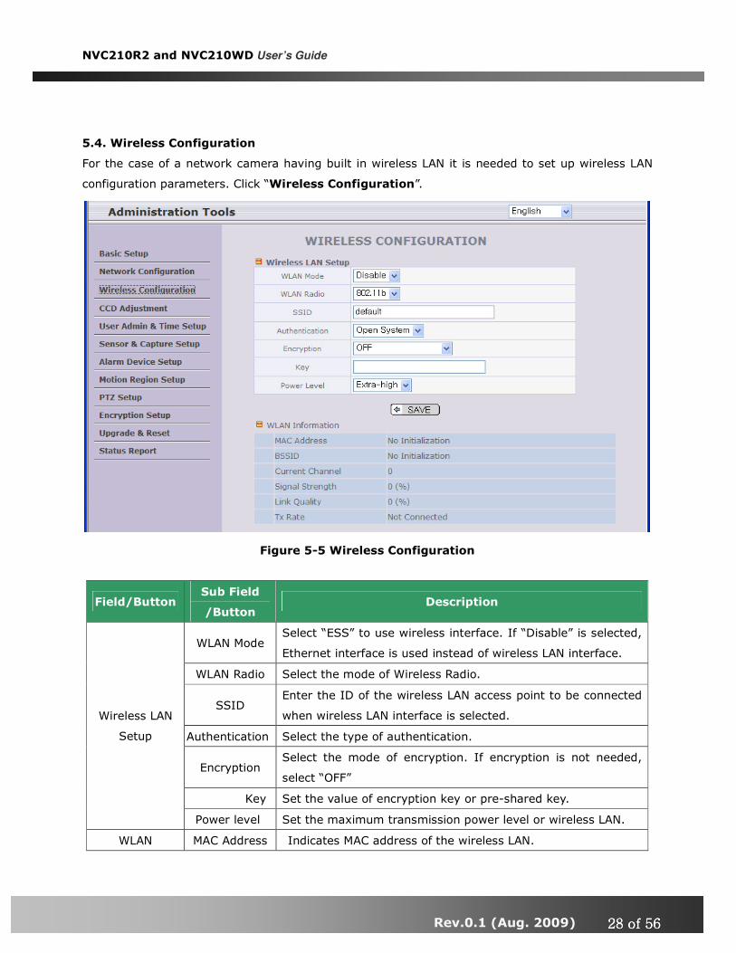
5.4. Wireless Configuration
For the case of a network camera having built in wireless LAN it is needed to set up wireless LAN
configuration parameters. Click “Wireless Configuration”.
Figure 5-5 Wireless Configuration
Field/Button Sub Field
/Button Description
WLAN Mode Select “ESS” to use wireless interface. If “Disable” is selected,
Ethernet interface is used instead of wireless LAN interface.
WLAN Radio Select the mode of Wireless Radio.
SSID Enter the ID of the wireless LAN access point to be connected
when wireless LAN interface is selected.
Authentication Select the type of authentication.
Encryption Select the mode of encryption. If encryption is not needed,
select “OFF”
Key Set the value of encryption key or pre-shared key.
Wireless LAN
Setup
Power level Set the maximum transmission power level or wireless LAN.
WLAN MAC Address Indicates MAC address of the wireless LAN.
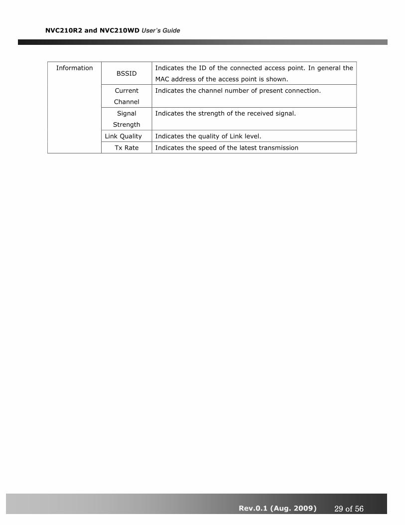
NVC210R2 and NVC210WD User’s Guide
Rev.0.1 (Aug. 2009) 29292929 of 56 of 56 of 56 of 56
BSSID Indicates the ID of the connected access point. In general the
MAC address of the access point is shown.
Current
Channel
Indicates the channel number of present connection.
Signal
Strength
Indicates the strength of the received signal.
Link Quality Indicates the quality of Link level.
Information
Tx Rate Indicates the speed of the latest transmission
NVC210R2 and NVC210WD User’s Guide
Rev.0.1 (Aug. 2009) 30303030 of 56 of 56 of 56 of 56
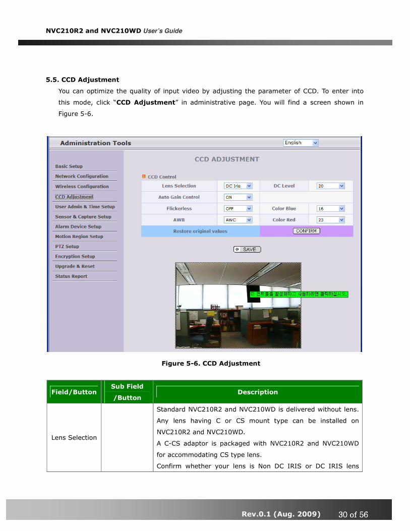
5.5. CCD Adjustment
You can optimize the quality of input video by adjusting the parameter of CCD. To enter into
this mode, click “CCD Adjustment” in administrative page. You will find a screen shown in
Figure 5-6.
Figure 5-6. CCD Adjustment
Field/Button Sub Field
/Button Description
Lens Selection
Standard NVC210R2 and NVC210WD is delivered without lens.
Any lens having C or CS mount type can be installed on
NVC210R2 and NVC210WD.
A C-CS adaptor is packaged with NVC210R2 and NVC210WD
for accommodating CS type lens.
Confirm whether your lens is Non DC IRIS or DC IRIS lens

NVC210R2 and NVC210WD User’s Guide
Rev.0.1 (Aug. 2009) 31313131 of 56 of 56 of 56 of 56
before your selection and then click “SAVE” to save your
selection.
DC IRIS Lens
DC IRIS lens is a kind of auto IRIS lens. Opening of IRIS can
be adjusted by applying DC voltage. The opening of IRIS is
optimally adjusted by detecting the signal level from CCD. This
type should be selected when DC IRIS lens is mounted on your
NVC210R2 and NVC210WD.
ELC Manual Lens without IRIS control
Backlight
Compensation
When the camera is acquiring video from object with bright
backlight, it is hard to identify the details of target object since
the object appears very dark. Apply backlight compensation
mode for this case. Default mode is backlight compensation
Off.
Auto Gain
Control
If you set the value to ON, the gain is automatically adjusted in
accordance with the illumination condition.
CCD Control
Flickerless
In case of using NTSC type NVC210R2 and NVC210WD in 50Hz
AC regions or using PAL type NVC210R2 and NVC210WD in
60Hz AC region, video output tends to flicker when NVC210R2
and NVC210WD is used under fluorescent lamps. This mode
reduces the flickering phenomena. If this mode is selected,
electronic shutter speed is set to 1/100 sec for NTSC camera
while it is set to 1/120 for PAL camera to synchronize the
shutter speed to AC current.
<Note> : Make sure that you apply this mode only when using
NTSC camera in PAL region or PAL camera in NTSC region.
AWB
AWC : Apply this mode for normal usage. This mode provides
even color reproduction for wide range of color temperature.
ATW : This mode provides coverage for narrower color
temperature.
Sharpness Adjust the sharpness of the video
DC level Adjust the brightness level by adjust this value.
Color Blue Adjust the amount of blue in the video.
Color Red Adjust the amount of red in the video
Restore
Original Values
Apply original setting of the values.
SAVE Click “SAVE” to save your selection.
NVC210R2 and NVC210WD User’s Guide
Rev.0.1 (Aug. 2009) 32323232 of 56 of 56 of 56 of 56
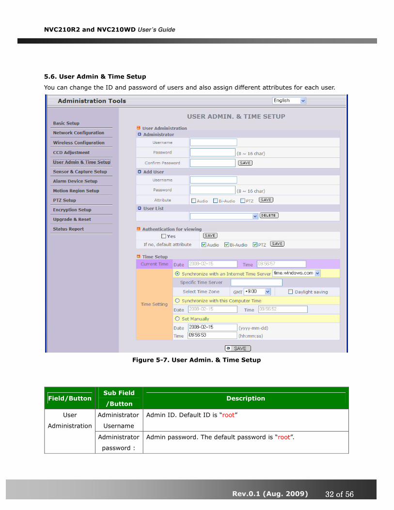
5.6. User Admin & Time Setup
You can change the ID and password of users and also assign different attributes for each user.
Figure 5-7. User Admin. & Time Setup
Field/Button Sub Field
/Button Description
Administrator
Username
Admin ID. Default ID is “root” User
Administration
Administrator
password :
Admin password. The default password is “root”.
NVC210R2 and NVC210WD User’s Guide
Rev.0.1 (Aug. 2009) 33333333 of 56 of 56 of 56 of 56
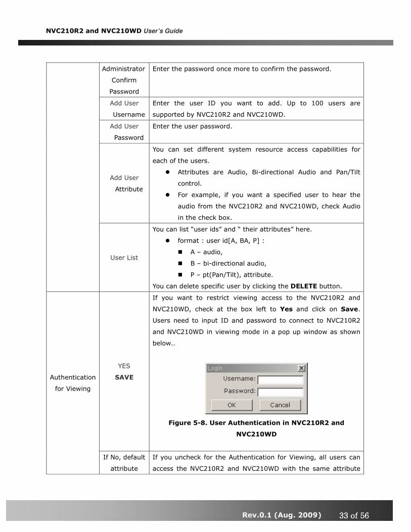
Administrator
Confirm
Password
Enter the password once more to confirm the password.
Add User
Username
Enter the user ID you want to add. Up to 100 users are
supported by NVC210R2 and NVC210WD.
Add User
Password
Enter the user password.
Add User
Attribute
You can set different system resource access capabilities for
each of the users.
� Attributes are Audio, Bi-directional Audio and Pan/Tilt
control.
� For example, if you want a specified user to hear the
audio from the NVC210R2 and NVC210WD, check Audio
in the check box.
User List
You can list “user ids” and “ their attributes” here.
� format : user id[A, BA, P] :
� A – audio,
� B – bi-directional audio,
� P – pt(Pan/Tilt), attribute.
You can delete specific user by clicking the DELETE button.
YES
SAVE
If you want to restrict viewing access to the NVC210R2 and
NVC210WD, check at the box left to Yes and click on Save.
Users need to input ID and password to connect to NVC210R2
and NVC210WD in viewing mode in a pop up window as shown
below..
Figure 5-8. User Authentication in NVC210R2 and
NVC210WD
Authentication
for Viewing
If No, default
attribute
If you uncheck for the Authentication for Viewing, all users can
access the NVC210R2 and NVC210WD with the same attribute

NVC210R2 and NVC210WD User’s Guide
Rev.0.1 (Aug. 2009) 34343434 of 56 of 56 of 56 of 56
set here. Checked attributes are enabled. Click “Save” to save
the attribute.
Current Time It shows you the current time of NVC210R2 and NVC210WD.
Synchronize
with an
Internet
Time Server
Synchronize the time with the internet time server at the right.
When the time server is out of the reach from NVC210R2 and
NVC210WD, you can assign time server by filling in Specific
Time Server field.
Synchronize
With this
Computer
Time
Synchronize the time with the time of the PC. Time Setup
Set Manually Set the time manually. Fill in the fields with desired formats.
SAVE Save the set up parameters
If you lost Administrator’s ID and password, the only means of recovery is to reset
the settings to factory default, but then you lose your previous settings.

NVC210R2 and NVC210WD User’s Guide
Rev.0.1 (Aug. 2009) 35353535 of 56 of 56 of 56 of 56
5.7. Sensor & Capture Setup
This is the setup page for sensors and video capture conditions. Captured video can be sent to user
by FTP or E-mail upon configuration.
Figure 5-9. Sensor & Capture Setup
Field/Button Sub Field
/Button Description
Sensor 1 Select sensor type. There are two types of sensors which are
Normal Open and Normal Close. Sensor Setup
Name Input logical name for the sensor.
Video Capture
Condition
It sets the condition of video transmission via FTP or E-mail.
The NVC210R2 and NVC210WD supports 2 types of conditions
which are mutually independent.
1. Sensor initiated: when at least one of the sensor
detects alarm condition.
2. Motion-Detection initiated : when motion is
detected from video channel

NVC210R2 and NVC210WD User’s Guide
Rev.0.1 (Aug. 2009) 36363636 of 56 of 56 of 56 of 56
Sensor
Select
Check to enable Sensor initiated capture.
Motion
Detection
Select
Check to enable motion detection initiated capture.
Select a way of sending captured video. You can send captured
video through FTP or E-mail, or both.
-
By E-Mail
Check to send captured video by e-mail.
E-mail is sent to the Recv E-mail address. Refer to [Section
5.3.]
Captured video data for E-mail consists of intra frames only in
consideration of the limited storage space for E-mail account.
FTP data contains entire video frames.
Captured
Video
Transmission
By FTP
Check to send captured video by FTP.
FTP is sent to the FTP Server. Refer to [Section 5.3.]
If the FTP server is not properly assigned in “Network
Configuration” mode, NVC210R2 and NVC210WD ignores the
video transmission by FTP
SAVE Save the setup parameters.
NVC210R2 and NVC210WD User’s Guide
Rev.0.1 (Aug. 2009) 37373737 of 56 of 56 of 56 of 56
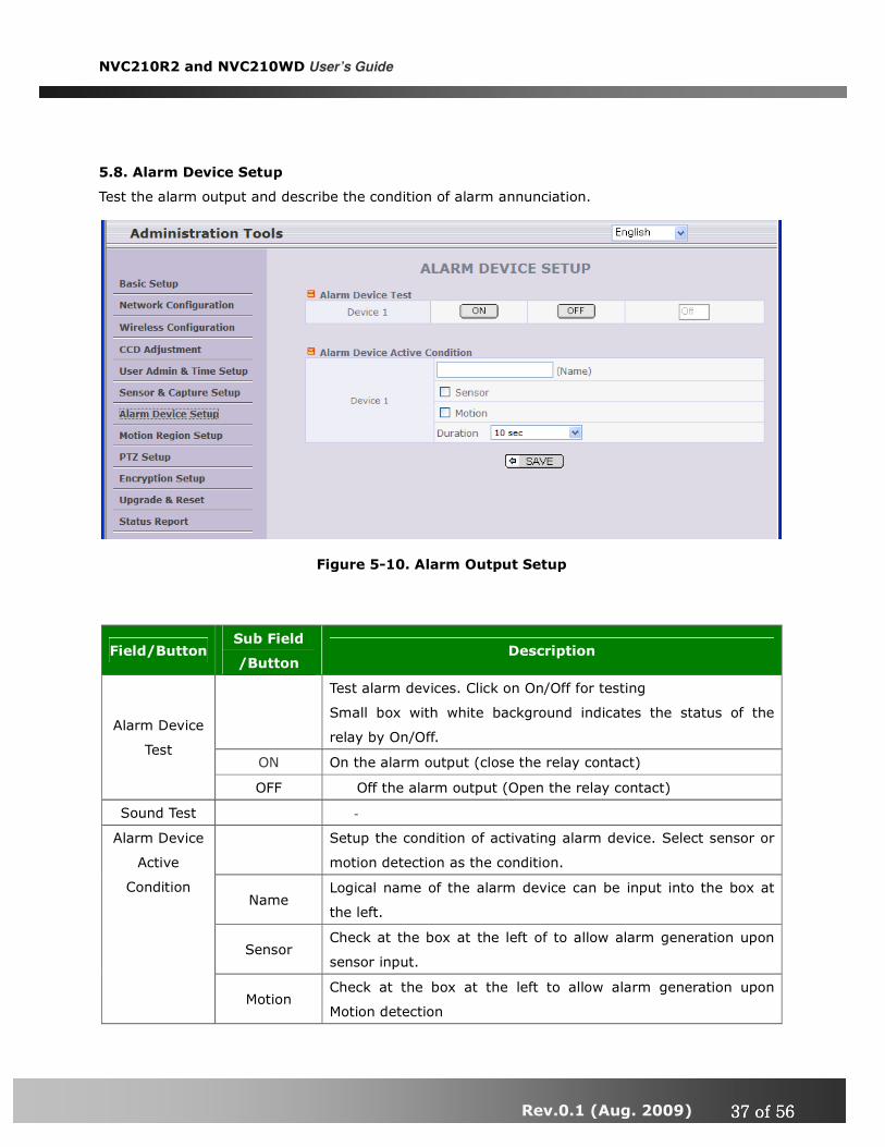
5.8. Alarm Device Setup
Test the alarm output and describe the condition of alarm annunciation.
Figure 5-10. Alarm Output Setup
Field/Button Sub Field
/Button Description
Test alarm devices. Click on On/Off for testing
Small box with white background indicates the status of the
relay by On/Off.
ON On the alarm output (close the relay contact)
Alarm Device
Test
OFF Off the alarm output (Open the relay contact)
Sound Test -
Setup the condition of activating alarm device. Select sensor or
motion detection as the condition.
Name Logical name of the alarm device can be input into the box at
the left.
Sensor Check at the box at the left of to allow alarm generation upon
sensor input.
Alarm Device
Active
Condition
Motion Check at the box at the left to allow alarm generation upon
Motion detection

NVC210R2 and NVC210WD User’s Guide
Rev.0.1 (Aug. 2009) 38383838 of 56 of 56 of 56 of 56
Duration Set the duration of Alarm annunciation.
10 sec, 30 sec, 1 min, 2 min, 5 min, 10 min, 30 min, 1 hour.
SAVE Save the setup parameters.

NVC210R2 and NVC210WD User’s Guide
Rev.0.1 (Aug. 2009) 39393939 of 56 of 56 of 56 of 56
5.9. Motion Region Setup
Set the motion detection regions. Up to 3 regions can be defined.
Field/Button Sub Field
/Button Description
Channel
Selection
Not applicable.
Channel
Sensitivity
Set the sensitivity in motion detection for each channel. 1 is the
most sensitive, and 10 is the least sensitive.
Set up to 3 the motion detection zone Motion Region
Setup
Region 1, 2,
or 3
Enable each zone by checking the box at the left of each Region.
. To set the region,
Figure 5-11. Motion Region Setup

NVC210R2 and NVC210WD User’s Guide
Rev.0.1 (Aug. 2009) 40404040 of 56 of 56 of 56 of 56
1. Click on START and click on a box overlaid on the
video
2. Click on END and click on a box overlaid on the video.
3. The defined motion detection zone will be indicated
with corresponding colors.
Legend of the color :
red(region 1),
green(region 2),
blue(region3).
START Enable selection of rectangular zone start.
END Enable selection of rectangular zone end.
SELECT Click on this button and click on desired rectangle to add or delete
the rectangular region to the motion detection zone.
Percentage This value controls the sensitivity of each region.
1 is the most sensitive and 100 is the least sensitive
RESET Clears the start & end point to (0,0) & (0,0)
SAVE Save the setup parameters.
NVC210R2 and NVC210WD User’s Guide
Rev.0.1 (Aug. 2009) 41414141 of 56 of 56 of 56 of 56
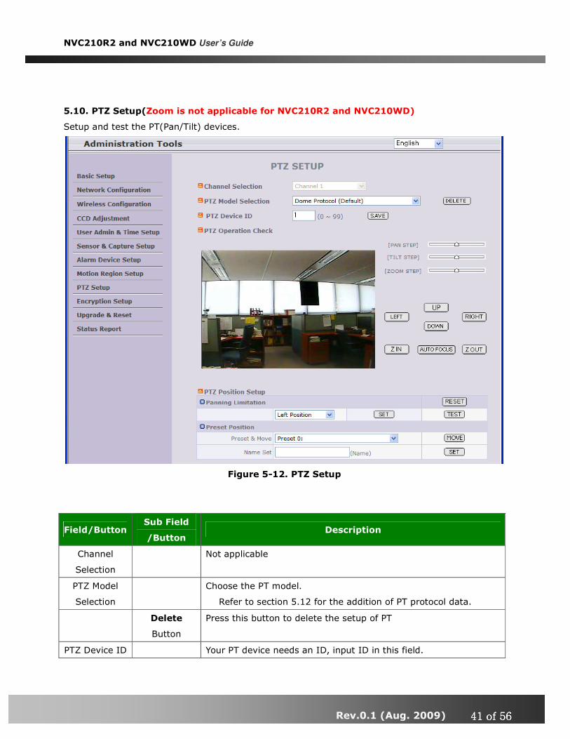
5.10. PTZ Setup(Zoom is not applicable for NVC210R2 and NVC210WD)
Setup and test the PT(Pan/Tilt) devices.
Figure 5-12. PTZ Setup
Field/Button Sub Field
/Button Description
Channel
Selection
Not applicable
PTZ Model
Selection
Choose the PT model.
Refer to section 5.12 for the addition of PT protocol data.
Delete
Button
Press this button to delete the setup of PT
PTZ Device ID Your PT device needs an ID, input ID in this field.

NVC210R2 and NVC210WD User’s Guide
Rev.0.1 (Aug. 2009) 42424242 of 56 of 56 of 56 of 56
Click on SAVE to save the ID.
Note that zoom is not applicable for NVC210R2 and
NVC210WD.
PTZ Operation
Check
You can check the various operation of the PT devices.
“Left”/”Right”/”UP”/”DOWN”
You can set up the PTZ limitation & preset positions if the PT
device supports it.
Panning
Limitation
Set the left/right limitation and test.
Select Left/Right position before setting.
Panning
Limitation
RESET
Clear the panning limitation previously set.
The panning range will be the same as the PT device allows.
Panning
Limitation
SET
Set the present position as left or right panning limitation.
Panning
Limitation
TEST
Test the panning limitation which was set previously.
Preset
Position :
Set the preset position and test.
Preset
Position
Preset &
Move
Select a preset position to move to. Movement to the preset
position will be made upon clicking on “MOVE”
Preset
Position
Name Set
Assign logical name for the preset position. Enter into the field
and click on SET.
PTZ Position
Setup
Preset
Position
Set
Set the present position as a preset position with position number
shown at the right of “Preset & Move” and name shown at the
right of “Name Set”.
<Note> : “PTZ Position Setup” feature is applicable only for the PT devices that support it.

NVC210R2 and NVC210WD User’s Guide
Rev.0.1 (Aug. 2009) 43434343 of 56 of 56 of 56 of 56
5.11. Encryption Set up
Figure 5-13. Encryption Setup
For additional security to the video and audio data transmitted from the network camera, you can
set key codes and use them for encrypting the data from the network camera.
You can selectively activate encryption for the video and audio data. For enabling the encryption,
check at the box at the left of the “Enable data encryption” then check at the proper check boxes at
the left of “Video” and “Audio”. After the selection, click on SAVE button beneath the “Video” and
“Audio” check boxes.
Field/Button Sub Field
/Button Description
Check at this box to apply data encryption.
If it is unchecked encryption is applied on neither video nor
audio data regardless of the selection below.
Video Check to enable encryption on the video data.
Enable Data
Encryption
Audio Check to enable encryption on the audio data.

NVC210R2 and NVC210WD User’s Guide
Rev.0.1 (Aug. 2009) 44444444 of 56 of 56 of 56 of 56
SAVE After the selection, click on SAVE button.
You can use up to 20 different key codes for the encryption of
the data
GENERATE To generate the key value click on “GENERATE” button. The
boxes for the Key values will be filled with new values.
SAVE
Save Key value on the network camera: Click on SAVE
button beneath GENERATE button to save the key value
generated by the network camera.
DOWNLOAD
Download Key value to your PC : The key values can be
downloaded and stored as a file to your PC for reference when
you make connection. When encryption is enabled, the PC
client program will ask for particular key value out of the 20
available key values.
Key Value
INSTALL
Upload key value to the network camera : The key value
stored on your PC can be uploaded to your network camera.
This feature is useful when you manage multiple network
cameras having same key value sets. Select a file having key
values then click on “INSTALL” button to upload the key values.
Find file saving the Key value before uploading to the network
camera.

NVC210R2 and NVC210WD User’s Guide
Rev.0.1 (Aug. 2009) 45454545 of 56 of 56 of 56 of 56
5.12. Upgrade & Reset
You can upgrade the NVC210R2 and NVC210WD via the IP network.
Figure 5-14. Upgrade & Reset
For each of the upgrade of the system component, upgrade code should be downloaded from
Inscape Data’s home page before the system upgrade is performed.
(Refer to [6.4. How to Upgrade Your NVC210R2 and NVC210WD System]
Field/Button Sub Field
/Button Description
Automatic
Upgrade
Automatic upgrade is a feature that enables network camera to
upgrade to newly released system software by automatically
connecting to upgrade server. Click on check button to find the
availability of upgrade firmware.
Note that automatic upgrade is not supported for
standard product.
Upgrade the system manually. Manual
Upgrade
System S/W
Upgrade
Upgrade the system software installed in the network camera
via the network. System software needed for the upgrade can

NVC210R2 and NVC210WD User’s Guide
Rev.0.1 (Aug. 2009) 46464646 of 56 of 56 of 56 of 56
be downloaded from Inscape Data’s home page.
Refer to [6.4. How To Upgrade Your NVC210R2 and
NVC210WD System].
Bootloader
Upgrade
Upgrade the bootloader installed in the network camera via the
network. Bootloader needed for the upgrade can be
downloaded from Inscape Data’s home page.
Refer to [6.4. How To Upgrade Your NVC210R2 and
NVC210WD System].
Add PTZ File
Add a new PT driver software via the network. PT driver can be
downloaded from Inscape Data’s home page.
Refer to [6.4. How To Upgrade Your NVC210R2 and
NVC210WD System].
Factory
Default
Setting
Re-initialize the network camera to factory default state.
By checking on a Radio button “Except Network Configuration”,
you can preserve the parameters for the network. Checking on
“All”, will return all the parameters to factory default state.
Once NVC210R2 and NVC210WD is re-initialized as
factory default state, it should be set-up again using IP-
Installer.
System Reset
Perform remote reset by clicking the “CONFIRM” button.
All previous connections will be disconnected upon
reset. NVC210R2 and NVC210WD does not resume the
connections and the users must re-connect to the server
manually.

NVC210R2 and NVC210WD User’s Guide
Rev.0.1 (Aug. 2009) 47474747 of 56 of 56 of 56 of 56
5.13. Status Report
It shows you system records since the system started.
You can check the problems as well as the versions and event status of the whole system and each
module.
Figure 5-15. Status Report

NVC210R2 and NVC210WD User’s Guide
Rev.0.1 (Aug. 2009) 48484848 of 56 of 56 of 56 of 56
6. Tips for using NVC210R2 and NVC210WD
6.1. ALARM-IN and ALARM-OUT
ALARM connectors are used to connect various sensing and alerting devices. Examples of sensing
devices are infrared sensors, motion sensors, heat/smoke sensors, magnetic sensor, etc. ALARM-
OUT is used for connecting alerting device such as loud speaker, flashing light, etc.
Figure 6-1. Terminal block for I/O connection
1. ALARM-IN
Connect the two wires of the sensors to “SNS IN”. The sensor type can be set in
Administrative mode(Ref. 5.7). Output lines providing on-off switching are connected
between “+“ and “-” pins.
Figure 6-2 shows the input circuit of “SNS IN”.

NVC210R2 and NVC210WD User’s Guide
Rev.0.1 (Aug. 2009) 49494949 of 56 of 56 of 56 of 56
2. ALARM-OUT
A Relay output is provided for connecting alarm devices or for remote on/off devices
such as light control. Relay circuits are normal open and circuits are closed upon alarm
output or remote on. The relay is capable of switching AC/DC 30V,1A electrical signal.
RLY OUT
RLY OUT
Figure 6-3. RELAY Output of NVC210R2 and NVC210WD
SNS IN (+)
SNS IN (-)
Figure 6-2. SENSOR input of NVC210R2 and NVC210WD

NVC210R2 and NVC210WD User’s Guide
Rev.0.1 (Aug. 2009) 50505050 of 56 of 56 of 56 of 56
3. Connection of Sensor, Alarm Device
3.1 Connection of Sensor
S ensorS ensorS ensorS ensorD eviceD eviceD eviceD evice
S ensorS ensorS ensorS ensorP ow erP ow erP ow erP ow erS upplyS upplyS upplyS upply
N O /N C TypeN O /N C TypeN O /N C TypeN O /N C Type
S ensor1-S ensor1-S ensor1-S ensor1-
S enso r1+S enso r1+S enso r1+S enso r1+
+12V+12V+12V+12VG N DG N DG N DG N D
Sensor Sensor Sensor Sensor D evice D evice D evice D evice
S enso rS enso rS enso rS enso rP ow erP ow erP ow erP ow erS upplyS upplyS upplyS upply
O pen C ollectorTypeO pen C ollectorTypeO pen C ollectorTypeO pen C ollectorTypePhoto C oupler
3.2 Connection of Relay
A larmA larmA larmA larmO utO utO utO ut
D eviceD eviceD eviceD evice
R elay1
P ow erP ow erP ow erP ow erS upplyS upplyS upplyS upply((((1111~30
VDC/AC,1A ))))
R elay1++++
----
Relay Sw itch Pow er Supply1V~ 30VD C /A C ,1A1V~ 30VD C /A C ,1A1V~ 30VD C /A C ,1A1V~ 30VD C /A C ,1A
O ptionalR elay Sw itch
A larmA larmA larmA larmO utO utO utO ut
D eviceD eviceD eviceD evice
P ow erP ow erP ow erP ow erS upply(S upply(S upply(S upply(30V
~)
R elay
You can use the supported relay output to directly drive a maximum load of
30V AC/DC at 1A. By connecting additionally relay circuitry (such as optional relay
switch), it can also drive heavier loads.

NVC210R2 and NVC210WD User’s Guide
Rev.0.1 (Aug. 2009) 51515151 of 56 of 56 of 56 of 56
6.2. Trouble Shooting
1. After NVC210R2 and NVC210WD is successfully installed.
• NVC210R2 and NVC210WD in viewing mode, neither channel name nor video is display
and eventually timeout message is shown up.
Check the power and network connection of NVC210R2 and NVC210WD.
To check if the network is properly operating, open the browser and try to connect to any
server.
Example) http://www.yahoo.com
Or open the MS-DOS Prompt and type the following.
ping www.yahoo.com
Then press Enter. If you see the “ Reply from …” message it means that the network is
working properly. To check if the NVC210R2 and NVC210WD is connected, open the MS-
DOS Prompt and type the following.
ping [the IP of the server]
Example) ping 192.168.1.112
If you see the “Reply from …” message, it means that the server is properly connected.
If you do not see a Reply message, check if the network cable and power cable are
properly connected.
2. After Successfully Connecting to the NVC210R2 and NVC210WD
• Video movement is slow.
In Basic Setup of Admin Mode, lower the “Quality”. High quality means more data. You can also
set the “Max. upload rate” to higher value. But this value must be lower than the maximum
upload speed of your network. For example, if the maximum uploading bandwidth of the
network is 400Kbps, set the total “Max. upload rate” as 384Kbps. If you set it higher, the video
image can be corrupted with artifacts.
Ask your network manager or ISP for maximum uploading bandwidth of the network.
• The image is dull and I see green, pink dots.
This could be caused by performance limitation of the PC. Do not run too many programs while

NVC210R2 and NVC210WD User’s Guide
Rev.0.1 (Aug. 2009) 52525252 of 56 of 56 of 56 of 56
running viewer program. The other reason could be missing data while transmission from
NVC210R2 and NVC210WD.
•••• Mosaic phenomenon.
Mosaic phenomenon occurs when not enough network bandwidth is available considering the
resolution and frame rate of the video.
Example is 704x480 video with low Max. upload rate.
Users are recommended to adjust resolution and frame rates to lower values for lower
bandwidth network.
6.3. Web Viewer
NVC210R2 and NVC210WD is designed to be connected through internet explorer, too. For
connection to NVC210R2 and NVC210WD using internet explorer type in IP address or host address
in the address input field of the internet explorer.
Figure 6-4. Web Viewer of NVC210R2 and NVC210WD
� Control Panel of Web Viewer

NVC210R2 and NVC210WD User’s Guide
Rev.0.1 (Aug. 2009) 53535353 of 56 of 56 of 56 of 56
Enable bidirectional audio. When
bidirectional audio is enabled, voice
from your PC is delivered to NVC210R2
and NVC210WD.
Capture and store the still image on
your desk top screen.
Connect to NVC210R2 and NVC210WD
in administrative mode of NVC210R2
and NVC210WD.
Rotate the screen by 180 degree.
Connect to NVC210R2 and NVC210WD.
Stop the connection.
Contrast, Brightness, and Volume
adjustment..
Check the box to mute the audio.
Adjust the size of the screen. Normal
(x1), Twice (x2), Half (1/2), Full Screen
(full)
On/off the relay by pressing the button
Shows the status of the sensor. Blue
color means that the sensor is in normal
state, while red color indicates alarm
situation.
Number on the button indicates the
number of sensor.
Move the center of the camera in
up/down/left/right directions.
NVC210R2 and NVC210WD User’s Guide
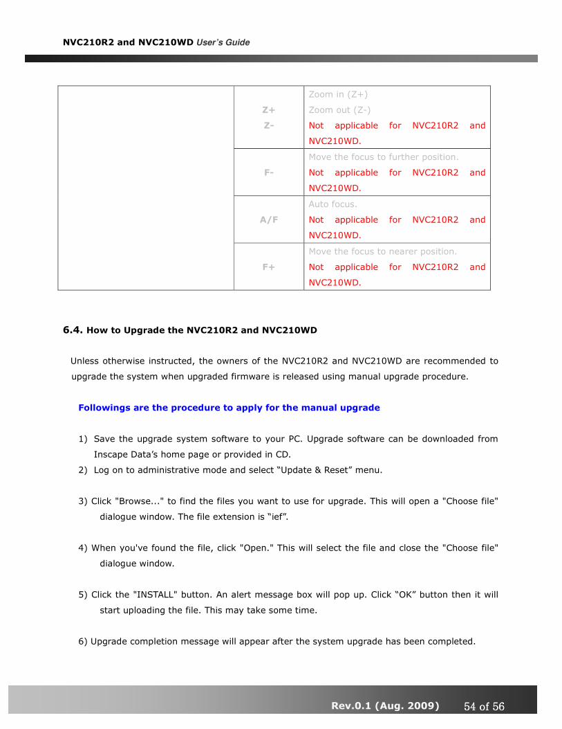
Rev.0.1 (Aug. 2009) 54545454 of 56 of 56 of 56 of 56
Z+
Z-
Zoom in (Z+)
Zoom out (Z-)
Not applicable for NVC210R2 and
NVC210WD.
F-
Move the focus to further position.
Not applicable for NVC210R2 and
NVC210WD.
A/F
Auto focus.
Not applicable for NVC210R2 and
NVC210WD.
F+
Move the focus to nearer position.
Not applicable for NVC210R2 and
NVC210WD.
6.4. How to Upgrade the NVC210R2 and NVC210WD
Unless otherwise instructed, the owners of the NVC210R2 and NVC210WD are recommended to
upgrade the system when upgraded firmware is released using manual upgrade procedure.
Followings are the procedure to apply for the manual upgrade
1) Save the upgrade system software to your PC. Upgrade software can be downloaded from
Inscape Data’s home page or provided in CD.
2) Log on to administrative mode and select “Update & Reset” menu.
3) Click "Browse..." to find the files you want to use for upgrade. This will open a "Choose file"
dialogue window. The file extension is “ief”.
4) When you've found the file, click "Open." This will select the file and close the "Choose file"
dialogue window.
5) Click the "INSTALL" button. An alert message box will pop up. Click “OK” button then it will
start uploading the file. This may take some time.
6) Upgrade completion message will appear after the system upgrade has been completed.

NVC210R2 and NVC210WD User’s Guide
Rev.0.1 (Aug. 2009) 55555555 of 56 of 56 of 56 of 56
7) Reboot NVC210R2 and NVC210WD by performing “System Reset”.
8) After rebooting, log on to the server in administrative mode again and click the “Status
Report”.
9) Check the version number and release date of the NVC210R2 and NVC210WD.
You can download NVC210R2 and NVC210WD system software from
inscapedata’s homepage. http://www.inscapedata.com