airpoxy...airpoxy thermoformable, repairable and bondable smart epoxy- based composites for aero...
TRANSCRIPT
AIRPOXY Thermoformable, repairable and bondable smart
epoxy- based composites for aero structures
Deliverable 1.2
Report on the preliminary analysis and definition of process
technologies requirements for manufacturing, 3R bonding and repair
Grant Agreement Number: 769274
Start Date of the Project: 1 September 2018
Duration: 42 months
Deliverable lead beneficiary: EIRE
Due date of deliverable: 28/02/2019
Actual submission date: 28/02/2019
Dissemination level: Public

D 1.2. – Report on the preliminary analysis and definition of process technologies requirements for manufacturing, 3R bonding and repair
Public 2
Revision history
R# Date Description / Reason of change Author
D1 21/01/2019 Draft for Consortium Bryan Weafer
D2 28/01/2019 Draft for Consortium Michael Flanagan
D3 14/02/2019 Draft for Consortium Michael Flanagan
R1.0 27/02/2019 Final version for submission Michael Flanagan + Project Office
Authors
Beneficiary Name
EIRE Bryan Weafer, Tomas Flanagan, Michael Flanagan
IDEC Diego Calderón
SON Antoine De Fontgalland
IVW Stefan Weidmann, Christian Goergen, Andreas Krämer
CID Nerea Markaide
UOI Maria Kosarli, Georgios Foteinidis, Kyriaki Tsirka, Alkiviadis Paipetis
Content
Revision history ............................................................................................................................................................... 2
Authors ............................................................................................................................................................................ 2
List of Figures .................................................................................................................................................................. 3
Glossary ........................................................................................................................................................................... 5
1. Executive Summary ................................................................................................................................................. 6
2. Introduction ............................................................................................................................................................ 6
3. Equipment and Process Specification ..................................................................................................................... 8
3.1. Institut für Verbundwerkstoffe (IVW) ............................................................................................................. 8
3.1.1. Discontinuous Compression Molding (DCM) .......................................................................................... 8
3.1.2. Continuous Compression Molding (CCM) ............................................................................................. 10
3.1.3. Induction welding .................................................................................................................................. 13
3.2. EIRECOMPOSTIES (EIRE) ................................................................................................................................ 20

D 1.2. – Report on the preliminary analysis and definition of process technologies requirements for manufacturing, 3R bonding and repair
Public 3
3.2.1. Induction Welding ................................................................................................................................. 20
3.2.2. Thermoforming ..................................................................................................................................... 22
3.3. University of Ioannina (UOI) ......................................................................................................................... 22
3.3.1. Acoustic Emission (AE) .......................................................................................................................... 23
3.3.2. IR-Thermography (IR-T) ......................................................................................................................... 23
3.3.3. Ultrasonics ............................................................................................................................................. 24
3.3.4. Electrical Resistance Change Method ................................................................................................... 24
3.3.5. Impedance Spectroscopy (IS) ................................................................................................................ 25
3.4. INGENIERIA Y DESARROLLOS EN COMPOSITE (IDEC) .................................................................................... 26
3.4.1. RTM process. ......................................................................................................................................... 26
3.4.2. Material. ................................................................................................................................................ 27
3.4.3. Moulds .................................................................................................................................................. 28
3.4.4. Injection Equipment .............................................................................................................................. 28
Adhesion Process .......................................................................................................................................... 28
3.4.5. ..................................................................................................................................................................... 28
3.5. SOCIETE NATIONALE DE CONSTRUCTION AEROSPATIALE SONACA (SON) ................................................... 29
3.5.1. Demonstrator details ............................................................................................................................ 30
3.5.2. Thermoforming of webs........................................................................................................................ 31
3.5.3. SQRTM injection of skin ........................................................................................................................ 33
3.5.4. Welding of Webs to skin ....................................................................................................................... 35
4. Conclusion ............................................................................................................................................................. 35
5. Annex .................................................................................................................................................................... 35
6. References............................................................................................................................................................. 35
List of Figures
Figure 1:Technical demonstrators required for the project. .......................................................................................... 7
Figure 2: Infrared heating field ....................................................................................................................................... 9
Figure 3: Discontinuous Compression Molding (DCM) machine for Thermoforming process ....................................... 9

D 1.2. – Report on the preliminary analysis and definition of process technologies requirements for manufacturing, 3R bonding and repair
Public 4
Figure 4: Schematic sketch of continuous compression molding process ................................................................... 10
Figure 5: Drawing of the continuous compression molding press and of a qualitative process diagram .................... 11
Figure 6 Configuration of the CCM press at IVW .......................................................................................................... 12
Figure 7: Modular heating and cooling system temperature profile............................................................................ 12
Figure 8: Schematic of the experimental set-up of induction heating test rig (Becker & Mitschang, 2017) ............... 14
Figure 9: Discontinuous induction welding test rig ...................................................................................................... 15
Figure 10: Exemplary process flow of discontinuous induction welding ...................................................................... 15
Figure 11: Schematic representation of the assembly of the continuous induction welding process ......................... 17
Figure 12: Continuous induction welding test rig (2 Dimensional) ............................................................................... 18
Figure 13: Continuous induction welding robot ........................................................................................................... 19
Figure 14: ÉireComposites Induction Welder ............................................................................................................... 21
Figure 15: Heated hydraulic press used for thermoforming and press consolidation ................................................. 22
Figure 16. Implementation of acoustic emission on Mode-I test. ................................................................................ 23
Figure 17. Online IR-T measurement of TDCB specimen under mechanical loading. .................................................. 24
Figure 18. Ultrasonic experimental setup for monitoring the heating-cooling cycles of the 3R resin. ........................ 24
Figure 19. Experimental device for mechanical testing with simultaneous measurement of electrical resistance. ... 25
Figure 20. Impedance spectroscopy setup for heating-cooling cycle measurements. ................................................. 26
Figure 21. Impedance spectroscopy setup for SHM measurements. ........................................................................... 26
Figure 22: Fan Cowl demonstrator component ............................................................................................................ 27
Figure 23: Five Harness Satin Weave. ........................................................................................................................... 27
Figure 24: Airbus A350 showing close up of leading-edge structure. .......................................................................... 29
Figure 25: Detail of leading-edge demonstrator. .......................................................................................................... 30
Figure 26: Components and processes involved in manufacturing the final demonstrator. ....................................... 31
Figure 27: Left - image of final web. Centre - Drawing defining layup direction. Right - section view of fusion bond to
skin showing geometry of join including noodle filler. ................................................................................................. 32
Figure 28: Methods of producing the thermoformed half web ................................................................................... 33
Figure 29: Baseline lay-up of skin .................................................................................................................................. 34
Figure 30: Alternative layup sequence for skin ............................................................................................................. 34
Figure 31: Overview of the SQRTM process showing pro's and con's .......................................................................... 35

D 1.2. – Report on the preliminary analysis and definition of process technologies requirements for manufacturing, 3R bonding and repair
Public 5
Glossary
Abbreviation / acronym Description
AMGA Horizon 2020 Annotated Model Grant Agreement
CA Consortium Agreement
DOA Description of Action
EIRE European Commission
GA Grant Agreement
WP Work Package
RTM Resin Transfer Molding
SQRTM Same Qualified Resin Transfer Molding
SHM Structural Health Monitoring
CFRP Carbon Fibre Reinforced Polymer
GFRP Glass Fibre Reinforced Polymer
DCM Discontinuous Compression Moulding
IS Impedance Spectroscopy CCM Continuous Compression Moulding
Enduring prepreg The term “enduring” prepreg means that the prepreg ply is partially or completely cured, so it does not need to be stored refrigerated. The 3R material is in this case proposed as a roll or sheets of (almost) cured individual plies. Thanks to the welding properties of the 3R materials, there is no time limitation between the manufacturing date of the prepreg and its processing date

D 1.2. – Report on the preliminary analysis and definition of process technologies requirements for manufacturing, 3R bonding and repair
Public 6
1. Executive Summary
This document presents the specification for equipment and processes available from each of the project partners.
Details of the final demonstrators and the specific equipment that will be used in their manufacture are presented.
The purpose of the document is to ensure that the equipment and processes presented are suitable for meeting the
project goals. IVW have given details of their CCM, DCM and induction welding equipment that will be used for
process development. EIRE have resented the process capabilities of their induction welding and hydraulic press
which will be used for the demonstrator manufacture. UOI have presented the structural health monitoring
technology that they will be incorporating into the technology demonstrators. IDEC have given an overview of the
RTM and injection process that they will use in the project. SON have given details of the geometry and proposed
manufacturing methods for the final demonstrators.
2. Introduction
This report is intended to specify the equipment and processes to be used in the manufacture, assembly and repair
of composite components in industrial environment (WP5) using the 3R resin. The processes to be utilized during the
project will be developed to use the existing equipment and facilities available to the project partners. This will result
in reducing the Capital expenditure required in the manufacture of the demonstrators and in the envisaged serial
production process.
The aim of AIRPOXY is to reduce the production and maintenance costs of composite parts by introducing a novel
family of thermoset composites that preserve all the advantages of conventional thermosets, but can also be easily
processed and repaired, and even recycled. This will be achieved by the further development and validation of a
family of thermoset resins which present reversible or “dynamic” chemical bonds, recently developed by CIDETEC
(patent pending). These dynamic chemical bonds enable a series of “smart” properties, creating a new generation of
thermoset composites that preserve their high performance, in terms of easy fiber impregnation and overall stability,
while showing new unprecedented features once the composite is completely cured, such as Re-processability,
Reparability and Recyclability (3R).
Two demonstrators, shown in Figure 1, are to be manufactured using 3R resin and a number of cutting-edge
technologies in order to demonstrate the advantages made possible by the unique properties of the 3R resin. Two
products based on the 3R resin will be used in the technical demonstrators in order to take full advantage of the 3R
properties. The resin itself will be used in traditional thermoset manufacturing processes such as RTM. A prepreg
material which has already been cured, referred to as “Enduring Prepreg”, will be used to demonstrate
manufacturing processes such as press consolidation and welding The left-hand image in Figure 1 shows the fan cowl
demonstrator which consists of the skin bonded to a longitudinal and transverse stiffener. The skin and transverse
stiffener will be manufactured using RTM, the longitudinal stiffener will be thermoformed from laminates
manufactured by RTM on sheets of enduring prepreg and the part will be assembled using 3R adhesive bonding. The
right-hand image in Figure 1 shows the leading-edge demonstrator reinforced with stiffening webs. Three nose skin

D 1.2. – Report on the preliminary analysis and definition of process technologies requirements for manufacturing, 3R bonding and repair
Public 7
will be manufactured using SQRTM. The webs will be thermoformed from pre-consolidated blanks and the part will
be assembled using welding.
Figure 1:Technical demonstrators required for the project.
The project partners and tasks for which they are responsible are given in Table 1.
Table 1: Project partners and tasks [1]
EIRE IVW EUT IDEC COEX SON CID UOI
Thermoforming ✓ ✓
RTM ✓ ✓
SQRTM ✓ ✓
Adhesive Bonding
✓ ✓
Welding ✓ ✓
Repair ✓ ✓ ✓ ✓ ✓ SHM ✓
Enduring prepregging
✓

D 1.2. – Report on the preliminary analysis and definition of process technologies requirements for manufacturing, 3R bonding and repair
Public 8
3. Equipment and Process Specification
3.1. Institut für Verbundwerkstoffe (IVW)
IVW are responsible for process development which will be used in the manufacture and assembly of the final
components. The following section presents details on the DCM, CCM, adhesion and induction welding expertise and
equipment available at IVW.
3.1.1. Discontinuous Compression Molding (DCM)
IVW has extensive experience in thermoforming parts with a Discontinuous Compression Molding (DCM) machine.
Manufacturing processes involving the DCM machine developed by IVW are related to the aeronautic, automotive,
engineering and other industries. Major tasks in the thermoforming process development are material handling
strategies and temperature management.
Materials
In general, thermoplastic fiber reinforced sheets – so-called organic sheets – are used as semi-finished products.
Matrix systems reach from polypropylene up to high-performance thermoplastic polymers such as PEEK. In AIRPOXY,
the 3R resin will be used as a matrix system. Since the 3R resin is based on a thermoset epoxy resin, it is very likely
that the forming behaviour will differ from the usual thermoplastic matrix systems. These changes must be taken
into account when developing the thermoforming process for the 3R resin. Due to the principle of formability through
bond exchanges, it can be anticipated that process parameters like forming speed, forming temperature and
geometrical complexity require particular attention in the process development. Also, spring back effects need to be
investigated in order to assure that thermoformed parts do not retain intrinsic stresses.
Equipment
The standard heating technology applied in the thermoforming process is infrared (IR) heating as shown in Figure 2.
The IVW-IR heating field can heat up a maximum sheet size of 1 m x 1.7 m and consists of a matrix of 173 individually
controllable radiant heaters with digital monitored controlling with a total heating area of approx. 1.6 x 1.3 m² and a
total power input of 80 kW. The IR heating field is integrated into the DCM press and can be used fully- or semi-
automatically. Alternatively, convection ovens are available for pre-heating or full heating of semi-finished products.

D 1.2. – Report on the preliminary analysis and definition of process technologies requirements for manufacturing, 3R bonding and repair
Public 9
Figure 2: Infrared heating field
The DCM machine shown in Figure 3 offers the following
features:
• 800 kN Pressing force
• Size of tooling table: 1000 mm x 1800 mm
• Closing speed: 2 to 800 mm/s
• Press speed: 0.5 to 50 mm/s
• Max. tool temperature: 300°C
• Control: Siemens SPS S5
The usual closing speed for Thermoforming is 25 mm/s
at 10 – 20 bar mold pressure.
Figure 3: Discontinuous Compression Molding (DCM) machine for Thermoforming process

D 1.2. – Report on the preliminary analysis and definition of process technologies requirements for manufacturing, 3R bonding and repair
Public 10
3.1.2. Continuous Compression Molding (CCM)
IVW has extensive experience with Continuous Compression Molding (CCM). With the in-house CCM machine organic
sheets and profiles can be produced. The research focus in the area of CCM lies in an intensive process understanding
and an increased process output.
Materials
The CCM process enables the processing of different input materials like fully impregnated prepregs, powder
prepregs, film stacks. Input materials can be processed up to a width of 580 mm and a maximum of 14 layers. The
possible matrix system ranges from thermosets to high-performance thermoplastic polymers. On this account, the
CCM is suitable for the processing of 3R resin based prepregs. In analogy to the discontinuous compression molding,
the properties of the 3R resin must be included in the process management. In order to avoid geometrical failures in
form of spring back effects, an appropriate process and temperature management is necessary.
Equipment
The continuous compression molding press works on the basis of a semi-continuous process which consists of an
alternating press and transport stages: During the pressing stage a constant pressure acts on the laminate. During
the subsequent stage the top of the pressing tool moves up and a feet unit pulls the laminate ahead (Figure 4).
Figure 4: Schematic sketch of continuous compression molding process
For each stage the period of time can be adjusted separately. Thus, a complete press cycle comprises the following
steps: closing, pressing, opening, and transporting. Once these four steps are completed, a new cycle begins. Figure
5 shows a drawing of the CCM.
Closing of
the mold Apply pressure Opening of the
mold Feed

D 1.2. – Report on the preliminary analysis and definition of process technologies requirements for manufacturing, 3R bonding and repair
Public 11
Figure 5: Drawing of the continuous compression molding press and of a qualitative process diagram
The CCM machine (Figure 6) used at the Institut für Verbundwerkstoffe GmbH (IVW GmbH) is equipped with two
press assemblies, the pre-pressing unit and main pressing unit (manufacturer: ACM, Markdorf/Germany). The
decoupling of these two press units enables the production of large continuous panels as well as the production of
small continuous profiles such as V- or W-profiles.
25 bar 410 °C
D 1.2. – Report on the preliminary analysis and definition of process technologies requirements for manufacturing, 3R bonding and repair
Public 12
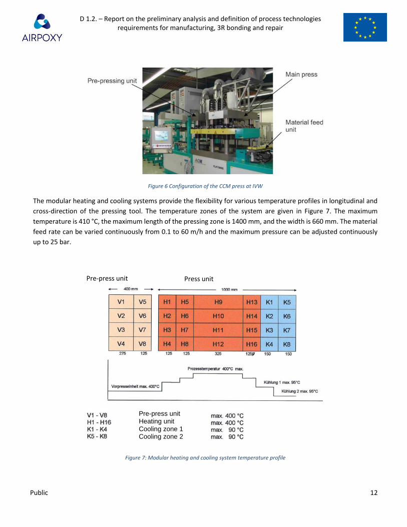
Figure 6 Configuration of the CCM press at IVW
The modular heating and cooling systems provide the flexibility for various temperature profiles in longitudinal and
cross-direction of the pressing tool. The temperature zones of the system are given in Figure 7. The maximum
temperature is 410 °C, the maximum length of the pressing zone is 1400 mm, and the width is 660 mm. The material
feed rate can be varied continuously from 0.1 to 60 m/h and the maximum pressure can be adjusted continuously
up to 25 bar.
Figure 7: Modular heating and cooling system temperature profile
Pre-press unit Press unit
Pre-press unit Heating unit Cooling zone 1 Cooling zone 2

D 1.2. – Report on the preliminary analysis and definition of process technologies requirements for manufacturing, 3R bonding and repair
Public 13
To prevent adhesion of the molten thermoplastic to the mold halves, the material is transferred through the system
between two release surfaces. Depending on the process temperature, paper, foil, or sheet steel is used.
Furthermore, the release surfaces serve as transportation aids.
3.1.3. Induction welding
IVW has extensive experience in induction welding of thermoplastic fiber reinforced polymer composites (TP-FPRC)
to TP-FRPC but also in welding metals to TP-FRPC. Furthermore there were some studies in welding thermoset FRPC
(TS-FRPC) to TS-FRPC by using thermoplastic surface layers. Manufacturing processes involving the induction welding
developed by IVW are related to the aeronautic, automotive, engineering and other industries. Major tasks in the
welding process development are heating and cooling strategies, process control strategies as well as consolidation
strategies. In welding hybrid structures extensive studies were performed to find the most suitable surface pre-
treatment of the metallic joining partners in order to achieve high bond strengths. In the facilities of IVW are three
induction welding test rigs, explained in more detail below.
Materials and physics
If carbon fiber reinforced polymers are welded, the fibers can be used as heating elements, since they are electrically
conductive. If no joining partner is electro conductive, a welding filler material (susceptor) placed between the joining
partners which absorb the electromagnetic fields and thus heats up and can be used for indirect heating of the TP-
FRPC. Inductive heating is significantly influenced by various physical effects. In induction welding the following three
effects are relevant. The Biot-Savart law, which defines the magnetic field strength at a point in the area around the
inductor, the skin effect, which describes the current density distribution in the conductor, and the edge effect, which
states that heating at the edges of the component can lead to overheating.
In order to guarantee a high power-input into the joining partners, a short distance between induction coil and joining
partners is necessary. To minimize process time, the joining partners are cooled e. g. by forced convection with
compressed air after heating.
In the molten state, the polymer wets the surface of the joining partner and forms the connection mechanisms after
cooling. The simultaneous application of a consolidation force on the welding zone improves a complete wetting of
the surface by the polymer.
Induction heating test rig
In order to investigate the heating behaviour of materials by induction, test specimens can be mounted vertical in an
induction heating test rig shown in Figure 8. The experiments can be conducted e.g. by means of a circular pancake
coil with a diameter of 25 mm and a coil-laminate distance of 5 mm. As induction generator a CEIA Power Cube PW3-
32/400 is used. The maximum temperatures of the surfaces of the specimens can be measured by means of two TIM
160 infrared cameras from MICRO-EPSILON with a field of view of 48°. Both infrared cameras are connected with a
YOKOGAWA recorder GP20 to enable the recording of the measurement. The measurement of the maximum
temperatures of the two surfaces starts automatically once the induction generator is operating. Hence, the different
heating rates of the induction coil faced surface and the opposite surface can be determined. The infrared camera
D 1.2. – Report on the preliminary analysis and definition of process technologies requirements for manufacturing, 3R bonding and repair
Public 14
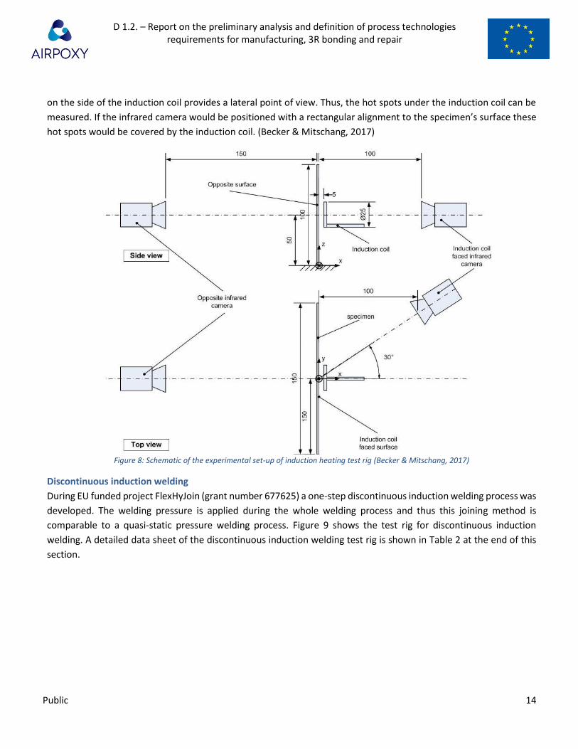
on the side of the induction coil provides a lateral point of view. Thus, the hot spots under the induction coil can be
measured. If the infrared camera would be positioned with a rectangular alignment to the specimen’s surface these
hot spots would be covered by the induction coil. (Becker & Mitschang, 2017)
Figure 8: Schematic of the experimental set-up of induction heating test rig (Becker & Mitschang, 2017)
Discontinuous induction welding
During EU funded project FlexHyJoin (grant number 677625) a one-step discontinuous induction welding process was
developed. The welding pressure is applied during the whole welding process and thus this joining method is
comparable to a quasi-static pressure welding process. Figure 9 shows the test rig for discontinuous induction
welding. A detailed data sheet of the discontinuous induction welding test rig is shown in Table 2 at the end of this
section.
D 1.2. – Report on the preliminary analysis and definition of process technologies requirements for manufacturing, 3R bonding and repair
Public 15
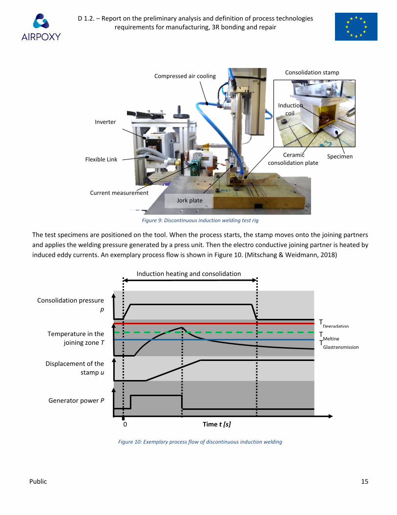
Figure 9: Discontinuous induction welding test rig
The test specimens are positioned on the tool. When the process starts, the stamp moves onto the joining partners
and applies the welding pressure generated by a press unit. Then the electro conductive joining partner is heated by
induced eddy currents. An exemplary process flow is shown in Figure 10. (Mitschang & Weidmann, 2018)
Figure 10: Exemplary process flow of discontinuous induction welding
Specimen
Current measurement
Inverter
Jork plate
Compressed air cooling Consolidation stamp
Flexible Link Ceramic
consolidation plate
Induction coil
Induction heating and consolidation
Generator power P
Displacement of the stamp u
Temperature in the joining zone T
Consolidation pressure p
Time t [s] 0
TDegradation
TMelting
T
Glastransmission

D 1.2. – Report on the preliminary analysis and definition of process technologies requirements for manufacturing, 3R bonding and repair
Public 16
A ceramic consolidation plate is placed between the metal sample and the induction coil. The consolidation plate is
working as an isolation plate. The electro conductive joining partner is heated efficiently, as the ceramic is permeable
to the electromagnetic fields and no energy losses occur. During process, the temperature in the welding zone, the
consolidation pressure and the compaction displacement of the joining partners are supervised. The temperature
during welding is monitored by a thermocouple located in the welding zone or an IR-camera supervising the coil
faced surface of the joining partner. (Mitschang & Weidmann, 2018)
Table 2: Technical description of induction welding test rig
Generator power < 10 kW
Generator frequency 50 – 450 kHz
Generator current < 35 A
Generator Trumpf Hüttinger TrueHeat HF 5010
Coupling distance (for flat samples, for 3D structures the coupling distance have to be adapted on 3D geometry) 0 - 20 mm
Distance between consolidation roller and inductor < 250 mm
Feed max. 5 m/min
Roller width / Max. welding area Depends on induction coil and consolidation stamp
Roller/Stamp tempering No/ To be developed
Consolidation force < 800 N / < 300 N for continuous welding
Induction coil Depends on application
Tempered tool No/ To be developed
Heating rate Depends on material and generator power
Part cooling Compressed air: < 480 nl/min
Process monitoring
IR camera, pyrometer, load cell, displacement sensor, air flow valve for cooling, temperature control by thermocouples, current measuring
Set up of test rig Discontinuous induction welding Continuous induction welding
Continuous induction welding
The continuous induction welding process was developed at Institut für Verbundwerkstoffe GmbH (IVW) (Figure 11).
The welding equipment for this process comprises an induction coil, a consolidation roller and an optical temperature
measurement device. Through a movement of the induction coil relative to the joining partners, the heat is generated
step-by-step along the welding seam in process direction. Once the induction coil has heated the polymer in the
welding zone above the melting temperature, the water-cooled consolidation roller applies the consolidation
pressure and cools down the laminate around the contact area. The distance between the induction coil and the
consolidation roller (b) is fixed during the welding process. By means of the optical temperature measurement device
which is mounted behind the consolidation roller an online monitoring system is provided. (Becker & Mitschang,

D 1.2. – Report on the preliminary analysis and definition of process technologies requirements for manufacturing, 3R bonding and repair
Public 17
2017)
Figure 11: Schematic representation of the assembly of the continuous induction welding process
In order to implement the relative movement two possible strategies for process design are feasible. One
assembly strategy provides the movement of the joining partners. In this case the welding equipment is fixed. The
other process design variant provides the movement of the welding equipment, whereas the joining partners are
fixed.
The continuous induction welding process provides benefits, e. g. a high flexibility and mobility, as well as the
possibility to join complex components. One major drawback, which comes along with the induction heating, is the
unfavourable temperature distribution in thickness direction of the upper joining partner. Due to the distribution of
the field intensity of the electro-magnetic field the melting temperature of the polymer is attained first on the surface
which is faced to the induction coil. Shortly thereafter the polymer in the welding zone attains the melting
temperature. Since the surface faced to the induction coil is molten, the application of the consolidation pressure by
the consolidation roller is impaired. Consequently, delamination or degradation of the polymer can occur.
At IVW are two set ups for continuous induction welding are available, first by an adjustment of the discontinuous IJ
test rig (Figure 9 and Figure 12)and second by a welding robot (Figure 13). The welding robot data sheet is shown in
Table 3. (Mitschang & Velthuis, 2008)
By adjustment of the discontinuous IJ welding test rig the set up shown in Figure 12 an be realized. The generator is
the same as that used in discontinuous induction welding, after adjustment of the test rig by using another pressing
unit, a maximum consolidation force of 300 N is possible.
Joining partners

D 1.2. – Report on the preliminary analysis and definition of process technologies requirements for manufacturing, 3R bonding and repair
Public 18
Figure 12: Continuous induction welding test rig (2 Dimensional)
Continuous induction welding can also be carried out on a welding robot shown in Figure 13. In contrast to the
laboratory test rig, the robot can also weld three-dimensional structures. A detailed data sheet of the continuous
induction welding robot is shown in Table 3 at the end of this chapter.
Induction coil
Tool
Infrared camera
Consolidation roller
Adherend
Surface cooling

D 1.2. – Report on the preliminary analysis and definition of process technologies requirements for manufacturing, 3R bonding and repair
Public 19
Figure 13: Continuous induction welding robot
Table 3: Technical description of induction welding robot
Generator power < 5 kW
Generator frequency 400 kHz
Coupling distance for flat samples, for 3D structures the coupling distance have to be adapted on 3D geometry) 0 - 10 mm
Distance between consolidation roller and inductor < 70 mm
Feed Max. 5 m/min
Max. welding width Roller width: 25 und 50 mm
Roller tempering from 23 °C to 90° C
consolidation force < 400 N
Induction coil Variable
Heated tooling plate < 300°C
Heating rate Depends on material
Part cooling Compressed air: 350 nl/min
Process monitoring IR camera, pyrometer, force control, distance sensor, air flow valve for cooling
Robot
Induction welding head
Clamping jig
Induction coil
Consolidation roller
Infrared camera

D 1.2. – Report on the preliminary analysis and definition of process technologies requirements for manufacturing, 3R bonding and repair
Public 20
3.2. EIRECOMPOSTIES (EIRE)
ÉireComposites is responsible for the induction welding of the leading-edge demonstrator, thermoforming of the
webs and longitudinal stiffener as shown in the Figure 1. This will require the use of ÉireComposites induction welding
and thermoforming expertise which is presented in the following section.
3.2.1. Induction Welding
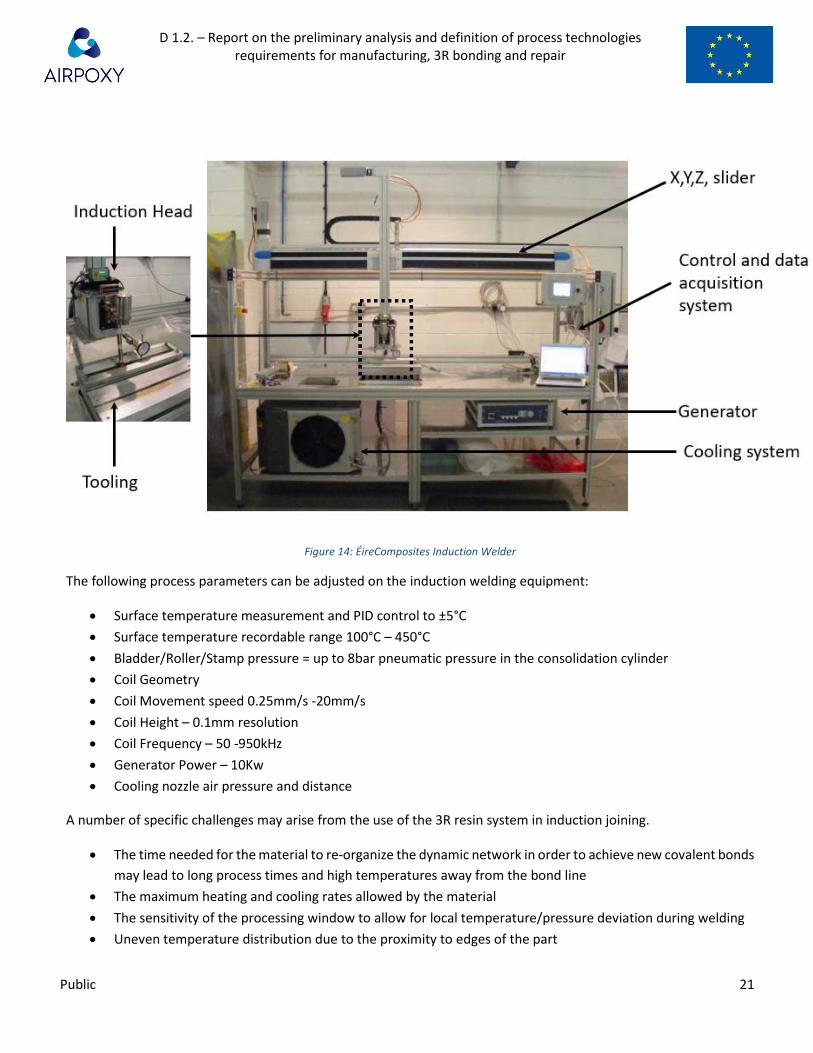
The induction welding equipment at ÉireComposites is shown in Figure 14. A Trumpf Hüttinger HF5010, 10KW high
frequency induction generator is used in conjunction with the induction head to produce a high frequency current in
a copper coil which is held above the work piece. The coil induces a current in electrically conductive materials, in
this case carbon fibers, which heats up by means of electric resistance losses. The heat generated melts the matrix
material in the composite allowing the two elements to fuse. The process temperature is controlled using a
pyrometer which is linked to a PID controller. This modulates the voltage and current in the generator to maintain a
constant top surface temperature during the process. The top surface temperature can then be correlated to the
desired bond line temperature of the part. During welding the temperature of the weldline and in the area
surrounding the weldline is very important. The temperature at the weldline must be sufficient to allow the welding
process to occur while the temperature away from the weldline must be limited to avoid defects such as
deconsolidation, fiber buckling or excessive resin pushout. To control the temperature away from the weldline, high
pressure, room temperature, air jets may be aimed at the surface of the parts during the welding operation. This
method has been shown to help eliminate defects in welding materials such as carbon fiber PEEK and PEKK. Pressure
can be applied using a roller, a stamp or a bladder and each have specific advantages in different cases. For pressure
application with a roller the pressure is applied just after heating by the induction coil. For pressure application with
the stamp or bladder the pressure is applied to the entire weld area before the welding process begins and is
maintained for the entire process. ÉireComposites has developed procedures for welding thermoplastic composites
such as CF-PEEK, CF-PEKK, GF-PEKK (with the use of susceptor) GF-PP (with the use of a susceptor).
D 1.2. – Report on the preliminary analysis and definition of process technologies requirements for manufacturing, 3R bonding and repair
Public 21
Figure 14: ÉireComposites Induction Welder
The following process parameters can be adjusted on the induction welding equipment:
• Surface temperature measurement and PID control to ±5°C
• Surface temperature recordable range 100°C – 450°C
• Bladder/Roller/Stamp pressure = up to 8bar pneumatic pressure in the consolidation cylinder
• Coil Geometry
• Coil Movement speed 0.25mm/s -20mm/s
• Coil Height – 0.1mm resolution
• Coil Frequency – 50 -950kHz
• Generator Power – 10Kw
• Cooling nozzle air pressure and distance
A number of specific challenges may arise from the use of the 3R resin system in induction joining.
• The time needed for the material to re-organize the dynamic network in order to achieve new covalent bonds
may lead to long process times and high temperatures away from the bond line
• The maximum heating and cooling rates allowed by the material
• The sensitivity of the processing window to allow for local temperature/pressure deviation during welding
• Uneven temperature distribution due to the proximity to edges of the part

D 1.2. – Report on the preliminary analysis and definition of process technologies requirements for manufacturing, 3R bonding and repair
Public 22
3.2.2. Thermoforming
Thermoforming equipment at ÉireComposites consists of the hydraulic press and separate infra-red heating system
shown in Figure 15. A pre-consolidated sheet is placed on a sheet of release film and moved into position under and
infrared heater. Once the sheet has reached the target temperature it is quickly transferred between the pre-heated
platens of the press. The platens are closed, and the final shape of the part is formed. Depending on the material the
heated platens may need to be cooled in order to solidify the component. Thermoforming may also be carried out
using the press for heating. For each part geometry to be thermoformed, separate tooling will be manufactured.
ÉireComposites has experience in the production of CF thermoplastic parts using this system. The 3R resin can be
thermoformed but the process parameters such as dwell time and tooling temperature have to be defined.
Figure 15: Heated hydraulic press used for thermoforming and press consolidation
The following parameters can be adjusted on the thermoforming process:
• Heating rate 1°C/min – 10°C/min
• Heating dwell time
• Platen temperature - ±5°C
• Forming pressure – 0 to 180bar
• Cooling steps – Dependent on tooling used
3.3. University of Ioannina (UOI)
In WP4 UOI will develop and implement different Structural Health Monitoring (SHM) techniques at matrix,
composite and modelled structure levels, in order to assess:
i. The knock down effect of the 3R resin components in relation to the conventional resin

D 1.2. – Report on the preliminary analysis and definition of process technologies requirements for manufacturing, 3R bonding and repair
Public 23
ii. The knock down effect of the 3R resin structures in relation to the production processes and bonding techniques
iii. The repair efficiency of the 3R resin components
The results will be evaluated and benchmarked for the optimization of the different repairing conditions which will
be developed from IVW. In addition, the results will be used in WP5 for the implementation of SHM methods and
repair techniques for the two demonstrators. The specifications and processes of each SHM method are described
below.
3.3.1. Acoustic Emission (AE)
This method will be implemented in real time (online) at all levels in order to classify and identify AE signals (hits) at
each of the above cases. The AE activity will be recorded using one or two wide band AE sensors or micro-sensors (R-
15-ALPHA) that will be adapted on the upper side of the specimen (Figure 16). A layer of ultrasonic gel will be applied
between the sensors and the specimen to provide acoustic coupling. A pre-amplifier gain and a threshold will be set
to 40 dB in order to avoid the possibility of electronic/environmental noise. The signals will be recorded by a two-
channel monitoring board PCI-2, PAC with a sampling rate of 5 MHz.
Figure 16. Implementation of acoustic emission on Mode-I test.
3.3.2. IR-Thermography (IR-T)
This method will be implemented online and offline at all levels in order to identify micro-cracks or micro-
delaminations (Figure 17). An IR-camera will be used with the following characteristics:
• Waveband: 3-5 μm
• Resolution: 640x520 pixels
• Frame rate: 4.175-125 Hz
• Pitch detector: 15μm

D 1.2. – Report on the preliminary analysis and definition of process technologies requirements for manufacturing, 3R bonding and repair
Public 24
Figure 17. Online IR-T measurement of TDCB specimen under mechanical loading.
3.3.3. Ultrasonics
The Ultrasonics technique (Figure 18) will be applied for monitoring the heating-cooling cycles of the 3R resin thus
simulating the repair process of the resin. This method will determine the changes of the ultrasound propagation
properties (i.e. velocity, attenuation, etc.) after every heating-cooling cycle of the 3R resin. These properties are
correlated to the elastic modulus of the material. Therefore, the measurement of the ultrasonic propagation
properties will lead to the quantification of the elastic modulus of the material when subjected to a thermal process
(i.e. thermoforming).
The experimental setup will be designed for through-transmission propagation of the ultrasound. The resin will be
poured between two 5 mm thick metal plates. One sensor, acting as pulser, will be mounted on one side, while the
receiving transducer will be placed on the exactly opposite position. The employed piezoelectric sensors (R15a, by
Physical Acoustics Corporation) are sensitive to a quite broad band of frequencies, i.e. from 50 kHz to 800 kHz. The
pulser will be connected to a waveform generator (AFG3102, by Tektronix) which will introduce a cycle of 500 kHz,
at a constant time interval of 30 s.
Figure 18. Ultrasonic experimental setup for monitoring the heating-cooling cycles of the 3R resin.
3.3.4. Electrical Resistance Change Method
The aim of the Electrical Resistance Change test is to identify differences induced by the repair process on the
signature electrical profiles of the specimens in order to evaluate their repair efficiency (Figure 19). This method will

D 1.2. – Report on the preliminary analysis and definition of process technologies requirements for manufacturing, 3R bonding and repair
Public 25
evaluate the resistance of each specimen before and after repair and the sensitivity of the resistance change during
mechanical testing where it will be applicable (e.g. Mode-I test). This will provide an additional indicator in relation
to the repair efficiency of the 3R composite specimens.
The Electrical Resistance Change measurements will be employed by using an Agilent 34401A6 multimeter online
during mechanical tests. The 2-probe method will be applied where the cables will be coupled with the specimens
using conductive silver paste to minimize contact resistance and achieve high electrical coupling. The cables will be
coupled on the two opposite sides of the composites near the repair area.
Figure 19. Experimental device for mechanical testing with simultaneous measurement of electrical resistance.
3.3.5. Impedance Spectroscopy (IS)
Impedance measurements will be implemented using the Advanced Dielectric Thermal Analysis System (DETA-
SCOPE) supplied by ADVISE, Greece. A sinusoidal voltage of 10 V will be applied to the capacitor. Scans will be
performed between two frequency values, 0.01 Hz to 100 kHz. For this purpose, the existing equipment will operate
at higher frequencies, i.e. up to 7 MHz so as to be able to monitor resonances for more conductive materials. All
measurements will be performed under stable temperature that will be controlled by an EXTECH VIR50 IR
thermometer.
Impedance spectroscopy will be utilized:
1. For monitoring the electrical properties of the 3R resin over multiple heating-cooling cycles. An interdigital
capacitor will be introduced inside the resin. Temperature will be controlled by a heating cell (Figure 20).
D 1.2. – Report on the preliminary analysis and definition of process technologies requirements for manufacturing, 3R bonding and repair
Public 26
Figure 20. Impedance spectroscopy setup for heating-cooling cycle measurements.
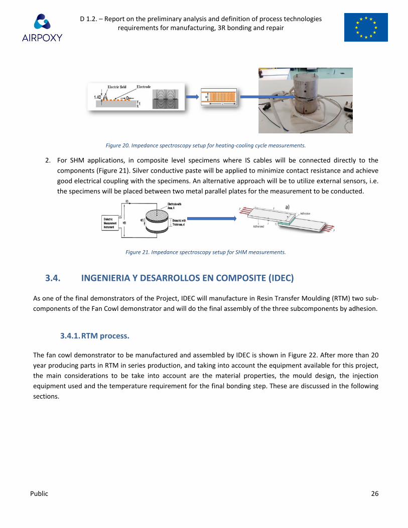
2. For SHM applications, in composite level specimens where IS cables will be connected directly to the
components (Figure 21). Silver conductive paste will be applied to minimize contact resistance and achieve
good electrical coupling with the specimens. An alternative approach will be to utilize external sensors, i.e.
the specimens will be placed between two metal parallel plates for the measurement to be conducted.
Figure 21. Impedance spectroscopy setup for SHM measurements.
3.4. INGENIERIA Y DESARROLLOS EN COMPOSITE (IDEC)
As one of the final demonstrators of the Project, IDEC will manufacture in Resin Transfer Moulding (RTM) two sub-
components of the Fan Cowl demonstrator and will do the final assembly of the three subcomponents by adhesion.
3.4.1. RTM process.
The fan cowl demonstrator to be manufactured and assembled by IDEC is shown in Figure 22. After more than 20
year producing parts in RTM in series production, and taking into account the equipment available for this project,
the main considerations to be take into account are the material properties, the mould design, the injection
equipment used and the temperature requirement for the final bonding step. These are discussed in the following
sections.

D 1.2. – Report on the preliminary analysis and definition of process technologies requirements for manufacturing, 3R bonding and repair
Public 27
Figure 22: Fan Cowl demonstrator component
3.4.2. Material.
Fibres
As the geometry of the parts is quite complex, a five Harness Satin construction of the woven fibres (Figure 23) is
necessary in order to preform the layers properly and achieve a good drapability.
Figure 23: Five Harness Satin Weave.
Binder / Veil
As a demonstrator of an industrial process, the fibre should be powdered by epoxy or thermoplastic binder or veils,
in order to be activated during a hot-forming process. Activation temperature of this binder should not be higher
than 180C. It is imperative to assure the compatibility between the binder or veil and the 3R resin.
Resin
Resin viscosity at injection temperature (80°C approx.) should be lower than 30 cps in order to achieve a good
impregnation of the fibres and avoid porosity and voids.
Skin (s) Longitudinal Stiffener (ls)
Transverse Stiffener (ts)

D 1.2. – Report on the preliminary analysis and definition of process technologies requirements for manufacturing, 3R bonding and repair
Public 28
3.4.3. Moulds
Injection moulds will be made of steel in order to ensure a good quality of the part from the point of view of
delaminations, surface quality, volume tolerances (0.2 mm), etc.
If necessary, auxiliary tools for preforms can be made of other materials like epoxy or aluminium. However, they
must withstand the binder activation temperature, that can be from 80 - 100C in the case of the already Airbus
qualified binder E01, to 170C in case of V800 thermoplastic veil of HiTape UD material.
3.4.4. Injection Equipment
IDEC can handle both mono & bi-component resins. In case of monocomponent resin, the injection machine can
regulate the injection pressure. In case of bicomponent, the injection machine can regulate the injection resin flow
from 100cc/min to 400 cc/min with a control of the maximum pressure applied.
In both cases maximum injection pressure is 10 bar.
Usually, the injection process temperature is about 80-120°C. If process temperature is below 140°C, in principle it
can be performed without serious modifications of the equipment.
3.4.5. Adhesion Process
Adhesives have been used extensively for structural bonding applications in aerospace. Epoxy resins are widely used
as adhesives for bonding in the manufacture of aircraft parts. Compared to mechanically fastened joints, bonded
joints, they weigh less because of a reduced number of parts, and they give a more uniform distribution of stresses
along the joint.
Aerospace structural adhesives have to meet better mechanical specifications together with tougher environmental
and safety criteria. In this sense 3R film adhesives offer the possibility to create covalent bonds with 3R composites
to achieve high performance joints.
In AIRPOXY project new adhesion process will be studied for bonding the three elements of the fan cowl. For that
purpose a 3R film adhesive will be formulated and manufactured according to specifications defined in WP1.
For the bonding process the following aspects will be defined:
D 1.2. – Report on the preliminary analysis and definition of process technologies requirements for manufacturing, 3R bonding and repair
Public 29
- Bonding is improved when some mechanical interlocking exists between the adhesive and small
irregularities on the surfaces of the materials to be joined. In this sense in order to have a rough surface a
peel ply will be introduced in the parts that will be latter bonded by 3R film adhesive.
- For the adhesion process of different parts the curing temperature will not reach their Glass
Transition Temperature (Tg) that should be around 170°C for aeronautic applications to avoid any distortions
in the parts. IDEC has capability to apply heat in an oven up to 200°C.
- The adhesive film must be able to fill a gap of 0.3mm between the elements.
After application of the adhesive, the parts to be bonded should be carefully aligned in the designed configuration.
They are usually held in place with clamps or some equivalent mechanical restraining device. The parts should then
remain in this fixed position until after the adhesive has solidified.
3.5. SOCIETE NATIONALE DE CONSTRUCTION AEROSPATIALE SONACA (SON)
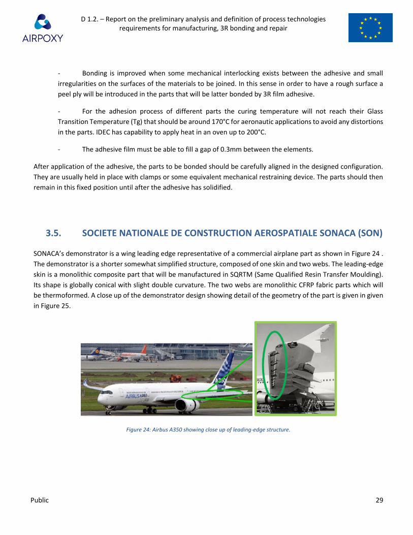
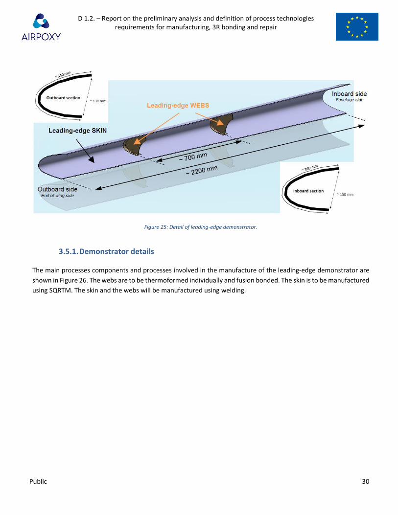
SONACA’s demonstrator is a wing leading edge representative of a commercial airplane part as shown in Figure 24 .
The demonstrator is a shorter somewhat simplified structure, composed of one skin and two webs. The leading-edge
skin is a monolithic composite part that will be manufactured in SQRTM (Same Qualified Resin Transfer Moulding).
Its shape is globally conical with slight double curvature. The two webs are monolithic CFRP fabric parts which will
be thermoformed. A close up of the demonstrator design showing detail of the geometry of the part is given in given
in Figure 25.
Figure 24: Airbus A350 showing close up of leading-edge structure.
D 1.2. – Report on the preliminary analysis and definition of process technologies requirements for manufacturing, 3R bonding and repair
Public 30
Figure 25: Detail of leading-edge demonstrator.
3.5.1. Demonstrator details
The main processes components and processes involved in the manufacture of the leading-edge demonstrator are
shown in Figure 26. The webs are to be thermoformed individually and fusion bonded. The skin is to be manufactured
using SQRTM. The skin and the webs will be manufactured using welding.

D 1.2. – Report on the preliminary analysis and definition of process technologies requirements for manufacturing, 3R bonding and repair
Public 31
Figure 26: Components and processes involved in manufacturing the final demonstrator.
3.5.2. Thermoforming of webs
The two webs are made of CFRP + GFRP fabric with a 3R resin matrix. Each web is made of two half parts that will be
thermoformed independently and fusion bonded together. The two webs (and therefore the four half webs) are
different from each other due to the conical shape of the leading-edge skin and because of this separate tooling will
be required for the manufacture and assembly of each web. The approximate thickness of each half web is 1.25mm.
Each half-web shall be made of 4 carbon fabric plies or orientation [0°, 45°, 90°, -45°] with the -45° ply being the
outermost ply and one glass fiber fabric ply on the external surface.
Images of the final web which show the overall geometry the layup directions and a section view of the bond between
the skin and the web are given in Figure 27.

D 1.2. – Report on the preliminary analysis and definition of process technologies requirements for manufacturing, 3R bonding and repair
Public 32
Figure 27: Left - image of final web. Centre - Drawing defining layup direction. Right - section view of fusion bond to skin showing geometry of
join including noodle filler.
The thermoforming process of the webs will be developed in WP2 by IVW and implemented in WP5 by EIRE for the
forming of the final webs. The DCM process will be used for the thermoforming of the Webs. Discontinuous
Compression Molding is a process in which the material is hot formed / compression molded in one or several
discontinuous steps. During the thermoforming process, the cured 3R laminates or laminates will be brought to 230-
240°C in order to permit the reorganization of the dynamic covalent bonds inside the 3R resin.
It should be noted that the fibers play an important role in the thermoforming process. As with any thermoforming
process the fibers may restrict the geometry of the final part. Partners involved in the development of the
thermoforming process will assess the feasibility of forming the final part as investigated and potential changes to
the process or the geometry will be investigated. If necessary alternative process or materials will be discussed.
Several routes for production of the webs are presented in Figure 28.

D 1.2. – Report on the preliminary analysis and definition of process technologies requirements for manufacturing, 3R bonding and repair
Public 33
Figure 28: Methods of producing the thermoformed half web
Route 1a – RTM + DCM
This route plans on manufacturing 3R flat panels through the RTM process. The 3R flat laminate is then thermoformed
through the Discontinuous Compression Molding process (DCM).
This route is not the one preferred by SONACA as it requires to use the RTM process (which is still time consuming
and expensive although an OOA process) before the thermoforming itself. It is therefore probably not the best
solution for industrial process.
Routes 2a & 2b – Enduring prepreg
These manufacturing routes plan on producing 3R enduring prepregs.
Route 2a will investigate consolidation (with hot press for example) of unconsolidated 3R enduring prepreg in order
to produce 3R flat panels followed by the DCM thermoforming process.
Route 2b, will investigate consolidation and thermoforming in one DCM process. If successful, this solution would be
the most interesting as it is the one using the less intermediary processes.
3.5.3. SQRTM injection of skin
The base-line lay-up of the leading-edge skin will be made of the following layers (see Figure 29):
• External metallic facing. This 0.4mm metallic sheet is co-bonded with the rest of the lay-up during the SQRTM process and is here as a protection against erosion.
• Hybrid lay-up. This hybrid lay-up is composed of structural CFRP Uni-directional plies, dielectric GFRP fabric plies and an embedded electrical resistance for the de-icing.
• Internal surface 3R adhesive film. The 3R adhesive ply is co-cured with the rest of the lay-up during the SQRTM process.
• Internal metallic facing. This 0.4mm metallic sheet is identical to the external one, with openings where the webs are bonded.

D 1.2. – Report on the preliminary analysis and definition of process technologies requirements for manufacturing, 3R bonding and repair
Public 34
Figure 29: Baseline lay-up of skin
In some specific cases, the lay-up may vary, with the removing of the metallic facings and the addition of an expanded
metal foil on the external surface (Figure 30). This secondary lay-up will be made of the following layers:
• Erosion coating: Instead of the metallic facing, a specific coating may play the role of the erosion protection. Its thickness would be around 0.2 mm. This coating would be a dielectric.
• Expanded metal foil: An expanded metal foil is then embedded at the surface of the dielectric plies.
• Hybrid lay-up. This hybrid lay-up is composed of structural CFRP Uni-directional plies, dielectric GFRP fabric plies and an embedded electrical resistance for the de-icing.
• Internal surface 3R adhesive film. The 3R adhesive ply is co-cured with the rest of the lay-up during the SQRTM process.
Figure 30: Alternative layup sequence for skin
The final demonstrators’ skins will be manufactured using SQRTM by SONACA in WP5.
As part of WP3 COEXPAIR will perform the development tests in order to define the SQRTM parameters for the
manufacturing of laminates with high 3R adhesive content on the surface. The 3R adhesive on the surface of the
laminates will permit the welding between the webs and the skin.
Compared to the traditional RTM, the SQRTM uses prepreg and can therefore benefit from the tough resins. The
laminate being already impregnated, the injection resin is here to put pressure on the preform and guarantee the
good conditions required for the curing. Although the injection resin is not supposed to diffuse inside the laminate,
the same resin as the prepreg is still used for the injection in order to prevent resin incompatibility that might
decrease the performance of the prepreg in case of involuntary mixing.
Explanations on the SQRTM process and its advantages/disadvantages are given in .

D 1.2. – Report on the preliminary analysis and definition of process technologies requirements for manufacturing, 3R bonding and repair
Public 35
Figure 31: Overview of the SQRTM process showing pro's and con's
3.5.4. Welding of Webs to skin
After the thermoforming of the four half-webs, they shall be assembled with the noodle fillers in order to form
complete webs. Following this the two webs will be welded with the skin as part of the final process. The webs are
manufactured with 3R material and the skin is manufactured with a 3R adhesive layer on its internal face. The
objective is to weld them by providing enough heat and pressure so that the 3R material of each substrate can fuse
and form covalent bonds. The development of the welding will be carried by IVW in WP3 and transferred to EIRE in
WP5 for the assembly of the webs and the final assembly of the webs and the skin.
4. Conclusion
This document has presented the equipment and processes that will be used for the manufacture of composite
components in industrial environment (WP5) as part of the AIRPOXY project. Details of IVW, EIRE, UOI, IDEC, and
SONACA’s equipment and expertise in process development have been presented.
5. Annex
NA
6. References
[1] AIRPOXY Kick-Off meeting PPT Presentation 5th-6th September, 2018
Becker, S., & Mitschang, P. (20-25. August 2017). INFLUENCES OF TEXTILE PARAMETERS ON THE INDUCTION HEATING
BEHAVIOR OF CFRPC. 21st International Conference on Composite Materials.
D 1.2. – Report on the preliminary analysis and definition of process technologies requirements for manufacturing, 3R bonding and repair
Public 36
Mitschang, P., & Velthuis, R. (2-5. June 2008). PROCESS PARAMETERS FOR INDUCTION WELDING OF
METAL/COMPOSITE JOINTS. Proceedings of ECCM13 Conference, Sweden.
Mitschang, P., & Weidmann, S. (24-28. June 2018). Influence of penetration depth on lap shear strength of induction
welded steel/TP-FRPC joints. ECCM18 - 18th European Conference on Composite Materials.