airworthiness& typecertification airworthinessissues · structural strenght structures...
TRANSCRIPT

Airworthiness &
Type Certification
Airworthiness Issues
Giovanni Di Antonio 2017Pag. 1
Airworthiness IssuesEng. Giovanni Di Antonio
The information contained in this presentation is intended for educational purpose only, it exclusively refect the Author’s ideas and point of view and in some parts may not be completely updated. The content of this presentation has not been formally endorsed neither by the Italian Civil Aviation
Authority (ENAC) nor by the European Aviation Agency (EASA) or other Civil Aviation Authorities. Any implementation of the approaches and methodologies exposed in ths presentation remains under the complete responsibility of the implementer.
Rome, 20 Sep. 2017

SUMMARY
• Structural Strenght & Material Qualification
• Primary Composite Structures
• Fatigue & Damage Tolerance
• Aging Aircraft
• Crashworthiness
Giovanni Di Antonio 2017Pag. 2
• Crashworthiness
• System Safety Assessment
• Systems Structures interaction
• Flammability & Fire Protection
• Lightining Protection

1. Structural Strenght & Materials Qualification
Pag. 3
Materials Qualification

STRUCTURAL STRENGHT
Structures Classifications
Giovanni Di Antonio 2017Pag. 4
Primary Structure – Structure that carries flight, ground, crash or pressurization loads.
Fatigue Critical Structure (FCS) – Structure that is susceptible to fatigue cracking that could lead to a catastrophic failure of an aircraft.
Principal Structural Element (PSE) – Element of a primary structure subject to repeated loading conditions the failure of which could lead to a catastrophic condition
Source: Airbus

STRUCTURAL STRENGHT
SUBPART C – STRENGTH REQUIREMENTS
GENERAL
CS XX.301 Loads
CS XX.303 Factor of safety
CS XX.305 Strength and deformation
CS XX.307 Proof of structure
EMERGENCY LANDING CONDITIONS
CS XX.561 General
FATIGUE EVALUATION
Giovanni Di Antonio 2017Pag. 5
CS XX.571 Fatigue evaluation of flight structure
SUBPART D – DESIGN AND CONSTRUCTION
GENERAL
CS XX.603 Materials
CS XX.605 Fabrication methods
CS XX.609 Protection of structure
CS XX.610 Lightning and static electricity protection
CS XX.613 Material strength properties and design values
CS XX.629 Flutter
STRUCTURAL STRENGHT
Limit Loads (LL) & Ultimate Loads (UL)
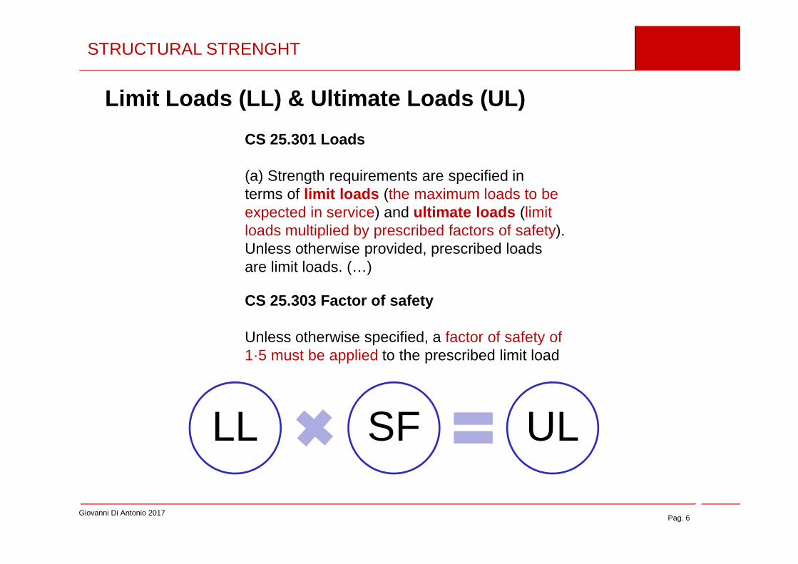
CS 25.301 Loads
(a) Strength requirements are specified interms of limit loads (the maximum loads to beexpected in service) and ultimate loads (limitloads multiplied by prescribed factors of safety).Unless otherwise provided, prescribed loadsare limit loads. (…)
Giovanni Di Antonio 2017Pag. 6
CS 25.303 Factor of safety
Unless otherwise specified, a factor of safety of1·5 must be applied to the prescribed limit load
LL SF UL

STRUCTURAL STRENGHT
Structutal Strenght Req.s
CS 25.305 Strength and deformation
(a) The structure must be able to supportlimit loads without detrimental permanentdeformation. At any load up to limit loads, thedeformation may not interfere with safeoperation.
CS 25.307 Proof of structure
(a) Compliance with the strength anddeformation requirements of this Subpart mustbe shown for each critical loading condition.
Structural analysis may be used only if the
Giovanni Di Antonio 2017Pag. 7
operation.
(b) The structure must be able to supportultimate loads without failure for at least 3seconds. (…)
Structural analysis may be used only if thestructure conforms to that for which experiencehas shown this method to be reliable.
In other cases, substantiating tests must be made toload levels that are sufficient to verify structuralbehaviour up to loads specified in CS 25.305.
(…)

STRUCTURAL STRENGHT
• Req. XX.301LL = Maximum loads expected during operations UL = LL x Safety Factor (SF)
• Req. XX.303SF = 1.5 unless othewise stated
• Req. XX.305
Giovanni Di Antonio 2017Pag. 8
• Req. XX.305 The structures must withstand LL without detrimental permanent deformations and must sustain UL without failure for at least 3 seconds
• Req. XX.307 Req. XX.305 must be verified in all the anticipated operating and environmental conditions

MATERIAL & PROCESS REQUIREMENTS
Material & Processes
XX.603 MaterialSpecifications
XX.605 ProcessSpecification
Giovanni Di Antonio 2017Pag. 9
ProcessesReq.s
XX.605 ProcessSpecification
XX.613 Design Values

CS 25.603 Materials
The suitability and durability of materials usedfor parts, the failure of which could adverselyaffect safety, must –
(a) Be established on the basis ofexperience or tests
MATERIAL QUALIFICATION
Giovanni Di Antonio 2017Pag. 10
(b) Conform to approved specifications ,that ensure their having the strength and otherproperties assumed in the design data
(c) Take into account the effects ofenvironmental conditions , such astemperatureand humidity, expected in service.

CS 25.605 Fabrication methods
(a) The methods of fabrication used mustproduce a consistently sound structure .
If a fabrication process (such as gluing, spotwelding, or heat treating) requires close controlto reach this objective, the process must beperformed under an approved process
MATERIAL QUALIFICATION
Giovanni Di Antonio 2017Pag. 11
specification .
(b) Each new aircraft fabrication methodmust be substantiated by a test programme .
“Consistently” = Able to be reproduced with the same strenght characteristics
“Sound” = Good, Sufficenlty robust

CS 25.613 Material strength properties and Material Design Values
(a) Material strength properties must be based on enough tests of material meeting approved specifications to establish design values on a statistical basis.
(b) Material design values must be chosen to minimise the probability of structural failures due to material variability . (…) compliance must be shown by selecting material design values which assure material strength with the following probability:
(1) Where applied loads are eventually distributed through a single member
MATERIAL QUALIFICATION
Giovanni Di Antonio 2017Pag. 12
(1) Where applied loads are eventually distributed through a single member within an assembly, the failure of which would result in loss of structural integrity of the component, 99% probability with 95% confidence .
(2) For redundant structure , in which the failure of individual elements would result in applied loads being safely distributed to other load carrying members, 90% probability with 95% confidence .
(c) The effects of environmental conditions , such as temperature and moisture,on material design values used in an essential component or structure must be considered where these effects are significant within the aeroplane operating envelope.
A-Basis
B-Basis

XX.613
Testing
Strength
Environment
MATERIAL QUALIFICATION
Giovanni Di Antonio 2017Pag. 13
• Material Design Values. Material strength properties established based on the regulatory requirements . Account for the effects on the operational environment in which the materials operate. Generally Design Values are statistically determined based on enough data that, when used for design, the probability of the structural failure due to material variability will be minimized. Design values are a subset of the aircraft’s type d esign
• Material Allowables – Material strength properties that have been statistically derived from data obtained from tests of materials purchased and processed per acceptable specifications . Unlike material design values, material allowables may or may not account for the operational environment . Temperature and moisture corrections factors may be applied to the material allowables derived from room temperature tests (for economic reasons) to account for the expected environment to form material design values used in aircraft design
Allowables Statistical Basis«A-Basis» vs «B-Basis»
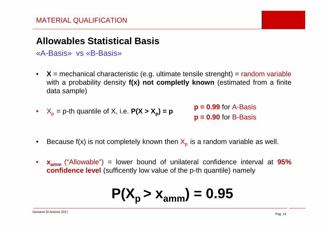
• X = mechanical characteristic (e.g. ultimate tensile strenght) = random variablewith a probability density f(x) not completly known (estimated from a finitedata sample)
• Xp = p-th quantile of X, i.e. P(X > Xp) = p
MATERIAL QUALIFICATION
p = 0.99 for A-Basisp = 0.90 for B-Basis
Giovanni Di Antonio 2017Pag. 14
• Because f(x) is not completely known then Xp is a random variable as well.
• xamm (“Allowable”) = lower bound of unilateral confidence interval at 95%confidence level (sufficently low value of the p-th quantile) namely
P(Xp > xamm) = 0.95
p = 0.90 for B-Basis

MATERIAL QUALIFICATION
Giovanni Di Antonio 2017Pag. 15
Source: Rice R.C., Goode R.J., Bakuckas J.G., Thompson S.R., Development of MMPDS Handbook Aircraft Design Allowables, 7th Joint DOD/FAA/NASA Conference on Aging Aircraft, September 8-11, 2003, New Orleans, LA

2. Primary Composite Structures
Pag. 16

COMPOSITE STRUCTURES – INVESTIGATION AREAS
Material Properties & Fabrication Methods
Static Strenght
Fatigue & Damage Tolerance
Aeroelastic instabilities
Giovanni Di Antonio 2017Pag. 17
Aeroelastic instabilities
Crashworthiness
Flammability & Fire Protection
Lightning Protection
Continued Airworthiness (e.g. Repair Issues)
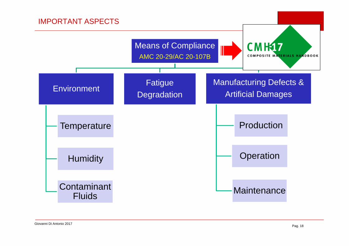
Means of ComplianceAMC 20-29/AC 20-107B
Environment
Temperature
FatigueDegradation
Manufacturing Defects & Artificial Damages
Production
IMPORTANT ASPECTS
Giovanni Di Antonio 2017Pag. 18
Temperature
Humidity
ContaminantFluids
Production
Operation
Maintenance

CERTIFICATION APPROACH
• Risk reduction Incrementalapproach
• Testing on elements of increasing complexity
• Final full -scale test or
BUILDING BLOCK
Giovanni Di Antonio 2017Pag. 19
RTD = Room Temperature Dry
Source: AMC 20-29
Data Base
• Final full -scale test or (HTW or RTW + overload factors)
• Subcomponent test + analysis supported by test evidence at lover level

The following must be defined ….• Material specification• Process specification• Material Properties
….to assure:• Design values reliability • Material reproducibility
COMPOSITE MATERIAL QUALIFICATION
VariabilityMaterial
Process
Giovanni Di Antonio 2017Pag. 20
From DOT/FAA/AR-00/47
[ WARNING ]
EASA does not certify materials and processes however
materials and processes specifications are part of the Type Design subject to type-certification
(AMC 20-29)Source: DOT-FAA-03-19

3. Fatigue & Damage Tolerance
Pag. 21
3. Fatigue & Damage Tolerance
SAFE – LIFE FAIL – SAFE DAMAGE TOLERANCE
SAFE-LIFE
Safe-Life (replacement time) determination
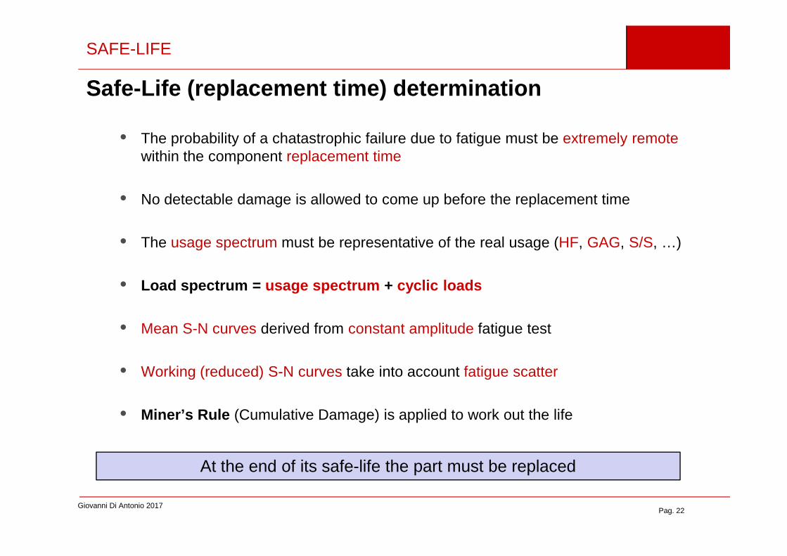
• The probability of a chatastrophic failure due to fatigue must be extremely remote within the component replacement time
• No detectable damage is allowed to come up before the replacement time
• The usage spectrum must be representative of the real usage (HF, GAG, S/S, …)
• Load spectrum = usage spectrum + cyclic loads
Giovanni Di Antonio 2017Pag. 22
• Load spectrum = usage spectrum + cyclic loads
• Mean S-N curves derived from constant amplitude fatigue test
• Working (reduced) S-N curves take into account fatigue scatter
• Miner’s Rule (Cumulative Damage) is applied to work out the life
At the end of its safe-life the part must be replaced

SAFE-LIFE
∑ in
i CONDITION % OF TIME numero di cicli (ni)1 ON GROUND 3,52 APPROACH 53 SPOT-TURN 14 LANDING 1,55 AUTOROTATION 16 TAKE-OFF 1,57 DESCENT 1,58 CLIMB 39 LEVEL FLIGHT 56,510 PULL-UP 0,2211 HOVERING 1012 TRANSITION 4,5213 TURNS 814 SPECIAL TURNS 0,7615 LATERAL FILGHT 2
TOT (FLIGHT HOURS) 100
Giovanni Di Antonio 2017Pag. 23
Source: AC 27-1B Chg 2 MG 11.
∑iiN
d
FHLife
100=
Some weakness
• Usage spectrum not always fullyrepresentative of the real operational use
• The effect of load sequence is not takeninto account
• The effect of the nominal stress belowthe fatigue limit is not considered
• Load survey variability
• Miner Hypotesis ( total damage = 1 ) notalways verified (D = 0.5 – 2)
∑=i
i
N
nd

DAMAGE TOLERANCE (DT)
• Step 1 – damage propagationspeed da/dn = f (∆K) including ∆K threshold and critical value
DT scope
1) To determine by analysis or test the propagation of a damage/defect in a structural
component subjcted to static and/or cyclic loads
2) To define an inspection program to find the damage with high probability before it
reaches its critical size
Giovanni Di Antonio 2017Pag. 24
speed da/dn = f (∆K) including ∆K threshold and critical value
• Step 2 – initial damage size (a0) and detectable damage size (aDET)
• Step 3 – Residual Strenght (RS) and critical defect size aCR
• Step 4 – Inspection interval
Source: FAA, Damage Tolerance Analysis for Antenna Installation on Pressurised Transport Airplanes, Chicago Certification Office
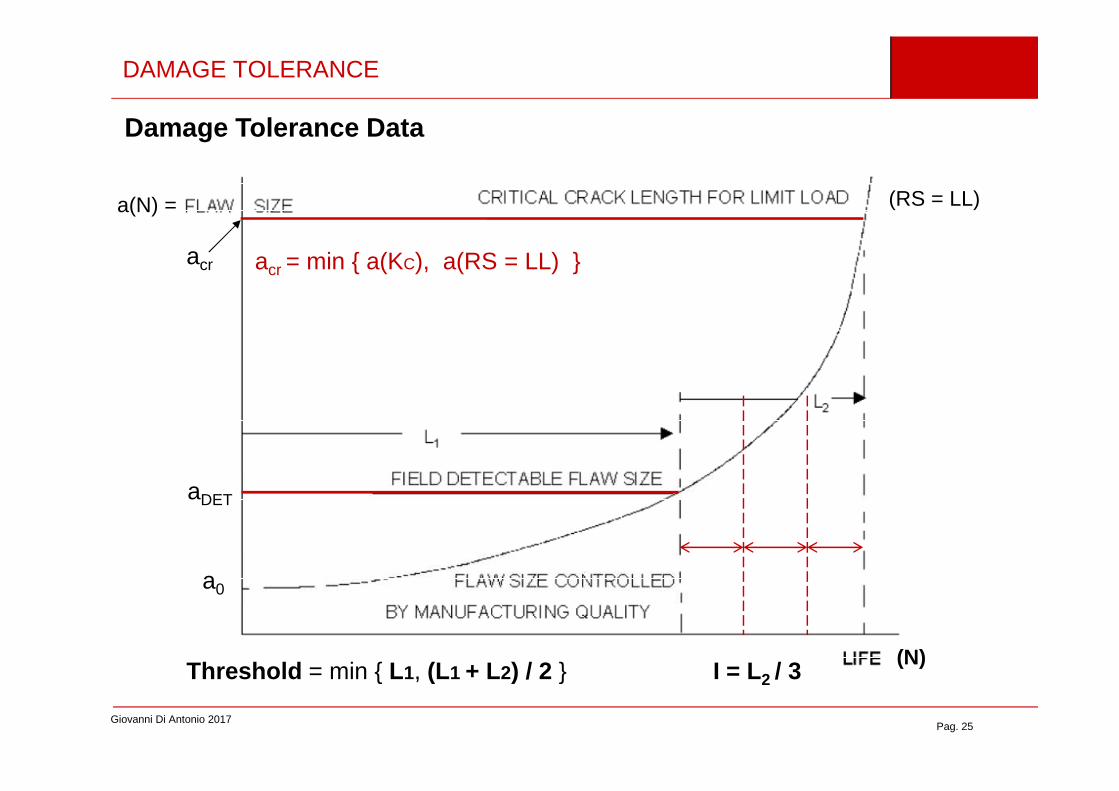
DAMAGE TOLERANCE
acr
(RS = LL)a(N) =
acr = min a(KC), a(RS = LL)
Damage Tolerance Data
Giovanni Di Antonio 2017Pag. 25
I = L2 / 3
aDET
(N)Threshold = min L1, (L1 + L2) / 2
a0

5. Aging Aircraft
Pag. 26
5. Aging Aircraft

AGIN AIRCARFT
ContinuingAircraft Integrity Program
WFD
MED
SSID(DT data)
SBReview
CPCP FCS RepairReview
DSG ≤ LOV
Structural IntegrityAMC 20-20
With the increased use, longer operational lives and experience from in-service aircraft, there is a need for a programme to ensure a high level of structural integrity for all aircraft
Giovanni Di Antonio 2017Pag. 27
MED
MSD
SB = Service BulletinsSSID = Structural Special Inspection DocumentWFD = Widespread fatigue DamageMED = Multiple Element DamageMSD = Multiple Side LocationCPCP = Corrosion Prevention and Control Programme
DT = Damage Tolerance CPCP = Corrosion Prevetion and Control ProgrammeFCS = Fatigue Critical SrtucturesPSE = Primary Structural ElementDSG = Design Service GoalLOV = Limit Of Validity
Limit of validity (LOV) = period of time for which it has been shown (based on fatigue test evidence) that the established inspections and replacement times are sufficient to allow safe operation and to preclude WFD. The LOV and associated actions should be incorporated in the ALS

AGING AIRCRAFT
Widedspread Fatige Damage (WFD)AMC 20-20
• The likelihood of the occurrence of fatigue damage in an aircraft’s structure increases with aircraft usage
• The design process generally establishes a design service goal (DSG) in terms of flight cycles/hours for the airframe
• It is expected that any cracking that occurs on an aircraft operated up to the DSG will occur in isolation (i.e. local cracking), originating from a single source, such as a
Giovanni Di Antonio 2017Pag. 28
will occur in isolation (i.e. local cracking), originating from a single source, such as a random manufacturing flaw (e.g. a mis-drilled fastener hole) or a localised design detail
• It is considered unlikely that cracks from manufacturing flaws or localised design issues will interact strongly as they grow
• With extended usage, uniformly loaded structure may develop cracks in adjacent fastener holes, or in adjacent similar structural details. The development of cracks at multiple locations (both MSD and MED) may also result in strong interactions that can affect subsequent crack growth, in which case the predictions for local cracking would no longer apply.

AGING AIRCRAFT
Ex. skin joint . Load transfer occurs. Simultaneous cracking at many fasteners along a common rivet line may reduce the residual strength of the joint below required levels before the cracks are detectable under the maintenance programmeestablished at time of certification.
MSD
Giovanni Di Antonio 2017Pag. 29
MSD
MED/MSDSource : EASA AMC 20-20

AGING AIRCRAFT
LOV=Limit Of ValidityISP = Initial Inspection PointSMP = Structure Modification Point
Giovanni Di Antonio 2017Pag. 30
Inspection Start Point (ISP) = Point in time when special inspections start due to a specific probability of having MSD/MED. It is determined by a statistical analysis of crack initiation based on fatigue testing, teardown, or service experience of similar structuraldetails. The ISP is equivalent to a lower bound value with a specific probability in the statistical distribution of cracking events.
Structural Modification Point (SMP) = Point reduced from the WFD average behaviour (i.e., lower bound). Operation up to SMP provides equivalent protection to that of a two-lifetime fatigue test. No aircraft should be operated beyond the SMP without modification or part replacement. The SMP can be determined by dividing the WFD Average Behaviour by a factor of 2 if there are viable inspections, or by a factor of 3 if inspections are not viable.
MED/MSD coaleshence
Source : EASA AMC 20-20

6. Crashworthiness
Pag. 31
6. Crashworthiness
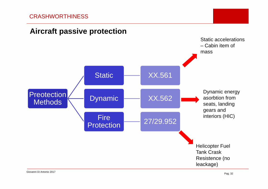
CRASHWORTHINESS
Aircraft passive protection
Preotection
Static XX.561
Dynamic XX.562
Static accelerations– Cabin item of mass
Dynamic energy
Giovanni Di Antonio 2017Pag. 32
PreotectionMethods Dynamic XX.562
FireProtection 27/29.952
Dynamic energyasorbtion from seats, landinggears and interiors (HIC)
Helicopter FuelTank CraskResistence (no leackage)

CRASHWORTHINESS
BirdstrikeCS 25.631 Bird strike damage
The aeroplane must be designed to assurecapability of continued safe flight and landingof the aeroplane after impact with a 4 lb birdwhen the velocity of the aeroplane (relative tothe bird along the aeroplane’s flight path) isequal to VC at sea-level or 0·85 VC at 2438 m(8000 ft), whichever is the more critical.(…)
Giovanni Di Antonio 2017Pag. 33

CRASHWORTHINESS
Landing Gear Drop Test
CS 29.473 Ground loading conditions andAssumptions
(b) Unless otherwise prescribed, for eachspecified landing condition, the rotorcraft must bedesigned for a limit load factor of not less than thelimit inertia load factor substantiated under CS29.725.
Giovanni Di Antonio 2017Pag. 34
CS 29.723 Shock absorption tests
The landing inertia load factor and the reserveenergy absorption capacity of the landing gear must be substantiated by the tests prescribed in CS 29.725 and 29.727, respectively.
These tests must be conducted on the complete rotorcraft or on unitsconsisting of wheel, tyre, and shock absorber in their proper relation.

7. Hazard Analysis & Safety Assessmentof Aircraft Systems
Pag. 35
of Aircraft Systems

Risk = Probability * Consequences
>> SAFETY BARRIES
THE RISK CONCEPT
Giovanni Di Antonio 2017Pag. 36
INTEGRITY LEVEL >>
Source : ASCOS / Internet
SAFETY ASSESSMENT
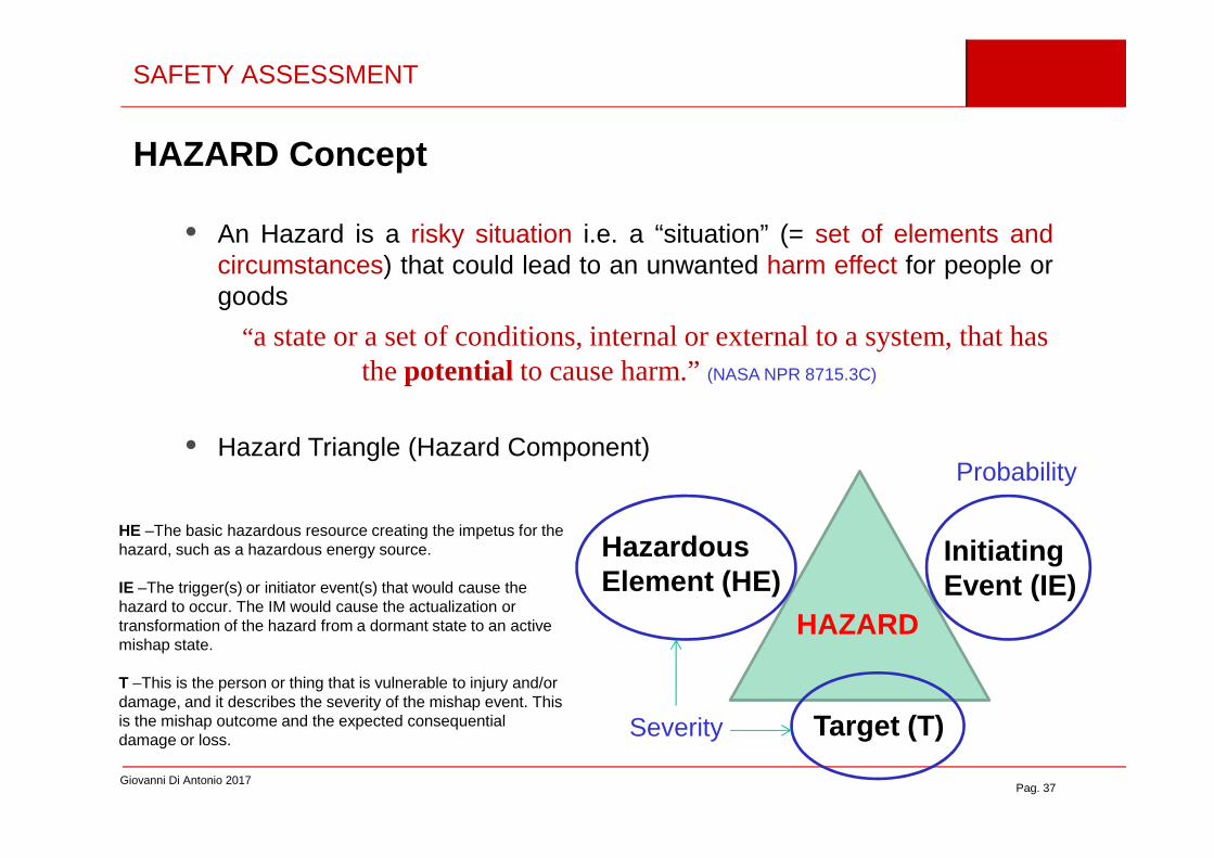
HAZARD Concept
• An Hazard is a risky situation i.e. a “situation” (= set of elements andcircumstances) that could lead to an unwanted harm effect for people orgoods
“a state or a set of conditions, internal or external to a system, that has the potential to cause harm.” (NASA NPR 8715.3C)
•
Giovanni Di Antonio 2017Pag. 37
• Hazard Triangle (Hazard Component)
HAZARD
InitiatingEvent (IE)
HazardousElement (HE)
Target (T)
HE –The basic hazardous resource creating the impetus for the hazard, such as a hazardous energy source.
IE –The trigger(s) or initiator event(s) that would cause the hazard to occur. The IM would cause the actualization or transformation of the hazard from a dormant state to an active mishap state.
T –This is the person or thing that is vulnerable to injury and/or damage, and it describes the severity of the mishap event. This is the mishap outcome and the expected consequential damage or loss.
Probability
Severity
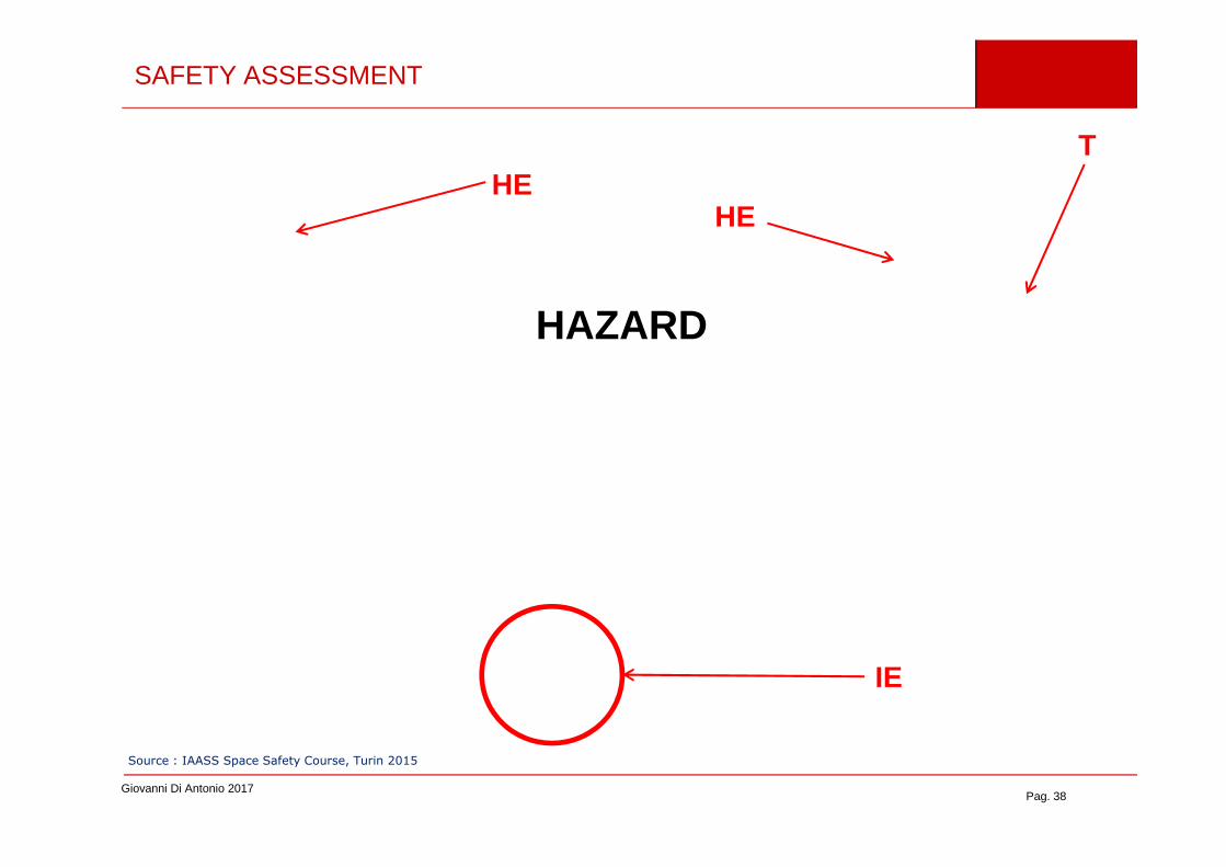
SAFETY ASSESSMENT
HEHE
T
HAZARD
Giovanni Di Antonio 2017Pag. 38
IE
Source : IAASS Space Safety Course, Turin 2015

SAFETY ASSESSMENT
The 1309 requirement
CS 25.1309 Equipment, systems andinstallations
The requirements of this paragraph, except as identified below, are applicable, in addition to specific design requirements of CS-25, to any
(a) The aeroplane equipment and systemsmust be designed and installed so that:
(1) Those required for type
Giovanni Di Antonio 2017Pag. 39
design requirements of CS-25, to any equipment or system as installed in the aeroplane.
Although this paragraph does notapply to the performance and flightcharacteristic requirements of Subpart B and the structural requirements of Subparts C and D, it does apply to any system on which compliance with any of those requirements is dependent. (…)
(1) Those required for typecertification or by operating rules, or whoseimproper functioning would reduce safety,perform as intended under the aeroplaneoperating and environmental conditions.
(2) Other equipment and systems arenot a source of danger in themselves and donot adversely affect the proper functioning ofthose covered by sub-paragraph (a)(1) ofthis paragraph.

SAFETY ASSESSMENT
(b) The aeroplane systems and associated components, considered separately and in relation to other systems, must be designed so that –
(1) Any catastrophic failure condition
(i) is extremely improbable; and(ii) does not result from a single failure; and
Giovanni Di Antonio 2017Pag. 40
failure; and
(2) Any hazardous failure condition is extremely remote; and
(3) Any major failure condition is remote.
(…)

SAFETY ASSESSMENT
Classification of Failure Conditions(Effect SEVERITY)
• No Safety Effect – FC that would not affect the operational capability of theaeroplane or increase crew workload
• Minor – FC which would not significantly reduce aeroplane safety , and whichinvolve crew actions that are well within their capabilities. Minor FC may include,i.e, a slight reduction in safety margins or functional capabilities, a slight increase in
Giovanni Di Antonio 2017Pag. 41
i.e, a slight reduction in safety margins or functional capabilities, a slight increase increw workload, such as routine flight plan changes, or some physical discomfort topassengers or cabin crew.
• Major – FC which would reduce the capability of the aeroplane or the ability of thecrew to cope with adverse operating conditions to the extent that there would be,i.e., a significant reduction in safety margins or functional capa bilities , asignificant increase in crew workload or in conditions impairing crew efficiency,or discomfort to the flight crew, or physical distress to passengers or cabin crew,possibly including injuries
FC = Failure Condition

SAFETY ASSESSMENT
• Hazardous – FC, which would reduce the capability of the aeroplane orthe ability of the crew to cope with adverse operating, conditions to theextent that there would be:
(i) A large reduction in safety margins or functional capabiliti es
(ii) Physical distress or excessive workload such that the flight crewcannot be relied upon to perform their tasks accurately orcompletely; or
Giovanni Di Antonio 2017Pag. 42
completely; or
(iii) Serious or fatal injury to a relatively small number of theoccupants other than the flight crew.
• Catastrophic – FC which would result in multiple fatalities, usuallywith the loss of the aeroplane
FC = Failure Condition

SAFETY ASSESSMENT
ProbabilisticTerminology
Qualitative Description Safety Target ( p = Prob. / FH )
PROBABLEFC anticipated to occur one or more times during the entire operational life of each aeroplane
p > 1E-5
REMOTE
FC unlikely to occur to each aeroplaneduring its total life, but which may occur several times when considering the total operational life of a number of aeroplanes of the type.
1E-7 < p ≤ 1E-5
Giovanni Di Antonio 2017Pag. 43
aeroplanes of the type.
EXTREMELY REMOTE
FC not anticipated to occur to each aeroplane during its total life but which may occur a few times when considering the total operational life of all aeroplanesof the type.
1E-9 < p ≤ 1E-7
EXTREMELYIMPORBABLE
FC so unlikely that they are not anticipated to occur during the entire operational life of all aeroplanes of one type.
p ≤ 1E-9

CCA
CMA PRA ZSA
SAFETY ASSESSMENT
Safety Assessment ProcessSAE ARP 4761
Aircraft FHA
System FHA PSSA CCA SSA
Giovanni Di Antonio 2017Pag. 44
CMA PRA ZSA
FHA – Functional Hazard Analysis PSSA – Prelimiary Sistem Safety Analysis (qualitative) CCA – Common Cause AnalyisSSA – System Safety Analyisis (quantitative)CMA – Common Mode AnalysisPRA – Particular Risk AnalyisZSA – Zonal Safety Analysis
1309 Safety
Objectives

SAFETY ASSESSMENT
Functional Hazard Assessment (FHA)
Giovanni Di Antonio 2017Pag. 45

SAFETY ASSESSMENT
Fault Tree Analysis (FTA)
• System fault propagation analysis (for indipendent basic events)
• It is carried out for each FC HAZ o CAT identified in the FHA
• PSSA Qualitative FTA
Giovanni Di Antonio 2017Pag. 46
• PSSA Qualitative FTA- Single Point of Failure identication- Redoundancy assessment
• SSA Quantitative FTA quantitativa- Safety objectives numerical verification

SAFETY ASSESSMENT
Boolean Algebra
T=G3*G1G3=G4*BG1=G2+AG4=D+BG2=B+C
T=((D+B)*B)*((B+C)+A) =
Giovanni Di Antonio 2017Pag. 47
Minimal Cut Set (Kj) = Set of basic elements (Xi) whose failure is a necessary and sufficient condition for a system failure to occur (Top Event T)
T = K1 + K2 + … Kn where Ki = X1*X2*…*Xi*…
P(T) = P(K1+…+Kn) = … (by using the Inclusion-Exclusion Theorem)
T=((D+B)*B)*((B+C)+A) = =BD+BE+BCD+BCE+BAD+BAE
8. Systems-Structures interaction
Pag. 48
8. Systems-Structures interaction
SYSTEMS-STRUCTURES INTERACTION
CS 25.302 Interaction of systems and structures
For aeroplanes equipped with systems that
affect structural performance, either directly or
as a result of a failure or malfunction, the
influence of these systems and their failure
conditions must be taken into account when
showing compliance with the requirements of
Subparts C and D. (…)
Giovanni Di Antonio 2017Pag. 49

SYSTEMS-STRUCTURES INTERACTION
• Consider all failures not “extremely improbable” that could affect
structure performances in the flowing situations
– Normal condition
– Time of occurrence
– Continuation of flight
Giovanni Di Antonio 2017Pag. 50
• The loads in the above conditions must be evaluated and a Factor of
Safety dependent on the “probability of being in failure condition” or
on the “failure rate” must be applied
• Probability terminology and Safety Objectives same of CS 25.1309

SYSTEMS-STRUCTURES INTERACTION
Foreseeble
System Functioning
Time of
Subpart C Limit loads with system operating
CS 25 Appendix K
Giovanni Di Antonio 2017Pag. 51
ForeseebleScenario System in
failure
Time ofoccurrence
Continuationof flight
Pilot correctiveactions
Source : CS-25 Appendix K

9. Fire Protection
Pag. 52
9. Fire Protection

FLAMMABILITY & FIRE PROTECTION
FireProtection
Structures & Sytems
(e.g. fire zones)
Fire proof / resistant
CabinInteriors
Self-
estinguishing
High
Giovanni Di Antonio 2017Pag. 53
Engines(e.g. exhaust ducts)
High temperature
design
no degradation of the component during its life under normal/anomalous thermal conditions
Fire proof ( 15 min. ) / Fire resistant ( 5 min. ) materialsFAA AC 20-135
• The component is requested to protect other parts of the aircraft or its function from the effects of an on-board fire
• To be verified by test –• No flame penetration• No re-ignition on cold side• Residual strength
FLAMMABILITY & FIRE PROTECTION
Giovanni Di Antonio 2017Pag. 54
Flammability features cabin interiors (cushions, moquette, etc.)CS 25.853 (Compartment Interiors) & CS 25.855 (Cargo/Baggage Compartment) & Appendix F
• Self-estinguishing features to be demonstrated by test –• Once burner flame is interrupted, fire must die out• Extension of burn within certain limits• (No toxic emissions)
10. Ligthning Protection
Pag. 55
10. Ligthning Protection

LIGHTINING PROTECTION
Giovanni Di Antonio 2017Pag. 56
Source : Internet

LIGHTINING PROTECTION
• Req. CS 25.581 (large a/c)(a) The aeroplane must be protected against catastrophic effects f rom lightning(b) For metallic components , compliance with sub-paragraph (a) may be shown by –
(1) Bonding the components properly to the airframe; or(2) Designing the components so that a strike will not endanger the aeroplane .
(c) For non-metallic components , compliance with sub-paragraph (a) may be shown by –(1) Designing the components to minimise the effect of a strike ; or(2) Incorporating acceptable means of diverting the resulting electrical current so as not to endanger the aeroplane.
• Direct effects must be avoided either by minimizing the strile effect or
Giovanni Di Antonio 2017Pag. 57
• Direct effects must be avoided either by minimizing the strile effect ordiverting electical current (by assuring sufficient electical conductivity)
• Design details for structure metallization• Metallic layers type, thickness, material• Electrical Bonding: where, how large? how many?• Joints Good tight electrical contact for avoiding sparks
and assuring continuity• Dissimilar materials galvanic corrosion• Mechanical bonding (adhesives) dielectics vs conductives

ZONING (EUROCAE ED-91)
Zone 1A :
First return stroke zone - low expectation of hang on
Zone 1B :
First return stroke zone - high expectation of hang on
Zone 1C :
First return stroke zone of reduced amplitude - low expectation of hang on
Zone 2A :
Swept stroke zone - low expectation of hang on
Zone 2B :
Swept stroke zone - high expectation of hang on
Giovanni Di Antonio 2017Pag. 58
Fonte: DOT/FAA/AR-04/13
Zoning modification

CURRENT CHARACTERISTICS
Current component levels for testing (EUROCAE ED-84)A Initial strikeB Intermediate currentC Continuing currentD Re-strike
I
200 kA sAdt 262 1025.2I ⋅=∫
ACTION INTEGRAL [ A2s ] = [ J/Ω ] enengy dissipated per ohm of resistance (basicallyA+D)
Giovanni Di Antonio 2017Pag. 59
A
B CD
≤500µs ≤5ms 0.25s ≤t ≤1s ≤500µs
100 kA
2 kA200A – 800A
TIME

DIRECT EFFECTS
• Direct effects• On the attaching point
Thermal Effects
- Joule Heating Q = RI2∆T- Arc radiation- Direct energy transfer from the arc attaching point to the sourroundingsTransient mechanical forces- Acustic effects- Magnetic forces (inuctions / magnetic pressure)- Material explosion due to vaporization and rapid gas expantion
Giovanni Di Antonio 2017Pag. 60
- Material explosion due to vaporization and rapid gas expantion
• On the conducting zones away from the attaching point- Joule Heating- Magnetic forces (inuctions / magnetic pressure)
• Heating Mechanical properties degradation
∫=⋅∆ dtIc
ST 22
ργ
∆T = temperature increaseS = bonding sectionγ = Resisrivity [Ohm*m] ρ = Material densityc = Specific Heat∆T = ∝ 1 / S2

DAMAGE CARACTERIZATION (CFRP)
Unpainted
• Non protected CFRP panel – Zone 1A strike
Painted
Tufting
Giovanni Di Antonio 2017Pag. 61
• Protected CFRP panel ECF (Cu, t = 0.7 mm)
Painted
Source: AGATE-WP3.1-031027-043Zone 1A Zone 2A

CERTIFICATION APPROACH
Certification Approach(SAE ARP 5577 “Aircraft Lightning Direct Effect Certification”)
• Determine the lightning strike zones for aircraft
Giovanni Di Antonio 2017Pag. 62
• Establish the lightning environment associated with the zones
Waweform
Lightning current components
I
A
B C Dt

CERTIFICATION APPROACH
• Perform a safety classification
Detailed list of aircraft structure, systems and components whoselightning related failure or malfunction could contribute to or lead tocatastrophic effects
• Make a Lightning Hazard Assessment
Damage Tolerance analysis to identify lightning direct effect and their
Giovanni Di Antonio 2017Pag. 63
Damage Tolerance analysis to identify lightning direct effect and theirpotential hazard in each items identified in the safety classification
Consider the ability of the aircraft structure, systems and componentsto safely tolerate direct lightning attachment, conduction of lightningcurrent and magnetic forces as appropriate for zones whithin which astructure, systems or components is located.
A design review should identify aircraft structure and components thatclearly require additional protection

CERTIFICATION APPROACH
• Design protection in accordance with acceptance criteria
Completion of the protection design to meet acceptance criteriaresulting from hazard assessment
E.g.– Maximum allowable damage
– Maximunsizeof holeallowedin metallicskin
Giovanni Di Antonio 2017Pag. 64
– Maximunsizeof holeallowedin metallicskin
– Maximum extent of delamination allowed in composite skin
N.B.– Rupture of composite materials because of rapid expansion of gasses
whithin them is not allowed
– Consequential damage to the aircraft structure or components as a resultsof lightning damage elsewere on the aircraft is not allowed

CERTIFICATION APPROACH
• Verfiy compliance
By Similarity By Test By Analysis
N.B.– Analysis is not often pratical for direct effects….
– Analysis is applied to establishability of structureand componentsto
Fonte: AGATE-WP3.1-031027-043
Giovanni Di Antonio 2017Pag. 65
– Analysis is applied to establishability of structureand componentstoconduct currents without damages based on consideration of adequatecrosssectional area and material conductivities
• Determine and implement corrective mesures
If compliance verification is not achived review the design
Make a new complaiance demonstration

Thank youfor your attention
Pag. 66
for your attention
The information contained in this presentation is intended for educational purpose only, it exclusively refect the Author’s ideas and point of view and in some parts may not be completely updated. The content of this presentation has not been formally endorsed neither by the
Italian Civil Aviation Authority (ENAC) nor by the European Aviation Agency (EASA) or other Civil Aviation Authorities. Any implementationof the approaches and methodologies exposed in ths presentation remains under the complete responsibility of the implementer.