ais-isa slide master per gds · revamping a metering system sh.7 of 31 a metering system comprises...
TRANSCRIPT

MISURE FISCALI
Milan, 25.10.2018
Auditorium TECNIMONT
Revamping a metering system
dr. Francesco Cuoco
Sh.1 of 31

Table of contents
Sh.2 of 31
1. Introduction
2. Revamping of a metering station: challenges and constraints
3. Ultrasonic flow meters: a good option for system revamping
4. An example

Introduction
Sh.3 of 31
1. Introduction

Introduction
Sh.4 of 31
SOCRATE SPA
During the last 20 years of activities, SOCRATE SPA has successfully engineered, procured, installed, commissionedand revamped the following products and plants:
• Skid mounted Metering Systems.
• Unidirectional and bidirectional Pipe Provers.
• Product Quality Skids (e.g. analizers, automatic sampling systems).
• Control Systems with dedicated flow computers.
• Sheltered Control Rooms.
SOCRATE SpA is fully qualified to play a role of EPC Contractor, in every step of the process.

Introduction
Sh.5 of 31
Socrate Spa is able to supply turnkey metering systems applying various technologies, (e.g.turbine, ultrasonic, coriolis, pd meters, orifice fitting), including trained in-house resourcesand dedicated assets.
All metering systems are designed accordingto the most recent international standards(API, AGA, ISO) and customized to Clientrequests.
From design to final start-up Socrate Spa iscommitted to fully satisfy the Clientspecification in terms of time and quality.

Introduction
Sh.6 of 31
2. Revamping of a metering system:
challenges and constraints

Revamping a metering system
Sh.7 of 31
A metering system comprises a meter and its ancillaries.
The principal and essential part of the system is the meter.
The meter is an instrument intended to measure continuoslythe quantity of liquid or gas passing through the measuringdevice at metering conditions.
The associate metering devices are those sensors connectedto the calculator in the view of executingcorrections\conversions.
The ancillaries are equipments devoted to perform specifictasks or functions
Metering system
Meter
Metering device calculator
Associatedmeteringdevices
Associatedmeteringsensors
(Pressure, temperature,
density)
Ancillaries
Definitions

Revamping a metering system
Sh.8 of 31
Essentially two type of constrains intervene during sizing, selection and design of a meteringsystems
• Environmental contraints• Measurement constrains
Enviroment
Measurement
Meteringsystem
These constraints drive all the life cycle of the product setting the “System Requirements”
Selection Sizing Design Installation CertificationOperations
and maintenance
Definition of design constraints

Revamping a metering system
Sh.9 of 31
Environmental constraints
The first type of constraints are related to the environmental context of the installation, in terms of:
• Metrological regulation• Installation context • Origin and destination of measured products• Fluid characteristics and relevant properties• Safety regulations• Level of manned activities requirement• Actual situation (in case of retrofit, revamping, development)• Time frame and others

Revamping a metering system
Sh.10 of 31
Apart the International context (variable …) being able to require a particular organization (particularly for commissioning and startup), one of the essential constraints is the system location and installation requirements.
Beyond national or international Regulation, Laws, Standards and other Directives, specificities resulting from practices and "traditions", or from "customer" standards can be imposed.
Specific constraints can appear in the project, in particular in the research of optimal use of existing parts (compatibility, operating conditions, maintenance… after sale).
Specific requirements come primarily from local context and "customer" rules or heritage.
These constraints become of the essence for revamping and retrofitting project.
Installation context

Revamping a metering system
Sh.11 of 31
Modification of an existing installation for performance improvement, regulatory compliance or process modifications requires a particular approach having to integrate all previously evoked parameters.
The connection of a new system in the hearth of a refinery, on an offshore platform or on a truck does not generate the same issues as the installation of a metering system… in the middle of a desert!
• Straight lines (upstream/downstream)• System position/elevation• Access to various devices• Maintenance and Verification facility (including proving)• Electric and/or Pneumatic networks• Others
• In all cases, a very detailed survey is crucial.
Actual Situation

Revamping a metering system
Sh.12 of 31
The measurement constraints are more technical and define the details of the metering systems, in particular:
• The design standards to comply with• The performance level • The primary element• Any other additional device or feature• The operations and the maintenance • The periodical assessment of the system
Measurement Constraints

Sh.13 of 31
3. Ultrasonic flow meters:
an option for system revamping
Revamping a metering system

Ultrasonic flow meter principle
Sh.14 of 31
A
B
V
L
Flow velocity measurement using transit timeultrasonic flow meter consists in measuringthe difference of "travel" time of an ultrasonicwave in the direction of the flow and in theopposite direction.
In the direction of flow, the distance is coveredat a speed equal to the speed of sound(celerity) plus the mean flow velocity. In theopposite direction, the same distance iscovered at a speed equal to the speed ofsound (celerity) minus the mean flow velocity.
Diameter(mm)
t(s) E(t) (s)
100 10-6 10-8
300 3x10⁻⁶ 3x10⁻⁸
𝑡1 = න0
𝐿 𝑑𝑙
𝑐 − 𝑣𝑧 𝑙 𝑐𝑜𝑠𝜃
X
𝑡2 = න0
𝐿 𝑑𝑙
𝑐 + 𝑣𝑧 𝑙 𝑐𝑜𝑠𝜃
𝑣𝑝𝑎𝑡ℎ =𝐿(𝑡1 − 𝑡2)
2𝑡1𝑡2𝑐𝑜𝑠𝜃
Ultrasonic flow meter principle (some details)
Sh.15 of 31
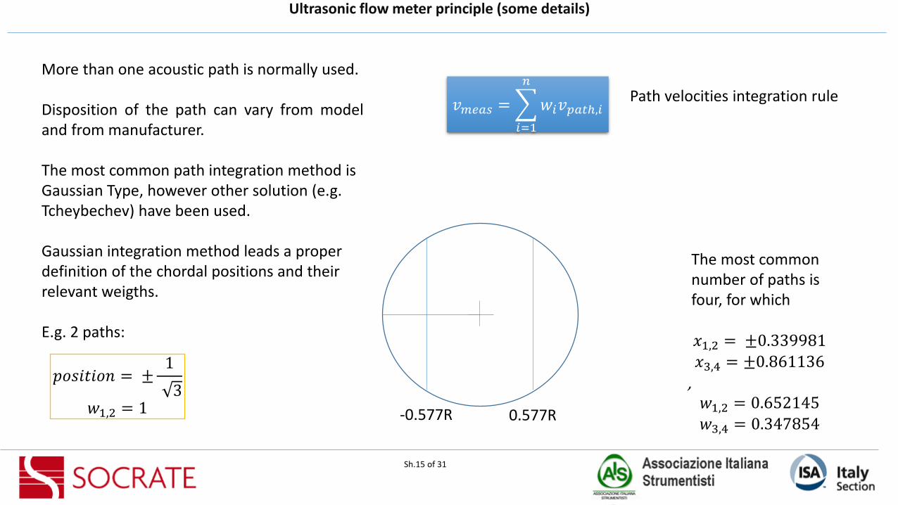
More than one acoustic path is normally used.
Disposition of the path can vary from modeland from manufacturer.
The most common path integration method isGaussian Type, however other solution (e.g. Tcheybechev) have been used.
Gaussian integration method leads a properdefinition of the chordal positions and theirrelevant weigths.
E.g. 2 paths:
𝑣𝑚𝑒𝑎𝑠 =
𝑖=1
𝑛
𝑤𝑖𝑣𝑝𝑎𝑡ℎ,𝑖
𝑝𝑜𝑠𝑖𝑡𝑖𝑜𝑛 = ±1
3𝑤1,2 = 1 0.577R-0.577R
The most common number of paths isfour, for which
𝑥1,2 = ±0.339981
𝑥3,4 = ±0.861136
, 𝑤1,2 = 0.652145
𝑤3,4 = 0.347854
Path velocities integration rule

Ultrasonic flow meter principle – velocity profile
Sh.16 of 31
Velocity profile may alter the ultrasonic waves flight times, ultimately themeasurement accuracy.
a
xh
ℎ2 + 𝑥2
∆𝑡 =2𝑐𝑜𝑡𝜃
𝑐2න− 𝑎2−ℎ2
+ 𝑎2−ℎ2
𝑉 ℎ2 + 𝑥2 𝑑𝑥
Methane in a ID=730mm pipeVm=5 m/s,P=70 bar
𝑉 𝑟 =1 + 2𝑛 1 + 𝑛
2𝑛2𝑉𝑚(1 −
𝑟
𝑎)1𝑛
𝑉 𝑟 = 2𝑉𝑚[1 − (𝑟
𝑎)2]
Turbulent flow (n=6)
Laminar flow
0
2
4
6
8
10
12
0 100 200 300 400
velic
ty /
m/s
)
pipe radius
velocity profiles
laminar turbulent
𝑐2 =𝛾𝑃
𝜌
This simple mathematical model was tested with two velocity profiles:
Speed of sound
0.00E+00
1.00E-05
2.00E-05
3.00E-05
4.00E-05
5.00E-05
6.00E-05
0 R/3 0.577R
Transit time difference
Laminar Turbulent
19%
12%-5%
Ultrasonic flow meter principle – uncertaintycontribution due to measurement and calculations
Sh.17 of 31
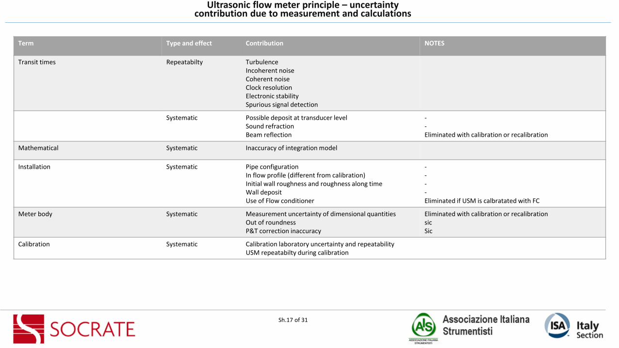
Term Type and effect Contribution NOTES
Transit times Repeatabilty TurbulenceIncoherent noiseCoherent noiseClock resolutionElectronic stabilitySpurious signal detection
Systematic Possible deposit at transducer levelSound refractionBeam reflection
--Eliminated with calibration or recalibration
Mathematical Systematic Inaccuracy of integration model
Installation Systematic Pipe configurationIn flow profile (different from calibration)Initial wall roughness and roughness along timeWall depositUse of Flow conditioner
----Eliminated if USM is calbratated with FC
Meter body Systematic Measurement uncertainty of dimensional quantitiesOut of roundnessP&T correction inaccuracy
Eliminated with calibration or recalibrationsicSic
Calibration Systematic Calibration laboratory uncertainty and repeatabilityUSM repeatabilty during calibration

Ultrasonic flow meter principle – uncertaintycontribution due to calculation of gas parameter
Sh.18 of 31
Term Type and effect Contribution notes
Density Systematic Uncertainity and repeatability of the densitometerDensity temperature\pressure correction (calibration and inline)
Compressibility Systematic EOS model uncertaintyGC (or other analysis) uncertainty
Pressure Systematic Trasnmitter uncertaintyStability of the instrumentRFI effects on instrumentEnivormnetal condtions (P,T)MountingVibration
Temperature Systematic Trasnmitter\element uncertaintyStability of the instrumentRFI effects on instrumentEnivormnetal condtions (P,T)MountingVibration
Flow computer Systematic CalculationsSignal acquisition loop

Ultrasonic flow meter principle – uncertainty model
Sh.19 of 31
Uncertainty of the measurement, simplified model
(𝑢𝑐 𝑞
𝑞)2= 𝑢𝑐𝑎𝑙
2 + 𝑢𝑜𝑝2 + 𝑢𝑐𝑜𝑚
2 + 𝑢𝑓𝑐2
(𝑢𝑐 𝑞𝑠
𝑞𝑠)2= 𝑢𝑐
2 + 𝑢𝑝2+ 𝑢𝑡
2+ 𝑢𝑧/𝑧02
(𝑢𝑐 𝐸
𝐸)2= 𝑢𝑞𝑠
2 + 𝑢𝐻𝑠2
Uncertainty of the inline volumetric flow rate
Uncertainty of the standard volumetric flow rate
Uncertainty of the energy flow rate
ucal : standard uncertainty of the meter after calibrationuop: standard uncertainty of the meter in operationucom: standard uncertainty of the signal transmissionufc : standard uncertainti of the flow computer acquisition and AD conversionuP : standad uncertainty of the pressure measurmentuT : standard uncertaintiy of the temperature measurementuZ/Z0: standard uncertainity of the compressibility factor calculation (EOS and analysis)uHS : standard uncertainty of the calorific value calculation or analysis

Ultrasonic flow meter principle – uncertainty
Sh.20 of 31
0
200000
400000
600000
800000
1000000
1200000
1400000
0 5 10 15
0.559
0.559
0.560
0.560
0.561
0.561
0.562
0.562
0.563
0.563
0.564
0.564
VO
L. F
LOW
RA
TE A
T ST
AN
D. C
ON
D.
[SM
³/H
]
AXIAL FLOW VELOCITY [M/S]
Relative Expanded Uncertainty Vol. flow rate at stand. cond.
OVERALL EXPANDED UNCERTAINTY
USM CALIBRATION RESULT (after correction)
Measurand U%(95%)
USM (calibration) 0.21 – 0.20
Pressure 0.16
Temperature 0.0487
Compressibility factor(model and analysis)
0.34
Installation effects 0.16
Typical uncertainty (U) for an ultrasonic meterrun is 0.5 – 0.7 %
Revamping a metering system– case study
Sh.21 of 31
4. Case study

Sh.22 of 31
BAUMGARTEN SITEOperators: EUSTREAM, TAG
6 x 30” LEFM 380Ci installed in parallel at the BAUMGARTEN Border Station in Austria replacing existing Orifice Stations
BAUMGARTEN receives 1/3 of Russian gas into Europe and distributes this within the Austria network and towards Northern Italy
Application challenge: Only 10 available upstream and flow conditioners were to be avoided due to pressure drop and compression costs
Cameron LEFM 380Ci is an OIML R137 Class 0.5 device with a minimum of 5D and no flow conditioner
Revamping a metering system– case study

Sh.23 of 31
Major Import Station accepting gas from Austria into Northern Italy
Operator: TAG
Onshore Austria
16 off 20” Cameron LEFM 380Ci mounted in series within an 8 stream system configuration
Picture of meters being installed and insulation added
ARNOLDSTEIN STATION
Revamping a metering system– case study

Sh.25 of 31
# Type Description
1 Measurement Pay&check UFM configurationClass 0.5 OIML
2 Measurement Class 0.5 OIML R137
3 Measurement\Environmental Data transfer via DSFG bus, typical of germanworld
4 Enviromental Maintain calibration setup in installation
5 Environment Respect the tie-in dimensions, i.e. fit overalllength of the line.
6 Environment Materials as per end user heritage
7 Environment Lead time in accordance with plant shut down
8 Environment maximize availability of the measurement
MAIN PROJECT CONSTRAINTS
Revamping a metering system– case study

Sh.25 of 31
Revamping a metering system– case study
Constraint respected:1. pay&check2. Fit the available space8. Maximize maintenability

Sh.28 of 31
Flow conditioner and calibration issues
Installing a flow conditioner at any position in the meter runupstream of the USM will cause a change of the meter’sindicated flowrate. This change depends on many factors (e.g.flow conditioner type, meter type, position relative to theUSM, flow perturbation upstream of the flow conditioner,etc…)… To avoid this additional uncertainty, the best option isthat the USM is calubrated with the actual flow conditionerand meter tube as one package (USMP)
ex ISO 17089-1
If a flow conditioner is to be used the meter should be calibrated along with its flow conditioner in the correct location and orientation.This set up should be carefully maintained in the field…
No flow conditioner used• No maintenance concerns• No additional pressures losses• Only the meter itself need be returned to
the lab for calibration
Revamping a metering system– case study

Sh.26 of 31
TRANSDUCER ARRANGMENT IN USED UFM
Revamping a metering system– case study
Constraint respected:2. OIML 0.5 Class8. Maximize measurement availabilty and maintenabilty

Sh.29 of 31
Revamping a metering system– case study
Constraint respected:3. Dsfg bus DT

Sh.30 of 31
Revamping a metering system– case study
Constraint respected:4. Maintain calibration setup in field installation

Revamping a metering system
Sh.31 of 31
?

Sh.27 of 31
Keep Internal conditions along time
Corrosion altersmeter performance!
Application of special corrosion and adhesionresistance coatings can help preserve the original condtion without alteiring itsperformance.
The coating can be applied to both the body and the transducer housing
Revamping a metering system– case study
Revamping a metering system
Sh.- of -
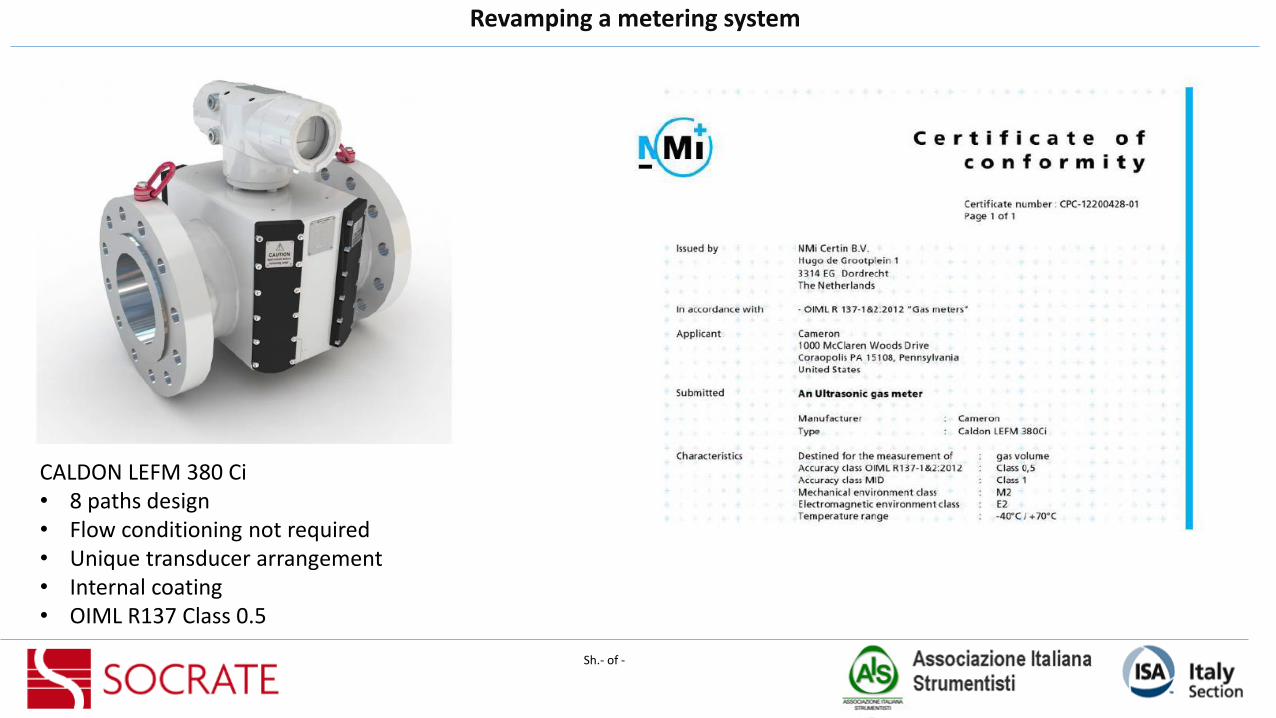
CALDON LEFM 380 Ci• 8 paths design• Flow conditioning not required• Unique transducer arrangement• Internal coating• OIML R137 Class 0.5