aj 1101*2- - connecting repositories · beba n angin ditentukan mengiku t standar bd s cp3 bab v...
TRANSCRIPT

aj 1101*2-
UNIVERSITI TUN HUSSEIN ONN MALAYSIA
PENGESAHAN STATUS TESIS •
THE STRUCTURAL BEHAVIOR OF LOW-RISE RESIDENTIAL BUILDING DUE TO WIND AND SEISMIC LOADS
Saya ANUCIANO DOMINGOS PINTO GUTERRES mengaku membenarkan tesis Sarjana ini disimpan di Perpustakaan dengan syarat-syarat kegunaan seperti berikut:
1. Tesis adalah hakmilik Universiti Tun Hussein Onn Malaysia 2. Perpustakaan dibenarkan membuat salinan untuk tujuan pengajian sahaja. 3. Perpustakaan dibenarkan membuat salinan tesis ini sebagai bahan pertukaran antara institusi
pengajian tinggi. 4. ** Sila tandakan )
SESI PENGAJIAN: 2007/2008
(Mengandungi maklumat yang berdarjah keselamatan atau • SULIT kepentingan Malaysia seperti yang termaktub di dalam AKTA MALAYSIA RASMI 1972)
(Mengandungi maklumat TERHAD yang telah ditentukan oleh organisasi/badan di mana penyelidikan dijalankan) • TIDAK TERHAD
Disahkan oleh
(TANDATANGAN PENULTS) (TANDATANGAN PENYELIA)
Alamat Tetap: Becora-Dili-Timor Leste PROF. Dr. ABDUL AZIZ B. DATO' ABDUL SAMAD
(Nama Penyelia)
TARUCH: TARKH:
CATATAN: * Potong yang tidak berkenaan. ** Jika tesis ini SULIT atau TERHAD, sila lampirkan surat daripada pihak berkuasa/organisasi berkenaan dengan menyatakan sekali sebab dan dikelaskan sebagai SULIT atau TERHAD.
• Tesis dimaksudkan sebagai tesis bagi Ijazah Doktor Falsafah dan Sarjana secara penyelidikan, atau disertai bagi pengajian secara kerja kursus dan penyelidikan atau Laporan Projek Masters.
"I hereby declare that we have read this thesis and in our opinion this thesis is
sufficient in terms of scope and quality for the award the degree of Master of Civil
Engineering "
Student :
ANUCIANO DOMINGOS PINTO GUTERRES
Date
Supervisor by
Supervisor I
PROF. DR. ABDUL AZIZ B. DATO' ABDUL SAMAD
Supervisor II
IK
ASSOC PROF. DR. KEMAS AHMAD ZAMHARI
THE STRUCTURAL BEHAVIOUR OF LOW - RISE RESIDENTIAL
BUILDING DUE TO WIND AND SEISMIC LOADS
ANUCIANO DOMINGOS PINTO GUTERRES
A thesis submitted in fulfillment of
the requirement for the award of the the
Degree of Master of Civil Engineering
Faculty of Civil and Environmental Engineering
Universiti Tun Hussein Onn Malaysia
JUNE 2008
ii
I declare that this thesis entitled "The structural behavior of low rise residential building
due to wind and seismic loads" is the result of my own research except as cited in the
refcrenccs . The thesis has not been accepted for any degree and is not concurrently
submitted in candidate of any other degree"
Signature
Author
Date
Anuciano Domingos Pinto Guterres
iii
ACKNOWLEDGEMENT
In the name of God, the most gracious, the most merciful
With the highest praise to God that I manage to complete this studies
successfully. The completion of this study has been made possible by the assistance of
many people. I would like to extend my sincere gratitude to my supervisor Prof. Dr.
Abdul Aziz B. Dato' Abdul Samad for his assistance and inspiration towards the
progress of this study. Throughout the year, my supervisor has been patiently monitoring
my progress and guided me in right direction and offering encouragement. I would also
like to thank Assoc. Prof. Dr. Kemas Ahmad Zamhari for his help and valuable
suggestions. My thanks to Pn. Noridah Bt. Mohamad and Pn. Tuan Norhayati Bt. Tuan
Chik for their great help in giving me new insights into different aspects of the issues
involved in this study.
My highest gratitude to the Malaysia Government for providing me with the
scholarship to study in Universiti Tun Hussein Onn Malaysia. I also want to thank all the
staff of center graduation of the Universiti Tun Hussein Onn Malaysia (UTHM) for their
great help and for their sincere cooperation during this study. I would also like to thank
all staff of Dili Institute of Technology (DIT) for their interest and encouragement. I
wish to thank my family Agostinha De Oliveira, Febynola, Vivano, Junelson, brother,
and my parent's steady support and encouragement. They have been a constant source of
motivation for my work.
iv
ABSTRAK
Angin dan seismic adalah ancaman semulajadi yang membawa kepada
kemusnahan atau keruntuhan bangunan-bangunan rendah.. Kajian ini menerangkan
kesan angin dan seismic kepada sifat penstrukturan bangunan-bangunan rendah dalam
membangunkan reka bentuk bangunan kediaman dengan mengambil kira tahap ekonomi
negara serta bahan-bahan tulen sedia ada. Perolehan data telah dibuat di suatu kawasan
angin dan seismic bertekanan tinggi selama 20 tahun pusingan di Timor Leste. Kajian
ini memfokus kepada analisis dua-dimensi rangka penahanan 3-petak 4-tingkat dalam
kaedah lakaran reka bentuk. Beban angin ditentukan mengikut standard BS CP3 bab V
bahagian 2 1972. Bebanan seismic pada bangunan diperolehi pada PGA rendah,
sederhana dan tinggi selari dengan UBC 1997. Analisis ini dijalankan menggunakan
perisian STAAD Pro 2004 untuk mengenal pasti elemen-elemen kritikal pada bangunan-
bangunan berskala rendah di bawah riceh, anjakan dan moment berdasarkan bebanan
angin dan seismic. Pengaplikasian beban angin dan seismic daripada bahagian tepi dan
hadapan bangunan memberi pelbagai kesan kepada anjakan, riceh dan moment kepada
struktur bangunan. Dengan memberi kepelbagaian sistem pengukuhan V dan X kepada
struktur, pengurangan anjakan dengan riceh terendah dan nilai moment untuk komponen
bangunan dapat dicapai. Hasil kajian menunjukkan struktur dengan sistem pengukuhan
sesuai memperlihat pengurangan sebanyak 70% anjakan , 50% moment dan 33.5% riceh.
Keadaan ini menerangkan bahawa sistem pengukuhan yang dicadangkan adalah kaedah
yang efektif dalam meningkatkan kekukuhan dan kestabilan stuktur bangunan
seterusnya mengurangkan kemungkinan berlaku keruntuhan bangunan.
Keywords:Bangunan rendah, STAAD Pro, Angin dan Seismic, sistem pengukuhan.
XIX
ABSTRACT
Buildings are subjected to natural hazards such as wind and seismic, and when
subjected too, will have an effect on the overall behaviour of the structure. This study
describes the effect of wind and seismic loads towards the structural behaviour of low
rise residential building in Timur Leste. Various bracing system design were proposed to
the building and analytical results were recorded and observed. Wind data velocity (V)
was taken at 33 m/s in open country. The data was collected at location for wind and
seismic on high intensities for a 20 year cycle. For the simplicity of illustrating the
design, the study focuses on the analysis of a two and three dimensional three bay four-
storey moment resisting frames on rigid foundation. Lateral wind load was determined
in accordance to BS CP3 Chapter V part 2 1972 standard. Seismic deign load on
building was obtained at Peak Ground Acceleration (PGA) for low, medium and high
ground motion on building in accordance with UBS 1997. The analysis of the building
was conducted using STAAD Pro 2004 to identify critical members and elements of the
low rise building under shear, displacement and moments due to wind and seismic
loading. In applying wind and seismic load from side and front of building, large values
of displacement, shear and moment was observed at critical points of the structure. By
providing bracing system types V and X to the structure, less displacement with lower
shear and moment values for the building component was achieved. Result shows that
for structures with suitable bracing system, an overall reduction of about 70% in
displacement; 50% in moment and 33.5% in shear was observed. This implies that by
applying the bracing system, the rigidity and stability of the structure has increased and
the risk of collapse has substantially reduced.
Keywords: Low rise building, STAAD Pro, wind and seismic load, bracing system.

TABLE OF CONTENT
CHAPTER CONTENT PAGE
ACNOWLEDGEMENT iii
ABSTRACT iv
TABLE OF CONTENT vi
APPENDICES x
SYMBOLS xi
FIGURE xiv
TABLE xxiii
INTRODUCTION
1.1 Introduction
1.2 Statement of problem
1.3 Objective
1.4 Scope of study
1.5 Significant of study 5
4
4
3
II LITERATURE REVIEW 6
2.1 Introduction 6
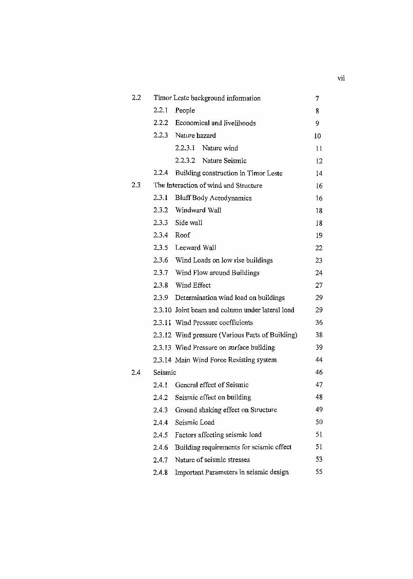
Vll
2.2
2.3
2.4
Timor Leste background information 7 2.2.1 People 8 2.2.2 Economical and livelihoods 9 2.2.3 Nature hazard 10
2.2.3.1 Nature wind 11
2.2.3.2 Nature Seismic 12 2.2.4 Building construction in Timor Leste 14 The Interaction of wind and Structure 16 2.3.1 Bluff Body Aerodynamics 16 2.3.2 Windward Wall 18
2.3.3 Side wall 18
2.3.4 Roof 19
2.3.5 Leeward Wall 22
2.3.6 Wind Loads on low rise buildings 23
2.3.7 Wind Flow around Buildings 24
2.3.8 Wind Effect 27
2.3.9 Determination wind load on buildings 29
2.3.10 Joint beam and column under lateral load 29
2.3.11 Wind Pressure coefficients 36
2.3.12 Wind pressure (Various Parts of Building) 38
2.3.13 Wind Pressure on surface building 39
2.3.14 Main Wind Force Resisting system 44
Seismic 46
2.4.1 General effect of Seismic 47
2.4.2 Seismic effect on building 48
2.4.3 Ground shaking effect on Structure 49
2.4.4 Seismic Load 50
2.4.5 Factors affecting seismic load 51
2.4.6 Building requirements for seismic effect 51
2.4.7 Nature of seismic stresses 53
2.4.8 Important Parameters in seismic design 55
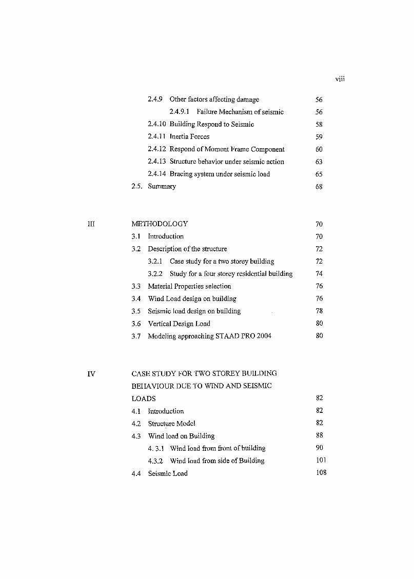
vm
2.4.9 Other factors affecting damage 56
2.4.9.1 Failure Mechanism of seismic 56
2.4.10 Building Respond to Seismic 58
2.4.11 Inertia Forces 59
2.4.12 Respond of Moment Frame Component 60
2.4.13 Structure behavior under seismic action 63
2.4.14 Bracing system under seismic load 65
2.5. Summary 68
in METHODOLOGY 70
3.1 Introduction 70
3.2 Description of the structure 72
3.2.1 Case study for a two storey building 72
3.2.2 Study for a four storey residential building 74
3.3 Material Properties selection 76
3.4 Wind Load design on building 76
3.5 Seismic load design on building 78
3.6 Vertical Design Load 80
3.7 Modeling approaching STAAD PRO 2004 80
IV CASE STUDY FOR TWO STOREY BUILDING
BEHAVIOUR DUE TO WIND AND SEISMIC
LOADS 82
4.1 Introduction 82
4.2 Structure Model 82
4.3 Wind load on Building 88
4.3.1 Wind load from front of building 90
4.3.2 Wind load from side of Building 101
4.4 Seismic Load 108
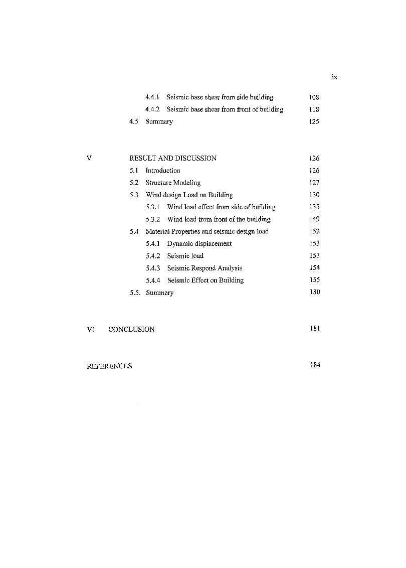
ix
4.4.1 Seismic base shear from side building 108
4.4.2 Seismic base shear from front of building 118
4.5 Summary 125
V RESULT AND DISCUSSION 126
5.1 Introduction 126
5.2 Structure Modeling 127
5.3 Wind design Load on Building 130
5.3.1 Wind load effect from side of building 135
5.3.2 Wind load from front of the building 149
5.4 Material Properties and seismic design load 152
5.4.1 Dynamic displacement 153
5.4.2 Seismic load 153
5.4.3 Seismic Respond Analysis 154
5.4.4 Seismic Effect on Building 155
5.5. Summary 180
VI CONCLUSION 181
REFERENCES 184
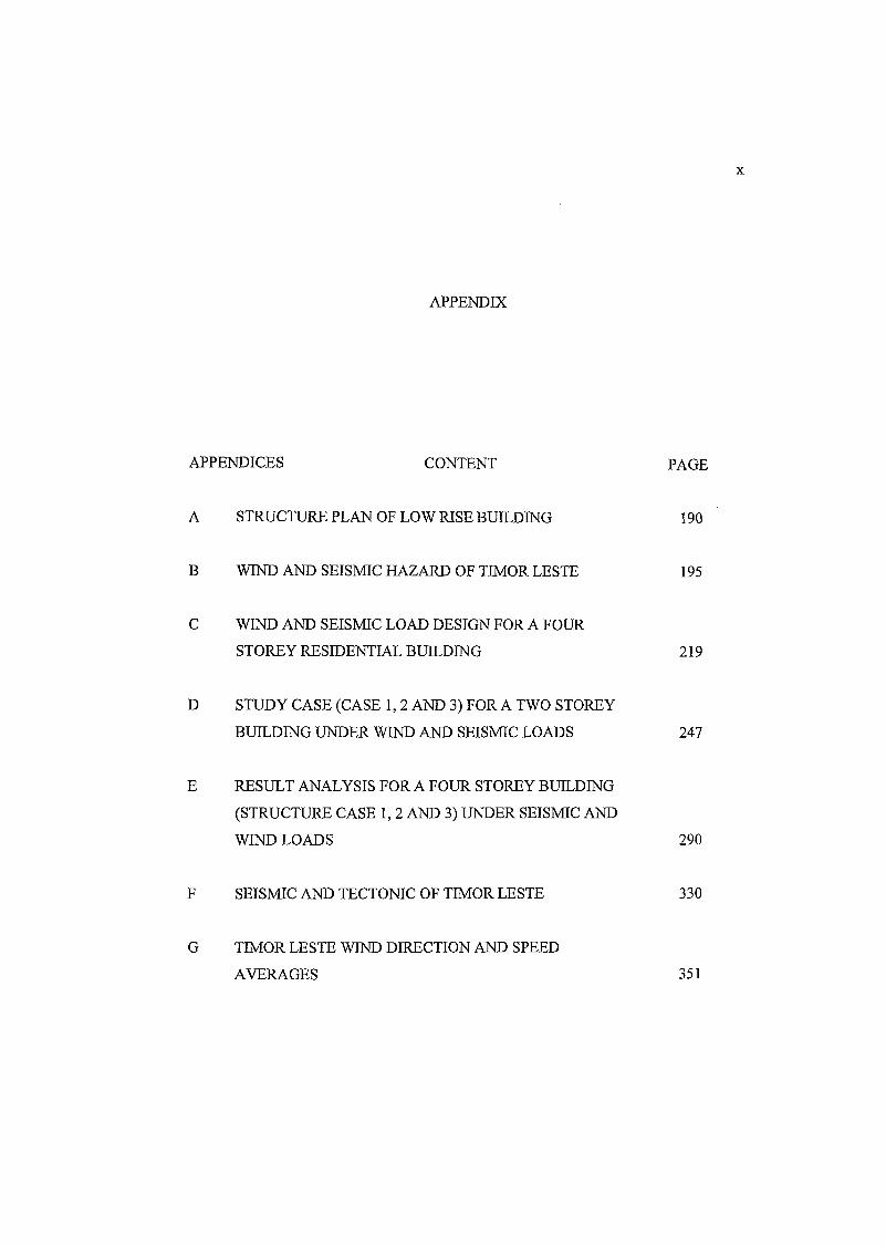
APPENDIX
APPENDICES CONTENT PAGE
A STRUCTURE PLAN OF LOW RISE BUILDING 190
B WIND AND SEISMIC HAZARD OF TIMOR LESTE 195
C WIND AND SEISMIC LOAD DESIGN FOR A FOUR
STOREY RESIDENTIAL BUILDING 219
D STUDY CASE (CASE 1, 2 AND 3) FOR A TWO STOREY
BUILDING UNDER WIND AND SEISMIC LOADS 247
E RESULT ANALYSIS FOR A FOUR STOREY BUILDING
(STRUCTURE CASE 1, 2 AND 3) UNDER SEISMIC AND
WIND LOADS 290
F SEISMIC AND TECTONIC OF TIMOR LESTE 330
G TIMOR LESTE WIND DIRECTION AND SPEED
AVERAGES 351
SYMBOL
a - Times the acceleration
A^ Effective frontal (strip) area considered for the structure at height z
B - Width of building normal to the oncoming wind
C - Drag force coefficient; and
C - General Factor that accounts for the specific
Ce - Combined height, exposure and gust factor coefficient
Cf - Force coefficient for the building
Cp - Pressure coefficient
Cq - Pressure coefficient for the structure under consideration
Cdyn - Dynamic response factor (total load/ mean load)
d0 - The lowest height of validity of U(z)m m
DL - Dead Load
E - Modulus elasticity
EL - Seismic Load
/ 0 - First mode natural frequency of vibration of a structure in the along
wind direction in hertz.
fc - 2Q sin <f> = Coriolis parameter in 1/s
F̂ - Along-wind equivalent static load on the structure at any height z
corresponding to strip area A
gR - Peak factor for resonant response (1 hour period)
ht - Height of the i floor above the base
x i i
hk - Denotes the internal boundary layer
H - Average roof height of structure above the ground
H - The height to caves is parapet
Hs - Height factor for the resonant response
I An importance factor
Ih - Turbulence Intensity, Obtain from table 31 by setting z equal to h
k - The power that differs from one seismic code to another
K - Von Karman's constant k = 0.4
L - The greater horizontal dimension of a building
LL - Live Load
M - Moment
M - Mass of the building
N - Number of stories
P - Wind pressure
P - Mean wind load
P0 - Atmospheric pressure
Pz - Wind pressure in N/m2 at height z (pz) obtained 0.6 (N/m2)
P(z,t) - Peak externally applied wind load in which
jPmax - 1 sec. Maximum pressure
P ^ - 1 sec. Minimum pressure
q - Dynamic pressure of wind (stagnation pressure)
Qs - Wind stagnation pressure
Rw - Principal new factor
S - Size reduction factor given
Sa . Altitude and topography factor
Sb . Terrain and building factor
Sd . A direction factor used to ensure that when specific wind direction are
used in the design calculations the risk of accidences is the same for
direction.
xiii
Sp . Probability factor to allow the designer to select a risk other than the
standard 2% per annum.
Ss . A seasonal factor to allow for non-permanent structures
51 . Topography factor
52 . Factor accounting for building height, element size and terrain category
53 . Probability factor used to vary the annual design risk. (Analysis S3=1.0)
54 . Direction factor defined as for BS 6399. In this analysis S4= 1.0
U(z) - Mean velocity of the wind at height z above ground in m/s
V - Mean wind velocity at building heigt
V - Seismic base shear (Vertical component of force)
Vs - A site wind speed
x - Distance from the step in roughness
W - The lesser horizontal dimension a building
WL - Wind Load
W - Weigh of building
W{ - The weight of building
z - Height above ground in m
Z - Factor adjust for probability
z0 - Roughness length in meter
Z0 max - The larger of the upstream and down stream roughness
Q - 0.726 10-4 = angular rotation velocity in rad/s
(f> - Latitude of location in degree
p - Density by of air (1.225 kg/m3)
l /2pF2 - Dynamic pressure-Static pressure at building height
xiv
FIGURE
NO CONTENT PAGE
2.1. Locality map of east Timor Leste 7
2.2 Map of Districts in Timor Leste 9
2.3 (a) Prevailing wind Season in Timor Leste, (b) Global
Wind Map 11
2.4 Seismic epicenters in the Banda Sea region 12
2.5 Peak Ground acceleration of Timor Leste due to seismic
2005 13
2.6 (a) A traditional Fataluku house from Lospalos in east
Timor Leste, (b) One of the styles of Uma Lulik (traditional
houses) in the Atsabe sub district (west Timor Leste) 15
2.7 (a) Many houses in villages are still use bamboo and wood
building, (b) a traditional single storey building use
reinforce concrete, (c) Two storey building (office) in the
center of Dili Timor Leste, (d) Two storey building (flat) is
made of reinforce concrete 15
2.8 (a) Parameter of wind, (b) Typical wind flow patterns
around the building 17
2.9 a) Windward and leeward pressure, b) Roof and side wall
pressure 18
2.10 The conical vortices 20
2.11 Models building 21
XIX
2.12 (a) Building configurations showing frames attached to
7.5m high walls, (b) Roof and wall pressure zone for
components and cladding 23
2.13 (a).Wind flow lines around a simple building shape, (b) and
wind pressure diagram on gabled roof building 25
2.14 (a) and (b)Basic fluid mechanics govern how wind
pressures Influence structures, (c) Distribution of pressures
(+) and suctions (-) on house with a low-sloped roof with
wind perpendicular to eave 26
2.15 Wind flow around Building 27
2.16 Wind load on external walls, pitched and hipped 28
2.17 Representation of building loaded by wind. The load on
amp concentration in the node 31
2.18 Structure of wind velocity and pressure on building 34
2.19 Variation of internal pressure with exterior building 36
2.20 Notation for heights Along-wind load on a structure on a
strip area at any height. 43
2.21 Common terms and factors affecting shaking intensity 47
2.22 Fundamental seismic response of building 49
2.23 Seismic vibrations of a building and resultant seismic force 50
2.24 Stress condition in a wall element 54
2.25 Lay out of eight storey building 55
2.26 (a) Failure mechanism of wall enclosure without roof, (b)
Long building with roof trusses Failure mechanism of wall
enclosure without roof 57
2.27 Deformation of the shear wall with openings 58
2.28 Importance of designing walls or column for horizontal
seismic force of the pacific seismic engineering research 60
2.29 Seismic Effect on view of front face building 61
2.30 Damage to a no ductile reinforced concrete beam 61
2.31 Failure of lap splices in a moment frame connection 62
xvi
2.32 Typical Transverse reinforcement in column 62
2.33 Damage to moment frame columns 63
2.34 Horizontal shear in corner joint 65
2.35 Various types of eccentrically braced, (a) V is bracing; (b)
K bracing; (c) X is bracing and (d) Y bracing 66
2.36 Eccentric beam-column connections in an exterior frame 68
3.1 Flow chart of building analysis 71
3.2 2D Frame Analysis for Case 2a and Case 2b (Front View) 73
3.3 2D Frame Analysis for Case 2a and Case 2b (Side View) 73
3.4 Plane view of a two storey Building 74
3.5 Side view a four storey Building 75
3.6 Front view four storey building labeling 75
3.7 Flow chart for wind load design 77
3.8 Flow chart for seismic load design 80
3.9 Flow chart for STAAD Pro 2004 81
4.1 Structure plan of a two storey building due to lateral
pressure 83
4.2a Frame 1 structure under loading 84
4.2b Frame 2 structures under loading 85
4.3 Frame 1 with various bracing system 86
4.4 Frame 2 with various bracing system 87
4.5a Illustration of wind pressure from front of building (3D) 88
4.5b Illustration Wind pressure from side of building (3D) 89
4.6 Vertical and Lateral Load (DL + LL + WL) for Frame 2a
(2D) 89
4.7 Illustration of displacement, shear and moment under Wind
load (3D) 90
4.8 2D Bending moment under wind load (WL) only for Frame
2a (Case 1) 91
4.9 2D bending moment under combination load for Frame 2a
(Case 1) 92
xvii
4.10 Comparison maximum moment under combination load on
structure Frame 2 a (Case 1, Case 3, Case 5 and Case 6) 94
4.11 Shear force under combination loading for structure Frame
2a (Case 1) 95
4.12 Maximum shear force on joint beams under load for
structure Frame 2a (Case 1 with no bracing) 95
4.13 Comparison on the structure Case 1, Case 2 and case 5
under shear 98
4.14 2D Joint Displacement for structure Frame 2a (Case 1)
under Dead Load and Live Load (DL+LL) 98
4.15 Maximum joint displacement on Frame 2a Case 1 to Case 6 99
4.16 Maximum joint displacement under gravity load (DL+LL) 100
4.17 Maximum joint displacement under Wind Load (WL) only 100
4.18 Bending moment under gravity load 101
4.19 Shear force under gravity load 102
4.20 Shear bending under wind load 103
4.21 Shear force on Element building under wind load 103
4.22 Bending moment under combination load 104
4.23 Shear force under combination load Frame 1 (Case 1) 104
4.24 Joint displacement under combination load on Frame la
(Case 1) 105
4.25 Maximum section Beams displacement under gravity load
Frame 1 (Case 1 to Case 6) 105
4.26 Joint displacement under wind load Frame la (Case 1 to
Case 6) 106
4.27a Displacement under combination load Frame la (Case 1 to
Case 6) 106
4.27b Joint displacement under combination load (Frame la) 107
4.28 Structure under seismic base shear 108
4.29 Gravity Load and Seismic base shear of Frame 1 (2D) 109
XV1U
4.30 Joint beams occurred rotate (vibrate) and shear forces and
displacement under seismic load from side of building (3D) 110
4.31 Bending moment due to Seismic load 111
4.32 Seismic force and rotational moment on joint building 112
4.33 Seismic shear force on structure Case 1 under axial load
(Frame la) 113
4.34 Bending moment under combination load (DL+LL+EL)
Frame 1 114
4.35 Shear force under combination load 114
4.36 Illustration of joint displacement (2D) 115
4.37 Joint displacement due to seismic load 115
4.38 Joint displacement under gravity load for Frame la (Case 1
to Case 6) 116
4.39 Joint displacement under seismic load for Frame la (Case 1
to Case 6) 117
4.40 Joint displacement under combination load Frame la(Case
1 to Case 6) 117
4.41 a Plane for a two storey building (Frame 2) 118
4.41b Seismic effect on building (3D) 119
4.42 2D Bending Moment under Seismic Load (Frame 2a) 120
4.43 2D Shear Force (shear Y) under Seismic Load (Frame 2a) 120
4.44 2D Bending Moment under Combination Load
(DL+LL+EL) Frame 2a 121
4.45 Structure Shear under Combination Load (Frame 2a) 121
4.46 An illustration of joint displacement under Seismic Load
(EL) from front of Frame 2a (Case 1) 122
4.47 Joint displacement under Gravity Load (DL+LL) 123
4.48 Joint displacement under Seismic Load (EL) 123
4.49 Joint displacement under Combination load (DL+LL+EL) 124
4.50 Section beam displacement under Seismic load 125
5.1 Structure Case 1 (Structure front 2D) 127
XIX
5.2 V bracing system for Structure Case 2 (Structure front 2D) 128
5.3 X bracing system for structure Case 3 (Structure front 2D) 128
5.4 Structure Case 1 (Structure side 2D) 129
5.5 V bracing system for structure Case 2 (Structure side 2D) 129
5.6 X bracing system for structure Case 3 (Structure side 2D) 129
5.7 Uniforms wind load on building 131
5.8 Concentrate wind load and gravity load 131
5.9 Illustration wind pressure from side building in 3D 132
5.10 Uniform wind load from front of building 133
5.11 Concentrate wind load from front of Building 133
5.12 Illustration of wind pressure from front of Building in 3D 134
5.13 Bending moment under gravity load 136
5.14 Joint displacement under gravity load 137
5.15 Shear under wind load (Case 1) 139
5.16 Joint displacement under wind load structure Case 1 140
5.17a Joint displacement under combination load 141
5.71b Illustration structure Case 1, Case 2 and Case 3 and joint
displacement under wind load (2D) 142
5.17c Structure Case 1, Case 2 and Case 3 (2D) 142
5.18 Comparison Joint Displacement due to wind load on
structure Case 1, Case 2 and Case 3 144
5.19 Comparison joint displacement under wind load 145
5.20 Comparison joint displacement under gravity load 145
5.21 Comparison joint displacement under combination load 146
5.22 Comparison joint displacement under gravity and wind
load (wind pressure front) 147
5.23 Joint displacement under combination load on building 147
5.24 Section beam displacement under combination load 148
5.25 Vertical Beam (column) displacement under combination
load 148
5.26 Column Displacement subjected to either gravity 149
XIX
5.27 Joint displacement under combination load (wind load from
front of building) 149
5.28 Comparison Section displacements under gravity and wind
load 150
5.29 Maximum section beams displacement under combination
load 150
5.30 Comparison a maximum displacement on joint beam due to
wind load from front and side of building 151
5.31 Seismic distribution load from side of building 153
5.32 Seismic concentrate load from side of building 154
5.33 Seismic ground motion and distribution force view from
plan building 156
5.34a Illustration seismic base shear and distribution load on
building 158
5.34b Illustration seismic distribution load ob building used
STAAD Pro 158
5.35 Joint connection displacement under seismic load (low load
from side of building) 159
5.36 Joint beam no. 1039 displacement due to low, medium and
high seismic load for structure Case 1, Case 2 and Case 3 160
5.37 Maximum section beam displacement for beam no. 1928
under seismic load 161
5.38 Shear Force under seismic low Load on structure unbraced
structure (Case 1) 162
5.39 Maximum Shear Force on element building (beams) 163
5.40 Maximum shear force on element columns 163
5.41 Bending moment under seismic low load for structure Case
1 164
5.42 Maximum Moment for beam no 1133 under combination
load 165