a.j. antunes vizion chill ice heat exchanger ice series … · waste water from the ice machine...
TRANSCRIPT
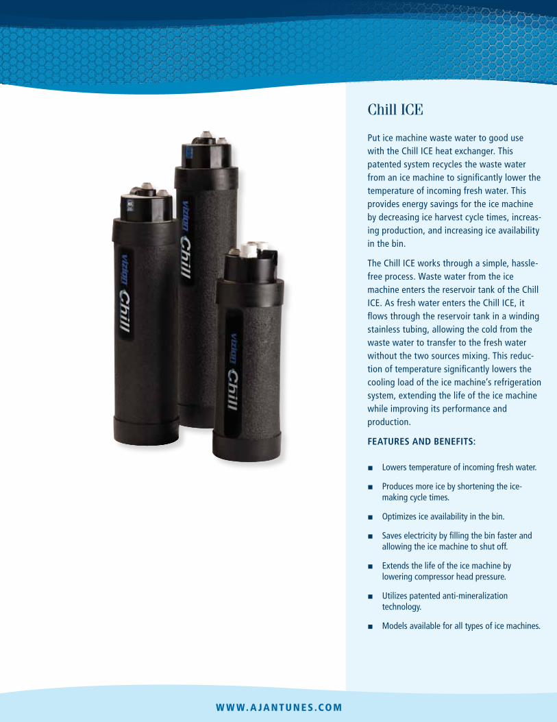
Chill ICE
Put ice machine waste water to good use with the Chill ICE heat exchanger. This patented system recycles the waste water from an ice machine to significantly lower the temperature of incoming fresh water. This provides energy savings for the ice machine by decreasing ice harvest cycle times, increasing production, and increasing ice availability in the bin.
The Chill ICE works through a simple, hassle-free process. Waste water from the ice machine enters the reservoir tank of the Chill ICE. As fresh water enters the Chill ICE, it flows through the reservoir tank in a winding stainless tubing, allowing the cold from the waste water to transfer to the fresh water without the two sources mixing. This reduction of temperature significantly lowers the cooling load of the ice machine’s refrigeration system, extending the life of the ice machine while improving its performance and production.
Features and beneFits:
■ Lowers temperature of incoming fresh water.
■ Produces more ice by shortening the ice-making cycle times.
■ Optimizes ice availability in the bin.
■ Saves electricity by filling the bin faster and allowing the ice machine to shut off.
■ Extends the life of the ice machine by lowering compressor head pressure.
■ Utilizes patented anti-mineralization technology.
■ Models available for all types of ice machines.
w w w. a ja n t u n es .co m

Chill ICE dimensions
Model & Mfg. no.
Width depth Height Weight
applications ICE-1000 Ice machines up to 1000 lbs.
ICE-1800 Ice machines more than 1000 lbs. ICE-1000 5.5” 5.5” 27” 7 lbs. 9700920 (14 cm) (14 cm) (58 cm) (3.1 kg)
ICE-1800 5.5” 5.5” 31” 9 lbs. 9700921 (14 cm) (14 cm) (79 cm) (4 kg)
ICE-H 7.75” 7.75” 21” 8 lbs. 9700922 (20 cm) (20 cm) (53 cm) (3.6 kg)
ICE-S 5.5” 5.5” 18” 6 lbs. 9700923 (14 cm) (14 cm) (46 cm) (2.7 kg)
ICE-1000 29” 7” 7” 6 lbs. 9700920 (74 cm) (18 cm) (18 cm) (2.7 kg)
ICE-1800 23” 9” 9” 6 lbs. 9700921 (58 cm) (23 cm) (23 cm) (2.7 kg)
ICE-H 23” 9” 9” 9 lbs. 9700922 (58 cm) (23 cm) (23 cm) (4 kg)
ICE-S 20” 7” 7” 5 lbs. 9700923 (51 cm) (18 cm) (18 cm) (2.3 kg)
Connections
Inlet Water Connections
ICE-1000 ICE-1800
ICE-S 3/8” tube fittings
ICE-H 1/2” tube fittings
Drain Water Connections
ICE-1000 ICE-1800
ICE-H ICE-S
3/4” PVC fittings
specifications
Maximum Operating Pressure 150 psi (10.5 kgf/cm2)
Minimum Operating Pressure 30 psi (2.1 kgf/cm2)
Hoshizaki North American cube ice machines only
All flake or shaved ice machines.
example installation
ICE BIN
ICE MACHINE
Ice making water drain to Chill
Ice machine
drain
Ice making water inlet to
Chill
Water service valve
Vent pipe
Floor drain NOTE: Chill ICE-S must
be installed horizontally. Bin drain
Ice making water inlet to ice machine
How it Works
1
4
3
7
7
4
5
6
2
2
3
1
5
6
Cold waste water from the ice machine enters the counter flow tube of the Chill system.
Waste water continues to the reservoir of the Chill system.
As more cold waste water enters the reservoir, it pushes the warm waste water to the drain.
Fresh water enters the stainless tubing of the Chill system.
As the water flows through the tubing, it’s chilled by the surrounding waste water in the reservoir.
Fresh water flows up the counter flow tube, where it’s chilled further by the coldest waste water entering the reservoir.
Chilled, fresh water enters the ice machine, where it’s easily converted to ice.
ICE-H
ICE-S
shipping dimensions Model & Mfg. no.
Length Width Height Weight
A.J. Antunes & Co. Headquarters/Manufacturing
180 K ehoe Boulevard Carol Stream, Illinois 60188 U S A
P h o n e ( 6 3 0 ) 7 8 4 - 1 0 0 0 T o l l F r e e ( 8 0 0 ) 2 5 3 - 2 9 9 1
F a x : ( 6 3 0 ) 7 8 4 - 1 6 5 0
Antunes Equipment Manufacturing (Suzhou) Ltd., 9 Hou Ju R oad, Building #24,
S&T P ark, SND Suzhou, Jiangsu, China 215011
Phone: 86-512-6841-3637 F ax: 86-512-6841-3907
www .ajantunes.com
P/N 1020365 Rev. C 08/10
Se e W h at B e t te r Wate r C a n Do.
A. J. ANTUNES & CO. 180 Kehoe Blvd., Carol Stream, Illinois 60188
Chill iCE-1000 (P/N 9700920), iCE-1800 (P/N 9700921), iCE-h (P/N 9700922) iNSTAllATiON iNSTrUCTiONS
SUGGESTED MATERIALS AND EQUIPMENT NEEDED: • (10 ft.) 3/4” PVC Pipe • (5) 3/4” PVC Elbow Fitting • (1) 3/4” PVC Tee Fitting • (10 ft.) Copper Tubing
ICE-1000, ICE-1800: 3/8” OD ICE-H: 1/2” OD
• (2) Brass Tubing Unions ICE-1000, ICE-1800: 3/8” OD ICE-H: 1/2” OD
• Multipurpose glue for ABS, PVC, and CPVC • Tubing Cutter • PVC Pipe Cutter • Screwdriver or Drill with Bits • Channel-Lock Pliers • Adjustable Wrench • Measuring Tape
General If you experience any problems with these instructions, contact the Technical Service Department at 630-784-1000 or toll free in the U.S. at 877-392-7854.
Warranty information All ICE-1000, ICE-1800, and ICE-H units will be free from defects in materials and workmanship for a period of five years.
Connections FrESh WATEr CONNECTiONS
Chill ICE units use Super Speedfit® tubing fittings for fresh water line connections that require no tools. Tubing (copper or plastic) is simply inserted into the fitting collet to create a secure connection.
The tubing should be inserted approximately 3/4” (1.91 cm) until it bottoms completely in the fitting to ensure there will be no leaks. The tubing end to be inserted should be straight and have a clean round cut. If the tubing is out-of-round, then carefully make a new cut before inserting into the fitting.
SUmP WATEr CONNECTiONS
Chill ICE units require the use of 3/4” (1.91 cm) PVC pipe for the sump water connections. It is important to glue all connections with the multipurpose glue. Follow the specific installation procedures to make certain there will not be a vacuum block or any reduction in water flow to the floor drain.
installation To ensure material compatibility, a multipurpose glue for ABS, PVC, and CPVC must be used. This will ensure a proper bond between the 3/4” PVC and the black ABS Sump Water Discharge Inlet.
1. Turn off the ice machine and water supply valve.
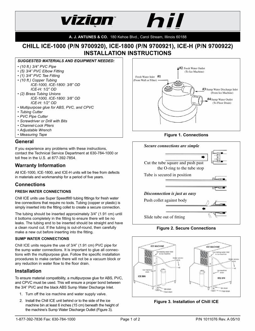
2. Install the Chill ICE unit behind or to the side of the ice machine bin at least 6 inches (15 cm) beneath the height of the machine’s Sump Water Discharge Outlet (Figure 3).
Fresh Water Outlet (To Ice Machine)
#3
#4
#2
#1
Sump Water Outlet (To Floor Drain)
Fresh Water Inlet (From Wall or Filter)
Sump Water Discharge Inlet (From Ice Machine)
Figure 1. Connections
Cut the tube square and push past the O-ring to the tube stop
Secure connections are simple
Tube is secured in position
Disconnection is just as easy
Push collet against body
Slide tube out of fitting
Figure 2. Secure Connections
Figure 3. installation of Chill iCE
1-877-392-7836 Fax: 630-784-1000 Page 1 of 2 P/N 1011076 Rev. A 05/10

A. J. ANTUNES & CO. 180 Kehoe Blvd., Carol Stream, Illinois 60188
Figure 4 Figure 5.
Figure 6. Figure 7.
NOTE: Do NOT mounting the Chill iCE unit above the ice machine’s sump water discharge outlet.
3. Use the included mounting straps to secure the Chill ICE unit to either the ice bin or to the wall. Otherwise, place the unit on the floor.
NOTE: health codes in some areas require the Chill iCE to be at least 6 inches (15 cm) off the floor.
4. Use a T connector to install a vent pipe, or vacuum breaker, at least 24 inches (60 cm) in length as close as possible to the sump drain exiting the ice machine (Figure 4)
NOTE; The Chill iCE will NOT function properly without a vent pipe.
5. Attach a PVC line from the vent pipe at the ice machine drain outlet to the Sump Water Discharge Inlet on the Chill ICE (connection #3). Be sure to plumb a vertical line down from the ice machine drain and THEN a horizontal line to the Chill ICE (Figure 5).
NOTE: Water will overflow into the ice bin if the line is installed horizontally after existing the ice machine.
6. Connect a PVC line to the Sump Water Outlet on the Chill ICE (connection #4) using a 90° fitting. Be sure to plumb a vertical line down THEN a horizontal line to the floor drain (Figure 6).
NOTE: Drain water will not flow properly if the line exiting the Chill iCE is horizontal.
7. Carefully cut the existing fresh water line from the wall or after the water filter. Leave enough tubing to reach from the back of the ice machine to the top of the Chill ICE unit.
8. Insert insulated tubing into the Fresh Water Outlet on the Chill ICE unit (connection #2).
NOTE: if you are unfamiliar with Speedfit® connectors, review the Connections section on page 1.
9. Insert the tubing containing the fresh water source into the Fresh Water Inlet on the Chill ICE (connection #1). If additional tubing is needed between the Chill ICE and the wall outlet or water filter, be sure to connect the tubing with a compression union (Figure 7).
10. Turn on the fresh water valve and check all connections for leaks. If you encounter any leaks, refer to the Troubleshooting guide.
11. Check the water supply to the sump inside the ice machine by depressing the float valve or by activating the solenoid water valve.
12. Check the PVC drain lines for leaks by pouring water through the vent pipe until it is seen exiting the Chill ICE unit into the floor drain.
13. Turn on the ice machine. If you encounter any leaks, refer to the Troubleshooting guide.
Troubleshooting Guide iSSUE: The water lines are leaking at the Speedfit® fittings.
The tubing inserted in the fitting is not pushed in all the way or the tubing end is out-of-round. Turn the water source off to relieve line pressure, then remove tubing from the fitting (see Connections section).
Inspect the end of the tubing to make certain there is a clean square cut and the tubing is perfectly round. The tubing should also be straight so it can be inserted completely (about 3/4” or 1.91 cm). Reinsert the tubing into the fitting and press in firmly until the tubing “bottoms” securely. Turn the water valve on and check again for leaks.
iSSUE: When the ice machine is turned on, there isn’t any water entering the sump to make ice.
Sometimes when the existing fresh water lines are cut and bent to be inserted into the Chill ICE, some particulate matter can be broken loose and cause the water supply within the ice machine to become clogged. Turn the water source valve off. Inspect all needle valves, filter screens, and any other water supply valves inside the machine. Remove any debris found, then turn the water source on and depress the float switch in the sump to make certain the restriction was removed.
iSSUE: When the ice machine is running, there is water overflowing out of the top of the vent pipe and the Chill iCE seems to be clogged.
Either extend the height of the vent pipe if space permits or use a larger diameter of PVC pipe in the existing space. Both will allow for a greater volume of water to rise in the vent pipe to overcome the air lock in the drain system.
1-877-392-7836 Fax: 630-784-1000 Page 2 of 2 P/N 1011076 Rev. A 05/10