ajacs catalog - welcome to ajacs
TRANSCRIPT


Die Springs - Inch Series Medium Pressure Blue
Part Number
Diameter Free Length Load
Hole O.D.
Rod I.D.
Inch Mm 50% Deflection
(lb)
1/10” Deflection
(lb) M-100 1 25.4 30.0 6.0 M-100A 1-1/4 31.8 33.8 5.4 M-101 3/8” 3/16” 1-1/2 38.1 30.0 4.0 M-101A 9.5mm 4.8mm 1-3/4 44.5 29.8 3.4 M-102 2 50.8 28.0 2.8 M-103 Wire
.039 x .070 2-1/2 63.5 30.0 2.4
M-104 3 76.2 31.5 2.1 M-105 12 304.8 36.0 0.6
M-110 1 25.4 55.0 11.0 M-110A 1-1/4 31.8 51.3 8.2 M-111 1/2” 9/32” 1-1/2 38.1 51.0 6.8 M-111A 12.7mm 7.1mm 1-3/4 44.5 52.5 6.0 M-112 2 50.8 55.0 5.5 M-113 Wire
.052 x .093 2-1/2 63.5 56.3 4.5
M-114 3 76.2 52.5 3.5 M-115 3-1/2 88.9 52.5 3.0 M-115A 4-1/2 114.3 56.3 2.5 M-115B 5-1/2 139.7 57.8 2.1 M-115C 6-1/2 165.1 45.5 1.4 M-115D 7-1/2 190.5 45.0 1.2 M-116 12 304.8 42.0 0.7
M-120 1 25.4 82.0 16.4 M-120A 1-1/4 31.8 80.0 12.8 M-121 5/8” 11/32” 1-1/2 38.1 81.0 10.8 M-121A 15.9mm 8.7mm 1-3/4 44.5 84.0 9.6 M-122 2 50.8 88.0 8.8 M-123 Wire
.069 x .109 2-1/2 63.5 75.0 6.0
M-124 3 76.2 84.0 5.6 M-125 3-1/2 88.9 84.0 4.8 M-126 4 101.6 88.0 4.4 M-127 12 304.8 96.0 1.6
M-1 1 25.4 156.0 31.2 M-1A 1-1/4 31.8 160.0 25.6 M-2 3/4” 3/8” 1-1/2 38.1 150.0 20.0 M-2A 19.1mm 9.5mm 1-3/4 44.5 154.0 17.6 M-3 2 50.8 144.0 14.4 M-4 Wire
.075 x .165 2-1/2 63.5 150.0 12.0
M-5 3 76.2 144.0 9.6 M-6 3-1/2 88.9 140.0 8.0 M-7 4 114.3 144.0 7.2 M-8 4-1/2 114.3 144.0 6.4 M-9 5 127.0 150.0 6.0 M-10 5-1/2 139.7 151.3 5.5 M-11 6 152.4 150.0 5.0 M-11B 6-1/2 165.1 146.3 4.5 M-11C 7-1/2 190.5 142.5 3.8 M-11A 12 304.8 144.0 2.4
Part Number
Diameter Free Length Load
Hole O.D.
Rod I.D.
Inch Mm 50% Deflection
(lb)
1/10” Deflection
(lb) M-12 1 25.4 275.0 55.0 M-12A 1-1/4 31.8 281.3 45.0 M-13 1” 1/2” 1-1/2 38.1 262.5 35.0 M-13A 25.4mm 12.7mm 1-3/4 44.5 262.5 30.0 M-14 2 50.8 260.0 26.0 M-15 Wire
.100 x .215 2-1/2 63.5 250.0 20.0
M-16 3 76.2 247.5 16.5 M-17 3-1/2 88.9 262.5 15.0 M-18 4 101.6 240.0 12.0 M-19 4-1/2 114.3 234.0 10.4 M-20 5 127.0 240.0 9.6 M-21 5-1/2 139.7 242.0 8.8 M-22 6 152.4 240.0 8.0 M-23 7 177.8 252.0 7.2 M-24 8 203.2 240.0 6.0 M-24A 12 304.8 240.0 4.0
M-36 1-1/2 38.1 372.0 49.6 M-36A 1-3/4 44.5 371.0 42.4 M-37 1-1/4” 5/8” 2 50.8 352.0 35.2 M-38 31.8mm 15.9mm 2-1/2 63.5 360.0 28.8 M-39 3 76.2 360.0 24.0 M-40 Wire
.115 x .285 3-1/2 88.9 350.0 20.0
M-41 4 101.6 352.0 17.6 M-42 4-1/2 114.3 360.0 16.0 M-43 5 127.0 340.0 13.6 M-44 5-1/2 139.7 352.0 12.8 M-45 6 152.4 360.0 12.0 M-46 7 177.8 364.0 10.4 M-47 8 203.2 352.0 8.8 M-48 10 254.0 360.0 7.2 M-48A 12 304.8 360.0 6.0
M-49 2 50.8 530.0 53.0 M-50 2-1/2 63.5 562.5 45.0 M-51 1-1/2” 3/4” 3 76.2 540.0 36.0 M-52 38.1mm 19.1mm 3-1/2 88.9 525.0 30.0 M-53 4 101.6 540.0 27.0 M-54 Wire
.135 x .345 4-1/2 114.3 517.5 23.0
M-55 5 127.0 525.0 21.0 M-55A 5-1/2 139.7 508.8 18.5 M-56 6 152.4 510.0 17.0 M-56A 7 177.8 507.5 14.5 M-57 8 203.2 512.0 12.8 M-58 10 254.0 500.0 10.0 M-58A 12 304.8 480.0 8.0
M-70 2-1/2 63.5 1250.0 100.0 M-71 3 76.2 1245.0 83.0 M-72 2” 1” 3-1/2 88.9 1134.0 64.8 M-73 50.8mm 25.4mm 4 101.6 1200.0 60.0 M-74 4-1/2 114.3 1192.5 53.0 M-75 Wire
.195 x .468 5 127.0 1175.0 47.0
M-76 5-1/2 139.7 1078.0 3.2 M-77 6 152.4 1170.0 39.0 M-79 7 117.8 1092.0 31.2 M-80 8 203.2 1140.0 28.5 M-82 10 254.0 1040.0 20.8 M-83 12 304.8 1050.0 17.5
LOAD DEFLECTION
Maximum Deflection: 50% of free length For Long Life 35% of free length Maximum Operation 40% of free length For Optimum Life 25% of free length Tablulated load values shown are near solid and are for design info only

Die Springs - Inch Series Medium High Pressure Red
LOAD DEFLECTION
Maximum Deflection: 37% of free length For Long Life 25% of free length Maximum Operation 30% of free length For Optimum Life 20% of free length Tablulated load values shown are near solid and are for design info only
Part Number
Diameter Free Length Load
Hole O.D.
Rod I.D.
Inch Mm 50% Deflec-
tion
1/10” Deflection
(lb) MHC-100 1 25.4 33.3 9.0 MHC-100A 1-1/4 31.8 33.8 7.3 MHC-101 3/8” 3/16” 1-1/2 38.1 37.2 6.7 MHC-101A 9.5mm 4.8mm 1-3/4 44.5 37.6 5.8 MHC-102 2 50.8 37.0 5.0 MHC-103 Wire
.046 x .073 2-1/2 63.5 38.9 4.2
MHC-104 3 76.2 33.3 3.0 MHC-105 12 304.8 40.0 0.9
MHC-110 1 25.4 62.2 16.8 MHC-110A 1-1/4 31.8 60.1 13.0 MHC-111 1/2” 9/32” 1-1/2 38.1 52.7 9.5 MHC-111A 12.7mm 7.1mm 1-3/4 44.5 55.0 8.5 MHC-112 2 50.8 55.5 7.5 MHC-113 Wire
.061 x .093 2-1/2 63.5 55.5 6.0
MHC-114 3 76.2 63.3 5.7 MHC-115 3-1/2 88.9 51.8 4.0 MHC-117 12 304.8 53.3 1.2
MHC-120 1 25.4 111.0 30.0 MHC-120A 1-1/4 31.8 99.4 21.5 MHC-121 5/8” 11/32” 1-1/2 38.1 105.5 19.0 MHC-121A 15.9mm 8.7mm 1-3/4 44.5 108.8 16.8 MHC-122 2 50.8 109.5 14.8 MHC-123 Wire
.08 x .123 2-1/2 63.5 106.4 11.5
MHC-124 3 76.2 111.0 10.0 MHC-125 3-1/2 88.9 110.1 8.5 MHC-126 4 101.6 112.5 7.6 MHC-127 12 304.8 119.9 2.7
MHC-1 1 25.4 185.0 50.0 MHC-1A 1-1/4 31.8 175.8 38.0 MHC-2 3/4” 3/8” 1-1/2 38.1 177.6 32.0 MHC-2A 19.1mm 9.5mm 1-3/4 44.5 186.5 28.8 MHC-3 2 50.8 183.5 24.8 MHC-4 Wire
.075 x .165 2-1/2 63.5 177.6 19.2
MHC-5 3 76.2 159.8 14.4 MHC-6 3-1/2 88.9 165.8 12.8 MHC-7 4 101.6 177.6 12.0 MHC-8 4-1/2 114.3 186.5 11.2 MHC-9 5 127.0 166.5 9.0 MHC-10 5-1/2 139.7 162.8 8.0 MHC-11 6 152.4 166.5 7.5 MHC-11A 12 304.8 159.8 3.6
Part Number
Diameter Free Length Load
Hole O.D.
Rod I.D.
Inch Mm 50% Deflection
(lb)
1/10” Deflection
(lb) MHC-12 1 25.4 281.2 76.0 MHC-12A 1-1/4 31.8 288.6 62.4 MHC-13 1” 1/2” 1-1/2 38.1 275.3 49.6 MHC-13A 25.4mm 12.7mm 1-3/4 44.5 284.9 44.0 MHC-14 2 50.8 296.0 40.0 MHC-15 Wire
.115 x .218 2-1/2 63.5 286.8 31.0
MHC-16 3 76.2 277.5 25.0 MHC-17 3-1/2 88.9 279.7 21.6 MHC-18 4 101.6 272.3 18.4 MHC-19 4-1/2 114.3 283.1 17.0 MHC-20 5 127.0 266.4 14.4 MHC-21 5-1/2 139.7 260.5 12.8 MHC-22 6 152.4 266.4 12.0 MHC-23 7 177.8 259.0 10.0 MHC-24 8 203.2 260.5 8.8 MHC-24A 12 304.8 275.3 6.2
MHC-36 1-1/2 38.1 634.9 114.4 MHC-36A 1-3/4 44.5 652.7 100.8 MHC-37 1-1/4” 5/8” 2 50.8 639.4 86.4 MHC-38 31.8mm 15.9mm 2-1/2 63.5 577.2 62.4 MHC-39 3 76.2 568.3 51.2 MHC-40 Wire
.156 x .281 3-1/2 88.9 569.8 44.0
MHC-41 4 101.6 544.6 36.8 MHC-42 4-1/2 114.3 532.8 32.0 MHC-43 5 127.0 536.5 29.0 MHC-44 5-1/2 139.7 537.2 26.4 MHC-45 6 152.4 555.0 25.0 MHC-46 7 177.8 518.0 20.0 MHC-47 8 203.2 544.6 18.4 MHC-48 10 254.0 536.5 14.5 MHC-48A 12 304.8 550.6 12.4
MHC-49 2 50.8 799.2 108.0 MHC-50 2-1/2 63.5 791.8 85.6 MHC-51 1-1/2” 3/4” 3 76.2 692.6 62.4 MHC-52 38.1mm 19.1mm 3-1/2 88.9 683.8 52.8 MHC-53 4 101.6 710.4 48.0 MHC-54 Wire
.187 x .312 4-1/2 114.3 719.3 43.2
MHC-55 5 127.0 680.8 36.8 MHC-55A 5-1/2 139.7 700.0 34.4 MHC-56 6 152.4 674.9 30.4 MHC-56A 7 177.8 683.8 26.4 MHC-57 8 203.2 651.2 22.0 MHC-58 10 254.0 651.2 17.6 MHC-58A 12 304.8 639.4 14.4
MHC-70 2-1/2 63.5 1095.2 118.4 MHC-71 3 76.2 1065.6 96.0 MHC-71 2” 1” 3-1/2 88.9 1036.0 80.0 MHC-73 50.8mm 25.4mm 4 101.6 982.7 66.4 MHC-74 4-1/2 114.3 999.0 60.0 MHC-75 Wire
.225 x .437 5 127.0 1036.0 56.0
MHC-76 5-1/2 129.7 1025.6 50.4 MHC-77 6 152.4 1047.8 47.2 MHC-79 7 177.8 1036.0 40.0 MHC-80 8 203.2 1041.9 35.2 MHC-82 10 254.0 962.0 26.0 MHC-83 12 304.8 994.6 22.4

Die Springs - Inch Series High Pressure Gold
LOAD DEFLECTION
Maximum Deflection: 30% of free length For Long Life 20% of free length Maximum Operation 25% of free length For Optimum Life 15% of free length Tablulated load values shown are near solid and are for design info only
Part Number
Diameter Free Length Load
Hole O.D.
Rod I.D.
Inch Mm 50% Deflection
(lb)
1/10” Deflection
(lb) H-100 1 25.4 33.0 11.0 H-100A 1-1/4 31.8 36.8 9.8 H-101 3/8” 3/16” 1-1/2 38.1 36.0 8.0 H-101A 9.5mm 4.8mm 1-3/4 44.5 44.1 8.4 H-102 2 50.8 43.2 7.2 H-103 Wire
.054 x .072 2-1/2 63.5 41.3 5.5
H-104 3 76.2 37.8 4.2 H-105 12 304.8 43.2 1.2
H-110 1 25.4 70.8 23.6 H-110A 1-1/4 31.8 69.8 18.6 H-111 1/2” 9/32” 1-1/2 38.1 69.8 15.5 H-111A 12.7mm 7.1mm 1-3/4 44.5 72.5 13.8 H-112 2 50.8 66.0 11.0 H-113 Wire
.072 x .095 2-1/2 63.5 63.0 8.4
H-114 3 76.2 66.6 7.4 H-115 3-1/2 88.9 63.0 6.0 H-117 12 304.8 57.6 1.6
H-120 1 25.4 127.2 42.4 H-120A 1-1/4 31.8 111.0 29.6 H-121 5/8” 11/32” 1-1/2 38.1 122.4 27.2 H-121A 15.9mm 8.7mm 1-3/4 44.5 126.0 24.0 H-122 2 50.8 124.8 20.8 H-123 Wire
.093 x .125 2-1/2 63.5 127.5 17.0
H-124 3 76.2 129.6 14.4 H-125 3-1/2 88.9 128.1 12.2 H-126 4 101.6 129.6 10.8 H-127 12 304.8 108.0 3.0
H-1 1 25.4 324.0 108.0 H-1A 1-1/4 31.8 330.0 88.0 H-2 3/4” 3/8” 1-1/2 38.1 295.2 65.6 H-2A 19.1mm 9.5mm 1-3/4 44.5 315.0 60.0 H-3 2 50.8 297.6 49.6 H-4 Wire
.125 x .165 2-1/2 63.5 300.0 40.0
H-5 3 76.2 306.0 34.0 H-6 3-1/2 88.9 294.0 28.0 H-7 4 101.6 300.0 25.0 H-8 4-1/2 114.3 297.0 22.0 H-9 5 127.0 292.5 19.5 H-10 5-1/2 139.7 280.5 17.0 H-11 6 152.4 288.0 16.0 H-11A 12 304.8 288.0 8.0
Part Number
Diameter Free Length Load
Hole O.D.
Rod I.D.
Inch Mm 50% Deflection
(lb)
1/10” Deflection
(lb) H-12 1 25.4 624.0 208.0 H-12A 1-1/4 31.8 642.0 171.2 H-13 1” 1/2” 1-1/2 38.1 532.8 118.4 H-13A 25.4mm 12.7mm 1-3/4 44.5 546.0 104.0 H-14 2 50.8 540.0 90.0 H-15 Wire
.158 x .225 2-1/2 63.5 510.0 68.0
H-16 3 76.2 489.6 54.4 H-17 3-1/2 88.9 478.8 45.6 H-18 4 101.6 480.0 40.0 H-19 4-1/2 114.3 475.2 35.2 H-20 5 127.0 468.0 31.2 H-20A 5-1/2 139.7 475.2 28.8 H-21 6 152.4 460.8 25.6 H-21A 7 177.8 470.4 22.4 H-22 8 203.2 460.8 19.2 H-22A 12 304.8 432.0 12.0
H-36 1-1/2 38.1 954.0 212.0 H-36A 1-3/4 44.5 953.4 181.6 H-37 1-1/4” 5/8” 2 50.8 897.6 149.6 H-38 31.8mm 15.9mm 2-1/2 63.5 882.0 117.6 H-39 3 76.2 856.8 95.2 H-40 Wire
.200 x .295 3-1/2 88.9 789.6 75.2
H-41 4 101.6 796.8 66.4 H-42 4-1/2 114.3 788.4 58.4 H-43 5 127.0 795.0 53.0 H-44 5-1/2 139.7 778.8 47.2 H-45 6 152.4 763.2 42.4 H-46 7 177.8 772.8 36.8 H-47 8 203.2 787.2 32.8 H-48 10 254.0 768.9 25.6 H-48A 12 304.8 748.8 20.8
H-49 2 50.8 1142.4 190.4 H-50 2-1/2 63.5 1162.5 155.0 H-51 1-1/2” 3/4” 3 76.2 1170.0 130.0 H-52 38.1mm 19.1mm 3-1/2 88.9 1117.2 106.4 H-53 4 101.6 1094.4 91.2 H-54 Wire
.225 x .350 4-1/2 114.3 1058.4 78.4
H-55 5 127.0 1068.0 71.2 H-55A 5-1/2 129.7 1056.0 64.0 H-56 6 152.4 1051.2 58.4 H-56A 7 177.8 1041.6 49.6 H-57 8 203.2 1036.8 43.2 H-58 10 254.0 1032.0 34.4 H-58A 12 304.8 1036.8 28.8
H-70 2-1/2 63.5 1950.0 260.0 H-71 3 76.2 1800.0 200.0 H-72 2” 1” 3-1/2 88.9 1785.0 170.0 H-73 50.8mm 25.4mm 4 101.6 1800.0 150.0 H-74 4-1/2 114.3 1620.0 120.0 H-75 Wire
.280 x .470 5 127.0 1650.0 110.0
H-76 5-1/2 139.7 1650.0 100.0 H-77 6 152.4 1692.0 94.0 H-79 7 177.8 1722.0 82.0 H-80 8 203.2 1752.0 73.0 H-82 10 254.0 1650.0 55.0 H-83 12 304.8 1512.0 42.0

Die Springs - Inch Series Extra High Pressure Green
LOAD DEFLECTION
Maximum Deflection: 25% of free length For Long Life 17% of free length Maximum Operation 20% of free length For Optimum Life 15% of free length Tablulated load values shown are near solid and are for design info only
Part Number
Diameter Free Length Load
Hole O.D.
Rod I.D.
Inch Mm 50% Deflection
(lb)
1/10” Deflection
(lb) XH-100 1 25.4 55.0 22.0 XH-100A 1-1/4 31.8 50.0 16.0 XH-101 3/8” 3/16” 1-1/2 38.1 46.9 12.5 XH-101A 9.5mm 4.8mm 1-3/4 44.5 50.3 11.5 XH-102 2 50.8 45.0 9.0 XH-103 Wire
.059 x .080 2-1/2 63.5 43.8 7.0
XH-104 3 76.2 48.8 6.5 XH-105 12 304.8 45.0 1.5
XH-110 1 25.4 80.0 32.0 XH-110A 1-1/4 31.8 75.0 24.0 XH-111 1/2” 9/32” 1-1/2 38.1 75.0 20.0 XH-111A 12.7mm 7.1mm 1-3/4 44.5 74.4 17.0 XH-112 2 50.8 70.0 14.0 XH-113 Wire
.084 x .097 2-1/2 63.5 71.9 11.5
XH-114 3 76.2 67.5 9.0 XH-115 3-1/2 88.9 70.0 8.0 XH-116 12 304.8 5.0 2.5
XH-120 1 25.4 157.5 63.0 XH-120A 1-1/4 31.8 146.9 47.0 XH-121 5/8” 11/32” 1-1/2 38.1 142.5 38.0 XH-121A 15.9mm 8.7mm 1-3/4 44.5 140.0 32.0 XH-122 2 50.8 145.0 29.0 XH-123 Wire
.110 x .126 2-1/2 63.5 137.5 22.0
XH-124 3 76.2 142.5 19.0 XH-125 3-1/2 88.9 140.0 16.0 XH-126 4 101.6 135.0 13.5 XH-127 12 304.8 135.0 4.5
XH-1 1 25.4 350.0 140.0 XH-1A 1-1/4 31.8 343.8 110.0 XH-2 3/4” 3/8” 1-1/2 38.1 333.8 89.0 XH-2A 19.1mm 9.5mm 1-3/4 44.5 328.1 75.0 XH-3 2 50.8 3430.0 68.0 XH-4 Wire
.135 x .165 2-1/2 63.5 312.5 50.0
XH-5 3 76.2 303.8 40.5 XH-6 3-1/2 88.9 301.9 34.5 XH-7 4 101.6 300.0 30.0 XH-8 4-1/2 114.3 298.1 26.5 XH-9 5 127.0 293.8 23.5 XH-10 5-1/2 139.7 295.6 21.5 XH-11 6 152.4 292.5 19.5 XH-11A 12 304.8 285.0 9.5
Part Number
Diameter Free Length Load
Hole O.D.
Rod I.D.
Inch Mm 50% Deflection
(lb)
1/10” Deflection
(lb) XH-13 1-1/2 38.1 600.0 160.0 XH-14 2 50.8 580.0 116.0 XH-15 1” 1/2” 2-1/2 63.5 560.0 89.6 XH-16 25.4mm 12.7mm 3 76.2 552.0 73.6 XH-17 3-1/2 88.9 546.0 62.4 XH-18 Wire
.188 x .225 4 101.6 552.0 55.2
XH-19 4-1/2 114.3 549.0 48.8 XH-20 5 127.0 540.0 43.2 XH-21 6 152.4 540.0 36.0 XH-22A 12 304.8 528.0 17.6
XH-37 2 50.8 960.0 192.0 XH-38 2-1/2 63.5 900.0 144.0 XH-39 1-1/4” 5/8” 3 76.2 888.0 118.4 XH-40 31.8mm 15.9mm 3-1/2 88.9 882.0 100.8 XH-41 4 101.6 840.0 84.0 XH-42 Wire
.225 x .295 4-1/2 114.3 882.0 78.4
XH-43 5 127.0 850.0 68.0 XH-45 6 152.4 840.0 56.0 XH-47 8 203.2 832.0 41.6 XH-48 10 254.0 840.0 33.6 XH-48A 12 304.8 92.0 26.4
XH-49 2 50.8 1880.0 376.0 XH-50 2-1/2 3.5 1840.0 294.4 XH-51 1-1/2” 3/4” 3 76.2 1734.0 231.2 XH-52 38.1mm 19.1mm 3-1/2 88.9 1715.0 196.0 XH-53 4 101.6 1712.0 171.2 XH-54 Wire
.300 x .350 4-1/2 114.3 1665.0 148.0
XH-55 5 127.0 1700.0 136.0 XH-56 6 152.4 1656.0 110.4 XH-57 8 203.2 1616.0 80.8 XH-58 10 254.0 1680.0 67.2 XH-58A 12 304.8 1632.0 54.4
XH-70 2-1/2 63.5 2385.0 381.6 XH-71 3 76.2 2340.0 312.0 XH-72 3-1/2 88.9 2226.0 254.4 XH-73 50.8mm 25.4mm 4 101.6 2200.0 220.0 XH-74 4-1/2 114.3 2124.0 188.8 XH-75 Wire
.365 x .460 5 127.0 2160.0 172.8
XH-77 6 152.4 2124.0 141.6 XH-80 8 203.2 2000.0 100.0 XH-82 10 254.0 2100.0 84.0 XH-83 12 304.8 2136.0 71.2

800.968.6868
616.452.1469
Fax 616.452.1386
Die Button Shims By: B&G Industries / Redishims
Die Button
Size
Shim Size
.010 .015 .020
Shim Size
.025
Shim Size
.030
Shim Size
.060
X X X
RS 1/4 Dia X X X
RS 5/16 Dia X X X
RS 3/8 Dia X X X
RS 7/16 Dia X X X
RS 1/2 Dia X X X X
RS 5/8 Dia X X X X
RS 3/4 Dia X X X X
RS 7/8 Dia X X X X
RS 1” Dia X X X X
RS 1-1/4 Dia X X X X
RS 1-1/2 Dia X X X X
All Shims are available in quantities of 20, 50 or 100
All shims are .003 - .005 under button size For Easy Assembly
Kits available which include .010 .015 and .020 thickness 720 Shims total (RS Kit 720) Kits available which include .025 .030 and .060 thickness 620 Shims total (RS Kit 620)
Typical Order Example: RS 1/4 x .010

800.968.6868
616.452.1469
Fax 616.452.1386
Die Button Shims - Metric By: B&G Industries / Redishims
Die Button
Size
Shim Size
.25 .40 .50
Shim Size
.65
Shim Size
.80
Shim Size
1.5
RS 08 Dia X X X
RS 10 Dia X X X
RS 13 Dia X X X X
RS 16 Dia X X X X
RS 20 Dia X X X X
RS 22 Dia X X X X
RS 25 Dia X X X X
RS 32 Dia X X X X
RS 38 Dia X X X X
All Shims are available in quantities of 20, 50 or 100
All shims are .1 - .12 under button size For Easy Assembly
Kits available which include .25 .40 and .50 thickness 540 Shims total (RS Kit 540) Kits available which include .65 .80 and 1.5 thickness 460 Shims total (RS Kit 460)
Typical Order Example: RS 08 x .25
All dimensions in millimeters

800.968.6868
616.452.1469
Fax 616.452.1386
Solid Bronze Ampco 18
C Dimension—Width
1 1-1/4 1-1/2 2 2-1/2 3 4 5 6
1/4 ● ● ● ● ● ● ● 3/8 ● ● ● ● ● ● ● ● 1/2 ● ● ● ● ● ● ● ● 5/8 ● ● ● ● ● ● ● ● 3/4 ● ● ● ● ● ●
1 ● ● ● ● 1-3/4 ●
B Dimen-sion
B
C
● Available Sizes
Special sizes available. Contact Ajacs customer service for details.
Cast on outside dimensions with +.030 minimum stock. Saw cut to specified length

800.968.6868
616.452.1469
Fax 616.452.1386
Pilot Retainer
English Metric
Part No D Screw/Dowel Part No D Screw/Dowel AT-375P .375 5/16 AT-10P 10mm 8mm AT-500P .500 5/16 AT-13P 13mm 8mm AT-625P .625 5/16 AT-16P 16mm 8mm **All locations are same English or Metric **Specials available upon request
Saves Time and Money
Standardize Components
No Hand Fitting Required
Ejector Pins and Springs Included
Pilot Sold Separately
Cad data available for download at:
http://www.ajacs.com/mediafile/pilotret.zip
DWG file (dwg) Parasolid Text (x_t) STEP(stp) VISI-Series Work File (wkf)

800.968.6868
616.452.1469
Fax 616.452.1386
Kicker Spring-Pins
Economy - Versatility - Ease of Assembly Available in Standard and Metric Sizes
Typical Applications
Unit Consists of Spring, Pin and Set Screw
Unit No. Quantity Pin Pin Hole Spring Spring Hole Screw
GPM-508 25 0.508 Dia. x 76.2 0.635 1.96 Dia. x 57.2 2.06 m2.5 x 5mm
GPM-660 25 0.660 Dia. x 76.2 0.787 2.39 Dia. x 57.2 2.49 m3 x 5mm
GPM-1040 25 1.004 Dia. x 76.2 1.17 3.20 Dia. x 59.2 3.30 m4 x 5mm
GPM-1400 25 1.40 Dia. x 101.6 1.57 4.10 Dia. x 69.9 4.19 m5 x 5mm
GPM-2180 25 2.18 Dia. x 101.6 2.39 4.90 Dia. x 76.2 5.00 m6 x 6mm
GPM-3760 25 3.76 Dia. x 101.6 3.96 8.41 Dia. x 88.9 8.51 m10 x 8mm
Reduce your costs with this simple slug ejection method. Just cut the spring and pin to suit your application.
Unit No. Quantity Pin Pin Hole Spring Spring Hole Screw
GP-20 25 .020 Dia. x 3 .025 .082 Dia. x 2 .086 3-48 x 3/16
GP-26 25 .026 Dia. x 3 .031 .105 Dia. x 2-1/4 7/64 5-40 x 3/16
GP-41 25 .041 Dia. x 3 .046 .140 Dia. x 2-1/2 .144 8-32 x 3/16
GP-55 25 .055 Dia. x 4 .062 .162 Dia. x 2-3/4 .166 10-32 x 3/16
GP-86 25 .086 Dia. x 4 .094 .217 Dia. x 3 .221 1/4-28 x 1/4
GP-148 25 .148 Dia. x 4 .156 .308 Dia. x 3-1/2 .312 3/8-16 x 5/16
800.968.6868
616.452.1469
Fax 616.452.1386
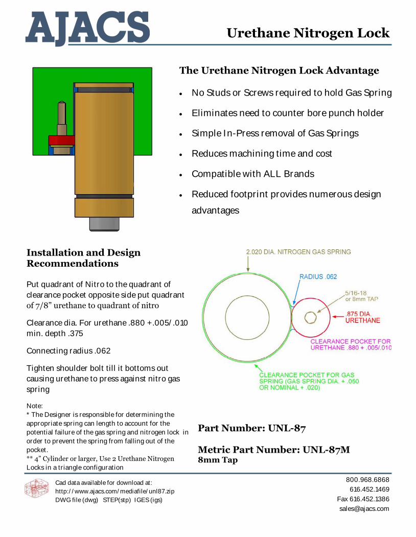
Installation and Design Recommendations Put quadrant of Nitro to the quadrant of
clearance pocket opposite side put quadrant
of 7/8” urethane to quadrant of nitro
Clearance dia. For urethane .880 +.005/.010
min. depth .375
Connecting radius .062
Tighten shoulder bolt till it bottoms out
causing urethane to press against nitro gas
spring
Note:
* The Designer is responsible for determining the
appropriate spring can length to account for the
potential failure of the gas spring and nitrogen lock in
order to prevent the spring from falling out of the
pocket.
** 4” Cylinder or larger, Use 2 Urethane Nitrogen
Locks in a triangle configuration
The Urethane Nitrogen Lock Advantage No Studs or Screws required to hold Gas Spring
Eliminates need to counter bore punch holder
Simple In-Press removal of Gas Springs
Reduces machining time and cost
Compatible with ALL Brands
Reduced footprint provides numerous design
advantages
Urethane Nitrogen Lock
Cad data available for download at:
http://www.ajacs.com/mediafile/unl87.zip
DWG file (dwg) STEP(stp) IGES (igs)
Part Number: UNL-87 Metric Part Number: UNL-87M 8mm Tap

800.968.6868
616.452.1469
Fax 616.452.1386
Keys
Cad data available for download at:
http://www.ajacs.com/mediafile/keys.zip
Part No. AT100K
Part No. AT750K
Part No. AT500K

800.968.6868
616.452.1469
Fax 616.452.1386
Keys - Metric
MATERIAL: ISO 683/18 - C20
Part No. Style A h9 B C ± 0.3 ØD ØE F +0.4 Socket Head Cap Screw Required
(not provided)
AT202080K A 20 20 80 15 9 8 M8 x 125 x 20 LG
AT252550K A 25 25 50 18 11 10 M10 x 1.50 x 30 LG
AT252580K A 25 25 80 18 11 10 M10 x 1.50 x 30 LG
STYLE A STYLE B (Use Only for Backup)

800.968.6868
616.452.1469
Fax 616.452.1386
Keys - Metric
Cad data available for download at:
http://www.ajacs.com/mediafile/keys.zip
Part No. AT500K - M

800.968.6868
616.452.1469
Fax 616.452.1386
Ejector Pins
Tolerances (Inch)
Pin Diameter (D) +.000
Head Diameter (H) +.000
Head Thickness (T) +.000
Length (L) +.000
Catalog
Number
D
Pin
Dia
H
Head
Dia
T
Head
Thick-
ness
L=Length
4” 6” 10” 10” 14” 14” 18” 18” 25”
L04 L06 L10 L105
‘D’
.005
Over Sized
L14 L145
‘D’
.005
Over Sized
L18 L185
‘D’
.005
Over Sized
-25
EP04 3/64 5/32 1/8 ●***
EP06 1/16 3/16 1/8 ●***
EP07 5/64 13/64 1/8 ●***
EP09 3/32 7/32 1/8 ●*** ●***
EP10 7/64 15/64 1/8 ●*** ●***
EP12 1/8 1/4 1.8 ● ● ● ● ● ●
EP14 9/64 1/4 1/8 ● ●
EP15 5/32 9/32 5/32 ● ● ● ● ● ● ●
EP17 11/64 11/32 3/16 ● ●
EP18 3/16 3/8 3/16 ● ● ● ● ● ● ● ●
EP20 13/64 3/8 3/16 ● ●
EP21 7/32 13/32 3/16 ● ● ● ● ● ●
EP23 15/64 13/32 3/16 ● ●
EP25 1/4 7/16 3/16 ● ● ● ● ● ● ● ● ●
EP26 17/64 7/16 1/4 ● ● ●
EP28 9/32 7/16 1/4 ● ● ● ● ● ●
EP29 19/64 1/2 1/4 ● ●
EP31 5/16 1/2 1/4 ● ● ● ● ● ● ● ● ●
EP32 21/64 9/16 1/4 ● ● ●
EP34 11/32 9/16 1/4 ● ● ● ● ●
EP35 23/64 5/8 1/4 ● ●
EP37 3/8 5/8 1/4 ● ● ● ● ● ● ● ● ●
EP40 13/32 11/16 1/4 ● ● ● ● ● ●
EP43 7/16 11/16 1/4 ● ● ● ● ● ● ●
EP46 15/32 3/4 1/4 ● ● ● ●
EP50 1/2 3/4 1/4 ● ● ● ● ● ● ● ●
EP56 9/16 13/16 1/4 ● ● ● ● ●
EP62 5/8 7/8 1/4 ● ● ● ● ●
EP68 11/16 15/16 1/4 ● ● ●
EP75 3/4 1 1/4 ● ● ● ● ●
EP87 7/8 1-1/8 1/4 ● ● ●
EP90 1 1-1/4 1/4 ● ● ● ● ●
Sample Catalog Number: EP14L10
EP14L105 for Oversized Pin
Steel is heat treated, ground, nitrided and polished. Pin body has a
surface hardness of 65-80 Rc and a core hardness of 35-40 Rc. Head
hardness is 25-30 Rc
*** 2” shoulder standard on ejector pins under 1/8 Diameter. Add P to part
number for no shoulder, add S to part number for 1/2” shoulder
Example: EP06L06P ( No Shoulder)
Example: EP06L06S (1/2” Shoulder)


800.968.6868
616.452.1469
Fax 616.452.1386
Urethane Blank Stripper 90.45.30
Material: Polyurethane 92 +/- 2 Shore A
Strip is 400mm long and has 8 segments
Roll pin (Part No: 90.10.45-1050)is required for every 50mm of stripper installed
Z Drill, No Ream
90.10.45-1050
67
+ 1m
m
- 1m
m

800.968.6868
616.452.1469
Fax 616.452.1386
Stop Blocks
Part No. D L +/- .002 LD CB T
AT250SB-CB 2.500 1.25—10.0 0.050 0.750
AT300SB-CB 3.000 1.25—10.0 0.050 0.750
AT250SB-T 2.500 1.25—10.0 0.050 1/2—13
AT300SB-T 3.000 1.25—10.0 0.050 1/2—13
AT250SB-MT 2.500 1.25-10.0 0.050 M12 x 1.75
AT300SB-MT 3.000 1.25-10.0 0.050 M12 x 1.75
How to Order:
Part Number + L Dimension + LD Dimension (Optional) + CB Dimension (Optional)
Example: AT250SB-CB L=6.500
Material: CRS Milled Finish
+/- .002

800.968.6868
616.452.1469
Fax 616.452.1386
Pad Mounted Pilots - English
Part No. D L OAL Tap
DP-37 0.375 1.000 1.500 10-24 x .75
DP-50 0.500 1.000 1.625 1/4-20 x .75
DP-62 0.625 1.000 1.750 1/4-20 x .75
DP-75 0.750 1.000 1.875 5/16-18 x .75

800.968.6868
616.452.1469
Fax 616.452.1386
Pad Mounted Pilots - Metric
Part No. D L OAL Tap
DP-10 10 25 37.76 6mm x 16mm
DP-13 13 25 41.88 6mm x 16mm
DP-16 16 25 46 6mm x 16mm

800.968.6868
616.452.1469
Fax 616.452.1386
Die Storage Blocks
Part No A Dia B
65-450-BASE 5.50 5/8-11
65-450-BASE-16M 5.50 M16-2
65-450-BASE-20M 5.50 M20-2.5
Part No A Dia B C
55-350-A 3.50 5.50 5/8-11
65-350-A 3.50 6.50 5/8-11
65-350-B 3.50 6.50 3/4-10
65-350-20M 3.50 6.50 M20-2.5
M-1443 3.50 8.00 M16-2
50-400-B 4.00 5.00 3/5-10
50-400-20M 4.00 5.00 M20-2.5
05-55-400 4.00 5.50 5/8-11
65-400-A 4.00 6.50 5/8-11
55-450-A 4.50 5.50 5/8-11
60-450-A 4.50 6.00 5/8-11
05-475-400 4.00 4.75 5/8-11
65-450-A 4.50 6.50 5/8-11
65-450-B 4.50 6.50 3/4-10
65-450-20M 4.50 6.50 M20-2.5
M-1444 4.50 8.00 M16-2
Cad Data available for download
http://www.ajacs.com/mediafile/diestorage.zip
800.968.6868
616.452.1469
Fax 616.452.1386
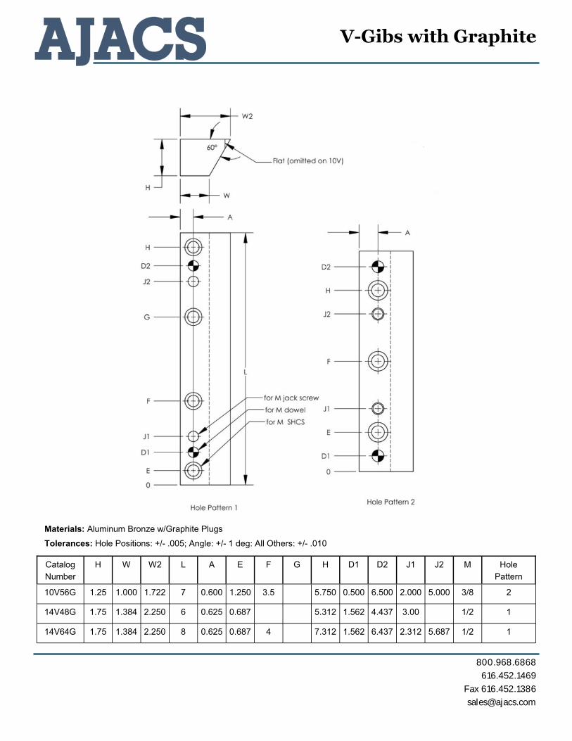
V-Gibs with Graphite
Catalog Number
H W W2 L A E F G H D1 D2 J1 J2 M Hole Pattern
10V56G 1.25 1.000 1.722 7 0.600 1.250 3.5 5.750 0.500 6.500 2.000 5.000 3/8 2
14V48G 1.75 1.384 2.250 6 0.625 0.687 5.312 1.562 4.437 3.00 1/2 1
14V64G 1.75 1.384 2.250 8 0.625 0.687 4 7.312 1.562 6.437 2.312 5.687 1/2 1
Materials: Aluminum Bronze w/Graphite Plugs
Tolerances: Hole Positions: +/- .005; Angle: +/- 1 deg: All Others: +/- .010

800.968.6868
616.452.1469
Fax 616.452.1386
Spring Probes, Block Probes and Magnetic Base
KBP2001 Block Probe Assembly
Replacement Spring:
KBP2001 SPRING
KMP38 Probe Stand Post and Magnet ***Probe and Spring Not Included***
Components:
KMP38-SJ8 Swivel Joint (1/2” Post Hole, 3/8” Spring Probe, One Hole)
KMP38-SJ11 Swivel Joint (1/2” Post Hole, 1/2” Spring Probe, Two Hole)
KMP38-ROD
(1/2” Rod)
KMP38-1200 (200lb “Stay-Put” Magnet)
KSP2000 Spring Probe Assembly
Replacement Spring Options:
KSP2000 SPRING Standard Spring Included with Assembly
KSP2000HD SPRING Heavy Duty Spring


800.968.6868
616.452.1469
Fax 616.452.1386
Ball Bearing Bushings and Retainers Producto
Series 500 Ball Bearing Assemblies are designed for the pin to
be installed in the die shoe. All components are manufactured to
the highest levels of quality and precsion. Bushings are precision
ground on both ID and OD to close tolerances. All assemblies
use Producto Master guide pins. The result is reliable and
consistent preloads between pin, bushing and retainer
Series 500 Ball Bearing Bushings and Retainers
Part Name
Nominal Pin Dia O.D. Length Max
Stroke Retainer
Part Number Length "RL"
Bushing Part Number
Assembly Part Number
PD100.1875 1.000 1.875 3.437 2.25 60-08613 3.250 61-00600 60-06949 PD125.2125 1.250 2.125 3.937 2.75 60-08612 3.750 61-00601 60-06950 PD150.2625 1.500 2.625 4.187 2.75 60-08611 4.000 61-00602 60-06951


800.968.6868
616.452.1469
Fax 616.452.1386
Set Screw Type SHED-IT™ No Pre-Load Required
P/N SET SCREW TAPPING DEPTH
RECOMMENDED DIAMETER THROUGH
LENGTH
SS-.050-83A 6-32 x 5/16 .343 MIN. No. 52 Drill .063 Dia. 3"
SS-.062-83A 8-32 x 5/16 .343 MIN. No. 49 Drill .073 Dia. 3"
SS-.093-83A 10-32 x 5/16 .343 MIN. No. 38 Drill .101 Dia. 3"
SS-.125-83A 1/4-28 x 3/8 .406 MIN. No. 29 Drill .136 Dia. 3"
Headed Type SHED-IT™ No Pre-Load Required
P/N HEAD DIMENSION
C'DRILL DIA. + DEPTH
RECOMMENDED DIAMETER THROUGH
LENGTH
HD-.050-83A .078 x .250 .109 x .265 No. 52 Drill .063 Dia. 3"
HD-.062-83A .093 x .250 .110 x .265 No. 49 Drill .073 Dia. 3"
HD-.093-83A .125 x .250 .140 x .265 No. 38 Drill .101 Dia. 3"
HD-.125-83A .156 x .250 .173 x .265 No. 29 Drill .136 Dia. 3"
Shed-It™

Paintable Release Agent #1504 An excellent mold release for all types of plastic molding. It permits immediate post decorating of most plastic components, provides more releases per appli-cation at less cost and saves time in high speed plastic production by eliminating the product clean-up operation. It is recommended for use with polystyrene, polycar-bonate, Noryl, ABS, PVC and polyolefins.
Net Wt. 11 oz - NO CFC
Mold Saver #1706Loosens rust and corrosion making it easy to separate parts where there is metal to metal contact. Formulated with corro-sion inhibitors to protect metal surfaces. No sticky residue, cleans, protects, lubricates, and displaces moisture.
Net Wt. 15 oz - NO CFC
Tool Towels #7001Specifically designed and engineered for the plasitc molding and mold build-ing environments. TOOL TOWELS wipe away all particles found in normal modling applications. No need to potentially contaminate your mold with a dirty shop rag while cleaning a vent, runner, parting line or the mold while the tool is in production. TOOL TOWELS are designed to clean this grime and more. The best part is how you throw them away! Perfect for all non-porous tool steels, aluminum and most surfaces found in manufacturing environments. Non-abrasive, cloth free and disposable. Works even more effectively when used in conjunction with Mold Degreaser #1605
Degreaser #1605Formulated as a strong, effec-tive degreaser where build-up of grease, oil, dirt, grim and other unwanted substances are encounterered. This strong action product can be sprayed on the surface to breakdown, wash away and clean grease from equipment, work areas, metal parts and any surface needing to be degrease in the manufacturing process only.
Net Wt. 14 oz - NO CFC
Silicon Mold Release #1302 A universal, silicone-type release agent recommended for injection, RIM, rotational molders as well as extruders and vacuum formers. This product can be used with all common resins. This silicone, as well as all others, may interfere with a post-decorating step. Not recommended where painting, metalizing, or bonding of components may be required.
Net Wt. 9 oz - NO CFC

TDX is a coating process ideally suited for severe metal forming applications. The TDX coating is applied in a molten salt bath resulting in a very uniform and smooth layer of carbides. The TDX carbides are metallurgically bonded to the tooling resulting in extremely high adhesion strength and peel resistance. With a hardness value of 4200 Vickers, the TDX coating can greatly extend the life of manufacturing tooling.
TDX Coating
The TDX Coating Advantage
Longer Tool Life Lower Tooling Expenditures
Decrease in Wear and Galling Increased Uptime
Improved Part Finish Higher Quality Parts
Superior Adhesion Excellent Peel Resistance
Molten Salt Bath Tool Steel
TDX Carbide Forming Elements Carbon Diffusion
TDX Coating Layer
TDX coating on top of tooling
TDX Coating process
TDX coated form blocks
������������
�������������
������������
�������������

Good TDX Applications
Severe Metal Stamping Stainless Steel High Strength Materials (HSLA)
Hydroforming
Roll Forming
Extrusion
Tube Forming
Piercing / Trim Details
Cold Forging
Form Punches
Why Use Tool Dynamics?
Experience. With over 100 years of combined experience with TD/TRD coating processes, our employees have the knowledge and skills required to provide the highest quality coatings available in the industry. We are continuously improving our coating to ensure the TDX coating process offers the highest level of quality and performance. Our experienced staff gives Tool Dynamics a competitive advantage.
Value. Our coating process has been engineered to provide your company with the highest value available in the industry. The TDX coating offers the best performance in severe metal forming applications often extending the life of tooling by 5 to 10 times. By offering a high level of performance coupled with an affordable price structure, Tool Dynamics is an industry leader in value.
In-House Capabilities. Since the founding of our company in 2001, we have strived to offer not only the highest value in the TD/TRD coating industry, but also to have the best turn around time available. Having such capabilities as in-house vacuum heat treatment, in-house polishing, and in-house tool repair services gives Tool Dynamics the ability to have the quickest turn around time available in the TD/TRD coating industry.
DIFFERENCE… #1 in Quality, Performance, Price,
and Lead-time
In-house Vacuum Heat Treatment
In-house Quality Department
Knowledgeable Sales Staff
THE
Punch applications
High pressure metal forming applications
In-house vacuum heat treatment
835 South Marr Road Columbus, IN 47201
Phone.(812) 379-4243 Fax.(812) 379-4222
������������
�������������
������������
�������������

TDX Coating: Frequently Asked Questions
What exactly is TDX?TDX is a coating process that diffuses a layer of carbides onto and into the surface of the tooling. The TDX layer is metallurgically bonded to the tooling providing superior adhesion strength which can drastically extend the life of your tooling. The adhesion strength coupled with a coating hardness of 4200+ Vickers (90+ Rockwell C-Scale) is ideally suited for manufacturing industries. TDX has seen outstanding results on severe applications where other coatings such as PVD (TiN, CrN), CVD (TiC), and VC have failed.
What are some good applications for the TDX process?The TDX coating is ideally suited for tooling which exhibits wear. Good applications for TDX in the metal-forming industry include items such as form blocks, expanding punches, rollers, piercing tools, extrusion punches, mandrels, hydro-form tooling, and any other manufacturing tooling which exhibits wear, galling, or sticking. Other industrial applications include die casting tooling, aluminum extrusion tooling, wear-related machine components, cold forging, hot forging, and injection molding components.
What kind of movement can be expected in the hot process?The precise movement of tool steel in a heat treat process is diffi cult to determine. Leaving grind stock on non-working areas can facilitate fi nal sizing after the process. Call us for machining recommendations on various tool steels.
TDX coating on top of tooling
TDX Coating process
In-house vacuum heat treatment
������������
�������������
������������
�������������

QUOTE REQUEST / ORDER FORM
Please Include a Copy With Your Parts and Fax a Copy to Ajacs @ 616.452.1386
PLEASE MARK ALL WORKING AREAS ON TOOLING
1. (Check One) __ Quote Request __ Purchase Order Purchase Order # __________________ (please provide a copy of your PO) 2. Company Information: Name ____________________________ Company ______________________________ Phone # __________________________ Fax # _________________________________ e-Mail ____________________________ 3. Total Order Quantity _____ Approximate Weight _____ Total Value $_______ (for shipping insurance) 4. Material / Alloy Being Worked ____________________________________ Thickness ________ (Working Condition) __ Forming __ Piercing/Cutting __ Extruding/Sizing __ Forging __ Bending __ Molding __ Casting __ Coining Other __________________________ 5. Tooling Material __ A2 __ D2 __ M2/M4 __ Carbide Other _________________ 6. Existing Coating __ None __ Chrome __ TDX __ PVD __ CVD Other ___________________ __ Nitride (Please Call Prior To Sending)
7. Post Hardening __ No __ Yes ____ Please Inspect Tooling and Advise/Quote Post Hardening 8. Polishing Required __ No __ Yes (Please identify surface(s) to be polished) __ Please Inspect Tooling and Advise/Quote Polishing 9. Return Pieces Via __ UPS Ground __ UPS 2nd Day __ UPS Next Day Air __ Please Insure 10. Part Drawing(s) Included With This Form __ No __ Yes 11. AdditionaI Instructions___________________________________________________________ ________________________________________________________________________________________________________________________________________________________________
Ajacs Die Sales Corporation
3855 Linden SE Grand Rapids, MI 49548
616.452.1469 800.968.6868 fax 616.452.1386
TDX COATING

Do I have to fi ll out a process sheet to get work done?No. If you prefer you can call or fax in the details. The completed process sheet does speed up the operation. Required items include the steel type, special processing instructions, a purchase order, and a ship to address.
Will the TDX process make the steel too hard?While the hardness of the TDX coating exceeds Rockwell limits (over 90 RC), the hardness of the substrate is not affected by the coating. The coating is around .0003 inches thick (depending on the tool steel type), which does not change the ductility of the tool itself. Substrate selection and tempering will determine the overall hardness of the tool.
Can I send in steel that hasn’t been heat-treated? Yes. The TDX process will also heat-treat the tool steel. Standard RC of TDX processed A, D, CPM, and M series steels will be in the 55-58RC range, while H-series steels will be in the 44-48RC range. However, “soft” or annealed steels are not as conducive to optimum surface fi nishing as steels that have been hardened, and the potential for dimensional movement is greater on a detail that has not been pre-hardened before the TDX process. Additional vacuum heat treatment can elevate the RC of the substrate after TDX processing if full hardness is required.
Will the TDX process change the size of my parts?The TDX process is similar to a heat treat cycle, so some dimensional change will occur. For jobs with extremely tight tolerances, or if you would like a machining recommendation, please call prior to fi nal sizing of tooling. Parts with small diameters in comparison to overall length may experience some distortion during the TDX coating process.
How large a part can be treated in the TDX process?Currently, parts up to 22” diameter and 24” long can be treated.
Should I polish my details before sending them in?In most cases, a highly polished surface will enhance tool performance by decreasing the potential for wear/galling and improve the quality and appearance of the formed part. We can provide this polishing service, or if customers prefer, they can send in details already polished. If we polish the details, please send in a marked sketch/part showing the working area to be polished.
What kind of steel can be treated with the TDX process?Any air hardened tool steel that contains at least .3% carbon content. Most H, D, M, A, and CPM series tool steels fall into this category. The process also works well on carbide (10% binder or higher) and some grades of stainless steel. It does not work with Anvilloy, TZM, Bronze or any steel that has been nitrided (unless the nitrided layer has been removed).
Punch applications
High pressure metal forming applications
TDX Coating: Frequently Asked Questions
Example of Polished vs. Unpolished
Roll forming application
������������
�������������
������������
�������������

Does the grade of steel used make a difference?Yes. Premium grade steels are highly recommended for the TDX process. Inferior grades have many impurities that can impede proper fi nishing and processing.
Can the TDX process be applied more than once?Yes. The TDX Process may be re-applied several times, perhaps 4-6 times, or more, depending on the tool steel and the application. It should be noted that a slight decrease in performance can be expected in a detail that has been coated many times.
Is tool maintenance different with a TDX coated part?You will likely notice a decreased need for grinding / polishing. In the event that galling does build up on the TDX layer, do not use conventional hard fi ber/carborundum/diamond media to remove! We recommend scotch-brite type discs, aluminum oxide papers, or chemical removal of any build-up. This will protect the TDX layer from damage and in many cases, allow the detail to be re-used.
How long will it take to get my parts back?Because of the high temperatures of the TDX coating process, normal turn-around time is about 3 working days. Preliminary polishing and vacuum post hardening may lengthen the TDX coating process time. Call us with your specifi c need for a quick turn around time in the event of an emergency situation.
Highly trained mold polishers
TDX coated form blocks
4920 North Warren Drive Columbus, IN 47203
Phone.(812) 379-4243 Fax.(812) 379-4222
DIFFERENCE… #1 in Quality, Performance, Price,
and Lead-time
In-house Vacuum Heat Treatment
In-house Quality Department
Knowledgeable Sales Staff
THE
Tool steel welding
������������
�������������
������������
�������������

Quality Drill Rod
Ajacs Die Sales Corporation3855 Linden Ave - Grand Rapids, MI 49548
Phone: 616-452-1469 - Toll Free: 800-968-6868 - Fax: 616-452-1386 Visit our website - www.ajacs.com
Charging the Industrywith Excellent Quality
and Service
Quality Drill Rod
O-1 Oil Hardening
W-1 Water Hardening
A-2 Air Hardening
S-7 Air Hardening
D-2 Air Hardening
AISISAEAISISAEAISISAEAISISAEAISISAE
PRICE LISTEffective: May 12, 2008Supercedes: June 24, 2007
W-1 Tool Steel Drill RodW-1 Tool Steel is a general purpose water-hardening tool steel with a 1.00% Carboncontent. It offers an excellent combinationof physical properties with an outer casethat is abrasion resistant in the 60 Rockwell“C” range with a soft, ductile inner core . W-1 is the easiest of all steels to machine witha machinability rating of 100 as a basis f orcomparison with other tool steels.
0-1 Tool Steel Drill Rod0-1 Tool steel is a general purpose oil-hard-ening tool and die steel. Normal care intreatment gives good results in hardeningand produces small dimensional changes .It has good abr asion resistance and suffi-cient toughness f or normal tool and dieapplications. When compared to a 1 per-cent carbon steel, 0-1 has a machinabilityrating of 90.
S-7 Tool Steel Drill RodS-7 Tool Steel is a gener al purpose coldwork tool steel especially f ormulated fortooling applications that require e xtremetoughness and impact strength. S-7 ToolSteel has e xceptional impact proper tieswith an unnotched Charpy of 180 ft-lbs witha 400ºF temper. When compared to a 1 per-cent carbon steel, S-7 has a machinabilityrating of 95.
A-2 Tool Steel Drill RodA-2 Tool Steel is a gener al purpose, 5%chrome air hardening tool steel. A-2 is pop-ular because it has better w ear resistancecompared to S-7, A-6 and A-8 Tool Steel. A-2 is tougher and more ductile than D-2 Tool
Steel. A-2 is also a very safe grade of toolsteel to harden, and can be heat treatedin most tool room fur naces without prob-lem. When compared to a 1 percent car-bon steel, A-2 has a machinability r atingof 65.
D-2 Tool Steel Drill RodD-2 is f or tooling applications whereexcellent abrasion resistance is the pr i-mary concern, D-2 Tool Steel is the mostlogical choice. D-2 Tool Steel also hasvery deep hardening char acteristics, andhigh compressive strength. D-2 is alsovery popular because of its air hardeningcharacteristics and e xcellent ability toresist distortion and size changes dur inghardening. When compared to a 1 percentcarbon steel, D-2 has a machinability rating of 50.
prpd.RG-BPP_Drill Rodr2:prpd_Drill Rod 4/24/08 10:12 AM Page 1

Size
Standard Tolerances
Quantity Discounts
Terms and Conditions of Sale
SIZE RANGE (INCHES)2.000 to .500.499 to .125
.124 and smaller
PLUS OR MINUS
.001.0005.0003
Drill Rod closer than standard tolerances is available at extra cost. 60 lb maximum per package.
9
prpd.RG-BPP_Drill Rodr2:prpd_Drill Rod 4/24/08 10:12 AM Page 7

AISISAE O-1 Oil Hardening
Drill Rod
AISISAE O-1 Oil Hardening
Drill Rod
Size
DecimalEquiv.Inches
WeightPer 3’Piece Size
DecimalEquiv.Inches
WeightPer 3’Piece
Distributor Piece Prices
AISISAE W-1 Water Hardening
Drill RodDistributor Piece Prices
AISISAE W-1 Water Hardening
Drill Rod
• All Sizes Available in 3 and 12 Foot Lengths• Price Per 12’ = 3’ x 4
• Price Per Pound = 3’ Piece Price ÷ Weight Per 3’ Piece
• A $25.00 packaging charge will be added to 12 foot drill rod orders less than 250 lbs.
• All Sizes Available in 3 and 12 Foot Lengths• Price Per 12’ = 3’ x 4
• Price Per Pound = 3’ Piece Price ÷ Weight Per 3’ Piece
• A $25.00 packaging charge will be added to 12 foot drill rod orders less than 250 lbs.
Size
DecimalEquiv.Inches
WeightPer 3’Piece
Under 50 lbs.BasePrice
Per Piece Size
DecimalEquiv.Inches
WeightPer 3’Piece
Under 50 lbs.BasePrice
Per Piece
58
2 2.000 32.041-15/16 1.9375 30.061-7/8 1.875 28.141-13/16 1.8125 26.311-3/4 1.750 24.511-11/16 1.6875 22.801-5/8 1.625 21.151-9/16 1.5265 19.561-1/2 1.500 18.001-15/32 1.4687 17.251-7/16 1.4375 16.531-13/32 1.4062 15.8261-3/8 1.375 15.141-11/32 1.3437 14.441-5/16 1.3125 13.801-9/32 1.2812 13.121-1/4 1.250 12.501-7/32 1.2187 11.891-3/16 1.1875 11.311-5/32 1.1562 10.691-1/8 1.125 10.121-3/32 1.0937 9.581-1/16 1.0625 9.031-1/32 1.0312 8.491-1/64 1.0156 8.261 1.000 8.0163/64 0.9843 7.7431/32 0.9687 7.5961/64 0.9531 7.2415/16 0.9375 6.9959/64 0.9218 6.7829/32 0.9062 6.5657/64 0.8906 6.357/8 0.875 6.1355/64 0.8593 5.9127/32 0.8437 5.6853/64 0.8281 5.4813/16 0.8125 5.2951/64 0.7968 5.1225/32 0.7812 4.87
49/64 0.7656 4.683/4 0.750 4.5047/64 0.7343 4.3123/32 0.7187 4.1245/64 0.7031 3.9311/16 0.6875 3.7543/64 0.6718 3.5621/32 0.6562 3.4341/64 0.6406 3.315/8 0.625 3.1239/64 0.6093 3.0019/32 0.5937 2.8137/64 0.5781 2.679/16 0.5625 2.5335/64 0.5468 2.3917/32 0.5312 2.2533/64 0.5156 2.121/2 0.500 2.0031/64 0.4843 1.8715/32 0.4687 1.7429/64 0.4531 1.627/16 0.4375 1.5327/64 0.4218 1.41Z 0.413 1.3713/32 0.4062 1.31Y 0.404 1.28X 0.397 1.2625/64 0.3906 1.22W 0.386 1.20V 0.377 1.143/8 0.375 1.12U 0.368 1.0623/64 0.3593 1.03T 0.358 1.02S 0.348 0.97511/32 0.3437 0.939R 0.339 0.924Q 0.332 0.88221/64 0.3281 0.8610P 0.323 0.831
N 0.302 0.726 $ 3.3519/64 0.2968 0.702 $ 3.17M 0.295 0.699 $ 3.14L 0.290 0.675 $ 3.069/32 0.2812 0.639 $ 3.02K 0.281 0.636 $ 2.98J 0.277 0.615 $ 2.81I 0.272 0.594 $ 2.71H 0.266 0.564 $ 2.6617/64 0.2656 0.561 $ 2.61G 0.261 0.543 $ 2.50F 0.257 0.522 $ 2.431/4 0.250 0.501 $ 2.12D 0.246 0.483 $ 2.39C 0.242 0.462 $ 2.35B 0.238 0.450 $ 2.3415/64 0.2343 0.441 $ 2.29A 0.234 0.441 $ 2.291 0.227 0.414 $ 2.252 0.219 0.387 $ 2.207/32 0.2187 0.387 $ 2.183 0.212 0.363 $ 2.154 0.207 0.345 $ 2.155 0.204 0.327 $ 2.1413/64 0.2031 0.327 $ 2.126 0.201 0.321 $ 2.117 0.199 0.318 $ 2.118 0.197 0.312 $ 2.109 0.194 0.297 $ 2.0810 0.191 0.288 $ 2.0711 0.188 0.282 $ 2.053/16 0.1875 0.282 $ 2.0412 0.185 0.276 $ 2.0113 0.182 0.267 $ 2.0014 0.180 0.261 $ 1.9915 0.178 0.255 $ 1.9716 0.175 0.246 $ 1.9317 0.172 0.237 $ 1.9211/64 0.1718 0.234 $ 1.9118 0.168 0.228 $ 1.8819 0.164 0.216 $ 1.86
20 0.161 0.207 $ 1.8621 0.157 0.198 $ 1.845/32 0.1562 0.198 $ 1.8422 0.155 0.195 $ 1.8323 0.153 0.189 $ 1.8124 0.151 0.183 $ 1.7925 0.148 0.177 $ 1.7826 0.146 0.171 $ 1.7727 0.143 0.165 $ 1.769/64 0.1406 0.156 $ 1.7528 0.139 0.156 $ 1.7229 0.134 0.144 $ 1.7130 0.127 0.129 $ 1.681/8 0.125 0.126 $ 1.6631 0.120 0.117 $ 1.6532 0.115 0.108 $ 1.6333 0.112 0.102 $ 1.6234 0.110 0.096 $ 1.577/64 0.1093 0.093 $ 1.5535 0.108 0.093 $ 1.5436 0.106 0.090 $ 1.5337 0.103 0.087 $ 1.5138 0.101 0.084 $ 1.4939 0.099 0.078 $ 1.4740 0.097 0.075 $ 1.4641 0.095 0.072 $ 1.443/32 0.0937 0.069 $ 1.4042 0.092 0.069 $ 1.3943 0.088 0.063 $ 1.3644 0.085 0.057 $ 1.3345 0.081 0.054 $ 1.3246 0.079 0.051 $ 1.315/64 0.0781 0.051 $ 1.3147 0.077 0.048 $ 1.3148 0.075 0.045 $ 1.2849 0.072 0.042 $ 1.2750 0.069 0.039 $ 1.2751 0.066 0.036 $ 1.2752 0.063 0.033 $ 1.251/16 0.0625 0.030 $ 1.23
prpd.RG-BPP_Drill Rodr2:prpd_Drill Rod 4/24/08 10:12 AM Page 9

AISISAE O-1 Oil Hardening
Drill Rod
AISISAE O-1 Oil Hardening
Drill RodDistributor Piece Prices
AISISAE W-1 Water Hardening
Drill RodDistributor Piece Prices
AISISAE W-1 Water Hardening
Drill Rod
Size
DecimalEquiv.Inches
WeightPer 3’Piece Size
DecimalEquiv.Inches
WeightPer 3’Piece Size
DecimalEquiv.Inches
WeightPer 3’Piece
Under 50 lbs.BasePrice
Per Piece Size
DecimalEquiv.Inches
WeightPer 3’Piece
Under 50 lbs.BasePrice
Per Piece
• All Sizes Available in 3 and 12 Foot Lengths• Price Per 12’ = 3’ x 4
• Price Per Pound = 3’ Piece Price ÷ Weight Per 3’ Piece
• A $25.00 packaging charge will be added to 12 foot drill rod orders less than 250 lbs.
• All Sizes Available in 3 and 12 Foot Lengths• Price Per 12’ = 3’ x 4
• Price Per Pound = 3’ Piece Price ÷ Weight Per 3’ Piece
• A $25.00 packaging charge will be added to 12 foot drill rod orders less than 250 lbs.
76
19 0.164 0.21620 0.161 0.20721 0.157 0.1985/32 0.1562 0.19822 0.155 0.19523 0.153 0.18924 0.151 0.18325 0.148 0.17726 0.146 0.17127 0.143 0.1659/64 0.1406 0.15628 0.139 0.15629 0.134 0.14430 0.127 0.1291/8 0.125 0.12631 0.120 0.11732 0.115 0.10833 0.112 0.10234 0.110 0.0967/64 0.1093 0.09335 0.108 0.09336 0.106 0.09037 0.103 0.08738 0.101 0.08439 0.099 0.07840 0.097 0.07541 0.095 0.0723/32 0.0937 0.06942 0.092 0.06943 0.088 0.06344 0.085 0.05745 0.081 0.05446 0.079 0.0515/64 0.0781 0.05147 0.077 0.04848 0.075 0.04549 0.072 0.04250 0.069 0.03951 0.066 0.03652 0.063 0.0331/16 0.0625 0.0304
2 2.000 32.04 $ 83.721-15/16 1.9375 30.06 $ 89.801-7/8 1.875 28.14 $ 84.081-13/16 1.8125 26.31 $ 78.621-3/4 1.750 24.51 $ 65.781-11/16 1.6875 22.80 $ 68.171-5/8 1.625 21.15 $ 63.231-9/16 1.5625 19.56 $ 59.311-1/2 1.500 18.00 $ 51.841-15/32 1.4687 17.25 $ 56.871-7/16 1.4375 16.53 $ 54.241-13/32 1.4062 15.82 $ 52.031-3/8 1.375 15.14 $ 44.461-11/32 1.3437 14.44 $ 47.371-5/16 1.3125 13.80 $ 45.141-9/32 1.2812 13.12 $ 43.001-1/4 1.250 12.50 $ 36.451-7/32 1.2187 11.89 $ 39.311-3/16 1.1875 11.31 $ 37.341-5/32 1.1562 10.69 $ 35.461-1/8 1.125 10.12 $ 30.021-3/32 1.0937 9.58 $ 31.561-1/16 1.0625 9.03 $ 29.731-1/32 1.0312 8.49 $ 28.071-1/64 1.0156 8.25 $ 27.991 1.000 8.01 $ 22.9863/64 0.9843 7.74 $ 26.8331/32 0.9687 7.59 $ 25.2861/64 0.9531 7.24 $ 25.1215/16 0.9375 6.99 $ 23.6759/64 0.9218 6.78 $ 23.5029/32 0.9062 6.56 $ 22.1257/64 0.8906 6.35 $ 21.947/8 0.875 6.13 $ 17.6655/64 0.8593 5.91 $ 20.4327/32 0.8437 5.68 $ 19.1253/64 0.8281 5.48 $ 18.9713/16 0.8125 5.29 $ 17.7851/64 0.7968 5.12 $ 17.5425/32 0.7812 4.87 $ 16.4149/64 0.7656 4.68 $ 16.17
3/4 0.750 4.50 $ 13.0047/64 0.7343 4.31 $ 15.1823/32 0.7187 4.12 $ 14.2045/64 0.7031 3.93 $ 13.9711/16 0.6875 3.75 $ 13.0043/64 0.6718 3.56 $ 12.7221/32 0.6562 3.43 $ 11.7841/64 0.6406 3.31 $ 11.555/8 0.625 3.12 $ 9.8839.64 0.6093 3.00 $ 11.4919/32 0.5937 2.81 $ 10.6437/64 0.5781 2.67 $ 10.359/16 0.5625 2.53 $ 9.3135/64 0.5468 2.39 $ 9.2517/32 0.5312 2.25 $ 8.5533/64 0.5156 2.12 $ 8.261/2 0.500 2.00 $ 6.7831/64 0.4843 1.87 $ 7.9015/32 0.4687 1.74 $ 7.2229/64 0.4531 1.62 $ 6.527/16 0.4375 1.53 $ 6.1027/64 0.4218 1.41 $ 6.02Z 0.413 1.37 $ 5.7313/32 0.4062 1.31 $ 5.51Y 0.404 1.28 $ 5.46X 0.397 1.26 $ 5.2925/64 0.3906 1.22 $ 5.13W 0.386 1.20 $ 5.00V 0.377 1.14 $ 4.913/8 0.375 1.12 $ 4.32U 0.368 1.06 $ 4.8923/64 0.3593 1.03 $ 4.70T 0.358 1.02 $ 4.67S 0.348 0.975 $ 4.4211/32 0.3437 0.939 $ 4.17R 0.339 0.924 $ 4.17Q 0.332 0.882 $ 4.0221/64 0.3281 0.861 $ 3.87P 0.323 0.831 $ 3.78O 0.316 0.813 $ 3.645/16 0.3125 0.780 $ 3.24
O 0.316 0.8135/16 0.3125 0.780N 0.302 0.72619/64 0.2968 0.702M 0.295 0.699L 0.290 0.6759/32 0.2812 0.639K 0.281 0.636J 0.277 0.615I 0.272 0.594H 0.266 0.56417/64 0.2656 0.561G 0.261 0.543F 0.257 0.5221/4 0.250 0.501D 0.246 0.483C 0.242 0.462B 0.238 0.45015/64 0.2343 0.441A 0.234 0.4411 0.227 0.4142 0.219 0.3877/32 0.2187 0.3873 0.212 0.3634 0.207 0.3455 0.204 0.32713/64 0.2031 0.3276 0.201 0.3217 0.199 0.3188 0.197 0.3129 0.194 0.29710 0.191 0.28811 0.188 0.2823/16 0.1875 0.28212 0.185 0.27613 0.182 0.26714 0.180 0.26115 0.178 0.25516 0.175 0.24617 0.172 0.23711/64 0.1718 0.23418 0.168 0.228
prpd.RG-BPP_Drill Rodr2:prpd_Drill Rod 4/24/08 10:13 AM Page 11

Distributor Piece Prices
AISISAE O-1 Oil Hardening
Drill RodDistributor Piece Prices
AISISAE O-1 Oil Hardening
Drill Rod
AISISAE W-1 Water Hardening
Drill Rod
AISISAE W-1 Water Hardening
Drill Rod
Size
DecimalEquiv.Inches
WeightPer 3’Piece
Under 50 lbs.BasePrice
Per Piece Size
DecimalEquiv.Inches
WeightPer 3’Piece
Under 50 lbs.BasePrice
Per Piece Size
DecimalEquiv.Inches
WeightPer 3’Piece Size
DecimalEquiv.Inches
WeightPer 3’Piece
• All Sizes Available in 3 and 12 Foot Lengths• Price Per 12’ = 3’ x 4
• Price Per Pound = 3’ Piece Price ÷ Weight Per 3’ Piece
• A $25.00 packaging charge will be added to 12 foot drill rod orders less than 250 lbs.
• All Sizes Available in 3 and 12 Foot Lengths• Price Per 12’ = 3’ x 4
• Price Per Pound = 3’ Piece Price ÷ Weight Per 3’ Piece
• A $25.00 packaging charge will be added to 12 foot drill rod orders less than 250 lbs.
76
19 0.164 0.216 $ 2.3120 0.161 0.207 $ 2.2621 0.157 0.198 $ 2.255/32 0.1562 0.198 $ 2.2222 0.155 0.195 $ 2.1823 0.153 0.189 $ 2.1724 0.151 0.183 $ 2.1425 0.148 0.177 $ 2.1326 0.146 0.171 $ 2.1327 0.143 0.165 $ 2.119/64 0.1406 0.156 $ 2.0528 0.139 0.156 $ 2.0529 0.134 0.144 $ 2.0030 0.127 0.129 $ 1.971/8 0.125 0.126 $ 1.9031 0.120 0.117 $ 1.9232 0.115 0.108 $ 1.9033 0.112 0.102 $ 1.8634 0.110 0.096 $ 1.857/64 0.1093 0.093 $ 1.8435 0.108 0.093 $ 1.8136 0.106 0.090 $ 1.8037 0.103 0.087 $ 1.7938 0.101 0.084 $ 1.7839 0.099 0.078 $ 1.7740 0.097 0.075 $ 1.7641 0.095 0.072 $ 1.763/32 0.0937 0.069 $ 1.7442 0.092 0.069 $ 1.7243 0.088 0.063 $ 1.7044 0.085 0.057 $ 1.6945 0.081 0.054 $ 1.6846 0.079 0.051 $ 1.615/64 0.0781 0.051 $ 1.5747 0.077 0.048 $ 1.5648 0.075 0.045 $ 1.5349 0.072 0.042 $ 1.5250 0.069 0.039 $ 1.4951 0.066 0.036 $ 1.4752 0.063 0.033 $ 1.461/16 0.0625 0.030 $ 1.44
2 2.000 32.041-15/16 1.9375 30.061-7/8 1.875 28.141-13/16 1.8125 26.311-3/4 1.750 24.511-11/16 1.6875 22.801-5/8 1.625 21.151-9/16 1.5625 19.561-1/2 1.500 18.001-15/32 1.4687 17.251-7/16 1.4375 16.531-13/32 1.4062 15.821-3/8 1.375 15.141-11/32 1.3437 14.441-5/16 1.3125 13.801-9/32 1.2812 13.121-1/4 1.250 12.501-7/32 1.2187 11.891-3/16 1.1875 11.311-5/32 1.1562 10.691-1/8 1.125 10.121-3/32 1.0937 9.581-1/16 1.0625 9.031-1/32 1.0312 8.491-1/64 1.0156 8.251 1.000 8.0163/64 0.9843 7.7431/32 0.9687 7.5961/64 0.9531 7.2415/16 0.9375 6.9959/64 0.9218 6.7829/32 0.9062 6.5657/64 0.8906 6.357/8 0.875 6.1355/64 0.8593 5.9127/32 0.8437 5.6853/64 0.8281 5.4813/16 0.8125 5.2951/64 0.7968 5.1225/32 0.7812 4.8749/64 0.7656 4.68
3/4 0.750 4.5047/64 0.7343 4.3123/32 0.7187 4.1245/64 0.7031 3.9311/16 0.6875 3.7543/64 0.6718 3.5621/32 0.6562 3.4341/64 0.6406 3.315/8 0.625 3.1239.64 0.6093 3.0019/32 0.5937 2.8137/64 0.5781 2.679/16 0.5625 2.5335/64 0.5468 2.3917/32 0.5312 2.2533/64 0.5156 2.121/2 0.500 2.0031/64 0.4843 1.8715/32 0.4687 1.7429/64 0.4531 1.627/16 0.4375 1.5327/64 0.4218 1.41Z 0.413 1.3713/32 0.4062 1.31Y 0.404 1.28X 0.397 1.2625/64 0.3906 1.22W 0.386 1.20V 0.377 1.143/8 0.375 1.12U 0.368 1.0623/64 0.3593 1.03T 0.358 1.02S 0.348 0.97511/32 0.3437 0.939R 0.339 0.924Q 0.332 0.88221/64 0.3281 0.861P 0.323 0.831O 0.316 0.8135/16 0.3125 0.780
O 0.316 0.813 $ 4.515/16 0.3125 0.780 $ 4.20N 0.302 0.726 $ 4.1819/64 0.2968 0.702 $ 4.12M 0.295 0.699 $ 4.05L 0.290 0.675 $ 3.979/32 0.2812 0.639 $ 3.91K 0.281 0.636 $ 3.88J 0.277 0.615 $ 3.82I 0.272 0.594 $ 3.71H 0.266 0.564 $ 3.6617/64 0.2656 0.561 $ 3.65G 0.261 0.543 $ 3.59F 0.257 0.522 $ 3.581/4 0.250 0.501 $ 3.03D 0.246 0.483 $ 3.52C 0.242 0.462 $ 3.47B 0.238 0.450 $ 3.3515/64 0.2343 0.441 $ 3.28A 0.234 0.441 $ 3.251 0.227 0.414 $ 3.182 0.219 0.387 $ 3.157/32 0.2187 0.387 $ 3.093 0.212 0.363 $ 3.044 0.207 0.345 $ 3.015 0.204 0.327 $ 2.9313/64 0.2031 0.327 $ 2.906 0.201 0.321 $ 2.847 0.199 0.318 $ 2.798 0.197 0.312 $ 2.719 0.194 0.297 $ 2.5710 0.191 0.288 $ 2.5511 0.188 0.282 $ 2.533/16 0.1875 0.282 $ 2.2812 0.185 0.276 $ 2.4913 0.182 0.267 $ 2.4614 0.180 0.261 $ 2.4315 0.178 0.255 $ 2.4116 0.175 0.246 $ 2.3917 0.172 0.237 $ 2.3811/64 0.1718 0.234 $ 2.3718 0.168 0.228 $ 2.35
prpd.RG-BPP_Drill Rodr2:prpd_Drill Rod 4/24/08 10:13 AM Page 11

Distributor Piece Prices
AISISAE O-1 Oil Hardening
Drill RodDistributor Piece Prices
AISISAE O-1 Oil Hardening
Drill Rod
Size
DecimalEquiv.Inches
WeightPer 3’Piece
Under 50 lbs.BasePrice
Per Piece Size
DecimalEquiv.Inches
WeightPer 3’Piece
Under 50 lbs.BasePrice
Per Piece
Distributor Piece Prices
AISISAE W-1 Water Hardening
Drill RodDistributor Piece Prices
AISISAE W-1 Water Hardening
Drill Rod
• All Sizes Available in 3 and 12 Foot Lengths• Price Per 12’ = 3’ x 4
• Price Per Pound = 3’ Piece Price ÷ Weight Per 3’ Piece
• A $25.00 packaging charge will be added to 12 foot drill rod orders less than 250 lbs.
• All Sizes Available in 3 and 12 Foot Lengths• Price Per 12’ = 3’ x 4
• Price Per Pound = 3’ Piece Price ÷ Weight Per 3’ Piece
• A $25.00 packaging charge will be added to 12 foot drill rod orders less than 250 lbs.
Size
DecimalEquiv.Inches
WeightPer 3’Piece
Under 50 lbs.BasePrice
Per Piece Size
DecimalEquiv.Inches
WeightPer 3’Piece
Under 50 lbs.BasePrice
Per Piece
58
2 2.000 32.04 $127.511-15/16 1.9375 30.06 $137.261-7/8 1.875 28.14 $128.551-13/16 1.8125 26.31 $120.041-3/4 1.750 24.51 $112.061-11/16 1.6875 22.80 $104.081-5/8 1.625 21.15 $ 96.541-9/16 1.5265 19.56 $ 86.751-1/2 1.500 18.00 $ 75.641-15/32 1.4687 17.25 $ 83.241-7/16 1.4375 16.53 $ 78.771-13/32 1.4062 15.82 $ 76.161-3/8 1.375 15.14 $ 64.131-11/32 1.3437 14.44 $ 68.841-5/16 1.3125 13.80 $ 65.761-9/32 1.2812 13.12 $ 63.661-1/4 1.250 12.50 $ 54.891-7/32 1.2187 11.89 $ 59.301-3/16 1.1875 11.31 $ 56.181-5/32 1.1562 10.69 $ 53.901-1/8 1.125 10.12 $ 46.231-3/32 1.0937 9.58 $ 48.021-1/16 1.0625 9.03 $ 44.801-1/32 1.0312 8.49 $ 42.751-1/64 1.0156 8.26 $ 42.031 1.000 8.01 $ 35.4063/64 0.9843 7.74 $ 41.5031/32 0.9687 7.59 $ 39.3361/64 0.9531 7.24 $ 38.9415/16 0.9375 6.99 $ 36.6659/64 0.9218 6.78 $ 36.4129/32 0.9062 6.56 $ 34.8057/64 0.8906 6.35 $ 33.987/8 0.875 6.13 $ 26.8055/64 0.8593 5.91 $ 31.6427/32 0.8437 5.68 $ 29.7553/64 0.8281 5.48 $ 29.3613/16 0.8125 5.29 $ 28.0451/64 0.7968 5.12 $ 27.2125/32 0.7812 4.87 $ 25.21
49/64 0.7656 4.68 $ 25.083/4 0.750 4.50 $ 18.4747/64 0.7343 4.31 $ 21.7223/32 0.7187 4.12 $ 20.0145/64 0.7031 3.93 $ 19.9311/16 0.6875 3.75 $ 18.2543/64 0.6718 3.56 $ 18.1821/32 0.6562 3.43 $ 16.6441/64 0.6406 3.31 $ 16.535/8 0.625 3.12 $ 13.1139/64 0.6093 3.00 $ 15.1319/32 0.5937 2.81 $ 13.7437/64 0.5781 2.67 $ 13.629/16 0.5625 2.53 $ 12.3535/64 0.5468 2.39 $ 12.2017/32 0.5312 2.25 $ 10.9833/64 0.5156 2.12 $ 10.821/2 0.500 2.00 $ 8.6631/64 0.4843 1.87 $ 10.1515/32 0.4687 1.74 $ 9.0929/64 0.4531 1.62 $ 8.897/16 0.4375 1.53 $ 7.9527/64 0.4218 1.41 $ 7.73Z 0.413 1.37 $ 7.4113/32 0.4062 1.31 $ 7.08Y 0.404 1.28 $ 6.87X 0.397 1.26 $ 6.8525/64 0.3906 1.22 $ 6.60W 0.386 1.20 $ 6.42V 0.377 1.14 $ 6.173/8 0.375 1.12 $ 5.59U 0.368 1.06 $ 6.0123/64 0.3593 1.03 $ 5.76T 0.358 1.02 $ 5.69S 0.348 0.975 $ 5.3611/32 0.3437 0.939 $ 5.16R 0.339 0.924 $ 5.12Q 0.332 0.882 $ 4.8921/64 0.3281 0.861 $ 4.80P 0.323 0.831 $ 4.62
N 0.302 0.726 19/64 0.2968 0.702 M 0.295 0.699 L 0.290 0.675 9/32 0.2812 0.639 K 0.281 0.636 J 0.277 0.615 I 0.272 0.594 H 0.266 0.564 17/64 0.2656 0.561 G 0.261 0.543 F 0.257 0.522 1/4 0.250 0.501 D 0.246 0.483 C 0.242 0.462 B 0.238 0.450 15/64 0.2343 0.441 A 0.234 0.441 1 0.227 0.414 2 0.219 0.387 7/32 0.2187 0.387 3 0.212 0.363 4 0.207 0.345 5 0.204 0.327 13/64 0.2031 0.327 6 0.201 0.321 7 0.199 0.318 8 0.197 0.312 9 0.194 0.297 10 0.191 0.288 11 0.188 0.282 3/16 0.1875 0.282 12 0.185 0.276 13 0.182 0.267 14 0.180 0.261 15 0.178 0.255 16 0.175 0.246 17 0.172 0.237 11/64 0.1718 0.234 18 0.168 0.228 19 0.164 0.216
20 0.161 0.207 21 0.157 0.198 5/32 0.1562 0.198 22 0.155 0.195 23 0.153 0.189 24 0.151 0.183 25 0.148 0.177 26 0.146 0.171 27 0.143 0.165 9/64 0.1406 0.156 28 0.139 0.156 29 0.134 0.144 30 0.127 0.129 1/8 0.125 0.126 31 0.120 0.117 32 0.115 0.108 33 0.112 0.102 34 0.110 0.096 7/64 0.1093 0.093 35 0.108 0.093 36 0.106 0.090 37 0.103 0.087 38 0.101 0.084 39 0.099 0.078 40 0.097 0.075 41 0.095 0.072 3/32 0.0937 0.069 42 0.092 0.069 43 0.088 0.063 44 0.085 0.057 45 0.081 0.054 46 0.079 0.051 5/64 0.0781 0.051 47 0.077 0.048 48 0.075 0.045 49 0.072 0.042 50 0.069 0.039 51 0.066 0.036 52 0.063 0.033 1/16 0.0625 0.030
prpd.RG-BPP_Drill Rodr2:prpd_Drill Rod 4/24/08 10:12 AM Page 9

Size
Standard Tolerances
Quantity Discounts
Terms and Conditions of Sale
SIZE RANGE (INCHES)2.000 to .500.499 to .125
.124 and smaller
PLUS OR MINUS
.001.0005.0003
Drill Rod closer than standard tolerances is available at extra cost.
QUANTITY OF ORDER
Under 50#
50# to 250#
250# to 500#
500# to 1,000#
1,000# to 5,000#
5,000# or more
QUANTITY DISCOUNTS
Base
8%
16%
24%
32%
40%
Discounts based on an order placed at one time, shipping to one destination.Sizes and Grades may be combined for Quantity Discounts
TERMS: 1/2% 10 Days, Net 30 Days.
MINIMUM: $ 25.00 Per Order.
RETURNS: Subject to approval. Restocking change may apply.
SHORTAGES: Must be reported within 10 days.
DROP SHIPMENTS: BP will drop ship to your customer directly at no additional charge.
COLOR CODE: O-1 BROWN S-7 REDW-1 GREEN D-2 WHITEA-2 BLUE
Buffalo Precision will Color Code to our customer’s specifications.
D
AISI SAE A-2 Air Hardening
Drill Rod
Distributor Piece Prices
AISISAE D-2 Air Hardening
Drill Rod
DecimalEquiv.Inches
WeightPer 3’Piece
Under 50 lbs.BasePrice
Per Piece
AISISAE A-2 Air Hardening
Drill Rod
Size
DecimalEquiv.Inches
WeightPer 3’Piece
Under 50 lbs.BasePrice
Per Piece
Size
DecimalEquiv.Inches
WeightPer 3’Piece
Under 50 lbs.BasePrice
Per Piece
• All Sizes Available in 3 and 12 Foot Lengths• Price Per 12’ = 3’ x 4
• Price Per Pound = 3’ Piece Price ÷ Weight Per 3’ Piece
• A $25.00 packaging charge will be added to 12foot drill rod orders less than 250 lbs.
• 12’ Orders under 250 lbs will be charged $ 25.00 for packaging.• Any UPS orders greater than 3’ in length will be charged $ 6.00 per package for handling;
60 lb maximum per package.
94
2 2.000 32.04 1-3/4 1.750 24.51 1-1/2 1.500 18.00 1-3/8 1.375 15.14 1-1/4 1.250 12.50 1-1/8 1.125 10.12 1-1/16 1.0625 9.03 1 1.000 8.01 15/16 0.9375 6.99 7/8 0.875 6.13 13/16 0.8125 5.29 3/4 0.750 4.50 23/32 0.7187 4.12 11/16 0.6875 3.75 21/32 0.6562 3.43 5/8 0.625 3.12 19/32 0.5937 2.81 9/16 0.5625 2.53 17/32 0.5312 2.25 33/64 0.5156 2.12 1/2 0.500 2.00 31/64 0.4843 1.87 15/32 0.4687 1.74 29/64 0.4531 1.62 7/16 0.4375 1.53 27/64 0.4218 1.41 13/32 0.4062 1.31 25/64 0.3906 1.22 3/8 0.375 1.12 23/64 0.3593 1.03 11/32 0.3437 0.939 21/64 0.3281 0.861 5/16 0.3125 0.780 19/64 0.2968 0.702 9/32 0.2812 0.639 17/64 0.2656 0.561 1/4 0.250 0.501 15/64 0.2343 0.441 7/32 0.2187 0.387 13/64 0.2031 0.327 3/16 0.1875 0.282 11/64 0.1718 0.234 5/32 0.1562 0.198 9/64 0.1406 0.156 1/8 0.125 0.126 7/64 0.1093 0.093 3/32 0.0937 0.069 5/64 0.0781 0.051 1/16 0.0625 0.030
2mm 0.0787 0.050 3mm 0.1181 0.112 4mm 0.1575 0.198 5mm 0.1969 0.310 6mm 0.2362 0.446 7mm 0.2756 0.607 8mm 0.3150 0.794 9mm 0.3543 1.004 10mm 0.3937 1.239 11mm 0.4331 1.500 12mm 0.4724 1.785 13mm 0.5118 2.095 14mm 0.5512 2.430 15mm 0.5906 2.790 16mm 0.6299 3.173 17mm 0.6693 3.583 18mm 0.7087 4.017 19mm 0.7480 4.475 20mm 0.7874 4.959 21mm 0.8268 5.467 22mm 0.8661 6.000 23mm 0.9055 6.558 24mm 0.9449 7.141 25mm 0.9843 7.747
1-1/2 1.500 18.00 1-1/4 1.250 12.50 1 1.000 8.01 7/8 0.875 6.13 3/4 0.750 4.50 5/8 0.625 3.12 1/2 0.500 2.00 7/16 0.4375 1.53 3/8 0.375 1.12 5/16 0.3125 0.780 1/4 0.250 0.501 3/16 0.1875 0.282 1/8 0.125 0.126
prpd.RG-BPP_Drill Rodr2:prpd_Drill Rod 4/24/08 10:12 AM Page 7

Table of ContentsPAGE
4........... Tolerances, Terms and Conditions of Sale.
5, 6....... AISI O-1 Drill Rod standard fractional sizes including number and letter sizes.
7, 8....... AISI W-1 Drill Rod standard fractional sizes including number and letter sizes.
9........... AISI A-2 Drill Rod standard fractional sizes and millimeter diameters.AISI D-2 Drill Rod standard fractional sizes
10......... AISI O-1 Drill Rod millimeter diameters.AISI S-7 Drill Rod standard fractional sizes.
11......... Heat Treat Information on all 6 grades of Drill Rod made by Buffalo Precision.
Distributor Piece Prices
AISISAE O-1 Oil Hardening
Drill Rod
Size
DecimalEquiv.Inches
WeightPer 3’Piece
Under 50 lbs.BasePrice
Per Piece
Distributor Piece Prices
AISISAE S-7 Air Hardening
Drill Rod
Size
DecimalEquiv.Inches
WeightPer 3’Piece
Under 50 lbs.BasePrice
Per Piece
310
1-1/2 1.500 18.00 1-1/4 1.250 12.50 1 1.000 8.01 7/8 0.875 6.13 3/4 0.750 4.50 5/8 0.625 3.12 1/2 0.500 2.00 7/16 0.4375 1.53 3/8 0.375 1.12 5/16 0.3125 0.780 1/4 0.250 0.500 7/32 0.2187 0.387 3/16 0.1875 0.282 5/32 0.1562 0.198 1/8 0.125 0.126 3/32 0.0937 0.069 1/16 0.0625 0.030
2mm 0.0787 0.050 3mm 0.1181 0.112 4mm 0.1575 0.198 5mm 0.1969 0.310 6mm 0.2362 0.446 7mm 0.2756 0.607 8mm 0.3150 0.794 9mm 0.3543 1.004 10mm 0.3937 1.239 11mm 0.4331 1.500 12mm 0.4724 1.785 13mm 0.5118 2.095 14mm 0.5512 2.430 15mm 0.5906 2.790 16mm 0.6299 3.173 17mm 0.6693 3.583 18mm 0.7087 4.017 19mm 0.7480 4.475 20mm 0.7874 4.959 21mm 0.8268 5.467 22mm 0.8661 6.000 23mm 0.9055 6.558 24mm 0.9449 7.141 25mm 0.9843 7.747 30mm 1.1811 11.300
prpd.RG-BPP_Drill Rodr2:prpd_Drill Rod 4/24/08 10:12 AM Page 5

• Most competitive drill rod prices in today’s Market.
• BUFFALO PRECISION sells to distributors only...AND WE MEAN IT!
• 100% backing of product. (Material proving to be defective will be replaced immediately.)
• BUFFALO PRECISION will provide consumer flyers to aid you with your drill rod sales.
• BUFFALO PRECISION will drop ship directly to your customer at no additional charge.
• BUFFALO PRECISION can make any size drill rod in 2 weeks or less at a price unbeatable for this kind of service.
• Friendly and courteous inside sales people.
Heat Treatment Information
Preheat: 1200ºF until thoroughly soaked. Harden at 1475ºF.Hold 20 minutes per inch of greatest cross section after toolreaches furnace temperature (minimum holding time - 20 min-utes). Quench in warm oil to 150ºF. Temper immediately 2hours per inch of greatest cross-section at temperaturesshown to achieve the desired hardness.
Heat slowly to 1450ºF. Hold 20 minutes per inch of greatestcross-section after tool reaches furnace temperature (mini-mum holding time - 20 minutes). Quench in water or 10%brine solution to 150º/200ºF. Temper immediately 2 hours perinch of greatest cross-section at temperatures shown toachieve the desired hardness.
Preheat: 1200ºF until thoroughly soaked. Harden at 1775ºF.Hold 20 minutes per inch of greatest cross-section after toolreaches furnace temperature (minimum holding time - 30 min-utes). Air quench to 150ºF. Temper immediately 2 hours perinch of greatest cross-section at temperatures shown toachieve the desired hardness.
Preheat: 1250ºF until thoroughly soaked. Harden at 1725ºF.Hold 45 minutes per inch of greatest cross-section after toolreaches furnace temperature (minimum holding time - 45 min-utes). Air quench to 150ºF. Temper immediately 2 hours perinch of greatest cross-section at temperatures shown toachieve the desired hardness.
Preheat: 1250ºF until thoroughly soaked. Harden at 1850ºF.Hold 45 minutes per inch of greatest cross-section after toolreaches furnace temperature (minimum holding time - 45 min-utes). Air quench to 150ºF. Temper immediately 2 hours perinch of greatest cross-section at temperatures shown toachieve the desired hardness.
TemperingTemp.ºF
HardnessRockwell C
None300350400450500600800
65.063.061.060.559.058.056.0
48-49
PRODUCT: HEAT TREATMENT: TEMPERING:
TemperingTemp.ºF
HardnessRockwell C
4005006007008009001000110012001300
58.056.055.054.053.052.051.047.038.031.0
TemperingTemp.ºF
HardnessRockwell C
300400500600700800900100011001200
62.060.558.557.557.056.556.557.051.543.5
TemperingTemp.ºF
HardnessRockwell C
None300400500600800
67.064.061.059.055.046.0
TemperingTemp.ºF
HardnessRockwell C
None300350400450500600800
64.563.062.061.060.059.058.057.0
AISI O-1 Groundand Polished DrillRodTypical Analysis:C .95, Mn 1.20, Si .35, Cr .50, W .50
AISI W-1 Groundand Polished DrillRod
Typical Analysis:C 1.00, Mn .40, Si .20
AISI A-2 Groundand PolishedDrill RodTypical Analysis:C 1.00, Mn .70, Cr 5.00,Mo 1.10, V .25
AISI S-7 Groundand PolishedDrill RodTypical Analysis:C .50, Mn .50, Si .30,Cr 3.25, Mo 1.45
AISI D-2 Groundand PolishedDrill RodTypical Analysis:C 1.50, Mn .40, Si .30,Cr 12.00, Mo .80, V .90
112
prpd.RG-BPP_Drill Rodr2:prpd_Drill Rod 4/24/08 10:12 AM Page 3

Quality Drill Rod
Buffalo Precision ProductsDistributed by: Ajacs Die Sales Corporation
Phone: 616-452-1469 - Toll Free: 800-968-6868 - Fax: 616-452-1386 Visit our website - www.ajacs.com
Charging the Industrywith Excellent Quality
and Service
Quality Drill Rod
O-1 Oil Hardening
W-1 Water Hardening
A-2 Air Hardening
S-7 Air Hardening
D-2 Air Hardening
AISISAEAISISAEAISISAEAISISAEAISISAE
PRICE LISTEffective: May 12, 2008Supercedes: June 24, 2007
W-1 Tool Steel Drill RodW-1 Tool Steel is a general purpose water-hardening tool steel with a 1.00% Carboncontent. It offers an excellent combinationof physical properties with an outer casethat is abrasion resistant in the 60 Rockwell“C” range with a soft, ductile inner core. W-1 is the easiest of all steels to machine witha machinability rating of 100 as a basis forcomparison with other tool steels.
0-1 Tool Steel Drill Rod0-1 Tool steel is a general purpose oil-hard-ening tool and die steel. Normal care intreatment gives good results in hardeningand produces small dimensional changes.It has good abrasion resistance and suffi-cient toughness for normal tool and dieapplications. When compared to a 1 per-cent carbon steel, 0-1 has a machinabilityrating of 90.
S-7 Tool Steel Drill RodS-7 Tool Steel is a general purpose coldwork tool steel especially formulated fortooling applications that require extremetoughness and impact strength. S-7 ToolSteel has exceptional impact propertieswith an unnotched Charpy of 180 ft-lbs witha 400ºF temper. When compared to a 1 per-cent carbon steel, S-7 has a machinabilityrating of 95.
A-2 Tool Steel Drill RodA-2 Tool Steel is a general purpose, 5%chrome air hardening tool steel. A-2 is pop-ular because it has better wear resistancecompared to S-7, A-6 and A-8 Tool Steel. A-2 is tougher and more ductile than D-2 Tool
Steel. A-2 is also a very safe grade of toolsteel to harden, and can be heat treatedin most tool room furnaces without prob-lem. When compared to a 1 percent car-bon steel, A-2 has a machinability ratingof 65.
D-2 Tool Steel Drill RodD-2 is for tooling applications whereexcellent abrasion resistance is the pri-mary concern, D-2 Tool Steel is the mostlogical choice. D-2 Tool Steel also hasvery deep hardening characteristics, andhigh compressive strength. D-2 is alsovery popular because of its air hardeningcharacteristics and excellent ability toresist distortion and size changes duringhardening. When compared to a 1 percentcarbon steel, D-2 has a machinability rating of 50.
prpd.RG-BPP_Drill Rodr2:prpd_Drill Rod 4/24/08 10:12 AM Page 1

FLEX BLOCK SERIES
NEW MODULAR DESIGN
US PATENT PENDING
CAT 0911-1
“LET US COOL YOU DOWN”
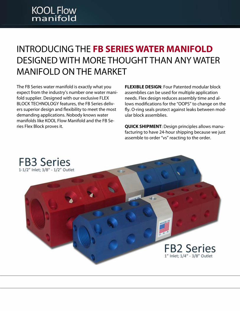
INTRODUCING THE FB SERIES WATER MANIFOLD DESIGNED WITH MORE THOUGHT THAN ANY WATER MANIFOLD ON THE MARKET The FB Series water manifold is exactly what you expect from the industry’s number one water mani-fold supplier. Designed with our exclusive FLEX BLOCK TECHNOLOGY features, the FB Series deliv-ers superior design and flexibility to meet the most demanding applications. Nobody knows water manifolds like KOOL Flow Manifold and the FB Se-ries Flex Block proves it.
FLEXIBLE DESIGN: Four Patented modular block assemblies can be used for multiple application needs. Flex design reduces assembly time and al-lows modifications for the “OOPS” to change on the fly. O-ring seals protect against leaks between mod-ular block assemblies. QUICK SHIPMENT: Design principles allows manu-facturing to have 24-hour shipping because we just assemble to order “vs” reacting to the order.

Select the Product you need! Choose from: Three Flex Block Manifold Styles, Four Port Sizes and Two Manifold Sizes.
FB Series Manifold
Port-to-Port (PP) Port-to-Blank (PB) Port-to-Divide (PD)
Are you limited for space? With a port-to-port configuration you can separate Hot & Cold and mount in different locations.
With a port-to-blank configuration you can eliminate the costly end plug and still mount the Hot & Cold in different locations.
Combine your cooling needs into one manifold. Separate Hot & Cold with a Mid-Block and mount in one easy location.
Features & Benefits Modular Construction Aluminum Material: Light Weight & Long Lasting Anodized for Corrosion Protection Various Port Size Options for Flexibility Pre-Drilled Mounting Holes Viton O-Rings & Tie Rods Included Stock Available for 24-Hour Shipment
Applications Injection Molding Resistant Welding Pneumatic Control Vacuum Forming Die Casting Extrusion Technology Water Distribution

FB2 Series Manifold
Specifications Block Size: 2.25” W x 2.25” H Material: 6061-T6, Anodized Mounting Hole Size: 1/4” SHCS Inlet Hole: 1” NPT Outlet Hole: 1/4” or 3/8” (5) Outlet Holes per Standard Block (3) Outlet Holes per 90 Degree Block
First Block Part Number Outlet Size Color Price
FB2‐FB‐1‐4‐R 1/4" Red $
FB2‐FB‐1‐4‐B 1/4" Blue $
FB2‐FB‐1‐6‐R 3/8" Red $
FB2‐FB‐1‐6‐B 3/8" Blue $
Mod Block Part Number Outlet Size Color Price
FB2‐MOD‐4‐R 1/4" Red $
FB2‐MOD‐4‐B 1/4" Blue $
FB2‐MOD‐6‐R 3/8" Red $
FB2‐MOD‐6‐B 3/8" Blue $
Last Block (Only used on Port‐to‐Port)
Part Number Outlet Size Color Price
FB2‐LB‐1‐4‐CL 1/4" Clear $
FB2‐LB‐1‐6‐CL 3/8" Clear $
Mid Block (Only used on Port‐To‐Divide)
Part Number Outlet Size Color Price
FB2‐MIDB‐1 n/a Clear $
End Block (Only used on Port‐to‐Blank)
Part Number Outlet Size Color Price
FB2‐EB‐CL n/a Clear $
90 Deg First Block
Part Number Outlet Size Color Price
FB2‐FB90‐1‐4‐R 1/4" Red $
FB2‐FB90‐1‐4‐B 1/4" Blue $
FB2‐FB90‐1‐6‐R 3/8" Red $
FB2‐FB90‐1‐6‐B 3/8" Blue $
90 Deg First Block 90 Deg Last Block
First Block Last Block
Mod Block End Block
*Prices include o-rings and hardware required for each block.
O-Ring Tie Rod
90 Deg Last Block
Part Number Outlet Size Color Price
FB2‐FB90‐1‐4‐CL 1/4" Clear $
FB2‐FB90‐1‐6‐CL 3/8" Clear $

FB2 Series Manifold
Assembly Part Numbers & Pricing
Port-to-Divide Port-to-Port Port-to-Blank
1/4" Outlet Assembly Number Price
FB2‐1‐4‐PD $
FB2‐2‐4‐PD $
FB2‐3‐4‐PD $
FB2‐4‐4‐PD $
FB2‐5‐4‐PD $
3/8" Outlet Assembly Number Price
FB2‐1‐6‐PD $
FB2‐2‐6‐PD $
FB2‐3‐6‐PD $
FB2‐4‐6‐PD $
FB2‐5‐6‐PD $
1/4" Outlet, Red Assembly Number Price
FB2‐1‐4‐R‐PP
FB2‐2‐4‐R‐PP $
FB2‐3‐4‐R‐PP $
FB2‐4‐4‐R‐PP $
FB2‐5‐4‐R‐PP $
1/4" Outlet, Blue Assembly Number Price
FB2‐1‐4‐B‐PP
FB2‐2‐4‐B‐PP $
FB2‐3‐4‐B‐PP $
FB2‐4‐4‐B‐PP $
FB2‐5‐4‐B‐PP $
3/8" Outlet, Red Assembly Number Price
FB2‐1‐6‐R‐PP
FB2‐2‐6‐R‐PP $
FB2‐3‐6‐R‐PP $
FB2‐4‐6‐R‐PP $
FB2‐5‐6‐R‐PP $
3/8" Outlet, Blue Assembly Number Price
FB2‐1‐6‐B‐PP
FB2‐2‐6‐B‐PP $
FB2‐3‐6‐B‐PP $
FB2‐4‐6‐B‐PP $
FB2‐5‐6‐B‐PP $
1/4" Outlet, Red Assembly Number Price
FB2‐1‐4‐R‐PB $
FB2‐2‐4‐R‐PB $
FB2‐3‐4‐R‐PB $
FB2‐4‐4‐R‐PB $
FB2‐5‐4‐R‐PB $
1/4" Outlet, Blue Assembly Number Price
FB2‐1‐4‐B‐PB $
FB2‐2‐4‐B‐PB $
FB2‐3‐4‐B‐PB $
FB2‐4‐4‐B‐PB $
FB2‐5‐4‐B‐PB $
3/8" Outlet, Red Assembly Number Price
FB2‐1‐6‐R‐PB $
FB2‐2‐6‐R‐PB $
FB2‐3‐6‐R‐PB $
FB2‐4‐6‐R‐PB $
FB2‐5‐6‐R‐PB $
3/8" Outlet, Blue Assembly Number Price
FB2‐1‐6‐B‐PB $
FB2‐2‐6‐B‐PB $
FB2‐3‐6‐B‐PB $
FB2‐4‐6‐B‐PB $
FB2‐5‐6‐B‐PB $
*Contact Kool Flow for OEM or large quantity Discounted pricing

FB2 90 Degree Series
Assembly Part Numbers & Pricing
Port-to-Divide Port-to-Port Port-to-Blank
1/4" Outlet
Assembly Number Price
FB290‐1‐4‐PD $
FB290‐2‐4‐PD $
FB290‐3‐4‐PD $
FB290‐4‐4‐PD $
FB290‐5‐4‐PD $
3/8" Outlet
Assembly Number Price
FB290‐1‐6‐PD $
FB290‐2‐6‐PD $
FB290‐3‐6‐PD $
FB290‐4‐6‐PD $
FB290‐5‐6‐PD $
1/4" Outlet, Red
Assembly Number Price
FB290‐1‐4‐R‐PP
FB290‐2‐4‐R‐PP $
FB290‐3‐4‐R‐PP $
FB290‐4‐4‐R‐PP $
FB290‐5‐4‐R‐PP $
1/4" Outlet, Blue
Assembly Number Price
FB290‐1‐4‐B‐PP
FB290‐2‐4‐B‐PP $
FB290‐3‐4‐B‐PP $
FB290‐4‐4‐B‐PP $
FB290‐5‐4‐B‐PP $
3/8" Outlet, Red
Assembly Number Price
FB290‐1‐6‐R‐PP
FB290‐2‐6‐R‐PP $
FB290‐3‐6‐R‐PP $
FB290‐4‐6‐R‐PP $
FB290‐5‐6‐R‐PP $
3/8" Outlet, Blue
Assembly Number Price
FB290‐1‐6‐B‐PP
FB290‐2‐6‐B‐PP $
FB290‐3‐6‐B‐PP $
FB290‐4‐6‐B‐PP $
FB290‐5‐6‐B‐PP $
1/4" Outlet, Red
Assembly Number Price
FB290‐1‐4‐R‐PB $
FB290‐2‐4‐R‐PB $
FB290‐3‐4‐R‐PB $
FB290‐4‐4‐R‐PB $
FB290‐5‐4‐R‐PB $
1/4" Outlet, Blue
Assembly Number Price
FB290‐1‐4‐B‐PB $
FB290‐2‐4‐B‐PB $
FB290‐3‐4‐B‐PB $
FB290‐4‐4‐B‐PB $
FB290‐5‐4‐B‐PB $
3/8" Outlet, Red
Assembly Number Price
FB290‐1‐6‐R‐PB $
FB290‐2‐6‐R‐PB $
FB290‐3‐6‐R‐PB $
FB290‐4‐6‐R‐PB $
FB290‐5‐6‐R‐PB $
3/8" Outlet, Blue
Assembly Number Price
FB290‐1‐6‐B‐PB $
FB290‐2‐6‐B‐PB $
FB290‐3‐6‐B‐PB $
FB290‐4‐6‐B‐PB $
FB290‐5‐6‐B‐PB $
*Contact Kool Flow for OEM or large quantity Discounted pricing

FB3 Series Manifold
First Block Part Number Outlet Size Color Price
FB3‐FB‐1.5‐6‐R 3/8" Red $
FB3‐FB‐1.5‐6‐B 3/8" Blue $
FB3‐FB‐1.5‐8‐R 1/2" Red $
FB3‐FB‐1.5‐8‐B 1/2" Blue $
Mod Block Part Number Outlet Size Color Price
FB3‐MOD‐6‐R 3/8" Red $
FB3‐MOD‐6‐B 3/8" Blue $
FB3‐MOD‐8‐R 1/2" Red $
FB3‐MOD‐8‐B 1/2" Blue $
Last Block (Only used on Port‐to‐Port)
Part Number Outlet Size Color Price
FB3‐LB‐1.5‐6‐CL 3/8" Clear $
FB3‐LB‐1.5‐8‐CL 1/2" Clear $
Mid Block (Only used on Port‐To‐Divide)
Part Number Outlet Size Color Price
FB3‐MIDB‐1 n/a Clear $
End Block (Only used on Port‐to‐Blank)
Part Number Outlet Size Color Price
FB3‐EB‐CL n/a Clear $
Specifications Block Size: 3.00” W x 3.00” H Material: 6061-T6, Anodized Mounting Hole Size: 3/8” SHCS Inlet Hole: 1-1/2” NPT Outlet Hole: 3/8” or 1/2” (5) Outlet Holes per Standard Block (3) Outlet Holes per 90 Degree Block
Visit our Web Site to configure a Part Number and Download CAD Files
90 Deg First Block
Part Number Outlet Size Color
FB3‐FB90‐1.5‐6‐R 3/8" Red $
FB3‐FB90‐1.5‐6‐B 3/8" Blue $
FB3‐FB90‐1.5‐8‐R 1/2" Red $
FB3‐FB90‐1.5‐8‐B 1/2" Blue $
90 Deg First Block 90 Deg Last Block
First Block Last Block
Mod Block End Block
*Prices include o-rings and hardware required for each block.
O-Ring Tie Rod
90 Deg Last Block
Part Number Outlet Size Color Price
FB3‐LB90‐1.5‐6‐CL 3/8" Clear $
FB3‐LB90‐1.5‐8‐CL 1/2" Clear $

FB3 Series Manifold
Assembly Part Numbers
3/8" Outlet Assembly Number
FB3‐1‐6‐PD
FB3‐2‐6‐PD
FB3‐3‐6‐PD
FB3‐4‐6‐PD
FB3‐5‐6‐PD
1/2" Outlet Assembly Number
FB3‐1‐8‐PD
FB3‐2‐8‐PD
FB3‐3‐8‐PD
FB3‐4‐8‐PD
FB3‐5‐8‐PD
3/8" Outlet, Red Assembly Number
FB3‐1‐6‐R‐PP
FB3‐2‐6‐R‐PP
FB3‐3‐6‐R‐PP
FB3‐4‐6‐R‐PP
FB3‐5‐6‐R‐PP
3/8" Outlet, Blue Assembly Number
FB3‐1‐6‐B‐PP
FB3‐2‐6‐B‐PP
FB3‐3‐6‐B‐PP
FB3‐4‐6‐B‐PP
FB3‐5‐6‐B‐PP
1/2" Outlet, Red Assembly Number
FB3‐1‐8‐R‐PP
FB3‐2‐8‐R‐PP
FB3‐3‐8‐R‐PP
FB3‐4‐8‐R‐PP
FB3‐5‐8‐R‐PP
1/2" Outlet, Blue Assembly Number Price
FB3‐1‐8‐B‐PP
FB3‐2‐8‐B‐PP $
FB3‐3‐8‐B‐PP $
FB3‐4‐8‐B‐PP $
FB3‐5‐8‐B‐PP $
3/8" Outlet, Red Assembly Number Price
FB3‐1‐6‐R‐PB $
FB3‐2‐6‐R‐PB $
FB3‐3‐6‐R‐PB $
FB3‐4‐6‐R‐PB $
FB3‐5‐6‐R‐PB $
3/8" Outlet, Blue Assembly Number Price
FB3‐1‐6‐B‐PB $
FB3‐2‐6‐B‐PB $
FB3‐3‐6‐B‐PB $
FB3‐4‐6‐B‐PB $
FB3‐5‐6‐B‐PB $
1/2" Outlet, Red Assembly Number Price
FB3‐1‐8‐R‐PB $
FB3‐2‐8‐R‐PB $
FB3‐3‐8‐R‐PB $
FB3‐4‐8‐R‐PB $
FB3‐5‐8‐R‐PB $
1/2" Outlet, Blue Assembly Number Price
FB3‐1‐8‐B‐PB $
FB3‐2‐8‐B‐PB $
FB3‐3‐8‐B‐PB $
FB3‐4‐8‐B‐PB $
FB3‐5‐8‐B‐PB $
*Contact Kool Flow for OEM or large quantity Discounted pricing
Port-to-Divide Port-to-Port Port-to-Blank

Quick, 24-Hour shipment available! Large inventory; we assemble to order.

FB3 90 Degree Series
Assembly Part Numbers & Pricing
3/8" Outlet
Assembly Number Price
FB390‐1‐6‐PD $
FB390‐2‐6‐PD $
FB390‐3‐6‐PD $
FB390‐4‐6‐PD $
FB390‐5‐6‐PD $
1/2" Outlet
Assembly Number Price
FB390‐1‐8‐PD $
FB390‐2‐8‐PD $
FB390‐3‐8‐PD $
FB390‐4‐8‐PD $
FB390‐5‐8‐PD $
3/8" Outlet, Red
Assembly Number Price
FB390‐1‐6‐R‐PP
FB390‐2‐6‐R‐PP $
FB390‐3‐6‐R‐PP $
FB390‐4‐6‐R‐PP $
FB390‐5‐6‐R‐PP $
3/8" Outlet, Blue
Assembly Number Price
FB390‐1‐6‐B‐PP
FB390‐2‐6‐B‐PP $
FB390‐3‐6‐B‐PP $
FB390‐4‐6‐B‐PP $
FB390‐5‐6‐B‐PP $
1/2" Outlet, Red
Assembly Number Price
FB390‐1‐8‐R‐PP
FB390‐2‐8‐R‐PP $
FB390‐3‐8‐R‐PP $
FB390‐4‐8‐R‐PP $
FB390‐5‐8‐R‐PP $
1/2" Outlet, Blue
Assembly Number Price
FB390‐1‐8‐B‐PP
FB390‐2‐8‐B‐PP $
FB390‐3‐8‐B‐PP $
FB390‐4‐8‐B‐PP $
FB390‐5‐8‐B‐PP $
3/8" Outlet, Red
Assembly Number Price
FB390‐1‐6‐R‐PB $
FB390‐2‐6‐R‐PB $
FB390‐3‐6‐R‐PB $
FB390‐4‐6‐R‐PB $
FB390‐5‐6‐R‐PB $
3/8" Outlet, Blue
Assembly Number Price
FB390‐1‐6‐B‐PB $
FB390‐2‐6‐B‐PB $
FB390‐3‐6‐B‐PB $
FB390‐4‐6‐B‐PB $
FB390‐5‐6‐B‐PB $
1/2" Outlet, Red
Assembly Number Price
FB390‐1‐8‐R‐PB $
FB390‐2‐8‐R‐PB $
FB390‐3‐8‐R‐PB $
FB390‐4‐8‐R‐PB $
FB390‐5‐8‐R‐PB $
1/2" Outlet, Blue
Assembly Number Price
FB390‐1‐8‐B‐PB $
FB390‐2‐8‐B‐PB $
FB390‐3‐8‐B‐PB $
FB390‐4‐8‐B‐PB $
FB390‐5‐8‐B‐PB $
*Contact Kool Flow for OEM or large quantity Discounted pricing
Port-to-Divide Port-to-Port Port-to-Blank

FB2 Series Manifold
Assembly Layout Drawings
Port-to-Port (PP) Port-to-Blank (PB) Port-to-Divide (PD)
End Block (Red or Blue)
Mid Block (Clear)
Last Block (Red or Blue)
Specifications Block Size: 2.25” W x 2.25” H Material: 6061-T6, Anodized Mounting Hole Size: 1/4” SHCS Inlet Hole: 1” NPT Outlet Hole: 1/4” or 3/8” (5) Outlet Holes Standard per Block

FB290 Series Manifold
Assembly Layout Drawings
Port-to-Port (PP) Port-to-Blank (PB) Port-to-Divide (PD)
Specifications Block Size: 2.25” W x 2.25” H Material: 6061-T6, Anodized Mounting Hole Size: 1/4” SHCS Inlet Hole: 1” NPT Outlet Hole: 1/4” or 3/8” (5) Outlet Holes Standard per Block
End Block (Red or Blue)
Mid Block (Clear)
Last Block (Red or Blue)

FB3 Series Manifold
Assembly Layout Drawings
Port-to-Port (PP) Port-to-Blank (PB) Port-to-Divide (PD)
Specifications Block Size: 3.00” W x 3.00” H Material: 6061-T6, Anodized Mounting Hole Size: 3/8” SHCS Inlet Hole: 1-1/2” NPT Outlet Hole: 3/8” or 1/2” (5) Outlet Holes Standard per Block
End Block (Red or Blue)
Mid Block (Clear)
Last Block (Red or Blue)

FB390 Series Manifold
Assembly Layout Drawings
Port-to-Port (PP) Port-to-Blank (PB) Port-to-Divide (PD)
Specifications Block Size: 3.00” W x 3.00” H Material: 6061-T6, Anodized Mounting Hole Size: 3/8” SHCS Inlet Hole: 1-1/2” NPT Outlet Hole: 3/8” or 1/2” (5) Outlet Holes Standard per Block
End Block (Red or Blue)
Mid Block (Clear)
Last Block (Red or Blue)

800.968.6868
616.452.1469
Fax 616.452.1386
T-1819 Die Locator Plug
Cad data available for download at:
http://www.ajacs.com/mediafile/T1819.zip
***Use with Drill Bushing: 2-1/4 L 176-28