akd - tg drives · akd instructions ... write explicit message setup ..... 81. 8 december 2015 2....
TRANSCRIPT
AKD® Using AKD EtherNet/IP with RSLogix Manual
Edition May 2014, Working Draft Rev H
Valid for firmware version 1.14
Part Number 903-200009-00
Record of Document Revisions:

2 December 2015
Keep all manuals as a product component during the life span of the product.
Pass all manuals to future users and owners of the product.
Record of Document Revisions
Revision Remarks
A, 10/2011 Launch version
C, 06/2012 Changes made to AKD_Jog and AKD_Stop_Smooth instructions.
D, 08/2012 Minor changes made to phrasing and formatting.
E, 09/2013 Information on using Unicast connection added ➜ p. 17.
F, 12/2013 Controller Support (➜ p. 5) information updated. Data size of IL.FB corrected in Appendix
B: Parameter Listing (➜ p. 72).
EtherNet/IP is a registered trademark of ODVA, Inc. Windows is a registered trademark of Microsoft Corporation
Technical changes which improve the performance of the device may be made without prior notice.
Printed in the Czech republic. This document is the intellectual property of TG Drives, s.r.o.. All rights reserved. No part of this work may be reproduced in any form (by photocopying, microfilm or any other method) or stored, processed, copied or distributed by electronic means without the written permission of TG Drives, s.r.o.

December 2015 3
1. Table of Contents
1. Table of Contents ..................................................................................................................................... 3
2. Introduction ............................................................................................................................................... 8
2.1. Controller Support .............................................................................................................................. 8
2.2. Add-On Instructions ........................................................................................................................... 8
3. AKD Installation and Setup ..................................................................................................................... 9
4. Quick Start with the AKD Sample Project ............................................................................................ 10
4.1. Setup ................................................................................................................................................ 10
4.2. Running the Main Program Loop ..................................................................................................... 13
4.2.1. Test Sequence ......................................................................................................................... 14
4.3. Testing Individual Instructions ......................................................................................................... 15
5. Adding AKD Support to a New or Existing Project ............................................................................. 17
5.1. Adding the Ethernet IO Module for AKD Communication ............................................................... 17
5.2. Importing the AKD Add-On Instructions to a Project ....................................................................... 20
5.3. Using the AKD Add-On Instructions in a Project ............................................................................. 25
5.4. Reading and Writing Drive Parameters ........................................................................................... 29
5.4.1. Read Drive Parameter ............................................................................................................. 29
5.4.2. Write Drive Parameter ............................................................................................................. 31
5.4.3. Execute Drive Command Parameter ....................................................................................... 31
6. AKD Instructions .................................................................................................................................... 32
6.1. Motion Axis Drive Communication (AKD_Drive) ............................................................................. 32
6.1.1. Description ............................................................................................................................... 32
6.1.2. Operands ................................................................................................................................. 32
6.1.3. AKD_DRIVE Structure ............................................................................................................. 32
6.1.4. Execution ................................................................................................................................. 32
6.1.5. Changes to Axis Status Bits .................................................................................................... 33
6.2. Motion Axis On (AKD_Enable) ........................................................................................................ 34
6.2.1. Description ............................................................................................................................... 34
6.2.2. Operands ................................................................................................................................. 34
6.2.3. AKD_ENABLE Structure .......................................................................................................... 34
6.2.4. Execution ................................................................................................................................. 34
6.2.5. Changes to Axis Status Bits .................................................................................................... 34
6.3. Motion Axis Off (AKD_Disable)........................................................................................................ 35
6.3.1. Description ............................................................................................................................... 35
6.3.2. Operands ................................................................................................................................. 35
6.3.3. AKD_DISABLE Structure ......................................................................................................... 35
6.3.4. Execution ................................................................................................................................. 35
6.3.5. Changes to Axis Status Bits .................................................................................................... 35

4 December 2015
6.4. Motion Axis Home (AKD_Home) ..................................................................................................... 36
6.4.1. Description ............................................................................................................................... 36
6.4.2. Operands ................................................................................................................................. 36
6.4.3. AKD_HOME Structure ............................................................................................................. 36
6.4.4. Execution ................................................................................................................................. 36
6.4.5. Changes to Axis Status Bits .................................................................................................... 37
6.5. Motion Axis Jog (AKD_Jog) ............................................................................................................. 37
6.5.1. Description ............................................................................................................................... 37
6.5.2. Operands ................................................................................................................................. 37
6.5.3. AKD_JOG Structure ................................................................................................................ 37
6.5.4. Programming Guidelines ......................................................................................................... 38
6.5.5. Execution ................................................................................................................................. 38
6.5.6. Changes to Axis Status Bits .................................................................................................... 38
6.6. Motion Axis Move (AKD_Move) ....................................................................................................... 39
6.6.1. Description ............................................................................................................................... 39
6.6.2. Operands ................................................................................................................................. 39
6.6.3. AKD_MOVE Structure ............................................................................................................. 39
6.6.4. Programming Guidelines ......................................................................................................... 40
6.6.5. Choosing a Move Type ............................................................................................................ 40
6.6.6. Execution ................................................................................................................................. 40
6.6.7. Changes to Axis Status Bits .................................................................................................... 40
6.7. Motion Axis Set Home Mode (AKD_Set_Home_Mode) .................................................................. 41
6.7.1. Description ............................................................................................................................... 41
6.7.2. Operands ................................................................................................................................. 41
6.7.3. AKD_SET_HOME_MODE Structure ....................................................................................... 41
6.7.4. Homing Modes ......................................................................................................................... 42
6.7.5. Execution ................................................................................................................................. 42
6.7.6. Changes to Axis Status Bit ...................................................................................................... 42
6.8. Motion Axis Set Acceleration (AKD_Set_Accel) .............................................................................. 43
6.8.1. Description ............................................................................................................................... 43
6.8.2. Operands ................................................................................................................................. 43
6.8.3. AKD_SET_ACCEL Structure ................................................................................................... 43
6.8.4. Execution ................................................................................................................................. 43
6.8.5. Changes to Axis Status Bits .................................................................................................... 43
6.9. Motion Axis Set Deceleration (AKD_Set_Decel) ............................................................................. 44
6.9.1. Description ............................................................................................................................... 44
6.9.2. Operands ................................................................................................................................. 44
6.9.3. AKD_SET_DECEL Structure ................................................................................................... 44
6.9.4. Execution ................................................................................................................................. 44
6.9.5. Changes to Axis Bits ................................................................................................................ 44
6.10. Motion Axis Set Mode (AKD_Set_Mode) ........................................................................................ 45

December 2015 5
6.10.1. Description ............................................................................................................................... 45
6.10.2. Operands ................................................................................................................................. 45
6.10.3. AKD_SET_MODE Structure .................................................................................................... 45
6.10.4. Operation Modes ..................................................................................................................... 45
6.10.5. Execution ................................................................................................................................. 46
6.10.6. Changes to Axis Status Bits .................................................................................................... 46
6.11. Motion Axis Set Position (AKD_Set_Position) ................................................................................. 47
6.11.1. Description ............................................................................................................................... 47
6.11.2. Operands ................................................................................................................................. 47
6.11.3. AKD_SET_POSITION Structure .............................................................................................. 47
6.11.4. Execution ................................................................................................................................. 48
6.11.5. Changes to Axis Status Bits .................................................................................................... 48
6.12. Motion Axis Set Velocity (AKD_Set_Velocity) ................................................................................. 49
6.12.1. Description ............................................................................................................................... 49
6.12.2. Operands ................................................................................................................................. 49
6.12.3. AKD_SET_VELOCITY Structure ............................................................................................. 49
6.12.4. Execution ................................................................................................................................. 50
6.12.5. Changes to Axis Status Bits .................................................................................................... 50
6.13. Motion Axis Shutdown (AKD_Shutdown) ........................................................................................ 51
6.13.1. Operands ................................................................................................................................. 51
6.13.2. AKD_SHUTDOWN Structure ................................................................................................... 51
6.13.3. Execution ................................................................................................................................. 52
6.13.4. Changes to Axis Status Bits .................................................................................................... 52
6.14. Motion Axis Shutdown Reset (AKD_Shutdown_Reset) .................................................................. 53
6.14.1. Description ............................................................................................................................... 53
6.14.2. Operands ................................................................................................................................. 53
6.14.3. AKD_SHUTDOWN_RESET Structure .................................................................................... 53
6.14.4. Execution ................................................................................................................................. 53
6.14.5. Changes to Axis Status Bits .................................................................................................... 53
6.15. Motion Axis Smooth Stop (AKD_Stop_Smooth).............................................................................. 54
6.15.1. Description ............................................................................................................................... 54
6.15.2. Operands ................................................................................................................................. 54
6.15.3. AKD_STOP_SMOOTH Structure ............................................................................................ 54
6.15.4. Execution ................................................................................................................................. 54
6.15.5. Changes to Axis Status Bits .................................................................................................... 54
6.16. Motion Axis Get Position Controller Attribute (AKD_Get_Attribute) ................................................ 55
6.16.1. Description ............................................................................................................................... 55
6.16.2. Operands ................................................................................................................................. 55
6.16.3. AKD_GET_ATTRIBUTE Structure .......................................................................................... 55
6.16.4. Execution ................................................................................................................................. 55
6.16.5. Changes to Axis Status Bits .................................................................................................... 55

6 December 2015
6.17. Motion Axis Get Parameter (AKD_Get_Parameter) ........................................................................ 56
6.17.1. Description ............................................................................................................................... 56
6.17.2. Operands ................................................................................................................................. 56
6.17.3. AKD_GET_PARAMETER Structure ........................................................................................ 56
6.17.4. Execution ................................................................................................................................. 56
6.17.5. Changes to Axis Status Bits .................................................................................................... 56
6.18. Motion Axis Set Position Controller Attribute (AKD_Set_Attribute) ................................................. 57
6.18.1. Description ............................................................................................................................... 57
6.18.2. Operands ................................................................................................................................. 57
6.18.3. AKD_SET_ATTRIBUTE Structure ........................................................................................... 57
6.18.4. Execution ................................................................................................................................. 57
6.18.5. Changes to Axis Status Bits .................................................................................................... 57
6.19. Motion Axis Set Parameter (AKD_Set_Parameter) ......................................................................... 58
6.19.1. Description ............................................................................................................................... 58
6.19.2. Operands ................................................................................................................................. 58
6.19.3. AKD_SET_PARAMETER Structure ........................................................................................ 58
6.19.4. Execution ................................................................................................................................. 58
6.19.5. Changes to Axis Status Bits .................................................................................................... 58
6.20. Motion Axis Set Units (AKD_Set_Units) .......................................................................................... 59
6.20.1. Description ............................................................................................................................... 59
6.20.2. Operands ................................................................................................................................. 59
6.20.3. AKD_SET_UNITS Structure .................................................................................................... 59
6.20.4. Execution ................................................................................................................................. 59
6.20.5. Changes to Axis Status Bits .................................................................................................... 59
6.21. Motion Axis Torque (AKD_Torque_Move) ....................................................................................... 60
6.21.1. Description ............................................................................................................................... 60
6.21.2. Operands ................................................................................................................................. 60
6.21.3. AKD_TORQUE_MOVE Structure ............................................................................................ 60
6.21.4. Programming Guidelines ......................................................................................................... 60
6.21.5. Execution ................................................................................................................................. 60
6.21.6. Changes to Axis Status Bits .................................................................................................... 60
6.22. Fault Reset (AKD_Fault_Reset) ...................................................................................................... 61
6.22.1. Description ............................................................................................................................... 61
6.22.2. Operands ................................................................................................................................. 61
6.22.3. AKD_FAULT_RESET Structure .............................................................................................. 61
6.22.4. Programming Guidelines ......................................................................................................... 61
6.22.5. Execution ................................................................................................................................. 61
6.22.6. Changes to Axis Status Bits .................................................................................................... 61
7. Troubleshooting ..................................................................................................................................... 62
7.1. Introduction ...................................................................................................................................... 62

December 2015 7
7.2. .ER (Error) bit ................................................................................................................................... 62
7.2.1. Unconfigured Axis was Specified ............................................................................................ 62
7.2.2. Communication Timeout .......................................................................................................... 62
7.2.3. Operand value out of range ..................................................................................................... 63
7.3. AKD Fault......................................................................................................................................... 63
7.3.1. Fieldbus Fault – F702 .............................................................................................................. 63
8. Appendix A: Supported EtherNet/IP Objects and Attributes ............................................................. 64
8.1. Position Controller Object 0x25 ....................................................................................................... 64
9. Appendix B: Parameter Listing ............................................................................................................. 65
10. Appendix C: RSLogix 500 ...................................................................................................................... 78
10.1. PLC & Drive TCP/IP Settings .......................................................................................................... 78
10.2. Read Explicit Message Setup .......................................................................................................... 79
10.3. Write Explicit Message Setup .......................................................................................................... 81

8 December 2015
2. Introduction
This manual provides an easy start guide for using AKD with RSLogix5000, an overview on how to import
and configure the AKD Add-On instructions using RSLogix5000 version 16 or later, as well as a reference to
the Add-On instructions.
RSLogix sample projects and add-on instructions, which demonstrate an EtherNet/IP network with a
Compact Logix controller and the AKD are available on demand.
The sample projects are based on an L32E CompactLogix controller, which can easily be changed to
another controller which supports RSLogix5000.
This document assumes that the reader has a basic knowledge of EtherNet/IP protocols, AKD drives, and
Rockwell RSLogix5000.
2.1. Controller Support
The Add-On Instructions described in this manual are only supported on CompactLogix and ControlLogix
controllers. A sample project is available on demand.
MicroLogix 1400 controllers are supported but the Add-On Instructions provided with RSLogix5000 cannot
be used. Only explicit messaging is supported.
MicroLogix 1100 and SLC500 are not supported.
2.2. Add-On Instructions
The AKD Add-On Instructions are RSLogix instructions that define AKD drives and axis configurations.
These instructions are made to be imported into an RSLogix5000 project. Once defined in a project, they
function just as a native RSLogix instruction. The add-on instructions encapsulate the most commonly used
logic for AKD axes. They provide easily reusable tools to operate drives and axes, promoting consistency
across different projects.
Note that the native MSG instruction is used in RSLogix for sending Explicit Messages.
A set of Add-On instructions are provided for easy creation of AKD programs with RSLogix. The instructions
are written to mirror the native instructions, leveraging existing knowledge of the software. They provide easy
control of IO Assembly messages.
Add-On Instructions include:
AKD_Disable
AKD_Drive
AKD_Enable
AKD_Fault_Reset
AKD_Get_Attribute
AKD_Get_Parameter
AKD_Home
AKD_Jog
AKD_Move
AKD_Set_Accel
AKD_Set_Attribute
AKD_Set_Decel
AKD_Set_Home_Mode
AKD_Set_Mode
AKD_Set_Parameter
AKD_Set_Position
AKD_Set_Units
AKD_Set_Velocity
AKD_Shutdown
AKD_Shutdown_Reset
AKD_Stop_Smooth
AKD_Torque_Move

December 2015 9
3. AKD Installation and Setup
See the following manuals for installation and setup of an AKD drive:
AKD Quick Start (also available in hard copy). This guide provides instructions for initial
drive setup and connection to a network.
AKD Installation Manual (also available in hard copy). This manual provides instructions
for installation and drive setup.
AKD Parameter and Command Reference Guide. This guide provides documentation
for the parameters and commands used to program the AKD.
AKDEtherNet/IP Communication Guide. This guide describes the communication profile
and use of EtherNet/IP with the AKD.

10 December 2015
4. Quick Start with the AKD Sample Project
The sample project AKD_Sample_Project.ACD demonstrates the correct setup of an axis and runs a
program loop which demonstrates point-to-point position moves, motion tasking control, and jogging.
This project can help you to learn:
how to enable the drive
how to write/read a parameter via the acyclic channel
how the cyclic data exchange is done
how to command motion in position or velocity mode
how to clear faults
how to load and execute motion task sequences
4.1. Setup
1. Start RSLogix5000 and open the file AKD_Sample_Project.ACD in the installer directory.
2. You will most likely need to update the controller properties to match your specific installation. Right click
on the controller (“AKD_Controller”) at the top of the tree and select “Properties” (Figure 4-1: Opening
Controller Properties).
1. Note that you can also use the Controller Properties button located above the tree
Figure 4-1: Opening Controller Properties
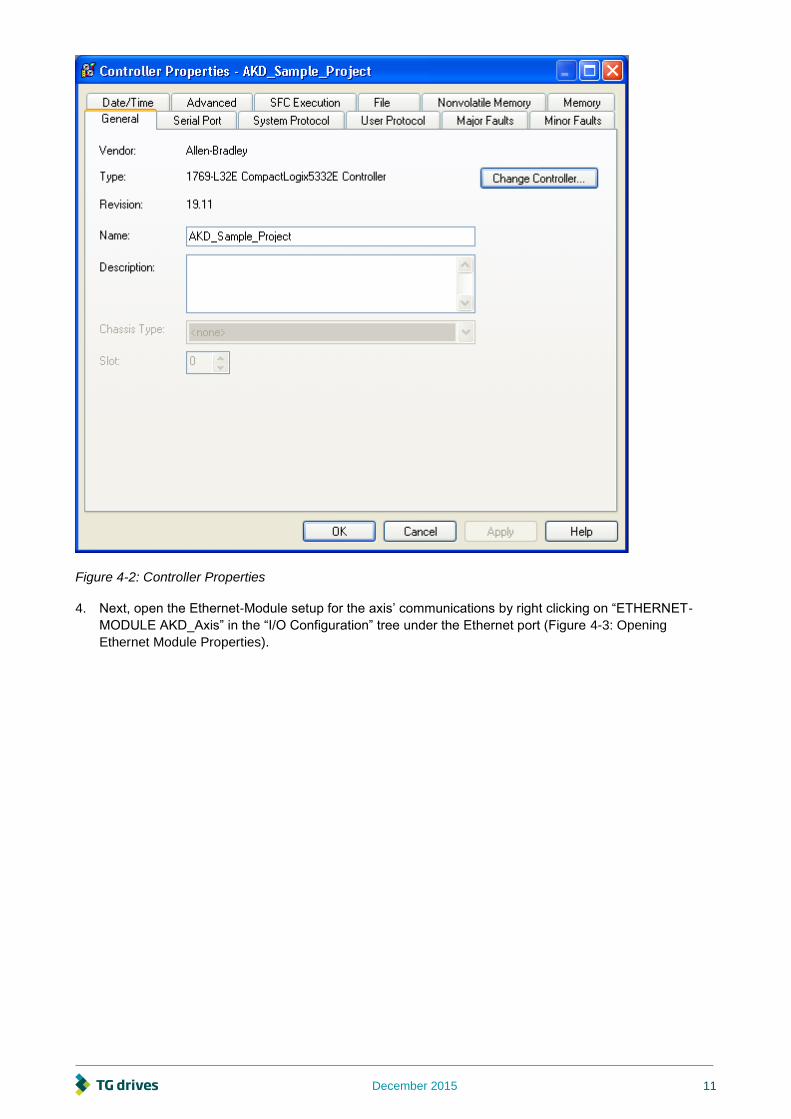
3. Update any controller properties in order for the controller to match your specific hardware setup, most
notably any communication settings and/or the controller type, and then close the controller properties
window (Figure 4-2: Controller Properties).
December 2015 11
Figure 4-2: Controller Properties
4. Next, open the Ethernet-Module setup for the axis’ communications by right clicking on “ETHERNET-
MODULE AKD_Axis” in the “I/O Configuration” tree under the Ethernet port (Figure 4-3: Opening
Ethernet Module Properties).

12 December 2015
Figure 4-3: Opening Ethernet Module Properties
5. Note the IP Address configured for the drive in this module. As changing the address would cause the
MSG instruction blocks to no longer reference a valid address, this value should not be changed in the
module. Instead, configure your drive to match the project settings.

December 2015 13
Figure 4-4: Ethernet Module Properties
6. Once you have updated all of the configuration settings to match your specific hardware setup, you can
download the program to the controller and use the project to test any of the axis commands.
4.2. Running the Main Program Loop
The top level of the program is in the subroutine “Tasks > MainTask > MainProgram > MainRoutine.”
The sample program has two modes. When the tag Active_Command.Control_Mode=0, the program is
setup to execute a continuous demo loop. The second mode (tag value=1) is used for testing individual
commands, and is described in the next section of the manual.
To begin executing the continuous demo loop, set the tag Active_Command.Control_Mode=0, then set the
tag Main_Sequence_Step = 1.
Figure 4-5: Main Program of AKD Sample Project
14 December 2015
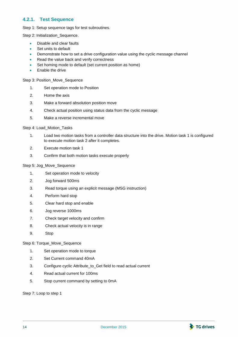
4.2.1. Test Sequence
Step 1: Setup sequence tags for test subroutines.
Step 2: Initialization_Sequence.
Disable and clear faults
Set units to default
Demonstrate how to set a drive configuration value using the cyclic message channel
Read the value back and verify correctness
Set homing mode to default (set current position as home)
Enable the drive
Step 3: Position_Move_Sequence
1. Set operation mode to Position
2. Home the axis
3. Make a forward absolution position move
4. Check actual position using status data from the cyclic message
5. Make a reverse incremental move
Step 4: Load_Motion_Tasks
1. Load two motion tasks from a controller data structure into the drive. Motion task 1 is configured
to execute motion task 2 after it completes.
2. Execute motion task 1
3. Confirm that both motion tasks execute properly
Step 5: Jog_Move_Sequence
1. Set operation mode to velocity
2. Jog forward 500ms
3. Read torque using an explicit message (MSG instruction)
4. Perform hard stop
5. Clear hard stop and enable
6. Jog reverse 1000ms
7. Check target velocity and confirm
8. Check actual velocity is in range
9. Stop
Step 6: Torque_Move_Sequence
1. Set operation mode to torque
2. Set Current command 40mA
3. Configure cyclic Attribute_to_Get field to read actual current
4. Read actual current for 100ms
5. Stop current command by setting to 0mA
Step 7: Loop to step 1

December 2015 15
4.3. Testing Individual Instructions
All of the instruction calls are in the TG Drives_AOIs subroutine, which you can open from “Tasks > Main
Task > MainProgram > TG Drives_AIOs” (Figure 4-6: AKD Instruction Subroutine).
To test individual instructions, set the tag Active_Command.Control_Mode=1 so that the TG Drives_AOIs
subroutine will be called from MainRoutine.
Make sure to review “AKD Instructions” below for a complete understanding of the instructions and their
operation before executing any instructions in the example program.
Figure 4-6: AKD Instruction Subroutine
All of the instructions have their own individual trigger coils. To call an instruction, toggle its trigger coil
(Figure 4-7: Toggling a Trigger Coil)

16 December 2015
Figure 4-7: Toggling a Trigger Coil
Only one AKD add-on instruction can be enabled at a time. The add-on instructions write to the same data
structure to set control bits and command motion. Trying to call two add-on instructions at one time would
create a conflict for the control of the communication channel. Please keep this in mind when executing
these instructions.

December 2015 17
5. Adding AKD Support to a New or Existing Project
5.1. Adding the Ethernet IO Module for AKD Communication
These basic instructions can be used for any Rockwell PLC that uses RSLogix5000 and supports
EtherNet/IP.
1. Start RSLogix5000 and open the project with which you want to use the AKD drive.
2. Right click on the Ethernet port in the I/O Configuration and select “New Module…” (Figure 5-1:
Adding New Module)
Figure 5-1: Adding New Module
3. Select “ETHERNET-MODULE” under “Communications” and click OK (Figure 5-2: Selecting
Module Type)

18 December 2015
Figure 5-2: Selecting Module Type
4. Enter the settings for the new module as described below, make sure the “Open Module
Properties” checkbox is checked, and click OK (Table 4 1: Module Setting Values & Figure 5-3:
Entering Module Settings)
Field Value
Name AKD_Drive
Description Text description for drive
Comm Format Data--SINT
IP Address Ethernet IP address for drive
Input Assembly Instance 102
Input Size 64
Output Assembly Instance 101
Output Size 64
Configuration Assembly Instance 100
Configuration Size 0
Table 5-1: Module Setting Values

December 2015 19
Figure 5-3: Entering Module Settings
5. The “New Module” window now appears as a “Module Properties: LocalENB” window with the
Connection tab selected. Set the “Requested Packet Interval (RPI)” value to 20.0 ms (this can be
reduced to 10.0ms when not using Workbench in combination with EtherNet/IP). If using
firmware version 1.8 or higher, check the box “Use Unicast Connection over EtherNet/IP" if the
option is available. For older versions of firmware leave this box unchecked. Click OK. (Figure 5-
4: Setting Module RPI).
Figure 5-4: Setting Module RPI
6. The drive should now be configured and will show up under the Ethernet Port (Figure 5-5:
Module Successfully Added to Project)

20 December 2015
Figure 5-5: Module Successfully Added to Project
7. Make sure that the Ethernet port for your controller is setup with a compatible IP address on the
same subnet as the AKD drive IP address. This can be configured by right-clicking on 1769-
L23E-QB1 Ethernet Port Local and selecting properties. See your controller user manual for
more information.
5.2. Importing the AKD Add-On Instructions to a Project
1. The User Defined Data Types must be imported before the Add-On Instructions.
2. Right click the “User-Defined” folder under “Data Types” and select “Import Data Type…” (Figure 5-
6: Importing Data Types)

December 2015 21
Figure 5-6: Importing Data Types
3. Browse to the location of the AKD User Defined Data Type library and select the desired User
Defined Data Type then click “Import…” (Figure 5-7: Selecting a UDT)
4. Import the data types in the order shown in Table 5-2: UDT Import Order.

22 December 2015
Figure 5-7: Selecting a UDT
Order File Descrption
1 AKD_Control_UDT.L5X Control message for sending to axis
2 AKD_Status_UDT.L5X Status message for updating from axis
3 AKD_Axis_UDT.L5X Axis definition
4 Motion_Task_UDT.L5X Motion Task data table structure
Table 5-2: UDT Import Order
5. Click OK on the import configuration dialog, if one appears. Repeat for all files in “Table 5-2: UDT
Import Order” to import all of the needed data types
6. The data types should now show up under the “Data Types > User-Defined” folder (Figure 5-8: Data
Types Successfully Imported)

December 2015 23
Figure 5-8: Data Types Successfully Imported
7. Next, to import the add-on instructions, right click on the “Add-On Instructions” folder and select
“Import Add-On Instruction…” (Figure 5-9: Importing Add-On Instructions)
Figure 5-9: Importing Add-On Instructions
8. Browse to the location of the AKD Add On Instruction library and select the desired AOI then click
“Import…” (Figure 5-10: Selecting an AOI)
9. For complete functionality, import all of the files listed in “Table 5-3: All Add On Instructions”

24 December 2015
Figure 5-10: Selecting an AIO
File Description
AKD_Disable_AOI.L5X Motion Axis Off
AKD_Drive_AOI.L5X Drive Communication
AKD_Enable_AOI.L5X Motion Axis On
AKD_Fault_Reset_A OI.L5X
Motion Axis Fault Reset
AKD_Get_Attribute_AOI.L5X Get Axis Attribute
AKD_Get_Parameter_AOI.L5X Get Axis Parameter
AKD_Home_AOI.L5X Motion Axis Home
AKD_Jog_AOI.L5X Motion Axis Jog
AKD_Move_AOI.L5X Motion Axis Move
AKD_Set_Accel_AOI.L5X Motion Axis Set Acceleration
AKD_Set_Attribute_AOI.L5X Set Axis Attribute
AKD_Set_Decel_AOI.L5X Motion Axis Set Deceleration
AKD_Set_Home_Mode_AOI.L5X Motion Axis Set Home Mode
AKD_Set_Mode_AOI.L5X Motion Axis Set Mode
AKD_Set_Parameter_AOI.L5X Set Axis Parameter
AKD_Set_Position_AOI.L5X Motion Axis Set Position
AKD_Set_Units_AOI.L5X Motion Axis Set Units
AKD_Set_Velocity_AOI.L5X Motion Axis Set Velocity
AKD_Shutdown_AOI.L5X Motion Axis Shutdown
AKD_Shutdown_Reset_AOI.L5X Motion Axis Shutdown Reset
AKD_Stop_Smooth_AOI.L5X Motion Axis Smooth Stop
AKD_Torque_Move_AOI.L5X Motion Axis Torque
Table 5-3: All Add On Instructions

December 2015 25
10. Click OK on the import configuration dialog, if any appear. Repeat for all files in “Table 5-3: All Add
On Instructions” to import all of the needed instructions for full functionality
11. The instructions should now show up under the “Add-On Instructions” folder (Figure 5-11: AOI’s
Successfully Imported)
Figure 5-11: AOI's Successfully Imported
5.3. Using the AKD Add-On Instructions in a Project
In any project where you want to use the AKD Add-On instructions, you will need to include one instance of
the Drive Communication logic for each axis (AKD_Drive instruction).
26 December 2015
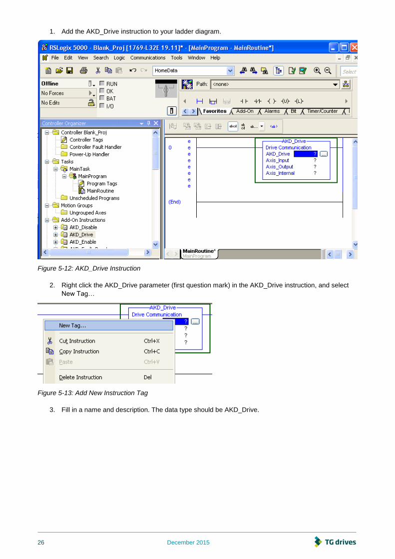
1. Add the AKD_Drive instruction to your ladder diagram.
Figure 5-12: AKD_Drive Instruction
2. Right click the AKD_Drive parameter (first question mark) in the AKD_Drive instruction, and select
New Tag…
Figure 5-13: Add New Instruction Tag
3. Fill in a name and description. The data type should be AKD_Drive.

December 2015 27
Figure 5-14: Adding Drive Communication
4. Click OK in the New Tag window to create your tag. It will now show up in your controller under
“Controller Tags”
Figure 5-15: Tag Added to Program
Figure 5-16: Adding Axis_Internal Parameter

28 December 2015
5. Set the Axis_Input parameter to the input data of the axis for which you are setting up
communication (Figure 5-18: Axis Communication Input). Double click the "?". A drop down box will
appear. Select the input data tag that corresponds to the “ETHERNET-MODULE” object you created
in the I/O Configuration of the project.
Figure 5-17: Axis Communication Input
6. Set the Axis_Output parameter to the output data of the axis for which you are setting up
communication (Figure 5-18: Axis Communication Output). Double click the "?". A drop down box
will appear. Select the output data tag that corresponds to the “ETHERNET-MODULE” object you
created in the I/O Configuration of the project.

December 2015 29
Figure 5-18: Axis Communication Output
7. Once you have configured the drive communication block, you should be able to use any of the other
AKD Add-On instructions as you would the native RSLogix instructions.
8. Repeat steps 2-4 to add a new tag to the Axis_Internal parameter of the instruction, with a data type
of AKD_Axis.
9. For more information on each instruction, see “Section 5: AKD Instructions” below.
5.4. Reading and Writing Drive Parameters
In addition to the Add-On instructions listed in this manual, almost all drive parameters can be read or set
through the use of a MSG instruction.
Appendix B provides a list of parameters which are available.
5.4.1. Read Drive Parameter
To read a parameter, create a MSG instruction with the following settings:
Field Value
Message Type CIP Generic
Service Type Parameter Read
Service Code e (Hex)
Class f (Hex)
Instance Parameter Instance from Appendix B
Attribute 1
Destination Create a tag to hold the value
Communication > Path Name of the ETHERNET-MODULE for the AKD axis. Use the Browse button.

30 December 2015
Figure 5-19: Message Configuration

December 2015 31
Figure 5-20: Message Configuration | Communication
5.4.2. Write Drive Parameter
To set a parameter, create a MSG instruction with the following settings:
Field Value
Message Type CIP Generic
Service Type Parameter Write
Service Code 10 (Hex)
Class f (Hex)
Instance Parameter Instance from Appendix B
Attribute 1
Source Element Create a tag to hold the value
Source Length Parameter size from Appendix B
Communication > Path Name of the ETHERNET-MODULE for the AKD axis. Use the Browse button.
5.4.3. Execute Drive Command Parameter
Some drive parameters are actually commands which do not take a value, but execute a drive function such
as HOME.MOVE or DRV.CLEARFAULTS. To execute a command, create a MSG instruction to write to the
command:
Field Value
Message Type CIP Generic
Service Type Parameter Write
Service Code 10 (Hex)
Class f (Hex)
Instance Parameter Instance from Appendix B
Attribute 1
Source Element Create a tag to hold the value. Any actual value may be used - it is ignored.
Source Length 1 byte
Communication > Path Name of the ETHERNET-MODULE for the AKD axis. Use the Browse button.

32 December 2015
6. AKD Instructions
The AKD Add-On Instructions are RSLogix instructions that define AKD drives and axis configurations.
These instructions are made to be imported into an RSLogix5000 project. Once defined in a project, they
function just as a native RSLogix Motion instruction. The add-on instructions are written to mirror the native
instructions, leveraging existing knowledge of the software. The add-on instructions encapsulate the most
commonly used logic for AKD axes. They provide easily reusable tools to operate drives and axes,
promoting consistency across different projects. They provide easy control of I/O Assembly Messages. The
native MSG instruction is used in RSLogix for sending Explicit Messages.
1. Only one AKD add-on instruction can be enabled at a time in your project. The add-on
instructions write to the same data structure (the Command Assembly) to set control bits and
command motion. Trying to enable or execute two add-on instructions at one time would
create a conflict for the control of the communication channel. Keep this in mind when writing
programs that utilize these instructions.
6.1. Motion Axis Drive Communication (AKD_Drive)
6.1.1. Description
Use the motion axis drive communication (AKD_Drive) instruction to initiate communication for an axis. This
command is required for all other AKD commands to function properly.
6.1.2. Operands
Operand Type Format Description
AKD_Drive AKD_DRIVE Tag Control tag for this instruction.
Axis_Input AB:ETHERNET_MODULE_SINT_8Bytes:I:0 Tag Input memory space for axis.
Axis_Output AB:ETHERNET_MODULE_SINT_8Bytes:O:0 Tag Output memory space for axis.
Axis_Internal AKD_AXIS Tag The name of the axis to initialize. This tag is an input parameter for all AKD instructions.
6.1.3. AKD_DRIVE Structure
Mnemonic Data Type Description
.EnableIn BOOL The enable input bit indicates that the instruction is enabled. It remains set until the instruction completes and the rung-condition-in goes false.
.EnableOut BOOL The enable output bit is the output of the enable input bit.
6.1.4. Execution
Condition Ladder Diagram Action
Instruction execution Read response message and send command message to axis.

December 2015 33
6.1.5. Changes to Axis Status Bits
Bit Name Meaning
All All axis status bits are updated from drive.

34 December 2015
6.2. Motion Axis On (AKD_Enable)
6.2.1. Description
The Motion Axis On (AKD_Enable) instruction directly activates the drive and enables the configured servo
loops associated with a physical servo axis. It can be used anywhere in a program. Corresponds to the MSO
instruction in Rockwell drives.
The AKD_Enable instruction automatically enables the specified axis by activating the drive and by activating
the associated servo loop. The most common use of this instruction is to activate the servo loop for the
specified axis in its current position in preparation for commanding motion.
1. The AKD_Enable instruction execution may take multiple scans to execute because it requires
transmission of a message to the motion module and time for the drive output to stabilize and the
servo loop to activate. The Done (.DN) bit is not set immediately, but only after the axis is in the
Enabled state.
6.2.2. Operands
Operand Type Format Description
AKD_Enable AKD_ENABLE Tag Control tag for this instruction.
Axis AKD_AXIS Tag The name of the axis to enable.
6.2.3. AKD_ENABLE Structure
Mnemonic Data Type Description
.EnableIn BOOL The enable input bit indicates that the instruction is enabled. It remains set until the instruction completes and the rung-condition-in goes false.
.EnableOut BOOL The enable output bit is the output of the enable input bit.
.DN (Done) BOOL The done bit indicates when the enable instruction completes.
.ER (Error) BOOL The error bit indicates if the instruction detects an error.
.Axis AKD_AXIS The axis being enabled.
6.2.4. Execution
Condition Ladder Diagram Action
Prescan Initialize variables and clear timeout.
Rung-condition-in is false Initialize variables and clear timeout.
Instruction execution
Set enable bit in the command message to the drive if the drive does not have any faults. Then, set the done bit when the enabled response is returned. If the drive has a general fault or there is a communication timeout, set the error bit.
6.2.5. Changes to Axis Status Bits
Bit Name State Meaning
Enable True Axis is in Enabled state with the servo loop active.

December 2015 35
6.3. Motion Axis Off (AKD_Disable)
6.3.1. Description
The Motion Axis Off (AKD_Disable) instruction directly and immediately turns off drive output and disables
the servo loop on any physical servo axis. This places the axis in the Disabled state. The AKD_Disable
instruction also disables any motions that may be active at the time of execution. Corresponds to the MSF
instruction in Rockwell drives.
The AKD_Disable instruction requires no parameters - simply enter the desired axis. Use the Tag Editor to
create and configure a new axis.
You can use the AKD_Disable instruction to turn servo action OFF when you must move the axis by hand.
Since the position continues to be tracked even with the servo action Off, when the servo loop is turned On
again by the AKD_Enable instruction, the axis is again under closed-loop control, at the new position.
1. The AKD_Disable instruction execution may take multiple scans to execute because it requires
transmission of a message to the motion module and time for the drive output and servo loop to
be fully deactivated. The Done (.DN) bit is not set until this message has been successfully
transmitted and the axis transitions to the Disabled state.
6.3.2. Operands
Operand Type Format Description
AKD_Disable AKD_DISABLE Tag Control tag for this instruction.
Axis AKD_AXIS Tag The name of the axis to disable.
6.3.3. AKD_DISABLE Structure
Mnemonic Data Type Description
.EnableIn BOOL The enable input bit indicates that the instruction is enabled. It remains set until the instruction completes and the rung-condition-in goes false.
.EnableOut BOOL The enable output bit is the output of the enable input bit.
.DN (Done) BOOL The done bit indicates when the disable instruction completes.
.ER (Error) BOOL The error bit indicates if the instruction detects an error.
.Axis AKD_AXIS The axis being disabled.
6.3.4. Execution
Condition Ladder Diagram Action
Prescan Initialize variables and clear timeout.
Rung-condition-in is false Initialize variables and clear timeout.
Instruction execution Reset enable bit in the command message to the drive. Then, set the done bit when the disabled response is returned. If the drive has a general fault or there is a communication timeout, set the error bit.
6.3.5. Changes to Axis Status Bits
Bit Name State Meaning
Enable False Axis is in Disabled state with the servo loop active.

36 December 2015
6.4. Motion Axis Home (AKD_Home)
6.4.1. Description
The Motion Axis Home (AKD_Home) instruction triggers the axis to home using the currently configured
homing mode. See the AKD user manual for homing modes and setting instructions. This command triggers
the drive to start the procedure and monitors for the process to complete. Similar to the MAH instruction in
Rockwell drives.
Drive must be enabled in order to execute this instruction.
This is a transitional instruction:
In ladder diagram, toggle the rung-condition-in from cleared to set each time the
instruction should execute.
1. The AKD_HOME instruction execution may take multiple scans to execute because it requires
transmission of a message to the motion module and time for the drive to perform the homing
procedure.
6.4.2. Operands
Operand Type Format Description
AKD_Home AKD_HOME Tag Control tag for this instruction.
Axis AKD_AXIS Tag The name of the axis to home.
6.4.3. AKD_HOME Structure
Mnemonic Data Type Description
.EnableIn BOOL The enable input bit indicates that the instruction is enabled. It remains set until the instruction completes and the rung-condition-in goes false.
.EnableOut BOOL The enable output bit is the output of the enable input bit.
.DN (Done) BOOL The done bit indicates when the homing instruction completes.
.ER (Error) BOOL The error bit indicates if the instruction detects an error.
.IP (In Process) BOOL The in process bit is set when the command is enabled and remains true until the command completes or is terminated.
.PC (Process Complete)
BOOL The process complete bit is set when the homing command has successfully completed.
6.4.4. Execution
Condition Ladder Diagram Action
Prescan Initialize variables and clear timeout.
Rung-condition-in is false Initialize variables and clear timeout.
Instruction execution
Set the home command in the command message to the drive. Then, set the done bit when the command has initiated. The in process bit is set during execution and the process complete bit is set when the command has successfully completed. If the drive has a general fault or there is a communication timeout, set the error bit.

December 2015 37
6.4.5. Changes to Axis Status Bits
Bit Name State Meaning
Home_Level True Level of home input.
Profile_In_Progress True Profile move is in progress (this bit may be set and cleared during instruction execution).
6.5. Motion Axis Jog (AKD_Jog)
6.5.1. Description
Use the motion axis jog (AKD_Jog) instruction to move the axis at a constant speed until you tell it to stop.
Corresponds to the MAJ instruction in Rockwell drives.
Drive must be enabled and in velocity or position mode in order to execute this instruction. A general status
bit can be used to test if the jog motion is in progress.
6.5.2. Operands
Operand Type Format Description
AKD_Jog AKD_JOG Tag Control tag for this instruction.
Axis AKD_AXIS Tag The name of the axis to enable.
Accel DINT Immediate Acceleration rate of the axis.
Decel DINT Immediate Deceleration rate of the axis.
Direction DINT Immediate
For this jog direction: Enter:
Forward 1
Reverse 0
Speed DINT Immediate Speed to move the axis.
6.5.3. AKD_JOG Structure
Mnemonic Data Type Description
.EnableIn BOOL The enable input bit indicates that the instruction is enabled. It remains set until the instruction completes and the rung-condition-in goes false.
.EnableOut BOOL The enable output bit is the output of the enable input bit.
.DN (Done) BOOL The done bit indicates when the jog instruction is successfully initiated.
.ER (Error) BOOL The error bit indicates if the instruction detects an error.
38 December 2015
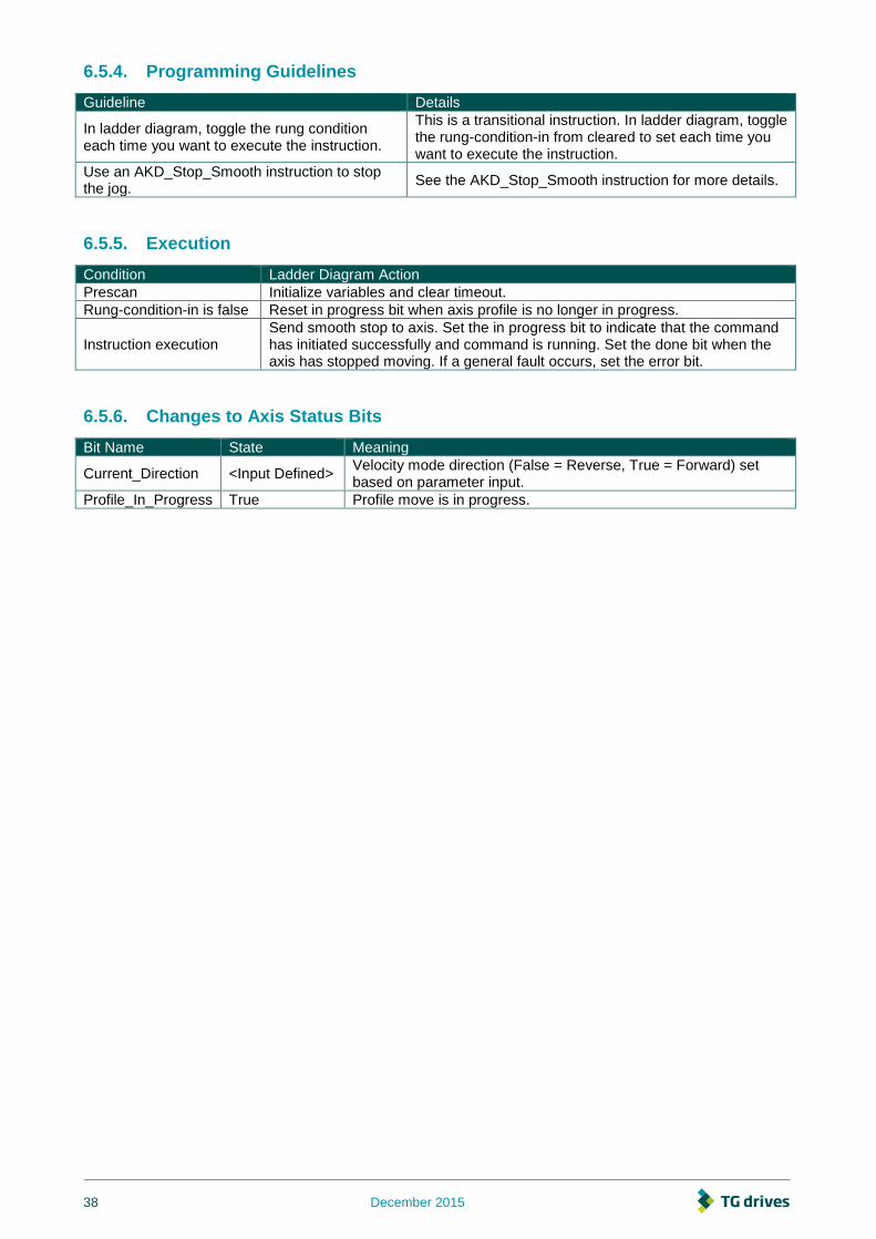
6.5.4. Programming Guidelines
Guideline Details
In ladder diagram, toggle the rung condition each time you want to execute the instruction.
This is a transitional instruction. In ladder diagram, toggle the rung-condition-in from cleared to set each time you want to execute the instruction.
Use an AKD_Stop_Smooth instruction to stop the jog.
See the AKD_Stop_Smooth instruction for more details.
6.5.5. Execution
Condition Ladder Diagram Action
Prescan Initialize variables and clear timeout.
Rung-condition-in is false Reset in progress bit when axis profile is no longer in progress.
Instruction execution Send smooth stop to axis. Set the in progress bit to indicate that the command has initiated successfully and command is running. Set the done bit when the axis has stopped moving. If a general fault occurs, set the error bit.
6.5.6. Changes to Axis Status Bits
Bit Name State Meaning
Current_Direction <Input Defined> Velocity mode direction (False = Reverse, True = Forward) set based on parameter input.
Profile_In_Progress True Profile move is in progress.

December 2015 39
6.6. Motion Axis Move (AKD_Move)
6.6.1. Description
Use the motion axis move (AKD_Move) instruction to move an axis to a specified relative or absolute
position. Corresponds to the MAM instruction in Rockwell drives.
Drive must be enabled, homed, and in position mode in order to execute this instruction.
6.6.2. Operands
Operand Type Format Description
AKD_Move AKD_MOVE Tag Control tag for this instruction.
Axis AKD_AXIS Tag The name of the axis to enable.
Move Type SINT Immediate
For this move mode Enter:
Absolute 0
Relative to Command Position 1
Accel DINT Immediate Acceleration rate of the axis.
Decel DINT Immediate Deceleration rate of the axis.
Speed DINT Immediate Speed to move the axis.
Position DINT Immediate Target position for move.
6.6.3. AKD_MOVE Structure
Mnemonic Data Type Description
.EnableIn BOOL The enable input bit indicates that the instruction is enabled. It remains set until the instruction completes and the rung-condition-in goes false.
.EnableOut BOOL The enable output bit is the output of the enable input bit.
.DN (Done) BOOL The done bit indicates when the move instruction is successfully initiated.
.ER (Error) BOOL The error bit indicates if the instruction detects an error.
.IP (In Process) BOOL The in process bit is set when the command is enabled and remains true until the move completes or is terminated.
.PC (Process Complete) BOOL The process complete bit is set when the command is complete.

40 December 2015
6.6.4. Programming Guidelines
Guideline Details
In ladder diagram, toggle the rung condition each time you want to execute the instruction.
This is a transitional instruction. In ladder diagram, toggle the rung-condition-in from cleared to set each time you want to execute the instruction.
Use the AKD_Move instruction to change one that is already in progress.
You can change the position target, speed, acceleration, or deceleration limits and the change will take place immediately. The axis will move to the updated position, possibly even changing direction, without stopping at the old end position.
6.6.5. Choosing a Move Type
See the AKD User Guide for more information on position move types.
6.6.6. Execution
Condition Ladder Diagram Action
Prescan Initialize variables and clear timeout.
Rung-condition-in is false
Reset in process bit when axis profile is no longer in progress. Set process complete bit when move command successfully completes.
Instruction execution
Reset done and error bits, then set accel, decel, speed, and position. Start move and set the done bit to indicate command started and set the in process bit to indicate that the command is running. If the motion stops, clear the in process bit. Set process complete bit when move command successfully completes. If a general fault occurs or there is a communication response timeout, set the error bit.
6.6.7. Changes to Axis Status Bits
Bit Name State Meaning
Profile_In_Progress True Profile move is in progress.
On_Target_Position True True once current position equals last target position.

December 2015 41
6.7. Motion Axis Set Home Mode (AKD_Set_Home_Mode)
6.7.1. Description
Use the motion axis set home mode (AKD_Set_Home_Mode) instruction to set the homing mode used by
the drive when the AKD_Home command is called.
1. The AKD_Set_Home_Mode instruction execution may take multiple scans to execute because it
requires transmission of a message to the motion module. The Done (.DN) bit is not set
immediately, but only after the home mode is set.
This is a transitional instruction:
In ladder diagram, toggle the rung-condition-in from cleared to set each time the
instruction should execute.
6.7.2. Operands
Operand Type Format Description
AKD_Set_ Home_Mode AKD_SET_ HOME_MODE Tag Control tag for this instruction.
Axis AKD_AXIS Tag The name of the axis to modify.
Mode SINT Immediate
For Mode Enter:
Current Position 0
Limit Input 1
Limit/Zero Angle 2
Limit/Index 3
Home Input 4
Home/Zero Angle 5
Home/Index 6
Zero Angle 7
Position Error 8
Position Error/Zero Angle 9
Position Error/Index 10
Index 11
Home OR Position Error 12
6.7.3. AKD_SET_HOME_MODE Structure
Mnemonic Data Type Description
.EnableIn BOOL The enable input bit indicates that the instruction is enabled. It remains set until the instruction completes and the rung-condition-in goes false.
.EnableOut BOOL The enable output bit is the output of the enable input bit.
.DN (Done) BOOL The done bit indicates when the mode is successfully set.
.ER (Error) BOOL The error bit indicates if the instruction detects an error.
42 December 2015
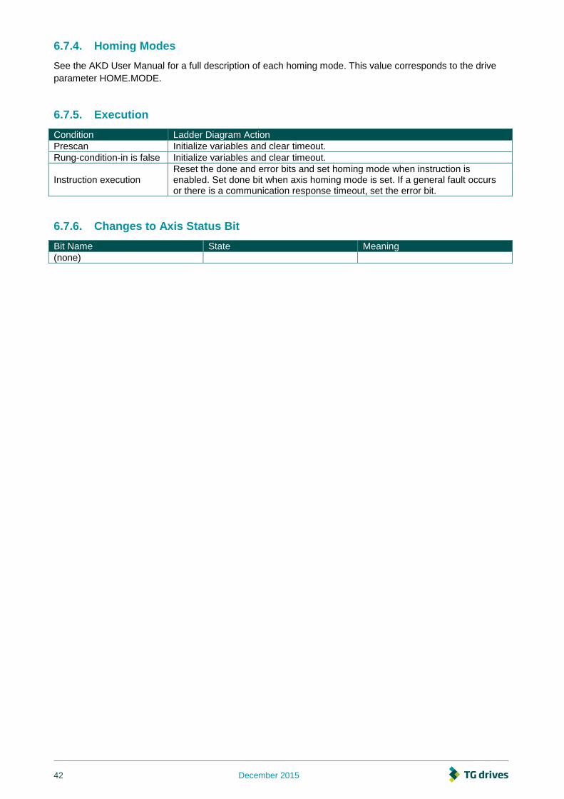
6.7.4. Homing Modes
See the AKD User Manual for a full description of each homing mode. This value corresponds to the drive
parameter HOME.MODE.
6.7.5. Execution
Condition Ladder Diagram Action
Prescan Initialize variables and clear timeout.
Rung-condition-in is false Initialize variables and clear timeout.
Instruction execution Reset the done and error bits and set homing mode when instruction is enabled. Set done bit when axis homing mode is set. If a general fault occurs or there is a communication response timeout, set the error bit.
6.7.6. Changes to Axis Status Bit
Bit Name State Meaning
(none)

December 2015 43
6.8. Motion Axis Set Acceleration (AKD_Set_Accel)
6.8.1. Description
Use the motion axis set acceleration (AKD_Set_Accel) instruction to set the axis acceleration parameter
used with axis moves.
1. The AKD_Set_Accel instruction execution may take multiple scans to execute because it
requires transmission of a message to the motion module. The Done (.DN) bit is not set
immediately, but only after the acceleration is set.
This is a transitional instruction. In ladder diagram, toggle the rung-condition-in from cleared to set each time
the instruction should execute.
6.8.2. Operands
Operand Type Format Description
AKD_Set_Accel AKD_SET_ACCEL Tag Control tag for this instruction.
Axis AKD_AXIS Tag The name of the axis to modify.
Accel DINT Immediate Acceleration parameter for axis moves.
6.8.3. AKD_SET_ACCEL Structure
Mnemonic Data Type Description
.EnableIn BOOL The enable input bit indicates that the instruction is enabled. It remains set until the instruction completes and the rung-condition-in goes false.
.EnableOut BOOL The enable output bit is the output of the enable input bit.
.DN (Done) BOOL The done bit indicates when the acceleration is successfully set.
.ER (Error) BOOL The error bit indicates if the instruction detects an error.
6.8.4. Execution
Condition Ladder Diagram Action
Prescan Initialize variables and clear timeout.
Rung-condition-in is false Initialize variables and clear timeout.
Instruction execution Reset done and error bits and send acceleration command when instruction is enabled. Set done bit when axis command response received. If a general fault occurs or there is a communication response timeout, set the error bit.
6.8.5. Changes to Axis Status Bits
Bit Name State Meaning
(none)

44 December 2015
6.9. Motion Axis Set Deceleration (AKD_Set_Decel)
6.9.1. Description
Use the motion axis set deceleration (AKD_Set_Decel) instruction to set the axis deceleration parameter
used with axis moves.
1. The AKD_Set_Decel instruction execution may take multiple scans to execute because it requires
transmission of a message to the motion module. The Done (.DN) bit is not set immediately, but only
after the deceleration is set.
This is a transitional instruction. In ladder diagram, toggle the rung-condition-in from cleared to set each time
the instruction should execute.
6.9.2. Operands
Operand Type Format Description
AKD_Set_Decel AKD_SET_DECEL Tag Control tag for this instruction.
Axis AKD_AXIS Tag The name of the axis to modify.
Decel DINT Immediate Deceleration parameter for axis moves.
6.9.3. AKD_SET_DECEL Structure
Mnemonic Data Type Description
.EnableIn BOOL The enable input bit indicates that the instruction is enabled. It remains set until the instruction completes and the rung-condition-in goes false.
.EnableOut BOOL The enable output bit is the output of the enable input bit.
.DN (Done) BOOL The done bit indicates when the deceleration is successfully set.
.ER (Error) BOOL The error bit indicates if the instruction detects an error.
6.9.4. Execution
Condition Ladder Diagram Action
Prescan Initialize variables and clear timeout.
Rung-condition-in is false Initialize variables and clear timeout.
Instruction execution Reset done and error bits and send deceleration command when instruction is enabled. Set done bit when axis command response received. If a general fault occurs or there is a communication response timeout, set the error bit.
6.9.5. Changes to Axis Bits
Bit Name State Meaning
(none)

December 2015 45
6.10. Motion Axis Set Mode (AKD_Set_Mode)
6.10.1. Description
Use the motion axis set mode (AKD_Set_Mode) instruction to set the operation mode for the axis’ servo loop
control.
1. The AKD_Set_Mode instruction execution may take multiple scans to execute because it
requires transmission of a message to the motion module. The Done (.DN) bit is not set
immediately, but only after the mode is set.
This is a transitional instruction:
In ladder diagram, toggle the rung-condition-in from cleared to set each time the
instruction should execute.
6.10.2. Operands
Operand Type Format Description
AKD_Set_Mode AKD_SET_MODE Tag Control tag for this instruction.
Axis AKD_AXIS Tag The name of the axis to modify.
Move Type SINT Immediate
For Mode Enter:
Position 0
Velocity 1
Torque 2
6.10.3. AKD_SET_MODE Structure
Mnemonic Data Type Description
.EnableIn BOOL The enable input bit indicates that the instruction is enabled. It remains set until the instruction completes and the rung-condition-in goes false.
.EnableOut BOOL The enable output bit is the output of the enable input bit.
.DN (Done) BOOL The done bit indicates when the mode is successfully set.
.ER (Error) BOOL The error bit indicates if the instruction detects an error.
6.10.4. Operation Modes
Mode Description
Position (0) Axis will operate to match current position to target position.
Velocity (1) Axis will operate to match current velocity to target velocity.
Torque (2) Axis will operate to match current torque to target torque.

46 December 2015
6.10.5. Execution
Condition Ladder Diagram Action
Prescan Initialize variables and clear timeout.
Rung-condition-in is false Initialize variables and clear timeout.
Instruction execution Reset done and error bits and send mode command when instruction is enabled. Set done bit when axis command response received. If a general fault occurs or there is a communication response timeout, set the error bit.
6.10.6. Changes to Axis Status Bits
Bit Name State Meaning
(none)

December 2015 47
6.11. Motion Axis Set Position (AKD_Set_Position)
6.11.1. Description
Use the motion axis set position (AKD_Set_Position) instruction to set an axis’ position target for the servo
position control mode loop.
1. The AKD_Set_Position instruction initiates axis motion the same as the AKD_Move instruction. It
is recommended to use AKD_Set_Position instruction only for updating the target position of a
move already in progress or for repeating the previous move with a new target position. Use the
AKD_Move for all other position motion.
To successfully execute an AKD_Set_Position instruction, the drive must be enabled, homed, and in position
mode.
2. The AKD_Set_Position instruction execution may take multiple scans to execute because it
requires transmission of a message to the motion module. The Done (.DN) bit is not set
immediately, but only after the position is set.
This is a transitional instruction:
In ladder diagram, toggle the rung-condition-in from cleared to set each time the
instruction should execute.
6.11.2. Operands
Operand Type Format Description
AKD_Set_Position AKD_SET_POSITION Tag Control tag for this instruction.
Axis AKD_AXIS Tag The name of the axis to modify.
Incremental BOOL Immediate
For this position value Enter:
Absolute 0
Incremental 1
Position DINT Immediate Position value for axis position control loop.
6.11.3. AKD_SET_POSITION Structure
Mnemonic Data Type Description
.EnableIn BOOL The enable input bit indicates that the instruction is enabled. It remains set until the instruction completes and the rung-condition-in goes false.
.EnableOut BOOL The enable output bit is the output of the enable input bit.
.DN (Done) BOOL The done bit indicates when the position is successfully set.
.ER (Error) BOOL The error bit indicates if the instruction detects an error.

48 December 2015
6.11.4. Execution
Condition Ladder Diagram Action
Prescan Initialize variables and clear timeout.
Rung-condition-in is false Initialize variables and clear timeout.
Instruction execution Reset done and error bits and send position command when instruction is enabled. Set done bit when axis command response received. If a general fault occurs or there is a communication response timeout, set the error bit.
6.11.5. Changes to Axis Status Bits
Bit Name State Meaning
Profile_In_Progress True Profile move is in progress.
On_Target_Position True True once current position equals last target position.

December 2015 49
6.12. Motion Axis Set Velocity (AKD_Set_Velocity)
6.12.1. Description
Use the motion axis set velocity (AKD_Set_Velocity) instruction to set an axis’ velocity setpoint for the servo
control loop.
1. The AKD_Set_Velocity instruction initiates axis motion the same as the AKD_Jog instruction,
when in velocity mode. It is recommended to use AKD_Set_Velocity instruction only for updating
the target speed of a jog already in progress and the AKD_Jog for all other constant speed
motion.
To successfully execute an AKD_Set_Velocity instruction, the drive must be enabled, homed, and in velocity
mode.
2. The AKD_Set_Velocity instruction execution may take multiple scans to execute because it
requires transmission of a message to the motion module. The Done (.DN) bit is not set
immediately, but only after the velocity is set.
This is a transitional instruction:
In ladder diagram, toggle the rung-condition-in from cleared to set each time the
instruction should execute.
6.12.2. Operands
Operand Type Format Description
AKD_Set_Velocity AKD_SET_VELOCITY Tag Control tag for this instruction.
Axis AKD_AXIS Tag The name of the axis to modify.
Velocity DINT Immediate Set velocity for axis control loop.
6.12.3. AKD_SET_VELOCITY Structure
Mnemonic Data Type Description
.EnableIn BOOL The enable input bit indicates that the instruction is enabled. It remains set until the instruction completes and the rung-condition-in goes false.
.EnableOut BOOL The enable output bit is the output of the enable input bit.
.DN (Done) BOOL The done bit indicates when the velocity is successfully set.
.ER (Error) BOOL The error bit indicates if the instruction detects an error.
50 December 2015
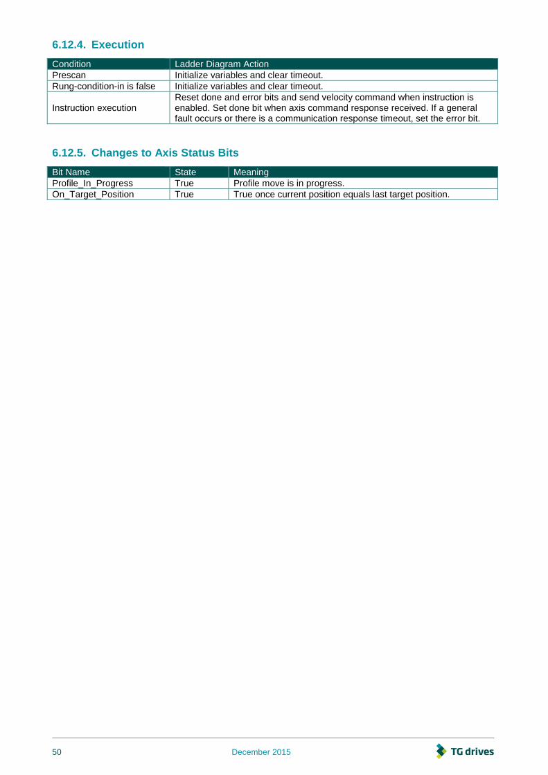
6.12.4. Execution
Condition Ladder Diagram Action
Prescan Initialize variables and clear timeout.
Rung-condition-in is false Initialize variables and clear timeout.
Instruction execution Reset done and error bits and send velocity command when instruction is enabled. Set done bit when axis command response received. If a general fault occurs or there is a communication response timeout, set the error bit.
6.12.5. Changes to Axis Status Bits
Bit Name State Meaning
Profile_In_Progress True Profile move is in progress.
On_Target_Position True True once current position equals last target position.

December 2015 51
6.13. Motion Axis Shutdown (AKD_Shutdown)
Description
The motion axis shutdown (AKD_Shutdown) instruction executes a controlled stop, then disables the servo
loop, disables drive output, and places the axis into the Shutdown state. This instruction is also referred to as
a hard stop. The shutdown state disables the drive output and deactivates the servo loop.
Another action initiated by the AKD_Shutdown instruction is the clearing of all motion processes in progress
and the clearing of all the motion status bits. Associated with this action, the command also clears all motion
instruction IP bits that are currently set for the targeted axis.
Another characteristic of the Shutdown state is that any instruction that initiates axis motion is blocked from
execution. Attempts to do so result in an execution error. By executing the Shutdown Reset instruction or
disabling and re-enabling the drive motion can be successfully initiated again.
The axis will remain in the shutdown state until a Motion Axis Shutdown Reset (AKD_Shutdown_Reset)
instruction executes or the drive is disabled and re-enabled. Corresponds to the MASD instruction in
Rockwell drives.
1. The AKD_Shutdown instruction execution may take multiple scans to execute because it
requires transmission of a message to the motion module. The Done (.DN) bit is not set
immediately, but only after the shutdown is set.
This is a transitional instruction:
In ladder diagram, toggle the rung-condition-in from cleared to set each time the
instruction should execute.
6.13.1. Operands
Operand Type Format Description
AKD_Shutdown AKD_SHUTDOWN Tag Control tag for this instruction.
Axis AKD_AXIS Tag The name of the axis to shut down.
6.13.2. AKD_SHUTDOWN Structure
Mnemonic Data Type Description
.EnableIn BOOL The enable input bit indicates that the instruction is enabled. It remains set until the instruction completes and the rung-condition-in goes false.
.EnableOut BOOL The enable output bit is the output of the enable input bit.
.DN (Done) BOOL The done bit indicates when the axis is successfully shutdown.
.ER (Error) BOOL The error bit indicates if the instruction detects an error.

52 December 2015
6.13.3. Execution
Condition Ladder Diagram Action
rung-condition-in is false Clears hard stop command.
instruction execution Send hard stop command when instruction is enabled. Set done bit when profile in progress is cleared. If a general fault occurs set the error bit.
6.13.4. Changes to Axis Status Bits
Bit Name State Meaning
Profile_In_Progress True No move is in progress
Enable True Axis is in Disabled state with the servo loop inactive.

December 2015 53
6.14. Motion Axis Shutdown Reset (AKD_Shutdown_Reset)
6.14.1. Description
Use the motion axis shutdown reset (AKD_Shutdown_Reset) instruction to transition an axis from the
Shutdown state to the Disabled ready state. All faults associated with the specified axis are automatically
cleared. Corresponds to the MASR instruction in Rockwell drives.
1. The AKD_Shutdown_Reset instruction execution may take multiple scans to execute because it
requires transmission of a message to the motion module and time for the drive to execute the
command. The Done (.DN) bit is not set immediately, but only after the drive is reset.
This is a transitional instruction:
In ladder diagram, toggle the rung-condition-in from cleared to set each time the
instruction should execute.
6.14.2. Operands
Operand Type Format Description
AKD_Shutdown_Reset AKD_SHUTDOWN_RESET Tag Control tag for this instruction.
Axis AKD_AXIS Tag The name of the axis to reset.
6.14.3. AKD_SHUTDOWN_RESET Structure
Mnemonic Data Type Description
.EnableIn BOOL The enable input bit indicates that the instruction is enabled. It remains set until the instruction completes and the rung-condition-in goes false.
.EnableOut BOOL The enable output bit is the output of the enable input bit.
.DN (Done) BOOL The done bit indicates when the axis is successfully reset.
.ER (Error) BOOL The error bit indicates if the instruction detects an error.
6.14.4. Execution
Condition Ladder Diagram Action
Prescan Initialize variables and clear timeout.
Rung-condition-in is false Initialize variables and clear timeout.
Instruction execution Reset done and error bits, disable axis, and reset faults. Set done bit when all axis command responses received. If a general fault occurs or there is a communication response timeout, set the error bit.
6.14.5. Changes to Axis Status Bits
Bit Name State Meaning
General_Fault False No general fault is present.
Enable False Axis is disabled.
FE_Fault False No following error fault is present.
Block_Fault False No block execution fault is present.

54 December 2015
6.15. Motion Axis Smooth Stop (AKD_Stop_Smooth)
6.15.1. Description
Use the motion axis smooth stop (AKD_Stop_Smooth) instruction to end any controlled motion in process for
the axis with a decelerated stop. The instruction stops the motion without disabling the servo loop. This
command defaults to stop at the deceleration rate set for the current motion. Corresponds to the MAS
instruction in Rockwell drives.
Use the instruction to:
Stop a specific motion process such as jogging or moving
Stop the axis completely
1. The AKD_Stop_Smooth instruction execution may take multiple scans to execute because it
requires transmission of a message to the motion module and time for the drive to execute the
command. The Done (.DN) bit is set once the motion stops.
6.15.2. Operands
Operand Type Format Description
AKD_Stop_Smooth AKD_STOP_SMOOTH Tag Control tag for this instruction.
Axis AKD_AXIS Tag The name of the axis to stop.
6.15.3. AKD_STOP_SMOOTH Structure
Mnemonic Data Type Description
.EnableIn BOOL The enable input bit indicates that the instruction is enabled. It remains set until the instruction completes and the rung-condition-in goes false.
.EnableOut BOOL The enable output bit is the output of the enable input bit.
.DN (Done) BOOL The done bit indicates when the stop command has completed and the motion has stopped.
.ER (Error) BOOL The error bit indicates if the instruction detects an error.
.IP (In Process) BOOL The in process bit is set when the command is enabled and remains true until the stop is complete.
6.15.4. Execution
Condition Ladder Diagram Action
Rung-condition-in is false Initialize variables.
Instruction execution Send smooth stop to axis. Set done bit when axis command is sent. If a general fault occurs, set the error bit.
6.15.5. Changes to Axis Status Bits
Bit Name State Meaning
Profile_In_Progress False No profile move executing.

December 2015 55
6.16. Motion Axis Get Position Controller Attribute
(AKD_Get_Attribute)
6.16.1. Description
Use the motion axis get attribute (AKD_Get_Attribute) instruction to query a Position Controller attribute from
an axis. This instruction provides quick access to a special set of drive parameters which can always be
accessed in one communication cycle. The output value will be updated with live values each cycle as long
as this instruction is enabled.
1. This instruction must not be enabled at the same time as the AKD_Get_Parameter instruction.
See Appendix A: Position Controller Object Attributes for a list of available attributes and numbering.
6.16.2. Operands
Operand Type Format Description
AKD_Get_Attribute AKD_GET_ATTRIBUTE Tag Control tag for this instruction.
Axis AKD_AXIS Tag The name of the axis to query.
Attribute_Number INT Immediate (See Appendix A: Position Controller Object Attributes)
Attribute_Value DINT Tag Output tag to which the value of the attribute is passed.
6.16.3. AKD_GET_ATTRIBUTE Structure
Mnemonic Data Type Description
.EnableIn BOOL The enable input bit indicates that the instruction is enabled. It remains set until the instruction completes and the rung-condition-in goes false.
.EnableOut BOOL The enable output bit is the output of the enable input bit.
.DN (Done) BOOL The done bit indicates when the get attribute command has been completed.
.ER (Error) BOOL The error bit indicates if the instruction detects an error.
6.16.4. Execution
Condition Ladder Diagram Action
Pre-scan Initialize variables and clear timeout.
Rung-condition-in is false Initialize variables and clear timeout.
Instruction execution Send command to axis to request value. Set done bit and copy response to attribute value output when axis response is received. If a general fault or timeout occurs, set the error bit.
6.16.5. Changes to Axis Status Bits
Bit Name State Meaning
(none)

56 December 2015
6.17. Motion Axis Get Parameter (AKD_Get_Parameter)
6.17.1. Description
Use the motion axis get parameter (AKD_Get_Parameter) instruction to query a drive parameter from an
axis. The length of time to return the value is highly dependent on the particular parameter. The value will be
latched when the instruction is done. Clear and re-enable the instruction to get an updated value.
6.17.2. Operands
Operand Type Format Description
AKD_Get_Parameter AKD_GET_PARAMETER Tag Control tag for this instruction.
Axis AKD_AXIS Tag The name of the axis to query.
Parameter_Number INT Immediate (See Appendix B: AKD Parameters)
Parameter_Value DINT Immediate Output tag to which the value of the parameter is passed.
6.17.3. AKD_GET_PARAMETER Structure
Mnemonic Data Type Description
.EnableIn BOOL The enable input bit indicates that the instruction is enabled. It remains set until the instruction completes and the rung-condition-in goes false.
.EnableOut BOOL The enable output bit is the output of the enable input bit.
.DN (Done) BOOL The done bit indicates when the get parameter command has been completed.
.ER (Error) BOOL The error bit indicates if the instruction detects an error.
6.17.4. Execution
Condition Ladder Diagram Action
Pre-scan Initialize variables and clear timeout.
Rung-condition-in is false Initialize variables and clear timeout.
Instruction execution Send command to axis to request value. Set done bit and copy response to parameter value output when axis response is received. If a general fault or timeout occurs, set the error bit.
6.17.5. Changes to Axis Status Bits
Bit Name State Meaning
(none)

December 2015 57
6.18. Motion Axis Set Position Controller Attribute
(AKD_Set_Attribute)
6.18.1. Description
Use the motion axis set attribute (AKD_Set_Attribute) instruction to set a Position Controller attribute for an
axis. This instruction provides quick access to a special set of drive parameters which can always be set in
one communication cycle. See Appendix A: Position Controller Object Attributes for a list of available
attributes and numbering.
6.18.2. Operands
Operand Type Format Description
AKD_Set_Attribute AKD_SET_ATTRIBUTE Tag Control tag for this instruction.
Axis AKD_AXIS Tag The name of the axis to modify.
Attribute_Number INT Immediate (See Appendix A: Position Controller Object Attributes)
Attribute_Value DINT Immediate Value to which the specified attribute will be set.
6.18.3. AKD_SET_ATTRIBUTE Structure
Mnemonic Data Type Description
.EnableIn BOOL The enable input bit indicates that the instruction is enabled. It remains set until the instruction completes and the rung-condition-in goes false.
.EnableOut BOOL The enable output bit is the output of the enable input bit.
.DN (Done) BOOL The done bit indicates when the set attribute command has been completed.
.ER (Error) BOOL The error bit indicates if the instruction detects an error.
6.18.4. Execution
Condition Ladder Diagram Action
Pre-scan Initialize variables and clear timeout.
Rung-condition-in is false Initialize variables and clear timeout.
Instruction execution Send command to axis to set value. Set done bit when axis response is received. If a general fault or timeout occurs, set the error bit.
6.18.5. Changes to Axis Status Bits
Bit Name State Meaning
(none)

58 December 2015
6.19. Motion Axis Set Parameter (AKD_Set_Parameter)
6.19.1. Description
Use the motion axis set parameter (AKD_Set_Parameter) instruction to modify a drive parameter or execute
a drive command on an axis. The time required to execute the command is highly dependent on the
particular parameter. See Appendix B: AKD Parameters for a list of available parameters and numbering.
6.19.2. Operands
Operand Type Format Description
AKD_Set_Parameter AKD_SET_PARAMETER Tag Control tag for this instruction.
Axis AKD_AXIS Tag The name of the axis to modify.
Parameter_Number INT Immediate (See Appendix B: AKD Parameters)
Parameter_Value DINT Immediate Value to which the specified parameter will be set.
6.19.3. AKD_SET_PARAMETER Structure
Mnemonic Data Type Description
.EnableIn BOOL The enable input bit indicates that the instruction is enabled. It remains set until the instruction completes and the rung-condition-in goes false.
.EnableOut BOOL The enable output bit is the output of the enable input bit.
.DN (Done) BOOL The done bit indicates when the set parameter command has been completed.
.ER (Error) BOOL The error bit indicates if the instruction detects an error.
6.19.4. Execution
Condition Ladder Diagram Action
Pre-scan Initialize variables and clear timeout.
Rung-condition-in is false Initialize variables and clear timeout.
Instruction execution Send command to axis to set value. Set done bit when axis response is received. If a general fault or timeout occurs, set the error bit.
6.19.5. Changes to Axis Status Bits
Bit Name State Meaning
(none)

December 2015 59
6.20. Motion Axis Set Units (AKD_Set_Units)
6.20.1. Description
Use the motion axis set units (AKD_Set_Units) instruction to set the current unit system used on an axis.
At the moment, only mode 0 (EIP.POSUNIT=65536 and EIP.PROFUNIT=65536) is available. These scaling
values can also be modified directly through EtherNet/IP or Workbench. See the AKD EtherNet/IP User
Manual for more information about unit scaling.
6.20.2. Operands
Operand Type Format Description
AKD_Set_Units AKD_SET_UNITS Tag Control tag for this instruction.
Axis AKD_AXIS Tag The name of the axis to modify.
Units SINT Immediate For units Enter:
Counts 0
6.20.3. AKD_SET_UNITS Structure
Mnemonic Data Type Description
.EnableIn BOOL The enable input bit indicates that the instruction is enabled. It remains set until the instruction completes and the rung-condition-in goes false.
.EnableOut BOOL The enable output bit is the output of the enable input bit.
.DN (Done) BOOL The done bit indicates when the set units command has been completed.
.ER (Error) BOOL The error bit indicates if the instruction detects an error.
6.20.4. Execution
Condition Ladder Diagram Action
Pre-scan Initialize variables and clear timeout.
Rung-condition-in is false Initialize variables and clear timeout.
Instruction execution Send command to axis to set units and if necessary update settings. Set done bit when axis response is received. If a general fault or timeout occurs, set the error bit.
6.20.5. Changes to Axis Status Bits
Bit Name State Meaning
(none)

60 December 2015
6.21. Motion Axis Torque (AKD_Torque_Move)
6.21.1. Description
Use the AKD_Torque_Move instruction to move an axis at a constant torque without regard to position.
Drive must be enabled and in torque mode in order to execute this instruction.
1. The AKD_Shutdown_Reset instruction execution may take multiple scans to execute because it
requires transmission of a message to the motion module and time for the drive to execute the
command. The Done (.DN) bit is not set immediately, but only after the faults have been cleared.
6.21.2. Operands
Operand Type Format Description
AKD_Torque_Move AKD_TORQUE_MOVE Tag Control tag for this instruction.
Axis AKD_AXIS Tag The name of the axis to enable.
Torque DINT Immediate Desired torque in milliarms.
6.21.3. AKD_TORQUE_MOVE Structure
Mnemonic Data Type Description
.EnableIn BOOL The enable input bit indicates that the instruction is enabled. It remains set until the instruction completes and the rung-condition-in goes false.
.EnableOut BOOL The enable output bit is the output of the enable input bit.
.DN (Done) BOOL The done bit indicates when the torque instruction is successful.
.ER (Error) BOOL The error bit indicates if the instruction detects an error.
6.21.4. Programming Guidelines
Guideline Details
In ladder diagram, toggle the rung condition each time you want to execute the instruction.
This is a transitional instruction. In ladder diagram, toggle the rung-condition-in from cleared to set each time you want to execute the instruction.
Use an AKD_Stop_Smooth instruction, or command a zero torque, to stop the move.
See Motion Axis Smooth Stop (AKD_Stop_Smooth) (➜ p. )
for more details.
6.21.5. Execution
Condition Ladder Diagram Action
Pre-scan Initialize variables and clear timeout.
Rung-condition-in is false Reset in progress bit when axis profile is no longer in progress.
Instruction execution Reset done and error bits, then set torque. Start move and set the done bit to indicate command has been loaded to the drive. If a general fault occurs or there is a communication response timeout, set the error bit.
6.21.6. Changes to Axis Status Bits
Bit Name State Meaning
Profile_In_Progress True Profile move is in progress.

December 2015 61
6.22. Fault Reset (AKD_Fault_Reset)
6.22.1. Description
This instruction will attempt to clear faults. The drive must be disabled before executing this instruction.
1. In most cases, AKD_Shutdown_Reset should be used instead, as it disables the drive and
checks that faults have been cleared successfully.
2. The AKD_Fault_Reset instruction execution may take multiple scans to execute because it
requires transmission of a message to the motion module and time for the drive to execute the
command. The Done (.DN) bit is not set immediately, but only after the faults have been cleared.
6.22.2. Operands
Operand Type Format Description
AKD_Fault_Reset AKD_FAULT_RESET Tag Control tag for this instruction.
Axis AKD_AXIS Tag The name of the axis to reset.
6.22.3. AKD_FAULT_RESET Structure
Mnemonic Data Type Description
.EnableIn BOOL The enable input bit indicates that the instruction is enabled. It remains set until the instruction completes and the rung-condition-in goes false.
.EnableOut BOOL The enable output bit is the output of the enable input bit.
.DN (Done) BOOL The done bit indicates when the FaultReset instruction has completed. Check the General_Fault bit to see if faults were all successfully cleared.
.ER (Error) BOOL The error bit indicates if the instruction detects an error.
6.22.4. Programming Guidelines
Guideline Details
In ladder diagram, toggle the rung condition each time you want to execute the instruction.
This is a transitional instruction. In ladder diagram, toggle the rung-condition-in from cleared to set each time you want to execute the instruction.
6.22.5. Execution
Condition Ladder Diagram Action
Pre-scan Initialize variables and clear timeout.
Rung-condition-in is false Reset in progress bit when axis profile is no longer in progress.
Instruction execution Enable the instruction to initiate the clearing of faults. If a fault condition remains, or the drive is enabled, faults will still be reported when the instruction completes.
6.22.6. Changes to Axis Status Bits
Bit Name State Meaning
General_Fault False No general fault is present (if successful)
FE_Fault False No following error fault is present
Block_Fault False No block execution fault is present

62 December 2015
7. Troubleshooting
7.1. Introduction
Problems occur for a variety of reasons, depending on the conditions in your program. The causes of errors
in multi-axis systems can be especially complex. If you cannot resolve a fault or other issue using the
troubleshooting guidance presented below, customer support can give you further assistance.
7.2. .ER (Error) bit
.ER (Error) Bit is set on an AKD add-on instruction if the instruction detects an error. Potential sources of
error are:
Unconfigured axis was specified
Communication timeout
Operand value out of range
7.2.1. Unconfigured Axis was Specified
Verify the Axis tag matches the name of the axis you are trying to modify.
7.2.2. Communication Timeout
The instructions share a common “timeout” value in the controller tag Axis_Internal.CommandTimeout. This
value is used to count down when a command is sent, to ensure a response is received as expected. In
some project configurations, this timeout may need to be increased, such as if the rung for an Add-On
instruction is only scanned once per second. In this case, increase the value of CommandTimeout [ms]. Note
that with the default value of 0, the CommandTimeout is ignored by all instructions and will never timeout.

December 2015 63
7.2.3. Operand value out of range
Refer to Chapter 5 for valid operand values. For specific AKD pararmeters, data size and data type are
shown in Appendix B. Further information on and descriptions of AKD parameters can be found in
Workbench Help section.
7.3. AKD Fault
For most AKD Faults, refer to the Fault and Warning Messages table in the AKD Installation Manual for
further explanation and possible remedies.
7.3.1. Fieldbus Fault – F702
AKD F702 Fault is set if communication between the drive and controller is lost. The primary cause of this
fault is a communication timeout between the drive and controller. The controller is responsible for setting
the Requested Packet Interval rate at which cyclic messages are exchanged between the drive and control.
If the rate is set too short, communication may timeout. 10ms is the fastest support rate for EtherNet/IP on
AKD. For simultaneous operation of Workbench and EtherNet/IP communications, the rate should be
reduced to 20ms.

64 December 2015
8. Appendix A: Supported EtherNet/IP Objects and Attributes
8.1. Position Controller Object 0x25
Attribute ID (Decimal Value)
Name Access Rule Type Description
1 Number of Attributes
Get USINT Returns the total number of attributes supported by this object in this device.
2 Attribute List Get Array of USINT
Returns an array with a list of the attributes supported by this object in this device.
3 Mode Get/Set USINT Operating mode. 0 = Position mode(default), 1 = Velocity mode, 2 = Torque mode.
4 Position Units
Get/Set DINT Position Units ratio value is the number of actual position feedback counts equal to one position unit (default 1).
5 Profile Units Get/Set DINT
Profile Units ratio value is the number of actual position feedback counts per second or second2 equal to one velocity, acceleration or deceleration unit (default 1).
6 Target Position
Get/Set DINT Specifies the target position in counts.
7 Target Velocity
Get/Set DINT Specifies the Target Velocity in counts per second.
8 Acceleration Get/Set DINT Not used yet.
9 Deceleration Get/Set DINT Not used yet.
10 Incremental Position Flag
Get/Set BOOL Incremental Position Flag 0 := absolute, 1:= incremental.
11 Load Data/Profile Handshake
Get/Set BOOL Used to Load Command Data, Start a Profile Move, and indicate that a Profile Move is in progress.
17 Enable Get/Set BOOL Enable Output (same as DRV.EN).
25 Torque Get/Set DINT Output torque.
58 Load Data Complete
Get/Set BOOL Indicates that valid data for a valid I/O command message type has been loaded into the position controller device.
100 Home Mode Get/Set INT See home mode section of the AKD User Manual
101 Home Move Set BOOL Initiate a home move.

December 2015 65
9. Appendix B: Parameter Listing
The parameters in this list correspond to drive parameters available in Workbench and are described in the
Workbench help documentation and the AKD User's Guide.
Position values are scaled according to EIP.PROSUNIT.
Velocity and Acceleration values are scaled according to EIP.PROFUNIT.
Other floating point values are multiplied by 1000, such that a value displayed in Workbench as 1.001 will be
transmitted through EtherNet/IP as 1001.
The lower 32-bits of parameters with the data size 8 can be read by accessing the instance number for the 8
byte parameter incremented by 1.
Instance Parameter Data Size Data Type
1 AIN.CUTOFF 4 Byte Float
2 AIN.DEADBAND 4 Byte Float
3 AIN.ISCALE 4 Byte Float
4 AIN.OFFSET 2 Byte Signed Float
5 AIN.PSCALE 8 Byte (truncated to 4 Byte) Position
7 AIN.VALUE 4 Byte Float
8 AIN.VSCALE 4 Byte Velocity
9 AIN.ZERO Command None
10 AOUT.ISCALE 4 Byte Float
11 AOUT.MODE 2 Byte Integer
12 AOUT.OFFSET 4 Byte Signed Float
13 AOUT.PSCALE 8 Byte (truncated to 4 Byte) Position
15 AOUT.VALUE 4 Byte Signed Float
17 AOUT.VALUEU 4 Byte Signed Float
19 AOUT.VSCALE 4 Byte Velocity
20 BODE.EXCITEGAP 1 Byte Integer
21 BODE.FREQ 4 Byte Float
22 BODE.IAMP 4 Byte Signed Float
23 BODE.INJECTPOINT 1 Byte Integer
24 BODE.MODE 1 Byte Integer
25 BODE.MODETIMER 4 Byte Integer
26 BODE.PRBDEPTH 1 Byte Integer
27 BODE.VAMP 8 Byte Signed (truncated to 4 Byte Signed) Velocity
28 CAP0.EDGE 1 Byte Integer
29 CAP0.EN 1 Byte Integer
30 CAP0.EVENT 1 Byte Integer
31 CAP0.FILTER 1 Byte Integer
32 CAP0.MODE 1 Byte Integer
33 CAP0.PLFB 8 Byte Signed (truncated to 4 Byte Signed) Position
35 CAP0.PREEDGE 1 Byte Integer
36 CAP0.PREFILTER 1 Byte Integer
37 CAP0.PRESLECT 1 Byte Integer
38 CAP0.STATE 1 Byte Integer
39 CAP0.T 4 Byte Integer
40 CAP0.TRIGGER 1 Byte Integer
41 CAP1.EDGE 1 Byte Integer
42 CAP1.EN 1 Byte Integer
43 CAP1.EVENT 1 Byte Integer
44 CAP1.FILTER 1 Byte Integer
45 CAP1.MODE 1 Byte Integer
46 CAP1.PLFB 8 Byte Signed (truncated to 4 Byte Signed) Position
48 CAP1.PREEDGE 1 Byte Integer
49 CAP1.PREFILTER 1 Byte Integer
50 CAP1.PRESELECT 1 Byte Integer
51 CAP1.STATE 1 Byte Integer
52 CAP1.T 4 Byte Integer
53 CAP1.TRIGGER 1 Byte Integer

66 December 2015
Instance Parameter Data Size Data Type
54 CS.DEC 8 byte (truncated to 4 Byte) Acceleration
56 CS.STATE 1 Byte Integer
57 CS.TO 4 Byte Integer
58 CS.VTHRESH 8 Byte (truncated to 4 Byte) Velocity
59 DIN.ROTARY 1 Byte Integer
60 DIN.STATES 1 Byte Array
61 DIN1.INV 1 Byte Integer
62 DIN1.MODE 2 Byte Integer
63 DIN1.PARAM 8 Byte Signed (truncated to 4 Byte Signed) Varies
65 DIN1.STATE 1 Byte Integer
66 DIN2.INV 1 Byte Integer
67 DIN2.MODE 2 Byte Integer
68 DIN2.PARAM 8 Byte Signed (truncated to 4 Byte Signed) Varies
70 DIN2.STATE 1 Byte Integer
71 DIN3.INV 1 Byte Integer
72 DIN3.MODE 2 Byte Integer
73 DIN3.PARAM 8 Byte Signed (truncated to 4 Byte Signed) Varies
75 DIN3.STATE 1 Byte Integer
76 DIN4.INV 1 Byte Integer
77 DIN4.MODE 2 Byte Integer
78 DIN4.PARAM 8 Byte Signed (truncated to 4 Byte Signed) Varies
80 DIN4.STATE 1 Byte Integer
81 DIN5.INV 1 Byte Integer
82 DIN5.MODE 2 Byte Integer
83 DIN5.PARAM 8 Byte Signed (truncated to 4 Byte Signed) Varies
85 DIN5.STATE 1 Byte Integer
86 DIN6.INV 1 Byte Integer
87 DIN6.MODE 2 Byte Integer
88 DIN6.PARAM 8 Byte Signed (truncated to 4 Byte Signed) Varies
90 DIN6.STATE 1 Byte Integer
91 DIN7.INV 1 Byte Integer
92 DIN7.MODE 2 Byte Integer
93 DIN7.PARAM 8 Byte Signed (truncated to 4 Byte Signed) Varies
95 DIN7.STATE 1 Byte Integer
96 DOUT.CTRL 1 Byte Integer
97 DOUT.RELAYMODE 1 Byte Integer
98 DOUT.STATES 1 Byte Array
99 DOUT1.MODE 1 Byte Integer
100 DOUT1.PARAM 4 Byte Signed Float
102 DOUT1.STATE 1 Byte Integer
103 DOUT1.STATEU 1 Byte Integer
104 DOUT2.MODE 1 Byte Integer
105 DOUT2.PARAM 4 Byte Signed Float
107 DOUT2.STATE 1 Byte Integer
108 DOUT2.STATEU 1 Byte Integer
109 DRV.ACC 8 Byte (truncated to 4 Byte) Acceleration
111 DRV.ACTIVE 1 Byte Integer
112 DRV.CLRFAULTHIST Command None
113 DRV.CLRFAULTS Command None
114 DRV.CMDSOURCE 1 Byte Integer
115 DRV.DBILIMIT 4 Byte Float
116 DRV.DEC 8 Byte (truncated to 4 Byte) Acceleration
118 DRV.DIR 1 Byte Integer
119 DRV.DI Command None
120 DRV.DISMODE 1 Byte Integer
121 DRV.DISSOURCES 2 Byte Integer
122 DRV.DISTO 4 Byte Integer
123 DRV.EMUEDIR 1 Byte Integer
124 DRV.EMUEMODE 2 Byte Integer
125 DRV.EMUEMTURN 4 Byte Integer

December 2015 67
Instance Parameter Data Size Data Type
126 DRV.EMUERES 4 Byte Integer
127 DRV.EMUEZOFFSET 2 Byte Integer
128 DRV.EN Command None
129 DRV.ENDEFAULT 1 Byte Integer
130 DRV.HANDWHEEL 4 Byte Integer
131 DRV.HWENMODE 1 Byte Integer
132 DRV.ICONT 4 Byte Signed Float
133 DRV.IPEAK 4 Byte Signed Float
134 DRV.IZERO 4 Byte Float
135 DRV.MOTIONSTAT 4 Byte Integer
136 DRV.OPMODE 1 Byte Integer
137 DRV.RSTVAR Command None
138 DRV.STOP Command None
139 DRV.TYPE 1 Byte Integer
140 DRV.ZERO 1 Byte Integer
141 FB1.BISSBITS 1 Byte Integer
142 FB1.ENCRES 4 Byte Integer
143 FB1.IDENTIFIED 1 Byte Integer
144 FB1.INITSIGNED 1 Byte Signed Integer
145 FB1.MECHPOS 4 Byte Integer
146 FB1.OFFSET 8 Byte Signed (truncated to 4 Byte Signed) Position
148 FB1.ORIGIN 8 Byte (truncated to 4 Byte) Position
150 FB1.PFIND 1 Byte Integer
151 FB1.PFINDCMDU 4 Byte Float
152 FB1.POLES 2 Byte Integer
153 FB1.PSCALE 1 Byte Integer
154 FB1.RESKTR 4 Byte Float
155 FB1.RESREFPHASE 4 Byte Signed Float
156 FB1.SELECT 1 Byte Signed Integer
157 FB1.TRACKINGCAL 1 Byte Integer
158 FBUS.PARAM01 4 Byte Integer
159 FBUS.PARAM02 4 Byte Integer
160 FBUS.PARAM03 4 Byte Integer
161 FBUS.PARAM04 4 Byte Integer
162 FBUS.PARAM05 4 Byte Integer
163 FBUS.PARAM06 4 Byte Integer
164 FBUS.PARAM07 4 Byte Integer
178 FBUS.PLLTHRESH 2 Byte Integer
179 FBUS.SAMPLEPERIOD 1 Byte Integer
180 FBUS.SYNCACT 4 Byte Integer
181 FBUS.SYNCDIST 4 Byte Integer
182 FBUS.SYNCWND 4 Byte Integer
183 FBUS.TYPE 1 Byte Integer
184 GEAR.ACCMAX 8 Byte (truncated to 4 Byte) Acceleration
186 GEAR.DECMAX 8 Byte (truncated to 4 Byte) Acceleration
188 GEAR.IN 2 Byte Integer
189 GEAR.MODE 2 Byte Integer
190 GEAR.MOVE Command None
191 GEAR.OUT 2 Byte signed Integer
192 GEAR.VMAX 8 Byte (truncated to 4 Byte) Velocity
193 HOME.ACC 8 Byte (truncated to 4 Byte) Acceleration
195 HOME.AUTOMOVE 1 Byte Integer
196 HOME.DEC 8 Byte (truncated to 4 Byte) Acceleration
198 HOME.DIR 2 Byte Integer
199 HOME.DIST 8 Byte Signed (truncated to 4 Byte Signed) Position
201 HOME.FEEDRATE 2 Byte Integer
202 HOME.IPEAK 4 Byte Signed Float
204 HOME.MODE 2 Byte Integer
205 HOME.MOVE Command None
206 HOME.P 8 Byte Signed (truncated to 4 Byte Signed) Position

68 December 2015
Instance Parameter Data Size Data Type
208 HOME.PERRTHRESH 8 Byte Signed (truncated to 4 Byte Signed) Position
210 HOME.SET Command None
211 HOME.V 8 Byte (truncated to 4 Byte) Velocity
212 HWLS.NEGSTATE 1 Byte Integer
213 HWLS.POSSTATE 1 Byte Integer
214 IL.BUSFF 4 Byte Signed Float
215 IL.CMD 4 Byte Signed Float
217 IL.FB 4 Byte Signed Float
218 IL.FF 4 Byte Float
219 IL.FOLDFTHRESH 4 Byte Float
220 IL.FOLDFTHRESHU 4 Byte Signed Float
221 IL.FOLDWTHRESH 4 Byte Signed Float
222 IL.FRICTION 4 Byte Float
223 IL.IFOLDS 4 Byte Float
224 IL.IUFB 4 Byte Signed Float
225 IL.IVFB 4 Byte Signed Float
226 IL.KACCFF 4 Byte Signed Float
227 IL.KBUSFF 4 Byte Float
228 IL.KP 4 Byte Float
229 IL.KPDRATIO 4 Byte Float
230 IL.KVFF 4 Byte Signed Float
231 IL.LIMITN 4 Byte Signed Float
232 IL.LIMITP 4 Byte Signed Float
233 IL.MFOLDD 4 Byte Float
234 IL.MFOLDR 4 Byte Float
235 IL.MFOLDT 4 Byte Float
236 IL.MIFOLD 4 Byte Float
237 IL.OFFSET 4 Byte Signed Float
238 IL.VCMD 2 Byte Signed Integer
239 IL.VUFB 2 Byte Signed Integer
240 IL.VVFB 2 Byte Signed Integer
241 MOTOR.AUTOSET 1 Byte Integer
242 MOTOR.BRAKE 1 Byte Integer
243 MOTOR.BRAKERLS 1 Byte Integer
244 MOTOR.CTF0 4 Byte Float
245 MOTOR.ICONT 4 Byte Float
246 MOTOR.IDDATAVALID 1 Byte Integer
247 MOTOR.INTERTIA 4 Byte Float
248 MOTOR.IPEAK 4 Byte Float
249 MOTOR.KT 4 Byte Float
250 MOTOR.LQLL 4 Byte Float
251 MOTOR.PHASE 2 Byte Integer
252 MOTOR.PITCH 4 Byte Float
253 MOTOR.POLES 2 Byte Integer
254 MOTOR.R 4 Byte Float
255 MOTOR.RTYPE 1 Byte Integer
256 MOTOR.TBRAKEAPP 2 Byte Integer
257 MOTOR.TBRAKERLS 2 Byte Integer
258 MOTOR.TEMP 4 Byte Integer
259 MOTOR.TEMPFAULT 4 Byte Integer
260 MOTOR.TEMPWARN 4 Byte Integer
261 MOTOR.TYPE 1 Byte Integer
262 MOTOR.VMAX 2 Byte Integer
263 MOTOR.VOLTMAX 2 Byte Integer
264 MT,ACC 8 Byte (truncated to 4 Byte) Acceleration
266 MT.CLEAR 2 Byte Signed Integer
267 MT.CNTL 4 Byte Integer
268 MT.CONTINUE Command None
269 MT.DEC 8 Byte (truncated to 4 Byte) Acceleration
271 MT.EMERGMT 2 Byte Signed Integer

December 2015 69
Instance Parameter Data Size Data Type
272 MT.LOAD Command None
273 MT.MOVE 2 Byte Command None
274 MT.MTNEXT 1 Byte Integer
275 MT.NUM 1 Byte Integer
276 MT.P 8 Byte Signed (truncated to 4 Byte Signed) Position
278 MT.SET 1 Byte Command None
279 MT.TNEXT 2 Byte Integer
280 MT.TNUM 1 Byte Integer
281 MT.TPOSWND 8 Byte Signed (truncated to 4 Byte Signed) Position
283 MT.TVELWND 8 Byte (truncated to 4 Byte) Velocity
284 MT.V 8 Byte (truncated to 4 Byte) Velocity
285 MT.VCMD 8 Byte Signed (truncated to 4 Byte Signed) Velocity
286 PL.CMD 8 Byte (truncated to 4 Byte) Position
288 PL.ERR 8 Byte (truncated to 4 Byte) Position
290 PL.ERRMODE 1 Byte Integer
291 PL.ERRFTHRESH 8 Byte (truncated to 4 Byte) Position
293 PL.ERRWTHRESH 8 Byte (truncated to 4 Byte) Position
295 PL.FB 8 Byte Signed (truncated to 4 Byte Signed) Position
297 PL.FBSOURCE 1 Byte Integer
298 PL.INTINMAX 8 Byte (truncated to 4 Byte) Position
300 PL.INTOUTMAX 8 Byte (truncated to 4 Byte) Position
302 PL.KI 4 Byte Float
303 PL.KP 4 Byte Float
304 PL.MODP1 8 Byte Signed (truncated to 4 Byte Signed) Position
306 PL.MODP2 8 Byte Signed (truncated to 4 Byte Signed) Position
308 PL.MODPDIR 1 Byte Integer
309 PL.MODPEN 1 Byte Integer
310 PLS.EN 2 Byte Integer
311 PLS.MODE 2 Byte Integer
312 PLS.P1 8 Byte Signed (truncated to 4 Byte Signed) Position
314 PLS.P2 8 Byte Signed (truncated to 4 Byte Signed) Position
316 PLS.P3 8 Byte Signed (truncated to 4 Byte Signed) Position
318 PLS.P4 8 Byte Signed (truncated to 4 Byte Signed) Position
320 PLS.P5 8 Byte Signed (truncated to 4 Byte Signed) Position
322 PLS.P6 8 Byte Signed (truncated to 4 Byte Signed) Position
324 PLS.P7 8 Byte Signed (truncated to 4 Byte Signed) Position
326 PLS.P8 8 Byte Signed (truncated to 4 Byte Signed) Position
328 PLS.RESET 2 Byte Integer
329 PLS.STATE 2 Byte Integer
330 PLS.T1 2 Byte Integer
331 PLS.T2 2 Byte Integer
332 PLS.T3 2 Byte Integer
333 PLS.T4 2 Byte Integer
334 PLS.T5 2 Byte Integer
335 PLS.T6 2 Byte Integer
336 PLS.T7 2 Byte Integer
337 PLS.T8 2 Byte Integer
338 PLS.UNITS 1 Byte Integer
339 PLS.WIDTH1 8 Byte Signed (truncated to 4 Byte Signed) Position
341 PLS.WIDTH2 8 Byte Signed (truncated to 4 Byte Signed) Position
343 PLS.WIDTH3 8 Byte Signed (truncated to 4 Byte Signed) Position
345 PLS.WIDTH4 8 Byte Signed (truncated to 4 Byte Signed) Position
347 PLS.WIDTH5 8 Byte Signed (truncated to 4 Byte Signed) Position
349 PLS.WIDTH6 8 Byte Signed (truncated to 4 Byte Signed) Position
351 PLS.WIDTH7 8 Byte Signed (truncated to 4 Byte Signed) Position
353 PLS.WIDTH8 8 Byte Signed (truncated to 4 Byte Signed) Position
355 REC.ACTIVE 1 Byte Integer
356 REC.DONE 1 Byte Integer
357 REC.GAP 2 Byte Integer
358 REC.NUMPOINTS 2 Byte Integer

70 December 2015
Instance Parameter Data Size Data Type
359 REC.OFF Command None
360 REC.STOPTYPE 1 Byte Integer
361 REC.TRIG Command None
362 REC.TRIGPOS 1 Byte Integer
363 REC.TRIGPRMLIST - String
364 REC.TRIGSLOPE 1 Byte Integer
365 REC.TRIGTYPE 1 Byte Integer
366 REC.TRIGVAL 8 Byte Signed (truncated to 4 Byte Signed) Varies
368 REGEN.POWER 8 Byte (truncated to 4 Byte) Integer
370 REGEN.REXT 2 Byte Integer
371 REGEN.TEXT 4 Byte Float
372 REGEN.TYPE 1 Byte Signed Integer
373 REGEN.WATTEXT 2 Byte Integer
374 SM.I1 4 Byte Signed Float
375 SM.I2 4 Byte Signed Float
376 SM.MODE 2 Byte Integer
377 SM.MOVE Command None
378 SM.T1 2 Byte Integer
379 SM.T2 2 Byte Integer
380 SM.V1 8 Byte Signed (truncated to 4 Byte Signed) Velocity
381 SM.V2 8 Byte Signed (truncated to 4 Byte Signed) Velocity
382 STO.STATE 1 Byte Integer
383 SWLS.EN 2 Byte Integer
384 SWLS.LIMIT0 8 Byte Signed (truncated to 4 Byte Signed) Position
386 SWLS.LIMIT1 8 Byte Signed (truncated to 4 Byte Signed) Position
388 SWLS.STATE 2 Byte Integer
389 UNIT.ACCLINEAR 1 Byte Integer
390 UNIT.ACCROTARY 1 Byte Integer
391 UNIT.PIN 4 Byte Integer
392 UNIT.PLINEAR 1 Byte Integer
393 UNIT.POUT 4 Byte Integer
394 UNIT.PROTARY 1 Byte Integer
395 UNIT.VLINEAR 1 Byte Integer
396 UNIT.VROTARY 1 Byte Integer
397 VBUS.CALGAIN 4 Byte Float
398 VBUS.OVFTHRESH 2 Byte Integer
399 VBUS.OVWTHRESH 2 Byte Integer
400 VBUS.RMSLIMIT 1 Byte Integer
401 VBUS.UVFTHRESH 2 Byte Integer
402 VBUS.UVMODE 1 Byte Integer
403 VBUS.UVWTHRESH 2 Byte Integer
404 VBUS.VALUE 4 Byte Float
405 VL.ARPF1 4 Byte Float
406 VL.ARPF2 4 Byte Float
407 VL.ARPF3 4 Byte Float
408 VL.ARPF4 4 Byte Float
409 VL.ARPQ1 4 Byte Float
410 VL.ARPQ2 4 Byte Float
411 VL.ARPQ3 4 Byte Float
412 VL.ARPQ4 4 Byte Float
413 VL.ARTYPE1 1 Byte Integer
414 VL.ARTYPE2 1 Byte Integer
415 VL.ARTYPE3 1 Byte Integer
416 VL.ARTYPE4 1 Byte Integer
417 VL.ARZF1 4 Byte Float
418 VL.ARZF2 4 Byte Float
419 VL.ARZF3 4 Byte Float
420 VL.ARZF4 4 Byte Float
421 VL.ARZQ1 4 Byte Float
422 VL.ARZQ2 4 Byte Float

December 2015 71
Instance Parameter Data Size Data Type
423 VL.ARZQ3 4 Byte Float
424 VL.ARZQ4 4 Byte Float
425 VL.BUSFF 8 Byte Signed (truncated to 4 Byte Signed) Velocity
426 VL.CMD 8 Byte Signed (truncated to 4 Byte Signed) Velocity
427 VL.CMDU 8 Byte Signed (truncated to 4 Byte Signed) Velocity
428 VL.ERR 8 Byte Signed (truncated to 4 Byte Signed) Velocity
429 VL.FB 8 Byte Signed (truncated to 4 Byte Signed) Velocity
430 VL.FBFILTER 8 Byte Signed (truncated to 4 Byte Signed) Velocity
431 VL.FBSOURCE 1 Byte Integer
432 VL.FF 8 Byte Signed (truncated to 4 Byte Signed) Velocity
433 VL.GENMODE 2 Byte Velocity
434 VL.KBUSFF 4 Byte Float
435 VL.KI 4 Byte Float
436 VL.KO 4 Byte Float
437 VL.KP 4 Byte Float
438 VL.KVFF 4 Byte Float
439 VL.LIMITN 8 Byte Signed (truncated to 4 Byte Signed) Velocity
440 VL.LIMITP 8 Byte (truncated to 4 Byte) Velocity
441 VL.LMJR 4 Byte Float
442 VL.MODEL 8 Byte Signed (truncated to 4 Byte Signed) Velocity
443 VL.OBSBW 4 Byte Float
444 VL.OBSMODE 4 Byte Integer
445 VL.THRESH 8 Byte Signed (truncated to 4 Byte Signed) Velocity
446 WS.ARM Command None
447 WS.DISTMAX 8 Byte Signed (truncated to 4 Byte Signed) Position
449 WS.DISTMIN 8 Byte Signed (truncated to 4 Byte Signed) Position
451 WS.IMAX 4 Byte Signed Float
452 WS.MODE 1 Byte Integer
453 WS.NUMLOOPS 1 Byte Integer
454 WS.STATE 1 Byte Integer
455 WS.T 2 Byte Integer
456 WS.TDELAY1 2 Byte Integer
457 WS.TDELAY2 2 Byte Integer
458 WS.TDELAY3 2 Byte Integer
459 WS.VTHRESH 8 Byte Signed (truncated to 4 Byte Signed) Velocity
460 DIN1.FILTER 2 Byte Integer
461 DIN2.FILTER 2 Byte Integer
462 DIN3.FILTER 2 Byte Integer
463 DIN4.FILTER 2 Byte Integer
464 DIN5.FILTER 2 Byte Integer
465 DIN6.FILTER 2 Byte Integer
466 DIN7.FILTER 2 Byte Integer
467 FB1.HALLSTATEU 1 Byte Integer
468 FB1.HALLSTATEV 1 Byte Integer
469 FB1.HALLSTATEW 1 Byte Integer
470 DRV.NVSAVE Command None
471 MODBUS.DIO 4 Byte Integer
472 MODBUS.DRV 4 Byte Integer
473 MODBUS.DRVSTAT 4 Byte Integer
474 MODBUS.HOME 4 Byte Integer
475 MODBUS.MOTOR 4 Byte Integer
476 MODBUS.MT 2 Byte Integer
477 MODBUS.SM 4 Byte Integer
478 DRV.FAULT1 2 Byte Integer
479 DRV.FAULT2 2 Byte Integer
480 DRV.FAULT3 2 Byte Integer
481 DRV.FAULT4 2 Byte Integer
482 DRV.FAULT5 2 Byte Integer
483 DRV.FAULT6 2 Byte Integer
484 DRV.FAULT7 2 Byte Integer
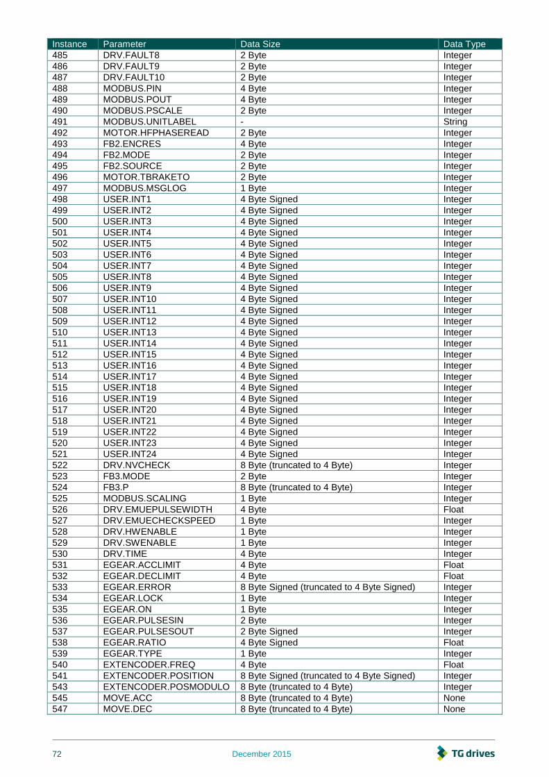
72 December 2015
Instance Parameter Data Size Data Type
485 DRV.FAULT8 2 Byte Integer
486 DRV.FAULT9 2 Byte Integer
487 DRV.FAULT10 2 Byte Integer
488 MODBUS.PIN 4 Byte Integer
489 MODBUS.POUT 4 Byte Integer
490 MODBUS.PSCALE 2 Byte Integer
491 MODBUS.UNITLABEL - String
492 MOTOR.HFPHASEREAD 2 Byte Integer
493 FB2.ENCRES 4 Byte Integer
494 FB2.MODE 2 Byte Integer
495 FB2.SOURCE 2 Byte Integer
496 MOTOR.TBRAKETO 2 Byte Integer
497 MODBUS.MSGLOG 1 Byte Integer
498 USER.INT1 4 Byte Signed Integer
499 USER.INT2 4 Byte Signed Integer
500 USER.INT3 4 Byte Signed Integer
501 USER.INT4 4 Byte Signed Integer
502 USER.INT5 4 Byte Signed Integer
503 USER.INT6 4 Byte Signed Integer
504 USER.INT7 4 Byte Signed Integer
505 USER.INT8 4 Byte Signed Integer
506 USER.INT9 4 Byte Signed Integer
507 USER.INT10 4 Byte Signed Integer
508 USER.INT11 4 Byte Signed Integer
509 USER.INT12 4 Byte Signed Integer
510 USER.INT13 4 Byte Signed Integer
511 USER.INT14 4 Byte Signed Integer
512 USER.INT15 4 Byte Signed Integer
513 USER.INT16 4 Byte Signed Integer
514 USER.INT17 4 Byte Signed Integer
515 USER.INT18 4 Byte Signed Integer
516 USER.INT19 4 Byte Signed Integer
517 USER.INT20 4 Byte Signed Integer
518 USER.INT21 4 Byte Signed Integer
519 USER.INT22 4 Byte Signed Integer
520 USER.INT23 4 Byte Signed Integer
521 USER.INT24 4 Byte Signed Integer
522 DRV.NVCHECK 8 Byte (truncated to 4 Byte) Integer
523 FB3.MODE 2 Byte Integer
524 FB3.P 8 Byte (truncated to 4 Byte) Integer
525 MODBUS.SCALING 1 Byte Integer
526 DRV.EMUEPULSEWIDTH 4 Byte Float
527 DRV.EMUECHECKSPEED 1 Byte Integer
528 DRV.HWENABLE 1 Byte Integer
529 DRV.SWENABLE 1 Byte Integer
530 DRV.TIME 4 Byte Integer
531 EGEAR.ACCLIMIT 4 Byte Float
532 EGEAR.DECLIMIT 4 Byte Float
533 EGEAR.ERROR 8 Byte Signed (truncated to 4 Byte Signed) Integer
534 EGEAR.LOCK 1 Byte Integer
535 EGEAR.ON 1 Byte Integer
536 EGEAR.PULSESIN 2 Byte Integer
537 EGEAR.PULSESOUT 2 Byte Signed Integer
538 EGEAR.RATIO 4 Byte Signed Float
539 EGEAR.TYPE 1 Byte Integer
540 EXTENCODER.FREQ 4 Byte Float
541 EXTENCODER.POSITION 8 Byte Signed (truncated to 4 Byte Signed) Integer
543 EXTENCODER.POSMODULO 8 Byte (truncated to 4 Byte) Integer
545 MOVE.ACC 8 Byte (truncated to 4 Byte) None
547 MOVE.DEC 8 Byte (truncated to 4 Byte) None
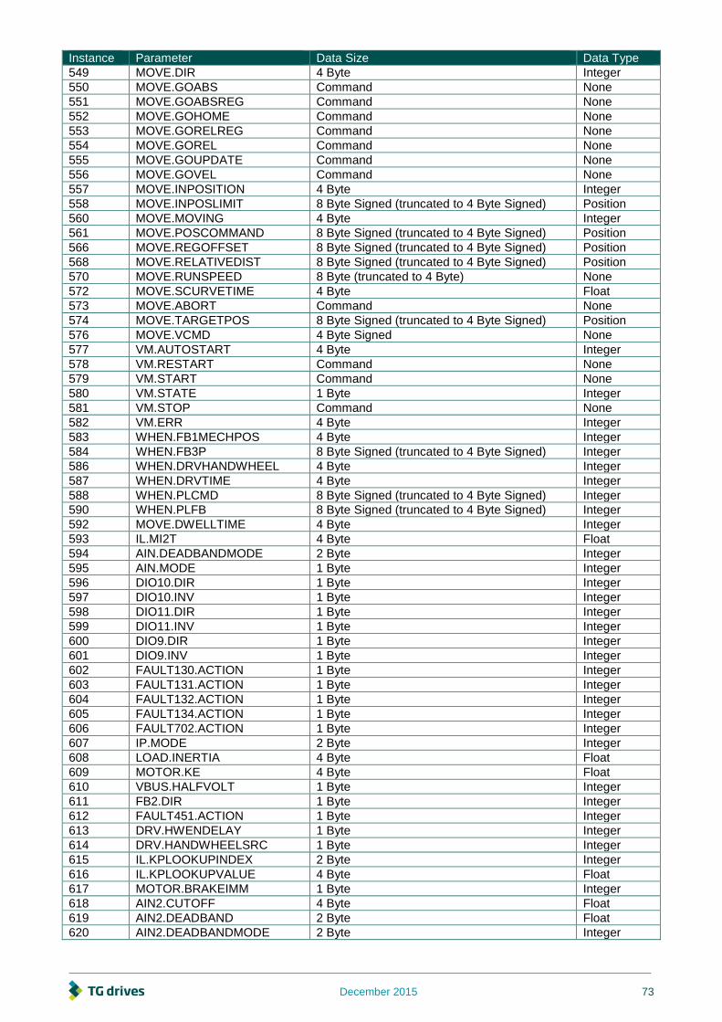
December 2015 73
Instance Parameter Data Size Data Type
549 MOVE.DIR 4 Byte Integer
550 MOVE.GOABS Command None
551 MOVE.GOABSREG Command None
552 MOVE.GOHOME Command None
553 MOVE.GORELREG Command None
554 MOVE.GOREL Command None
555 MOVE.GOUPDATE Command None
556 MOVE.GOVEL Command None
557 MOVE.INPOSITION 4 Byte Integer
558 MOVE.INPOSLIMIT 8 Byte Signed (truncated to 4 Byte Signed) Position
560 MOVE.MOVING 4 Byte Integer
561 MOVE.POSCOMMAND 8 Byte Signed (truncated to 4 Byte Signed) Position
566 MOVE.REGOFFSET 8 Byte Signed (truncated to 4 Byte Signed) Position
568 MOVE.RELATIVEDIST 8 Byte Signed (truncated to 4 Byte Signed) Position
570 MOVE.RUNSPEED 8 Byte (truncated to 4 Byte) None
572 MOVE.SCURVETIME 4 Byte Float
573 MOVE.ABORT Command None
574 MOVE.TARGETPOS 8 Byte Signed (truncated to 4 Byte Signed) Position
576 MOVE.VCMD 4 Byte Signed None
577 VM.AUTOSTART 4 Byte Integer
578 VM.RESTART Command None
579 VM.START Command None
580 VM.STATE 1 Byte Integer
581 VM.STOP Command None
582 VM.ERR 4 Byte Integer
583 WHEN.FB1MECHPOS 4 Byte Integer
584 WHEN.FB3P 8 Byte Signed (truncated to 4 Byte Signed) Integer
586 WHEN.DRVHANDWHEEL 4 Byte Integer
587 WHEN.DRVTIME 4 Byte Integer
588 WHEN.PLCMD 8 Byte Signed (truncated to 4 Byte Signed) Integer
590 WHEN.PLFB 8 Byte Signed (truncated to 4 Byte Signed) Integer
592 MOVE.DWELLTIME 4 Byte Integer
593 IL.MI2T 4 Byte Float
594 AIN.DEADBANDMODE 2 Byte Integer
595 AIN.MODE 1 Byte Integer
596 DIO10.DIR 1 Byte Integer
597 DIO10.INV 1 Byte Integer
598 DIO11.DIR 1 Byte Integer
599 DIO11.INV 1 Byte Integer
600 DIO9.DIR 1 Byte Integer
601 DIO9.INV 1 Byte Integer
602 FAULT130.ACTION 1 Byte Integer
603 FAULT131.ACTION 1 Byte Integer
604 FAULT132.ACTION 1 Byte Integer
605 FAULT134.ACTION 1 Byte Integer
606 FAULT702.ACTION 1 Byte Integer
607 IP.MODE 2 Byte Integer
608 LOAD.INERTIA 4 Byte Float
609 MOTOR.KE 4 Byte Float
610 VBUS.HALFVOLT 1 Byte Integer
611 FB2.DIR 1 Byte Integer
612 FAULT451.ACTION 1 Byte Integer
613 DRV.HWENDELAY 1 Byte Integer
614 DRV.HANDWHEELSRC 1 Byte Integer
615 IL.KPLOOKUPINDEX 2 Byte Integer
616 IL.KPLOOKUPVALUE 4 Byte Float
617 MOTOR.BRAKEIMM 1 Byte Integer
618 AIN2.CUTOFF 4 Byte Float
619 AIN2.DEADBAND 2 Byte Float
620 AIN2.DEADBANDMODE 2 Byte Integer
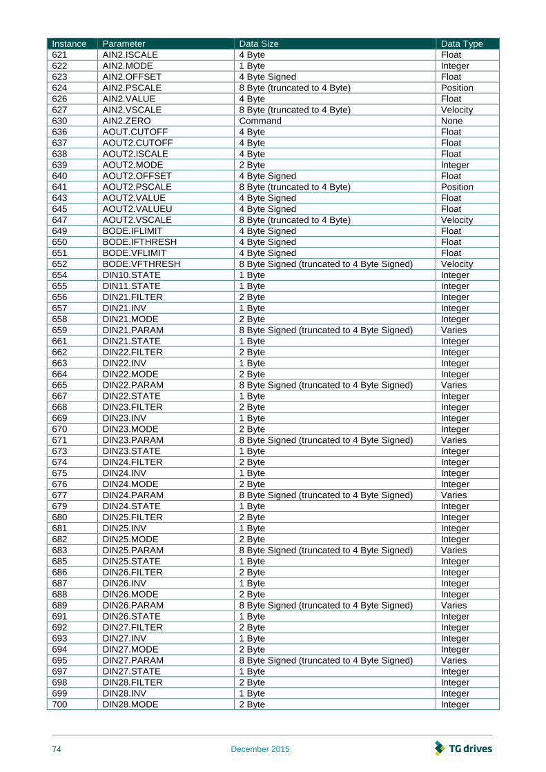
74 December 2015
Instance Parameter Data Size Data Type
621 AIN2.ISCALE 4 Byte Float
622 AIN2.MODE 1 Byte Integer
623 AIN2.OFFSET 4 Byte Signed Float
624 AIN2.PSCALE 8 Byte (truncated to 4 Byte) Position
626 AIN2.VALUE 4 Byte Float
627 AIN2.VSCALE 8 Byte (truncated to 4 Byte) Velocity
630 AIN2.ZERO Command None
636 AOUT.CUTOFF 4 Byte Float
637 AOUT2.CUTOFF 4 Byte Float
638 AOUT2.ISCALE 4 Byte Float
639 AOUT2.MODE 2 Byte Integer
640 AOUT2.OFFSET 4 Byte Signed Float
641 AOUT2.PSCALE 8 Byte (truncated to 4 Byte) Position
643 AOUT2.VALUE 4 Byte Signed Float
645 AOUT2.VALUEU 4 Byte Signed Float
647 AOUT2.VSCALE 8 Byte (truncated to 4 Byte) Velocity
649 BODE.IFLIMIT 4 Byte Signed Float
650 BODE.IFTHRESH 4 Byte Signed Float
651 BODE.VFLIMIT 4 Byte Signed Float
652 BODE.VFTHRESH 8 Byte Signed (truncated to 4 Byte Signed) Velocity
654 DIN10.STATE 1 Byte Integer
655 DIN11.STATE 1 Byte Integer
656 DIN21.FILTER 2 Byte Integer
657 DIN21.INV 1 Byte Integer
658 DIN21.MODE 2 Byte Integer
659 DIN21.PARAM 8 Byte Signed (truncated to 4 Byte Signed) Varies
661 DIN21.STATE 1 Byte Integer
662 DIN22.FILTER 2 Byte Integer
663 DIN22.INV 1 Byte Integer
664 DIN22.MODE 2 Byte Integer
665 DIN22.PARAM 8 Byte Signed (truncated to 4 Byte Signed) Varies
667 DIN22.STATE 1 Byte Integer
668 DIN23.FILTER 2 Byte Integer
669 DIN23.INV 1 Byte Integer
670 DIN23.MODE 2 Byte Integer
671 DIN23.PARAM 8 Byte Signed (truncated to 4 Byte Signed) Varies
673 DIN23.STATE 1 Byte Integer
674 DIN24.FILTER 2 Byte Integer
675 DIN24.INV 1 Byte Integer
676 DIN24.MODE 2 Byte Integer
677 DIN24.PARAM 8 Byte Signed (truncated to 4 Byte Signed) Varies
679 DIN24.STATE 1 Byte Integer
680 DIN25.FILTER 2 Byte Integer
681 DIN25.INV 1 Byte Integer
682 DIN25.MODE 2 Byte Integer
683 DIN25.PARAM 8 Byte Signed (truncated to 4 Byte Signed) Varies
685 DIN25.STATE 1 Byte Integer
686 DIN26.FILTER 2 Byte Integer
687 DIN26.INV 1 Byte Integer
688 DIN26.MODE 2 Byte Integer
689 DIN26.PARAM 8 Byte Signed (truncated to 4 Byte Signed) Varies
691 DIN26.STATE 1 Byte Integer
692 DIN27.FILTER 2 Byte Integer
693 DIN27.INV 1 Byte Integer
694 DIN27.MODE 2 Byte Integer
695 DIN27.PARAM 8 Byte Signed (truncated to 4 Byte Signed) Varies
697 DIN27.STATE 1 Byte Integer
698 DIN28.FILTER 2 Byte Integer
699 DIN28.INV 1 Byte Integer
700 DIN28.MODE 2 Byte Integer

December 2015 75
Instance Parameter Data Size Data Type
701 DIN28.PARAM 8 Byte Signed (truncated to 4 Byte Signed) Varies
703 DIN28.STATE 1 Byte Integer
704 DIN29.FILTER 2 Byte Integer
705 DIN29.INV 1 Byte Integer
706 DIN29.MODE 2 Byte Integer
707 DIN29.PARAM 8 Byte Signed (truncated to 4 Byte Signed) Varies
709 DIN29.STATE 1 Byte Integer
710 DIN30.FILTER 2 Byte Integer
711 DIN30.INV 1 Byte Integer
712 DIN30.MODE 2 Byte Integer
713 DIN30.PARAM 8 Byte Signed (truncated to 4 Byte Signed) Varies
715 DIN30.STATE 1 Byte Integer
716 DIN31.FILTER 2 Byte Integer
717 DIN31.INV 1 Byte Integer
718 DIN31.MODE 2 Byte Integer
719 DIN31.PARAM 8 Byte Signed (truncated to 4 Byte Signed) Varies
721 DIN31.STATE 1 Byte Integer
722 DIN32.FILTER 2 Byte Integer
723 DIN32.INV 1 Byte Integer
724 DIN32.MODE 2 Byte Integer
725 DIN32.PARAM 8 Byte Signed (truncated to 4 Byte Signed) Varies
727 DIN32.STATE 1 Byte Integer
728 DIN9.STATE 1 Byte Integer
729 DOUT10.STATE 1 Byte Integer
730 DOUT10.STATEU 1 Byte Integer
731 DOUT11.STATE 1 Byte Integer
732 DOUT11.STATEU 1 Byte Integer
733 DOUT21.MODE 1 Byte Integer
734 DOUT21.PARAM 4 Byte Signed Float
736 DOUT21.STATE 1 Byte Integer
737 DOUT21.STATEU 1 Byte Integer
738 DOUT22.MODE 1 Byte Integer
739 DOUT22.PARAM 4 Byte Signed Float
741 DOUT22.STATE 1 Byte Integer
742 DOUT22.STATEU 1 Byte Integer
743 DOUT23.MODE 1 Byte Integer
744 DOUT23.PARAM 4 Byte Signed Float
746 DOUT23.STATE 1 Byte Integer
747 DOUT23.STATEU 1 Byte Integer
748 DOUT24.MODE 1 Byte Integer
749 DOUT24.PARAM 4 Byte Signed Float
751 DOUT24.STATE 1 Byte Integer
752 DOUT24.STATEU 1 Byte Integer
753 DOUT25.MODE 1 Byte Integer
754 DOUT25.PARAM 4 Byte Signed Float
756 DOUT25.STATE 1 Byte Integer
757 DOUT25.STATEU 1 Byte Integer
758 DOUT26.MODE 1 Byte Integer
759 DOUT26.PARAM 4 Byte Signed Float
761 DOUT26.STATE 1 Byte Integer
762 DOUT26.STATEU 1 Byte Integer
763 DOUT27.MODE 1 Byte Integer
764 DOUT27.PARAM 4 Byte Signed Float
766 DOUT27.STATE 1 Byte Integer
767 DOUT27.STATEU 1 Byte Integer
768 DOUT28.MODE 1 Byte Integer
769 DOUT28.PARAM 4 Byte Signed Float
771 DOUT28.STATE 1 Byte Integer
772 DOUT28.STATEU 1 Byte Integer
773 DOUT29.MODE 1 Byte Integer

76 December 2015
Instance Parameter Data Size Data Type
774 DOUT29.PARAM 4 Byte Signed Float
776 DOUT29.STATE 1 Byte Integer
777 DOUT29.STATEU 1 Byte Integer
778 DOUT30.MODE 1 Byte Integer
779 DOUT30.PARAM 4 Byte Signed Float
781 DOUT30.STATE 1 Byte Integer
782 DOUT30.STATEU 1 Byte Integer
783 DOUT9.STATE 1 Byte Integer
784 DOUT9.STATEU 1 Byte Integer
785 DRV.BLINKDISPLAY Command None
786 DRV.CLRCRASHDUMP Command None
787 DRV.CMDDELAY 4 Byte Float
789 DRV.NVLOAD Command None
790 DRV.RUNTIME String
791 DRV.SETUPREQBITS 4 Byte Integer
792 DRV.WARNING1 4 Byte Integer
793 DRV.WARNING2 4 Byte Integer
794 DRV.WARNING3 4 Byte Integer
795 EIP.CONNECTED 1 Byte Integer
796 EIP.POSUNIT 4 Byte Integer
797 EIP.PROFUNIT 4 Byte Integer
798 FAULT139.ACTION 1 Byte Integer
803 FB1.CALTHRESH 8 Byte (truncated to 4 Byte) Integer
806 FB1.P 8 Byte Signed (truncated to 4 Byte Signed) Position
808 FB1.PDIR 1 Byte Integer
809 FB1.PIN 4 Byte Integer
810 FB1.POFFSET 8 Byte Signed (truncated to 4 Byte Signed) Position
812 FB1.POUT 4 Byte Integer
813 FB1.PUNIT 4 Byte Integer
814 FB1.USERBYTE 1 Byte Integer
815 FB1.USERDWORD 4 Byte Integer
816 FB1.USERWORD 2 Byte Integer
817 FB2.P 8 Byte Signed (truncated to 4 Byte Signed) Integer
819 FB2.PIN 4 Byte Integer
820 FB2.POFFSET 8 Byte Signed (truncated to 4 Byte Signed) Position
822 FB2.POUT 4 Byte Integer
823 FB2.PUNIT 4 Byte Integer
824 FB3.P 8 Byte Signed (truncated to 4 Byte Signed) Integer
826 FB3.PDIR 1 Byte Integer
827 FB3.PIN 4 Byte Integer
828 FB3.POFFSET 8 Byte Signed (truncated to 4 Byte Signed) Position
830 FB3.POUT 4 Byte Integer
831 FB3.PUNIT 4 Byte Integer
832 HOME.MAXDIST 8 Byte Signed (truncated to 4 Byte Signed) Position
834 IL.DIFOLD 4 Byte Float
835 IL.MI2TWTHRESH 1 Byte Integer
836 IL.MIMODE 1 Byte Integer
837 IP.RESET Command None
838 MOTOR.VOLTMIN 2 Byte Integer
839 MOTOR.VOLTRATED 2 Byte Integer
840 MOTOR.VRATED 4 Byte Signed Float
843 SD.LOAD Command None
844 SD.SAVE Command None
845 SD.STATUS 1 Byte Integer
846 VL.FBUNFILTERED 8 Byte Signed (truncated to 4 Byte Signed) Velocity
848 WS.DISARM Command None
849 WS.FREQ 4 Byte Float
850 WS.TDELAY4 2 Byte Integer
851 WS.CHECKT 2 Byte Integer
852 WS.CHECKV 8 Byte Signed (truncated to 4 Byte Signed) Velocity

December 2015 77
Instance Parameter Data Size Data Type
859 AOUT.VSCALE 8 Byte (truncated to 4 Byte) Velocity
861 WS.TSTANDSTILL 2 Byte Integer
862 WS.TIRAMP 2 Byte Integer
863 FB1.PMTSAVEEN 1 Byte None
864 FB1.PMTBITS 1 Byte None
865 MOTOR.IMTR 2 Byte Integer
866 IL.FBSOURCE 1 Byte Integer
867 MOTOR.IMID 4 Byte Float
868 WS.CHECKMODE 1 Byte Integer
869 REGEN.POWERFILTERED 8 Byte (truncated to 4 Byte) Integer
8192 VBUS.VALUE 2 Byte Integer
8193 STATUS3 1 Byte Integer
8195 DIN.STATES 1 Byte Integer
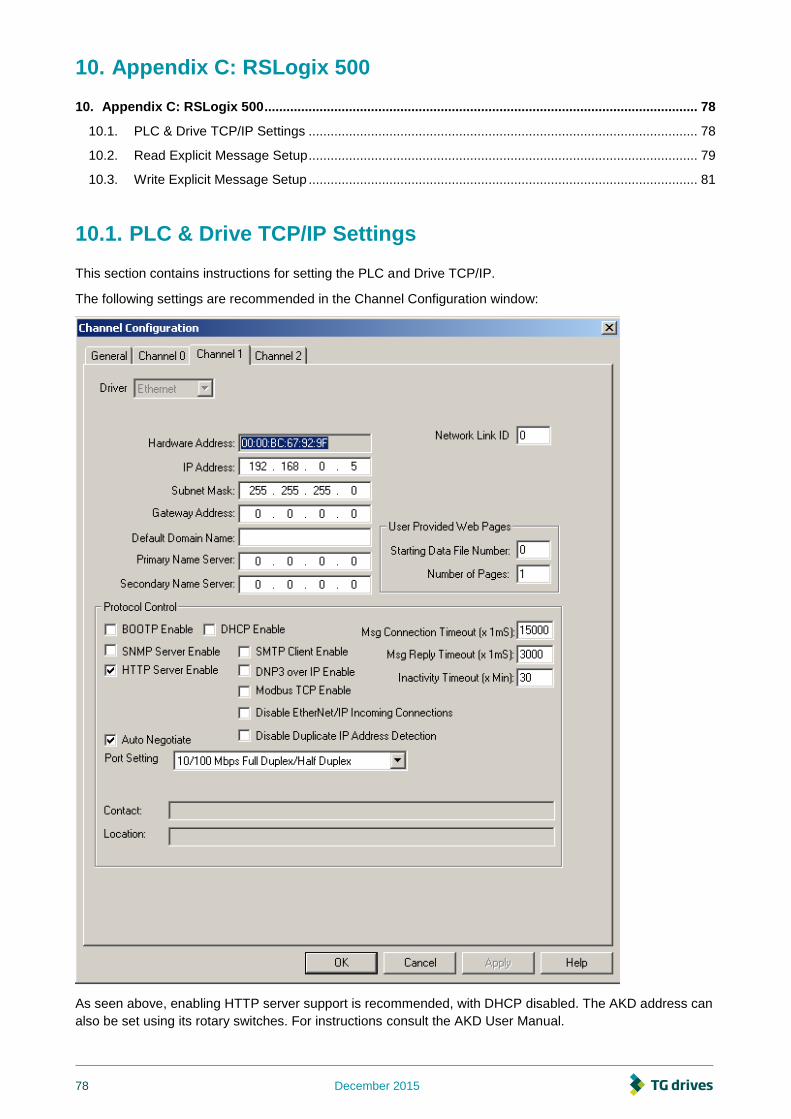
78 December 2015
10. Appendix C: RSLogix 500
10. Appendix C: RSLogix 500 ...................................................................................................................... 78
10.1. PLC & Drive TCP/IP Settings .......................................................................................................... 78
10.2. Read Explicit Message Setup .......................................................................................................... 79
10.3. Write Explicit Message Setup .......................................................................................................... 81
10.1. PLC & Drive TCP/IP Settings
This section contains instructions for setting the PLC and Drive TCP/IP.
The following settings are recommended in the Channel Configuration window:
As seen above, enabling HTTP server support is recommended, with DHCP disabled. The AKD address can
also be set using its rotary switches. For instructions consult the AKD User Manual.

December 2015 79
10.2. Read Explicit Message Setup
Displayed below is an example of a read ladder rung. The timer limits the read to every 50 ms.
To setup a read explicit message, first create a MSG instruction, and set it to the following settings:

80 December 2015
Next click on the MultiHop tab and enter the drive's IP address as seen below:
For 8 byte messages use two LONG data files (enter one and RSLogix will automatically use the second).

December 2015 81
10.3. Write Explicit Message Setup
Displayed below is an example of a command write ladder. The "one shot" is to prevent the instruction from
continuously writing to the parameter (commands don't require data but RSLogix 500 does require a data
table address. The act of writing to the command parameter will trigger a response).
The following is an example of a 8 byte write ladder. The “one shot” is to prevent the instruction from
continuously writing to the parameter. In this case, the drive parameter is 8 bytes so the data to be written is
in L9:0 (LSB) & L9:1 (MSB).
To setup a write explicit message, first create a MSG instruction, and set it to the following settings:

82 December 2015
Then click on the MultiHop tab and enter the drive's IP address as seen below: