akg 4 -ex - steven engineering
TRANSCRIPT

Module no:0421061 LabelId:0421061 Operator:Phoenix 09:16:27, Mittwoch, 1. März 2000
AKG 4 ... -EX
Terminal width 7
(IEC)
[mm2]
Connection data
EN 50 019 *
rigid
solid
0.5-6
0.5-6
flexible
stranded
0.5-4
0.5-4
AWG
20-10
–
I
[A]
41
39/30
* Certificate no.: PTB Ex-92.C.3102U
E PTB
Description
N/PE/L connectingterminal block,with insulating cap:
blue
green-yellow
black
(for N)
(for PE)
(for L1, L2, L3)
Type
AKG 4 BU-EX
AKG 4 GNYE-EX
AKG 4 BK-EX
Order No.
04 21 06 1
04 21 04 5
04 21 05 8
Pcs. Pkt.
50
50
50
Accessories
(1) Neutral busbar, 3 x 10 mm, 1 mlong copper, tin-plated
(2) Support, insulating material with 2retaining screws, optionally applicablefor busbars 3 x 10 mm or 6 x 6 mm
(3) Zack strip,10-section, white
NLS-CU 3/10
AB/SS-EX
ZB 6 (see info)
04 02 17 4
04 04 41 5
10
10
Technical data
Dimensions
Technical data in accordance with IEC 60 947-7-1
Maximum load current / cross section
Current carrying capacity of the N busbar
Connection capacity
Stranded with ferrule without / with plasticsleeve
Multi-conductor connection (2 conductors with samecross section)
Solid / stranded
Stranded with ferrule without plastic sleeve
Stranded with TWIN ferrule with plastic
[A] / [mm2]
[A]
[mm2]
[mm2]
[mm2]
[mm2]
see description drawing
41 / 6
140
0.5 - 6 / 0.5 - 6
0.5 - 2.5 / 0.5 - 2.5
0.5 - 2.5
0.5 - 2.5
Phoenix Contact Elektronischer Katalog Page 1 / 2

Module no:0421061 LabelId:0421061 Operator:Phoenix 09:16:27, Mittwoch, 1. März 2000p
sleeve
Stripping length
Internal cylindrical gage (IEC 60947-1:1988)
Thread
Torque
Insulation material
Inflammability class acc. to UL 94
Temp. indices RTI acc. to UL 746 B / Ti acc. to IEC 60216-1
Installation temperature range / temperatureclass
[mm ]
[mm]
[Nm]
[°C] / –
16
A 4
M 4
1.5 - 1.8
PA
V2
125 / 100
-40...+80 / T6
Dimensional drawing
Circuit diagram
Phoenix Contact Elektronischer Katalog Page 2 / 2

Module no:2703172 LabelId:2703172 Operator:Phoenix 12:32:47, Mittwoch, 1. März 2000
G 5/...-EX
(IEC)
[mm2]
IEC 60 947-7-1
EN 50 019 *
rigid
solid
0.2-4
0.2-4
flexible
stranded
0.2-4
0.2-4
AWG
24-12
–
I
[A]
32
21
U
[V]
500
275
* Certificate no.: BAS Ex 89C3087U
H BASEEFA
Description
Equipment terminal block,for direct mounting
No. of positions
3
4
6
12
Type
G 5/3-EX
G 5/4-EX
G 5/6-EX
G 5/12-EX
Order No.
27 03 17 2
27 03 18 5
27 03 19 8
27 03 20 8
Pcs. Pkt.
50
50
50
50
Accessories
(1) Marker pin, plastic
unprinted: for labeling with markerpen
printed: with 1, 2 or 3 characters,white
BN WH:… (see info)
BNB WH…1) 14 01 41 7
100
100
Technical data
Dimensions
Technical data in accordance with IEC 60 947-7-1
Maximum load current / cross section
Rated surge voltage / contamination class
Surge voltage category / insulationmaterial group
Connection capacity
Stranded with ferrule without / with plasticsleeve
Multi-conductor connection (2 conductors with samecross section)
Solid / stranded
Stranded with ferrule without plastic sleeve
Stranded with TWIN ferrule with plasticsleeve
Stripping length
[A] / [mm2]
[kV] / –
– / –
[mm2]
[mm2]
[mm2]
[mm2]
[mm]
see description drawing
32 / 4
6 / 3
III / I
0.25 - 4 / 0.25 - 2.5
0.2 - 1.5 / 0.2 - 1.5
0.25 - 1.5
0.5 - 1.0
8
Phoenix Contact Elektronischer Katalog Page 1 / 2

Module no:2703172 LabelId:2703172 Operator:Phoenix 12:32:47, Mittwoch, 1. März 2000
Internal cylindrical gage (IEC 60 947-1:1988)
Thread
Torque
Insulation material
Inflammability class acc. to UL 94
Temperature indices RTI acc. to UL 746 B / Ti acc. to IEC60 216-1
Installation temperature range /temperature class
[Nm]
[°C] / –
A 3
M 3
0.6 - 0.8
PA
V2
125 / 100
-25...+80 / T6
1) Required marking is to be specified.
Technical Data
Type
G 5/3
G 5/4
G 5/6
G 5/12
a
31
38
52
92
b
11
18
32
72.5
Important Ex note:All clamping screws must be tightened.
Dimensional drawing
Phoenix Contact Elektronischer Katalog Page 2 / 2
Module no:0501059 LabelId:0501059 Operator:Phoenix 09:20:26, Mittwoch, 1. März 2000
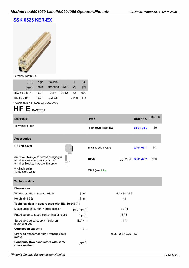
SSK 0525 KER-EX
Terminal width 6.4
(IEC)
[mm2]
IEC 60 947-7-1
EN 50 019 *
rigid
solid
0.2-4
0.2-4
flexible
stranded
0.2-4
0.2-2.5
AWG
24-12
–
I
[A]
32
21/15
U
[V]
690
418
* Certificate no.: BAS Ex 90C3200U
HFE BASEEFA
Description
Terminal block
Type
SSK 0525 KER-EX
Order No.
05 01 05 9
Pcs. Pkt.
50
Accessories
(1) End cover
(3) Chain bridge, for cross bridging interminal center across any no. ofterminal blocks, 1-pos. with screw
(4) Zack strip,10-section, white
D-SSK 0525 KER
KB-6
ZB 6 (see info)
Imax.: 29 A
02 01 06 1
02 01 47 2
50
100
Technical data
Dimensions
Width / length / end cover width
Height (NS 32)
Technical data in accordance with IEC 60 947-7-1
Maximum load current / cross section
Rated surge voltage / contamination class
Surge voltage category / insulationmaterial group
Connection capacity
Stranded with ferrule with / without plasticsleeve
Continuity (two conductors with samecross section)
[mm]
[mm]
[A] / [mm2]
[mm2]
[kV] / –
– / –
[mm2]
6.4 / 38 / 4.2
48
32 / 4
8 / 3
III / I
0.25 - 2.5 / 0.25 - 1.5
Phoenix Contact Elektronischer Katalog Page 1 / 2
Module no:0501059 LabelId:0501059 Operator:Phoenix 09:20:26, Mittwoch, 1. März 2000
Solid / stranded
Stranded with ferrule without plastic sleeve
Stranded with TWIN ferrule with plasticsleeve
Stripping length
Internal cylindrical gage (IEC 60947-1:1988)
Thread
Torque
Insulation material
Thermal stability
Installation temperature range /temperature class
[mm2]
[mm2]
[mm2]
[mm]
[Nm]
[°C] / –
0.2 - 1.5 / 0.2 - 1.5
0.25 - 1.5
0.5 - 1.5
9
A 3
M 3
0.6 - 0.8
ceramics
220 (1000)
-40...+200 / T6
Note:Ground terminal blocks without insulation housing available on request!Important Ex note:If these elements are mixed with other series and sizes and if other accessories are used, the required air and creepagedistances must be complied with.Important Ex notes:All clamping screws must be tightened.If the bridges are used, a cover is necessary between bridges which make direct contact, as well as at the beginningand end of each bridge.
Phoenix Contact Elektronischer Katalog Page 2 / 2

Module no:0502058 LabelId:0502058 Operator:Phoenix 09:21:33, Mittwoch, 1. März 2000
SSK 110 KER-EX
Terminal width 8.4
(IEC)
[mm2]
IEC 60 947-7-1
EN 50 019 *
rigid
solid
0.5-10
0.5-10
flexible
stranded
0.5-6
0.5-6
AWG
20-8
–
I
[A]
57
53/37
U
[V]
800
418
* Certificate no.: PTB Ex-85.B.3136U
HFE PTB
Description
Terminal block
Type
SSK 110 KER-EX
Order No.
05 02 05 8
Pcs. Pkt.
50
Accessories
(1) End cover
(3) Chain bridge, for cross bridging interminal center across any no. ofterminal blocks, 1-pos. with screw
(4) Zack strip,10-section, white
D-SSK 110 KER
KB-8
ZB 8 (see info)
Imax.: 50 A
02 02 06 0
02 02 20 6
50
100
Technical data
Dimensions
Width / length / end cover width
Height (NS 32)
Technical data in accordance with IEC 60 947-7-1
Maximum load current / cross section
Rated surge voltage / contamination class
Surge voltage category / insulationmaterial group
Connection capacity
Stranded with ferrule with / without plasticsleeve
[mm]
[mm]
[A] / [mm2]
[mm2]
[kV] / –
– / –
8.4 / 38 / 4.2
51
57 / 10
8 / 3
III / I
0.5 - 6 / 0.5 - 4
Phoenix Contact Elektronischer Katalog Page 1 / 2

Module no:0502058 LabelId:0502058 Operator:Phoenix 09:21:33, Mittwoch, 1. März 2000
Continuity (two conductors with samecross section)
Solid / stranded
Stranded with ferrule without plastic sleeve
Stranded with TWIN ferrule with plasticsleeve
Stripping length
Internal cylindrical gage (IEC 60947-1:1988)
Thread
Torque
Insulation material
Thermal stability
Installation temperature range /temperature class
[mm2]
[mm2]
[mm2]
[mm2]
[mm]
[Nm]
[°C] / –
0.5 - 2.5 / 0.5 - 2.5
0.5 - 2.5
0.5 - 2.5
10
A 4
M 4
1.5 - 1.8
ceramics
220 (1000)
-40...+200 / T6
Note:Ground terminal blocks without insulation housing available on request!Important Ex note:If these elements are mixed with other series and sizes and if other accessories are used, the required air and creepagedistances must be complied with.Important Ex notes:All clamping screws must be tightened.If the bridges are used, a cover is necessary between bridges which make direct contact, as well as at the beginningand end of each bridge.
Phoenix Contact Elektronischer Katalog Page 2 / 2

Module no:0503057 LabelId:0503057 Operator:Phoenix 09:22:39, Mittwoch, 1. März 2000
SSK 116 KER-EX
Terminal width 10.4
(IEC)
[mm2]
IEC 60 947-7-1
EN 50 019 *
rigid
solid
0.5-16
0.5-16
flexible
stranded
0.5-10
0.5-10
AWG
20-6
–
I
[A]
76
72/53
U
[V]
800
418
* Certificate no.: PTB Ex-85.B.3135U
HFE PTB/TUEV A
Description
Terminal block
Type
SSK 116 KER-EX
Order No.
05 03 05 7
Pcs. Pkt.
50
Accessories
(1) End cover
(3) Chain bridge, for cross bridging interminal center across any no. ofterminal blocks, 1-pos. with screw
(4) Zack strip,10-section, white
D-SSK 116 KER
KB-10
ZB 10 (see info)
Imax.: 70 A
02 03 06 9
02 03 20 5
50
100
Technical data
Dimensions
Width / length / end cover width
Height (NS 32)
Technical data in accordance with IEC 60 947-7-1
Maximum load current / cross section
Rated surge voltage / contamination class
Surge voltage category / insulation materialgroup
Connection capacity
Stranded with ferrule with / without plasticsleeve
Continuity (two conductors with samecross section)
[mm]
[mm]
[A] / [mm2]
[mm2]
[kV] / –
– / –
[mm2]
10.4 / 38 / 4.2
55
76 / 16
8 / 3
III / I
0.5 - 10 / 0.5 - 6
Phoenix Contact Elektronischer Katalog Page 1 / 2

Module no:0503057 LabelId:0503057 Operator:Phoenix 09:22:39, Mittwoch, 1. März 2000
Solid / stranded
Stranded with ferrule without plastic sleeve
Stranded with TWIN ferrule with plastic sleeve
Stripping length
Internal cylindrical gage (IEC 60947-1:1988)
Thread
Torque
Insulation material
Thermal stability
Installation temperature range / temperatureclass
[mm2]
[mm2]
[mm2]
[mm]
[Nm]
[°C] / –
0.5 - 4 / 0.5 - 4
0.5 - 4
0.5 - 6
11
B 6
M 4
1.5 - 1.8
ceramics
220 (1000)
-40...+200 / T6
Note:Ground terminal blocks without insulation housing available on request!Important Ex note:If these elements are mixed with other series and sizes and if other accessories are used, the required air and creepagedistances must be complied with.Important Ex notes:All clamping screws must be tightened.If the bridges are used, a cover is necessary between bridges which make direct contact, as well as at the beginningand end of each bridge.
Phoenix Contact Elektronischer Katalog Page 2 / 2

Module no:0704076 LabelId:0704076 Operator:Phoenix 10:00:07, Mittwoch, 1. März 2000
UHSK/S 2000
Terminal width 10.2
(IEC)
[mm2]
IEC 60 947-7-1
EN 50 019 *
rigid
solid
0.5-10
0.5-6
flexible
stranded
0.5-6
0.5-6
AWG
20-8
–
I
[A]
57
–
U
[V]
2000
1100
* Certificate no.: BVS Nr. 89.B.1083U, EEx e IDMT-BVS/KDB
Description
Terminal block
Type
UHSK/S 2000
Order No.
07 04 07 6
Pcs. Pkt.
50
Accessories
(1) End cover
(3) Chain bridge, for cross bridging interminal center across any no. ofterminal blocks, 1-pos. with screw
(4) Zack strip,10-section, white
D-UHSK 2000
FB 10-10-EX
ZB 10 (see info)
Imax.: 41 A
07 04 02 1
02 03 24 7
50
10
Technical data
Dimensions
Width / length / end cover width
Height (NS 35:7.5 / NS 35:15 / NS 32)
Technical data in accordance with IEC 60 947-7-1
Maximum load current / cross section
Rated surge voltage / contamination class
Surge voltage category / insulation materialgroup
Connection capacity
Stranded with ferrule with / without plasticsleeve
Continuity (two conductors with samecross section)
Solid / stranded
Stranded with ferrule without plastic sleeve
St d d ith TWIN f l ith l ti l
[mm]
[mm]
[A] / [mm2]
[mm2]
[kV] / –
– / –
[mm2]
[mm2]2
10.2 / 52 / 2.0
70.5 / 78 / 75.5
57 / 10
121) / 3
III / I
0.5 - 10 / 0.5 - 6
0.5 - 6 / 0.5 - 6
0.5 - 6
0 5 6Phoenix Contact Elektronischer Katalog Page 1 / 2

Module no:0704076 LabelId:0704076 Operator:Phoenix 10:00:07, Mittwoch, 1. März 2000Stranded with TWIN ferrule with plastic sleeve
Stripping length
Internal cylindrical gage (IEC 60947-1:1988)
Thread
Torque
Insulation material
Inflammability class acc. to UL 94
Temp. indices RTI acc. to UL 746 B / Ti acc. to IEC 60216-1
Installation temperature range / temperatureclass
[mm2]
[mm2]
[mm]
[Nm]
[°C] / –
0.5 - 6
15
A 5
M 4
1.5 - 1.8
PA
V2
125 / 100
-40...+90 / T6 (T5)
1) extrapolatedNote:Ground terminal blocks without insulation housing available on request!Important Ex note:If these elements are mixed with other series and sizes and if other accessories are used, the required air and creepagedistances must be complied with.Important Ex note:The notched partition plate must first be removed to bridge the UHSK/S 2000.
Block diagram
UHSK/S 2000
Phoenix Contact Elektronischer Katalog Page 2 / 2

Module no:1414051 LabelId:1414051 Operator:Phoenix 11:00:12, Mittwoch, 1. März 2000
MBK 2,5/E-EX
Terminal width 5.2
(IEC)
[mm2]
IEC 60 947-7-1
EN 50 019 *
rigid
solid
0.2-2.5
0.2-2.5
flexible
stranded
0.2-2.5
0.2-2.5
AWG
24-14
–
I
[A]
24
15
U
[V]
250
66
* Certificate no.: BAS Ex 91C3105U
H BASEEFA
Description
Terminal block, for mounting on NS 15,acc. to EN 50 045
Color
gray
Type
MBK 2,5/E-EX
Order No.
14 14 05 1
Pcs. Pkt.
50
Accessories
(1) End cover,can also be used aspartition plate
(2) Partition plate, prescribed forelectr. separation of adjacent bridgesor terminal block groups, 2.5 mm thick
(3) Fixed bridges, for cross bridging interminal center, 10-pos., divisible with10 screws and 10 spring washers
(4) Insertion bridge, fullyinsulated,2-pos.
fully insulated, 3-pos.
insulated spine, divisible, 10-pos.
(5) Marker pin, plastic,
unprinted: for labeling with markerpen,
printed: with 1, 2 or 3 characters,white
gray D-MBK 2,5/E
ATP-MBK
FBRN 10-5-EX
EB 2-5
EB 3-5
EB 10-5
BN WH:… (see info)
BNB WH:…1)
Imax.: 23 A
Imax.: 20 A
20 A
20 A
14 14 03 5
14 13 22 7
30 00 61 2
14 01 15 8
14 01 14 5
14 01 13 2
14 01 41 7
50
50
10
100
100
10
100
Technical data
Dimensions
Width / length / end cover width
Height (NS 15)
Technical data in accordance with IEC 60 947-7-1
Maximum load current / cross section
[mm]
[mm]
[A] / [mm2]
5.2 / 24.5 / 1
26.5
24 / 2.5
Phoenix Contact Elektronischer Katalog Page 1 / 2

Module no:1414051 LabelId:1414051 Operator:Phoenix 11:00:12, Mittwoch, 1. März 2000
Max. cross section with insertion bridge(solid/stranded)
Rated surge voltage / contamination class
Surge voltage category / insulation materialgroup
Connection capacity
Stranded with ferrule without / with plasticsleeve
Multi conductor connection (2 conductors with samecross section)
Solid / stranded
Stranded with ferrule without plastic sleeve
Stranded with TWIN ferrule with plastic sleeve
Stripping length
Internal cylindrical gage (IEC 60 947-1:1988)
Thread
Torque
Insulation material
Inflammability class acc. to UL 94
Temperature indices RTI acc. to UL 746 B / Ti acc. to IEC60 216-1
Installation temperature range / temperatureclass
[mm2]
[kV] / –
– / –
[mm2]
[mm2]
[mm2]
[mm2]
[mm]
[Nm]
[°C] / –
2.5 / 2.5
4 / 3
III / I
0.25 - 2.5 / 0.25 - 2.5
0.2 - 0.75 / 0.2 - 0.75
0.25 - 0.75
0.5 - 1.5
7
A 3
M 3
0.6 - 0.8
PA
V2
125 / 100
-40...+70 / T6
1) Required marking is to be specified.Important Ex notes:All terminal screws must be tightened.If the fixed bridges and chain bridges are used, a partition plate is necessary between bridges which make directcontact, and a cover is required at the beginning and end of each bridge (see sketches).Accordingly, equipotential bondings that were created with insertion bridges must be separated by means of partitionplates (see sketches).If these elements are mixed with other series and sizes and if other accessories are used, the required air and creepagedistances must be complied with.
Block diagram
Phoenix Contact Elektronischer Katalog Page 2 / 2

Module no:0561002 LabelId:0561002 Operator:Phoenix 09:31:23, Mittwoch, 1. März 2000
MXK 4
Terminal width 6.2
(IEC)
[mm2]
IEC 60 947-7-1
EN 50 019 *
rigid
solid
0.2-4
0.2-4
flexible
stranded
0.2-4
0.2-4
AWG
24-12
–
I
[A]
32
27
U
[V]
690
420
* Certificate no.: PTB Ex-94.C.3152UBVS Ex-89.B.1082U, EEx e I
HE PTB/DMT-BVS/NV/BKI
Description
Terminal block, for mounting on NS 15,acc. to EN 50 045
Color
gray
blue
Type
MXK 4
MXK 4 BU
Order No.
05 61 00 2
05 61 02 8
Pcs. Pkt.
50
50
Accessories
(1) End cover,can also be used aspartition plate
(3) Fixed bridges, for cross bridging interminal center, 10-pos., divisible with10 screws and 10 spring washers
(5) Marker pin, plastic,
unprinted: for labeling with markerpen,
printed: with 1, 2 or 3 characters,white
gray
blue
D-MXK 4
D-MXK 4 BU PA 6.6
FB 10-6-EX
BN WH:… (see info)
BNB WH:…1)
Imax.: 27 A
05 61 01 5
05 61 03 1
02 01 28 1
14 01 41 7
50
50
10
100
Technical data
Dimensions
Width / length / end cover width
Height (NS 15)
Technical data in accordance with IEC 60 947-7-1
Maximum load current / cross section
Rated surge voltage / contamination class
Surge voltage category / insulation materialgroup
Connection capacity
Stranded with ferrule without / with plastic
[mm]
[mm]
[A] / [mm2]
[kV] / –
– / –
[mm2]
6.2 / 28 / 1.5
38
32 / 4
8 / 3
III / I
0.25 - 2.5 / 0.25 - 2.5
Phoenix Contact Elektronischer Katalog Page 1 / 2

Module no:0561002 LabelId:0561002 Operator:Phoenix 09:31:23, Mittwoch, 1. März 2000p
sleeve
Multi conductor connection (2 conductors with samecross section)
Solid / stranded
Stranded with ferrule without plastic sleeve
Stranded with TWIN ferrule with plasticsleeve
Stripping length
Internal cylindrical gage (IEC 60947-1:1988)
Thread
Torque
Insulation material
Inflammability class acc. to UL 94
Temperature indices RTI acc. to UL 746 B / Ti acc. toIEC 60 216-1
Installation temperature range / temperatureclass
[mm ]
[mm2]
[mm2]
[mm2]
[mm]
[Nm]
[°C] / –
0.2 - 1.5 / 0.2 - 1.5
0.25 - 1.5
0.5 - 1.5
8
A 3
M 3
0.6 - 0.8
PA
V0
130 / 120
-40...+80 / T6
1) Required marking is to be specified.Important Ex notes:All terminal screws must be tightened.If the fixed bridges and chain bridges are used, a partition plate is necessary between bridges which make directcontact, and a cover is required at the beginning and end of each bridge (see sketches).Accordingly, equipotential bondings that were created with insertion bridges must be separated by means of partitionplates (see sketches).If these elements are mixed with other series and sizes and if other accessories are used, the required air and creepagedistances must be complied with.
Block diagram
Phoenix Contact Elektronischer Katalog Page 2 / 2

Module no:0562030 LabelId:0562030 Operator:Phoenix 09:31:30, Mittwoch, 1. März 2000
MXK 5 KRI-EX
Terminal width 8.2
(IEC)
[mm2]
IEC 60 947-7-1
EN 50 019 *
rigid
solid
0.2-4
0.2-4
flexible
stranded
0.2-4
0.2-4
AWG
24-12
–
I
[A]
32
30
U
[V]
800
726
* Certificate no.: PTB Ex-92.C.3143U
H PTB/NV
Description
Terminal block, for mounting on NS 15,acc. to EN 50 045
Color
gray
Type
MXK 5 KRI-EX
Order No.
05 62 03 0
Pcs. Pkt.
50
Accessories
(1) End cover,can also be used aspartition plate
(2) Partition plate, prescribed forelectr. separation of adjacent bridgesor terminal block groups, 2.5 mm thick
(3) Fixed bridges, for cross bridging interminal center, 10-pos., divisible with10 screws and 10 spring washers
(5) Marker pin, plastic,
unprinted: for labeling with markerpen,
printed: with 1, 2 or 3 characters,white
gray closed housing
no end cover
TP-MXK 5
FB 10-8/MXK 5
BN WH:… (see info)
BNB WH:…1)
Imax. : 33 A
05 62 79 7
05 62 18 2
14 01 41 7
50
10
100
Technical data
Dimensions
Width / length / end cover width
Height (NS 15)
Technical data in accordance with IEC 60 947-7-1
Maximum load current / cross section
Rated surge voltage / contamination class
Surge voltage category / insulation materialgroup
[mm]
[mm]
[A] / [mm2]
[kV] / –
– / –
8.2 / 28.5 / –
33.5
32 / 4
8 / 3
III / I
Phoenix Contact Elektronischer Katalog Page 1 / 2

Module no:0562030 LabelId:0562030 Operator:Phoenix 09:31:30, Mittwoch, 1. März 2000g
Connection capacity
Stranded with ferrule without / with plasticsleeve
Multi conductor connection (2 conductors with samecross section)
Solid / stranded
Stranded with ferrule without plastic sleeve
Stranded with TWIN ferrule with plasticsleeve
Stripping length
Internal cylindrical gage (IEC 60947-1:1988)
Thread
Torque
Insulation material
Inflammability class acc. to UL 94
Temperature indices RTI acc. to UL 746 B / Ti acc. toIEC 60 216-1
Installation temperature range / temperatureclass
[mm2]
[mm2]
[mm2]
[mm2]
[mm]
[Nm]
[°C] / –
0.25 - 4 / 0.25 - 2.5
0.2 - 1.5 / 0.2 - 1.5
0.25 - 1.5
0.5 - 1
8
A 3
M 3
0.6 - 0.8
Melamin FM
V0
130 / 135
-40...+92 / T6 (T5)
1) Required marking is to be specified.Important Ex notes:All terminal screws must be tightened.If the fixed bridges and chain bridges are used, a partition plate is necessary between bridges which make directcontact, and a cover is required at the beginning and end of each bridge (see sketches).Accordingly, equipotential bondings that were created with insertion bridges must be separated by means of partitionplates (see sketches).If these elements are mixed with other series and sizes and if other accessories are used, the required air and creepagedistances must be complied with.
Block diagram
Phoenix Contact Elektronischer Katalog Page 2 / 2

Module no:1870255 LabelId:1870255 Operator:Phoenix 12:11:47, Mittwoch, 1. März 2000
MK3DSMH 3
High double level terminal block with offset levelsPitch 5.08
(IEC)
[mm2]
Connection data
EN 50019 *
rigid
solid
0.2-4
0.2-4
flexible
stranded
0.2-2.5
0.2-2.5
AWG
24-12
–
I
[A]
24
24/19
U
[V]
250
66
* Certificate no.: BVS 97.D.7001UDMT-BVS
Description
Printed circuit screw termination blocks,5.08 mm pitch, with housing interlocking,color: green
No. ofpositions
2
3
Type
MK3DSMH 3/2-5,08-EX
MK3DSMH 3/3-5,08-EX
Order No.
18 70 25 5
18 70 26 8
Pcs. Pkt.
50
50
Accessories
(1) Single cover, to cover theindividual terminal positions, snapfitting, color: orange, transparent
(2) Screwdriver,blade: 0.6 x 3.5 x 100 mm,length: 180 mm
(3) Marker card, with 12 pcs.,10-section marker strips, white,self-adhesive, for 120 terminal blocks
EA-MKDS
SZS 0,6 x 3,5
SK 5/3,8(see info)
17 11 40 8
12 05 05 3
1
10
Technical data
Dimensions
Pitch
Hole diameter
Pin dimensions
Technical data in accordance with IEC 60 999/ DINVDE 0110
Insulation material group
Surge voltage category / contamination class
Rated voltage
Rated surge voltage
Nominal current / cross section
Maximum load current / crosssection
Connection capacity
Solid / stranded / conductor sizes
[A] / [mm2]
[A] / [mm2]
[mm2] / [mm2] /AWG
[mm]
[mm]
[mm]
–
– / –
[V]
[kV]
see description
5.08
1.3
0.9 x 0.9
I
III / 3
250
4
22 / 2.5
24 / 4
0.2 - 4 / 0.2 - 2.5 / 24 -12
III / 2
320
4
II / 2
630
4
Phoenix Contact Elektronischer Katalog Page 1 / 3

Module no:1870255 LabelId:1870255 Operator:Phoenix 12:11:47, Mittwoch, 1. März 2000
Stranded with ferrules without / with plasticcollar
Multi-conductor connection (2 conductors with samecross section)
Solid / stranded
Stranded with ferrule without plastic sleeve
Stranded with TWIN ferrule with plasticsleeve
Stripping length
Internal cylindrical gage (IEC 60947-1:1988)
Thread
Torque
Insulation material
Inflammability class acc. to UL 94
Temperature indices RTI acc. to UL 746 B / Ti acc. toIEC 60 216-1
Installation temperature range / temperatureclass
[mm2]
[mm2]
[mm2]
[mm2]
[mm]
–
–
[Nm]
[°C] / –
0.25 - 2.5 / 0.25 - 2.5
0.2 - 1.5 / 0.2 - 1.5
0.25 - 0.75
0.5 - 1.5* / 0.5**
8
A 3
M 3
0.5 - 0.6
PA
V2
125 / 100
-40...+80 / T6
* 2nd level / ** 3rd levelNote:In order to avoid tolerances between the terminal blocks and the printed circuit board, the terminal row should beinterrupted when the number of positions exceeds 30.Important Ex notes:The printed circuit termination blocks must be fixed in a terminal space or housing in such a manner as to be secureagainst twisting and incidental loosening; all connection pins must be soldered to the p.c.b.The insulation housing of the printed circuit termination blocks, MKKDSH 3/...-EX and MK3DSH 3/...-5,08-EX , must alsobe protected against twisting by being cast around the connection pins at least 5 mm high in hard casting compound.Once installed in the terminal space or housing, the compound used must fulfil the requirements of protection typeIncreased safety "e" made in EN 50 019 on insulating materials. The double row MK3DSMH 3/...-5,08-EX printed circuitterminal blocks can be used without additional hard casting compound.After mounting the printed circuit termination blocks in a terminal space or housing of protection type Increased safety"e", the air and creepage distances must meet the requirements in EN 50 019.When the conductors are connected, please ensure that the core insulation comes right up to the body of thetermination blocks.
Dimensional drawing
Drilling diagram
Phoenix Contact Elektronischer Katalog Page 2 / 3

Module no:1870255 LabelId:1870255 Operator:Phoenix 12:11:47, Mittwoch, 1. März 2000
Phoenix Contact Elektronischer Katalog Page 3 / 3

Module no:1869790 LabelId:1869790 Operator:Phoenix 12:11:28, Mittwoch, 1. März 2000
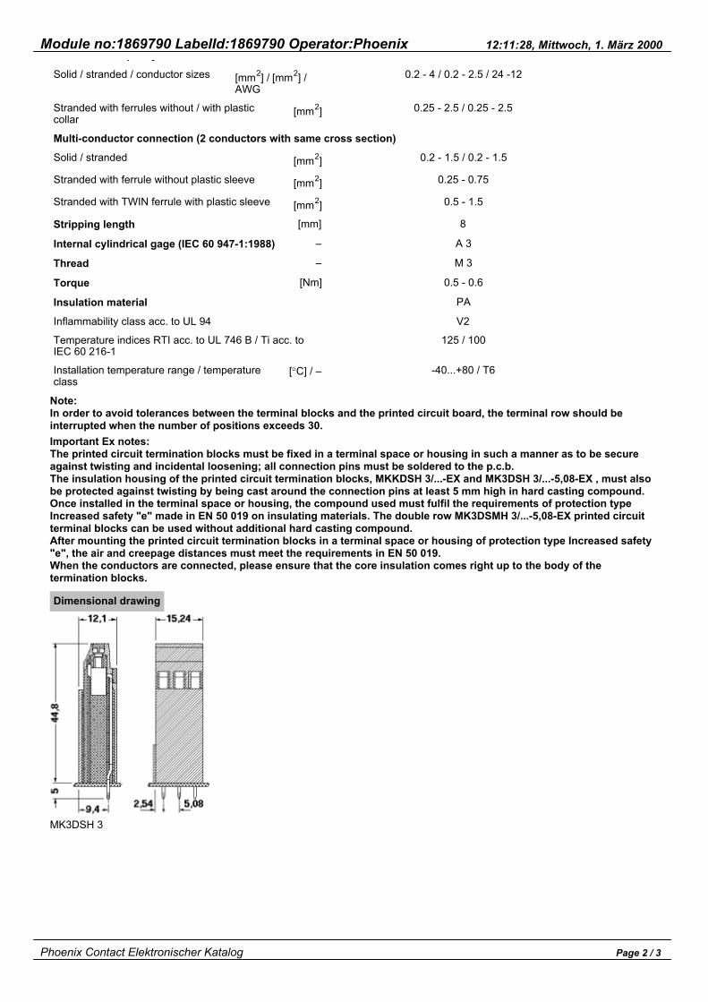
MKKDSH 3MK3DSH 3
High termination blocksPitch 5.0 or 5.08
(IEC)
[mm2]
Connection data
EN 50019 *
rigid
solid
0.2-4
0.2-4
flexible
stranded
0.2-2.5
0.2-2.5
AWG
24-12
–
I
[A]
24
27/20
U
[V]
250
66
* Certificate no.: BVS 97.D.7001UDMT-BVS
Description
Printed circuit screw termination blocks,5.0 mm pitch, with housing interlocking,color: green
Printed circuit screw termination blocks,5.08 mm pitch, with housing interlocking,color: green
No. ofpositions
2
3
2
3
Type
MKKDSH 3/2-EX
MKKDSH 3/3-EX
MK3DSH 3/2-5,08-EX
MK3DSH 3/3-5,08-EX
Order No.
18 69 79 0
18 69 80 0
18 69 77 4
18 69 78 7
Pcs. Pkt.
50
50
50
50
Accessories
(1) Single cover, to cover theindividual terminal positions, snapfitting, color: orange, transparent
(2) Screwdriver,blade: 0.6 x 3.5 x 100 mm,length: 180 mm
(3) Marker card, with 12 pcs.,10-section marker strips, white,self-adhesive, for 120 terminal blocks
EA-MKDS
SZS 0,6 x 3,5
SK 5/3,8…or SK 5,08/3,8…(see info)
17 11 40 8
12 05 05 3
1
10
Technical data
Dimensions
Pitch
Hole diameter
Pin dimensions
Technical data in accordance with IEC 60 999/ DIN VDE 0110
Insulation material group
Surge voltage category / contamination class
Rated voltage
Rated surge voltage
Nominal current / cross section
Maximum load current / crosssection
Connection capacity
[A] / [mm2]
[A] / [mm2]
[mm]
[mm]
[mm]
–
– / –
[V]
[kV]
see description
5.0 / 5.08
1.3
0.9 x 0.9
I
III / 3
250
4
24 / 2.5
24 / 4
III / 2
320
4
II / 2
630
4
Phoenix Contact Elektronischer Katalog Page 1 / 3
Module no:1869790 LabelId:1869790 Operator:Phoenix 12:11:28, Mittwoch, 1. März 2000p y
Solid / stranded / conductor sizes
Stranded with ferrules without / with plasticcollar
Multi-conductor connection (2 conductors with same cross section)
Solid / stranded
Stranded with ferrule without plastic sleeve
Stranded with TWIN ferrule with plastic sleeve
Stripping length
Internal cylindrical gage (IEC 60 947-1:1988)
Thread
Torque
Insulation material
Inflammability class acc. to UL 94
Temperature indices RTI acc. to UL 746 B / Ti acc. toIEC 60 216-1
Installation temperature range / temperatureclass
[mm2] / [mm2] /AWG
[mm2]
[mm2]
[mm2]
[mm2]
[mm]
–
–
[Nm]
[°C] / –
0.2 - 4 / 0.2 - 2.5 / 24 -12
0.25 - 2.5 / 0.25 - 2.5
0.2 - 1.5 / 0.2 - 1.5
0.25 - 0.75
0.5 - 1.5
8
A 3
M 3
0.5 - 0.6
PA
V2
125 / 100
-40...+80 / T6
Note:In order to avoid tolerances between the terminal blocks and the printed circuit board, the terminal row should beinterrupted when the number of positions exceeds 30.Important Ex notes:The printed circuit termination blocks must be fixed in a terminal space or housing in such a manner as to be secureagainst twisting and incidental loosening; all connection pins must be soldered to the p.c.b.The insulation housing of the printed circuit termination blocks, MKKDSH 3/...-EX and MK3DSH 3/...-5,08-EX , must alsobe protected against twisting by being cast around the connection pins at least 5 mm high in hard casting compound.Once installed in the terminal space or housing, the compound used must fulfil the requirements of protection typeIncreased safety "e" made in EN 50 019 on insulating materials. The double row MK3DSMH 3/...-5,08-EX printed circuitterminal blocks can be used without additional hard casting compound.After mounting the printed circuit termination blocks in a terminal space or housing of protection type Increased safety"e", the air and creepage distances must meet the requirements in EN 50 019.When the conductors are connected, please ensure that the core insulation comes right up to the body of thetermination blocks.
Dimensional drawing
MK3DSH 3
Phoenix Contact Elektronischer Katalog Page 2 / 3

Module no:1869790 LabelId:1869790 Operator:Phoenix 12:11:28, Mittwoch, 1. März 2000
Drilling diagram
MKKDSH 3
MK3DSH 3
Phoenix Contact Elektronischer Katalog Page 3 / 3

Module no:3003046 LabelId:3003046 Operator:Phoenix 14:32:23, Mittwoch, 1. März 2000
TP...
Description
Partition plate,for mounting rails NS 32 toEN 50 035 and NS 35/7,5and NS 35/15 to EN 50 022,2.2 mm thick,Material: PA,Color: gray
Partition plate,for mounting rails NS 35/7,5to EN 50 022 andNS 15 to EN 50 045,2 mm thick,Material: PA,Color: gray
Partition plate,for terminal blocks for printedcircuits KDS and GKDS,2 mm thick,Material: PA,Color: green
Type
TP-UK
TPN-UK
TPNS-UK
TP-BK/MBK
TP-KDS/GKDS
Order No.
30 03 04 6
30 03 06 2
07 06 64 7
08 01 79 1
17 01 79 3
Pcs. Pkt.
10
10
50
10
10
Dimensional drawing
TP-UK
TPN-UK
TPNS-UK
Phoenix Contact Elektronischer Katalog Page 1 / 2

Module no:3003046 LabelId:3003046 Operator:Phoenix 14:32:23, Mittwoch, 1. März 2000
TP-BK/MBK
Phoenix Contact Elektronischer Katalog Page 2 / 2

Module no:1709203 LabelId:1709203 Operator:Phoenix 11:17:52, Mittwoch, 1. März 2000
GKDS-EX
with EEx e II approvalPitch 7.5
(IEC)
[mm2]
Connectiondata1)
rigid
solid
4
flexible
stranded
2.5
AWG
–
I
[A]
26/20
U
[V]
275 2)
1) PTB certificate no. Ex-93.C.3136 U2) Max. 420 V can be obtained when a pitch spacer GRZ 2,5-Ex is inserted.
Description
Terminal block
color
black
Type
GKDS-EX
Order No.
17 09 20 3
Pcs. Pkt.
50
Accessories
(1) Pitch spacer, increases the pitch by 2.5 mm,interlocks with terminal block in the same shape,
(2) Flange plate, placed on each groupof terminal blocks or every 10 terminal blocks,color: black
(3) Insertionbridge, fully insul.,2-pos.
(4) Separating plate, in acc. with EN50 020 § 5.4, 2.5 mm thick,KRILEN, green, for intrinsically safecircuits
(5) Test plug, consisting of metal partand colored insulating sleeve
(6) Reducing plug, for connecting a 4mm Ø test plug to a 2.3 mm Ø testplug socket, insulation: gray
(7) Screwdriver,blade: 0.6 x 3.5 x 100 mm,length: 180 mm
(8) Marker card, with 12 pcs.,10-section marker strips, white,self-adhesive, for 120 terminal blocks
GRZ 2,5-EX
GRZ 2,5V-EX
EB 2-BK 4-EX 3)
TP-KDS/GKDS-EX
MPS-… (see info)
RPS
SZS 0,6 x 3,5
GKDS marking materialtype ZB 7,5(see info)
Imax.: 20 A
17 24 62 8
17 06 11 2
08 03 18 4
17 01 37 9
02 01 64 7
12 05 05 3
100
100
100
10
10
10
Phoenix Contact Elektronischer Katalog Page 1 / 3

Module no:1709203 LabelId:1709203 Operator:Phoenix 11:17:52, Mittwoch, 1. März 2000
Technical data
Dimensions
Pitch
Hole diameter
Pin dimensions
Technical data in accordance with IEC / DIN VDE
Insulation material group
Surge voltage category / contamination class
Rated voltage
Rated surge voltage
Nominal current / cross section
Maximum load current / crosssection
Imax. insertion bridge/cross section(solid/stranded)
Max. power dissipation
Connection capacity
solid / stranded / conductor sizes
stranded with ferrules without / with plasticcollar
Multiple connection (2 conductors with same crosssection)
solid / stranded
stranded with ferrules withoutplastic collar
stranded with TWIN ferrules withplastic collar
Stripping length
Internal cylindrical gage (IEC 947-1:1988)
Thread
Torque
Insulation material
Inflammability class acc. to UL 94
Temperature indices RTI/Ti
Approval data (UL and CSA)
Nominal voltage / current /conductor sizes
[A]/[mm2]/[mm2]
[W]
[mm2]/[mm2]/AWG
UL: [V] / [A] / AWG
CSA: [V] / [A] / AWG
[mm]
[mm]
[mm]
–
–/–
[V]
[kV]
[A]/[mm2]
[A]/[mm2]
[mm2]
[mm2]
[mm2]
[mm2]
[mm]
–
–
[Nm]
see description
20 / 2.5
26 / 4
20 / 2.5 / 1.5
0.2 - 4 / 0.2 - 2.5 / 24 - 12
0.25 - 2.5 / 0.25 - 2.5
0.2 - 1.5 / 0.2 - 1
0.25 - 0.5
0.5 - 1
125 / 110
––
––
7.5
1.4
1.1 x 0.8
––
––
275
––
––
9
A 3
M 3
0.5 - 0.6
PA
V2
3) Reduces connection cross section to 2.5 mm2 solid or 1.5 mm2 stranded.Articles printed in bold can be delivered at short notice.Products with black or gray housing available on request.
Dimensional drawing
Phoenix Contact Elektronischer Katalog Page 2 / 3

Module no:1709203 LabelId:1709203 Operator:Phoenix 11:17:52, Mittwoch, 1. März 2000
Drilling diagram
Phoenix Contact Elektronischer Katalog Page 3 / 3

Module no:1701159 LabelId:1701159 Operator:Phoenix 11:15:19, Mittwoch, 1. März 2000
FRONT 2,5-H/…
Pitch 5End cover width 2.5
(IEC)
[mm2]
Connection data
EN 50019 *
rigid
solid
0.2-2.5
2.5
flexible
stranded
0.2-2.5
2.5
AWG
24-14
–
I
[A]
24
20
U
[V]
250 1)
66 2)
* Certificate no.: L.C.I.E. Nr. 91.C0018 U
H L.C.I.E
Description
Terminal block, 5 mmpitch, connection directionhorizontal to the p.c.b.
End cover, necessary at theend of a terminal row, 2.5mm thick
Color
green
green
Pin spacing
[mm]
5
10
Type
FRONT 2,5-H/SA 5-EX
FRONT 2,5-H/SA 10-EX
D-FRONT 2,5-H
Order No.
17 01 15 9
17 00 32 5
17 00 02 4
Pcs. Pkt.
50
50
50
Accessories
(1) Pitch spacer, increases the pitchby 2.5 mm, interlocks with terminalblock in the same shape, color: green
(2) Screwdriver blade: 0.6 x 3.5 x 100mm, length: 180 mm
RZ 2,5-FRONT 2,5 H-EX
SZS 0,6 x 3,5
17 01 26 9
12 05 05 3
50
10
Technical data
Dimensions
Pitch
Hole diameter
Pin dimensions
Nominal data in acc. with IEC 60 999/ DIN VDE 0110
Insulation material group
Surge voltage category / contamination class
Rated voltage
Rated surge voltage
[mm]
[mm]
[mm]
–
–/–
[V]
[kV]
see description drawing
III / 3
250
4
5
1.2
0.8 x 0.8
I
III / 2
320
4
II / 2
630
4
Phoenix Contact Elektronischer Katalog Page 1 / 3

Module no:1701159 LabelId:1701159 Operator:Phoenix 11:15:19, Mittwoch, 1. März 2000Rated surge voltage
Nominal current / cross section
Maximum load current / crosssection
Connection capacity
Solid / stranded / conductor sizes
Stranded with ferrule without / with plastic sleeve
Multi-conductor connection (2 conductors with samecross section)
Solid / stranded
Stranded with ferrule without plastic sleeve
Stripping length
Internal cylindrical gage (IEC 60 947-1:1988)
Thread
Torque
Insulation material
Inflammability class acc. to UL 94
Temp. indices RTI acc. to UL 746 B / Ti acc. to IEC 60216-1
Installation temperature range / temperatureclass
[A] / [mm2]
[mm2] / [mm2] /AWG
[kV]
[V]
[mm2]
[mm2]
[mm2]
[mm]
–
–
[Nm]
[°C] / –
4
0.2 - 2.5 / 0.2 - 2.5 / 24 - 14
0.25 - 1.5 / 0.25 - 1.5
0.2 - 0.75 / 0.2-0.75
0.25 - 0.34
9
A 3
M 2.5
0.4 -0.5
PA
V2
125 / 100
-25...+80 / T6
4
24 / 2.5
24 / 2.5
4
1)2)
With one inserted pitch spacer RZ 2,5-FRONT 2,5..., 400 V are reached
275 V with one inserted pitch spacer,
418 V with two inserted pitch spacers.
Important Ex note:Mounting the terminal blocks on the p.c.b. may not result in any changes in the characteristic values (creepage and airdistances). The mechanical stability of the solder connection on the p.c.b. is also created by, e.g. bending the solderpins of the terminal blocks aligned to form one block.
Dimensional drawing
FRONT 2,5-H/SA 5 (-EX)
Drilling diagram
FRONT 2,5-H/SA 10 (-EX)
Phoenix Contact Elektronischer Katalog Page 2 / 3

Module no:1701159 LabelId:1701159 Operator:Phoenix 11:15:19, Mittwoch, 1. März 2000
FRONT 2,5-H/SA 5 (-EX)
Phoenix Contact Elektronischer Katalog Page 3 / 3

Module no:1701162 LabelId:1701162 Operator:Phoenix 11:15:25, Mittwoch, 1. März 2000
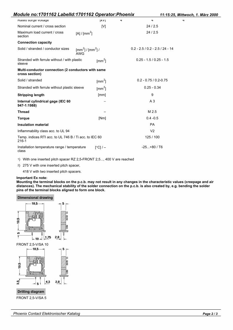
FRONT 2,5-V/…
Pitch 5End cover width 2.5
(IEC)
[mm2]
Connection data
EN 50019 *
rigid
solid
0.2-2.5
2.5
flexible
stranded
0.2-2.5
2.5
AWG
24-14
–
I
[A]
24
20
U
[V]
250 1)
66 2)
* Certificate no.: L.C.I.E. Nr. 91.C0018 U
H L.C.I.E
Description
Terminal block, 5 mmpitch, connection directionvertical to the p.c.b.
End cover, necessary at theend of a terminal row, 2.5mm thick
Color
green
green
Pin spacing
[mm]
5
10
Type
FRONT 2,5-V/SA 5-EX
FRONT 2,5-V/SA 10-EX
D-FRONT 2,5-V
Order No.
17 01 16 2
17 00 30 9
17 00 01 1
Pcs. Pkt.
50
50
50
Accessories
(1) Pitch spacer, increases the pitchby 2.5 mm, interlocks with terminalblock in the same shape, color: green
(2) Screwdriver blade: 0.6 x 3.5 x 100mm, length: 180 mm
RZ 2,5-FRONT 2,5 V-EX
SZS 0,6 x 3,5
17 00 79 4
12 05 05 3
50
10
Technical data
Dimensions
Pitch
Hole diameter
Pin dimensions
Nominal data in acc. with IEC 60 999/ DIN VDE 0110
Insulation material group
Surge voltage category / contamination class
Rated voltage
Rated surge voltage
[mm]
[mm]
[mm]
–
–/–
[V]
[kV]
see description drawing
III / 3
250
4
5
1.2
0.8 x 0.8
I
III / 2
320
4
II / 2
630
4
Phoenix Contact Elektronischer Katalog Page 1 / 3
Module no:1701162 LabelId:1701162 Operator:Phoenix 11:15:25, Mittwoch, 1. März 2000Rated surge voltage
Nominal current / cross section
Maximum load current / crosssection
Connection capacity
Solid / stranded / conductor sizes
Stranded with ferrule without / with plasticsleeve
Multi-conductor connection (2 conductors with samecross section)
Solid / stranded
Stranded with ferrule without plastic sleeve
Stripping length
Internal cylindrical gage (IEC 60947-1:1988)
Thread
Torque
Insulation material
Inflammability class acc. to UL 94
Temp. indices RTI acc. to UL 746 B / Ti acc. to IEC 60216-1
Installation temperature range / temperatureclass
[A] / [mm2]
[mm2] / [mm2] /AWG
[kV]
[V]
[mm2]
[mm2]
[mm2]
[mm]
–
–
[Nm]
[°C] / –
4
0.2 - 2.5 / 0.2 - 2.5 / 24 - 14
0.25 - 1.5 / 0.25 - 1.5
0.2 - 0.75 / 0.2-0.75
0.25 - 0.34
9
A 3
M 2.5
0.4 -0.5
PA
V2
125 / 100
-25...+80 / T6
4
24 / 2.5
24 / 2.5
4
1)2)
With one inserted pitch spacer RZ 2,5-FRONT 2,5..., 400 V are reached
275 V with one inserted pitch spacer,
418 V with two inserted pitch spacers.
Important Ex note:Mounting the terminal blocks on the p.c.b. may not result in any changes in the characteristic values (creepage and airdistances). The mechanical stability of the solder connection on the p.c.b. is also created by, e.g. bending the solderpins of the terminal blocks aligned to form one block.
Dimensional drawing
FRONT 2,5-V/SA 10
Drilling diagram
FRONT 2,5-V/SA 5
Phoenix Contact Elektronischer Katalog Page 2 / 3

Module no:1701162 LabelId:1701162 Operator:Phoenix 11:15:25, Mittwoch, 1. März 2000
FRONT 2,5-V/SA 10
Phoenix Contact Elektronischer Katalog Page 3 / 3

Module no:2780014 LabelId:2780014 Operator:Phoenix 13:23:52, Mittwoch, 1. März 2000
UXKK 4
Terminal width 6.2
(IEC)
[mm2]
IEC 60 947-7-1
EN 50 019 *
rigid
solid
0.2-4
0.2-4
flexible
stranded
0.2-4
0.2-4
AWG
24-12
–
I
[A]
32
21
U
[V]
800
726
* Certificate no.: KEMA Ex-95.D.8889U
HE KEMA/KDB
Description
Terminal block, with universal foot for mounting on 4or 3
Type
UXKK 4
Order No.
27 80 01 4
Pcs. Pkt.
50
Accessories
(1) End cover
(2) Fixed bridge, for crossconnections in the terminal center,10-position, divisible, with 10 screws
(7) Zack strip,10-section, white
enclosed housing
no end cover
FB 10-6-EX
ZB 8 (see info)
Imax.: 27 A 02 01 28 1 10
Technical data
Dimensions
Width / length
Height (NS 35:7.5 / NS 35:15 / NS 32)
Technical data in accordance with IEC 60 947-7-1/IEC60 947-7-2
Maximum load current / cross section
Rated surge voltage / contamination class
Surge voltage category / insulation materialgroup
Connection capacity
Stranded with ferrule with / without plasticsleeve
Continuity (two conductors with same cross section)
Solid / stranded
Stranded with ferrule without plastic sleeve
[mm]
[mm]
[A] / [mm2]
[kV] / –
– / –
[mm2]
[mm2]
[ 2]
6.2 / 84.5
64 / 71.5 / 68.5
32 / 4
8 / 3
III / I
0.25 - 4 / 0.25 - 1.5
0.2 - 2.5 / 0.2 - 2.5
0 25 - 2 5
Phoenix Contact Elektronischer Katalog Page 1 / 2

Module no:2780014 LabelId:2780014 Operator:Phoenix 13:23:52, Mittwoch, 1. März 2000Stranded with ferrule without plastic sleeve
Stranded with TWIN ferrule with plasticsleeve
Stripping length
Internal cylindrical gage (IEC 60947-1:1988)
Screw thread
Torque
Insulation material
Inflammability class acc. to UL 94
Temp. indices RTI acc. to UL 746 B / Ti acc. to IEC 60216-1
Installation temperature range / temperatureclass
[mm2]
[mm2]
[mm]
[Nm]
[°C] / –
0.25 - 2.5
0.5 - 1.5
8
A 3
M 3
0.6 - 0.8
PA
V2
125 / 100
-40...+80 / T6
Important notes:All clamping screws must be tightened.If these elements are mixed with other series and sizes and if other accessories are used, the required air and creepagedistances must be complied with.Important note:The notched partition plate must first be removed to bridge the terminal blocks.
Phoenix Contact Elektronischer Katalog Page 2 / 2

Module no:0531207 LabelId:0531207 Operator:Phoenix 09:30:58, Mittwoch, 1. März 2000
UK 4-EX
Terminal width 6.2
(IEC)
[mm2]
IEC 60 947-7-1
EN 50 019 *
rigid
solid
0.2-4
0.5-4
flexible
stranded
0.2-4
0.5-2.5
AWG
24-12
–
I
[A]
32
30/23
U
[V]
1000
7261)
* Certificate no.: KEMA Ex-95.D.8574U
H KEMA/KDB
Description
Terminal block, with universal foot for mounting on 4or 3
Type
UK 4-EX
Order No.
05 31 20 7
Pcs. Pkt.
50
Accessories
(1) Fixed bridge, forcross connections in theterminal center, divisible,with screws
(2) Chain bridge, for cross bridging interminal center across any no. ofterminal blocks, 1-pos. with screw
(3) Insertion bridge, fully insulated,2-pos.
fully insulated, 3-pos.
insulated spine, divisible, 10-pos.
(4) Cross connection bar, for fixedbranches at any point (with ZS-6 orZSR-EX), in Cu, nickel-plated, 1 mlong
(5) Distance piece in metal, forbranches from FB-150, with screw andpressure plate
(6) Partition plate, for visual andelectrical separation of terminalgroups, 1.5 mm thick
(7) Zack strip,10-section, white
10-pos. FB 10-6
KB-6
EB 2-6
EB 3-6
EB 10-6
FB-150
ZS-6
ATP-UK 5-MTK
ZB 6 (see info)
Imax.: 29 A
Imax.: 29 A
Imax.: 25 A
25 A
25 A
Imax.: 27 A
02 01 18 4
02 01 47 2
02 01 15 5
02 01 14 2
02 01 13 9
02 01 59 5
02 01 60 5
30 04 21 0
10
100
100
100
10
1
100
50
Phoenix Contact Elektronischer Katalog Page 1 / 2

Module no:0531207 LabelId:0531207 Operator:Phoenix 09:30:58, Mittwoch, 1. März 2000
Technical data
Dimensions
Width / length
Height (NS 35:7.5 / NS 35:15 / NS 32)
Technical data in accordance with IEC 60947-7-1
Maximum load current / cross section
Max. cross section with insertion bridge (solid/ stranded)
Rated surge voltage / contamination class
Surge voltage category / insulation materialgroup
Connection capacity
Stranded with ferrule with / without plasticsleeve
Multi-conductor connection (2 conductors with samecross section)
Solid / stranded
Stranded with ferrule without plastic sleeve
Stranded with TWIN ferrule with plastic sleeve
Stripping length
Internal cylindrical gage (IEC 60947-1:1988)
Thread
Torque
Insulation material
Inflammability class acc. to UL 94
Temp. indices RTI acc. to UL 746 B / Ti acc. to IEC 60216-1
Installation temperature range / temperatureclass
[mm]
[mm]
[A] / [mm2]
[mm2]
[kV] / –
– / –
[mm2]
[mm2]
[mm2]
[mm2]
[mm]
[Nm]
[°C] / –
6.2 / 42.5
47 / 54.5 / 52
32 / 4
4 / 2.5
8 / 3
III / I
0.25 - 4 / 0.25 - 4
0.2 - 1.5 / 0.2 - 1.5
0.25 - 1.5
0.5 - 1.5
9
A 3
M 3
0.6 - 0.8
PA
V2
125 / 100
-40...+80 / T6
1) The max. nominal voltage is determined by the mounting rails, at 4 418 V.Important Ex note:If the fixed bridges and chain bridges are used, a partition plate is necessary between bridges which make directcontact, and a cover is required at the beginning and end of each bridge.Accordingly, equipotential bondings that were created with insertion bridges must be separated by means of partitionplates.If the fixed bridges FB 150 are used for bridging of non-adjacent terminals, the max. nominal voltage is reduced to 275V.If these elements are mixed with other series and sizes and if other accessories are used, the required air and creepagedistances must be complied with.
Phoenix Contact Elektronischer Katalog Page 2 / 2

Module no:0531210 LabelId:0531210 Operator:Phoenix 09:31:04, Mittwoch, 1. März 2000
UK 4-EX BKYE-FE
Terminal width 6.2
(IEC)
[mm2]
IEC 60 947-7-1
EN 50 019 *
rigid
solid
0.2-4
0.5-4
flexible
stranded
0.2-4
0.5-2.5
AWG
24-12
–
I
[A]
32
30/23
U
[V]
1000
7261)
* Certificate no.: KEMA Ex-95.D.8574UKEMA
Description
Terminal block, with universal foot for mounting on 4or 3
Type
UK 4-EX BKYE
Order No.
05 31 21 0
Pcs. Pkt.
50
Accessories
(1) Fixed bridge, forcross connections in theterminal center, divisible,with screws
(2) Chain bridge, for cross bridging interminal center across any no. ofterminal blocks, 1-pos. with screw
(3) Insertion bridge, fully insulated,2-pos.
fully insulated, 3-pos.
insulated spine, divisible, 10-pos.
(4) Cross connection bar, for fixedbranches at any point (with ZS-6 orZSR-EX), in Cu, nickel-plated, 1 mlong
(5) Distance piece in metal, forbranches from FB-150, with screw andpressure plate
(6) Partition plate, for visual andelectrical separation of terminalgroups, 1.5 mm thick
(7)Zack strip,10-section, white
10-pos. FB 10-6
KB-6
EB 2-6
EB 3-6
EB 10-6
FB-150
ZS-6
ATP-UK 5-MTK
ZB 6 (see info)
Imax.: 29 A
Imax.: 29 A
Imax.: 25 A
25 A
25 A
Imax.: 27 A
02 01 18 4
02 01 47 2
02 01 15 5
02 01 14 2
02 01 13 9
02 01 59 5
02 01 60 5
30 04 21 0
10
100
100
100
10
1
100
50
Phoenix Contact Elektronischer Katalog Page 1 / 2

Module no:0531210 LabelId:0531210 Operator:Phoenix 09:31:04, Mittwoch, 1. März 2000
Technical data
Dimensions
Width / length
Height (NS 35:7.5 / NS 35:15 / NS 32)
Technical data in accordance with IEC 60947-7-1
Maximum load current / cross section
Max. cross section with insertion bridge (solid/ stranded)
Rated surge voltage / contamination class
Surge voltage category / insulation materialgroup
Connection capacity
Stranded with ferrule with / without plasticsleeve
Multi-conductor connection (2 conductors with samecross section)
Solid / stranded
Stranded with ferrule without plastic sleeve
Stranded with TWIN ferrule with plastic sleeve
Stripping length
Internal cylindrical gage (IEC 60947-1:1988)
Thread
Torque
Insulation material
Inflammability class acc. to UL 94
Temp. indices RTI acc. to UL 746 B / Ti acc. to IEC 60216-1
Installation temperature range / temperatureclass
[mm]
[mm]
[A] / [mm2]
[mm2]
[kV] / –
– / –
[mm2]
[mm2]
[mm2]
[mm2]
[mm]
[Nm]
[°C] / –
6.2 / 42.5
47 / 54.5 / 52
32 / 4
4 / 2.5
8 / 3
III / I
0.25 - 4 / 0.25 - 4
0.2 - 1.5 / 0.2 - 1.5
0.25 - 1.5
0.5 - 1.5
9
A 3
M 3
0.6 - 0.8
PA
V2
125 / 100
-40...+80 / T6
1) The max. nominal voltage is determined by the mounting rails, at 4 418 V.Important Ex note:If the fixed bridges and chain bridges are used, a partition plate is necessary between bridges which make directcontact, and a cover is required at the beginning and end of each bridge.Accordingly, equipotential bondings that were created with insertion bridges must be separated by means of partitionplates.If the fixed bridges FB 150 are used for bridging of non-adjacent terminals, the max. nominal voltage is reduced to 275V.If these elements are mixed with other series and sizes and if other accessories are used, the required air and creepagedistances must be complied with.
Phoenix Contact Elektronischer Katalog Page 2 / 2