akmal waheed – challenge 2 design solution
DESCRIPTION
The first Technology driven reality competition showcasing the incredible virtualization community members and their talents.TRANSCRIPT

Prepared By:
Akmal Waheed
@akmal_waheed
Challenge -2
Virtual Design
Master
Challenge 2: Zombies rise!
Zombies rise!!! Page 1

Purpose and Overview1.
1.1 Executive Summary1.2 Case Background1.3 Interpreting This Document1.4 Requirement | Constraints | Assumptions1.5 Current Environment1.6 Conceptual Architecture Overview Diagram
Disaster Recovery and Business Continuity Solution2.
2.1 Site Recovery Manager 5.12.2 Disaster Recovery Topologies2.3 RPO | RTO | SLA2.4 NetApp Storage & SRM
Planned Migration Process3.
3.1 Planned Migration to Secondary Site3.2 Planned Migration to Tertiary Site
Disaster Recovery Plan4.
4.1 Bi-Directional Failover 4.2 Recovery Plans | Failover4.3 Virtual Desktop and Application Failover
Pricing Details5.
Conclusion6.
Table of Contents
Zombies rise!!! Page 2

This architecture is developed to address two major requirements,
To have a planned migration of 5000 Virtual Servers from one site to 2 sites which are already running certain number of Virt ual Servers.1.To provide a Disaster Recovery and reliable Disaster Protection solution for all the Virtual Servers, Virtual Desktops and th e Applications.2.
This design would also have automated Disaster Recovery plans for testing and planned migrations.
1.2 Case Background
The zombies have infiltrated our primary datacenter and soon they would destroy the Primary Site. Currently the Primary Site is completely functional and accessible via the network to move the resources. Compute, Network and Storage could be added to manage the migrations of Virtual Servers from Primary Site to other two Sites.
1.3 Interpreting This Document
The overall structure of this document is self-explanatory. It consists of many conceptual, Logical and physical diagrams to provide details of the proposed solution. Wherever any specific solution or hardware is used, it is supported by design consideratio ns. In some cases, customer-specific requirements and existing infrastructure constraints might result in a valid but suboptimal design choice.
1.1 Executive Summary
Zombies rise!!! Page 3

In this project the main requirement is to move the 5000 Virtual Servers from Primary Datacenter to Secondary and Tertiary Site, while still maintaining 1000 Virtual Server and 500 Virtual Servers in Secondary and Tertiary Site respectively. Additional compute and storage at Secondary and Tertiary site would added depending on the number of Virtual Servers moved from Primary site and the calculations for the same is provided in the respective sections.
After all the 5000 Virtual Servers are distributed among Secondary and Tertiary Site, a robust Disaster Recovery workflow and Disaster Avoidance design would be implemented so that the environment would be ready for any unpredictable Service unavailability, which could come from natural disasters like Hurricane, fire, complete power outage etc.
Throughout this design document, we will adhere to the standards and best practices as defined by Vmware. Would meet all the functional requirement and adhere to the constraints.
Functional Requirement - Mandatory condition that must be satisfied. List includes Technological, business and operational requirements
ID Requirement
r1 Secondary and Tertiary sites will have to maintain the entire load of the formerly 3 datacenters
r2 Disaster Recovery and Business Continuity plan
r3 RPO and RTO for the different environments (Virtual Server, Virtual Desktop and Application)
r4 Virtual Desktop and Virtual Application failover process description
r5 Move 5000 Virtual Servers from Primary site to the other two sites
r6 Secondary Site still hosts its 1000 Virtual Servers
r7 Tertiary Site still hosts its 500 Virtual Servers
r8 3000 Virtual Desktops with full desktop access.
r9 Application Delivery for atleast 1500 devices.
r10 Central Repository to store and share documents and data.
r11 Pricing information for the protection of Environment with a breakdown of the Licensing
Constraints- Constraints limit the logical design decisions and physical specifications. List includes Technological and operational
constraints
ID Constraints
c1 All the hardware is 5 years old, i.e., April 2008.
c2 1 Gig speed Ethernet card only
c3 4 Gig speed Fibre Channel only.
c4 WAN connectivity has been provided between the sites (Point-to-point 100Mb)
c5 Internet connection available in both the Secondary and Tertiary site (100Mb each location)
Assumptions: Any aspect of the design that accepted as fact but not backed by a requirement or a constraint. This list of the
assumptions which are made to start the project, it doesn’t consists of all the assumptions, but every assumption is stated as and when it used for any design decisions.
ID Assumptions
a1 AD, DNS, NTP configured and in sync across all 3 Datacenters
a2 Point to point network connectivity between 3 sites.
a3 All Virtual Server have same load and sizing.
a4 All Virtual Desktops have same load and sizing.
a5 Physical Storage configuration and connectivity is done by Storage Admin.
a6 Physical Network configuration and connectivity is done by Network Admin.
1.4 Requirement | Constraints | Assumptions
Zombies rise!!! Page 4

In the first stage 3 Datacenter were built hosting 5000, 1000 and 500 Virtual Server in Primary, Secondary and Tertiary sites respectively. Also, solution for 3000 Virtual Desktops and Application delivery for 1500 device were deployed in Tertiary Datacenter. All the 3 Datacenters had adequate amount of resources to handle sudden spike or hardware failure as all the compute and storage resources were configured with atleast 20% headroom and 8-10% anticipated growth. This is how the complete environment's logical view looks like
SSO
vCenter Services
ManagementCluster
3 Hosts
Infra Cluster 1
2500Virtual Servers
27 Hosts
Infra Cluster 2
2500Virtual Servers
27 Hosts
SSO
vCenter Services
ManagementCluster
3 Hosts
Infra Cluster
1000Virtual Servers
11 Hosts
44 TB
NetApp FAS 3040
NetApp FAS 2050
193.8 TB
Primary Datacenter
1.5 Current Environment
Zombies rise!!! Page 6

SSO
vCenter Services
ManagementCluster
3 Hosts
Infra Cluster 1
500Virtual Servers
7 Hosts
3 - VDI Cluster
Total 45 Hosts
3000 Virtual Desktops
62.2 TB
44 TB
NetApp FAS 2050
NetApp FAS 2050
1500 App Delivery
Secondary Datacenter
Tertiary Datacenter
Zombies rise!!! Page 7

The primary requirement is to have a planned migration for 5000 Virtual Servers to 2 different sites. The Primary site has 3 clusters, Management, Infra-1 and Infra-2 cluster. All the 5000 Virtual Servers are part of the two Infra clusters, each with 2500 Virtual Servers.
Additional Compute considerations:
The current configuration has 27 ESXi hosts in each cluster with N+2 availability factor and 10% anticipated growth with 20% compute headroom. Now when we are planning for planned migration on the other sites, we could exclude the 10% growth calculation
Cluster Name Cluster Size HA Availability DRS DPM EVC
Management 3 Enabled N+1 Enabled Enabled Enabled
Infra-1 27 Enabled N+2 Enabled Enabled Enabled
Infra-2 27 Enabled N+2 Enabled Enabled Enabled
10% of 27 = 2.7
Total number of Servers required to host Approx. 2500 Virtual Servers at the other site if we are migrating the complete cluster (Infra-1 or Infra-2) to respective site, say Infra-1 to Secondary site and Infra-2 to Tertiary Site
27-2.7 = 24.3 = 25
Hence, at the other site the total number of hosts required to manage 2500 Virtual Servers is 25.
Additional Storage Considerations:
2550 Virtual Servers would be migrated to Secondary and 2450 Virtual Servers would be migrated to Tertiary Site. Each of the Virtual Server is allocated with 30 GB of storage.
Hence, storage required for 2550 Virtual Servers
2550 x 30 = 76500 GB
Including 15% headroom for swap files, Virtual Machine snapshots, log files etc
15% of 76500 GB = 11475 GB
Total required space76500 + 11475 = 87975 GB (Recommended)
Similarly for 2450 Virtual Servers, the required storage at Recovery Site would be (with 10% headroom)84525 (Recommended)
As per the above plan, after successful migration of 5000 Virtual Servers, the Secondary and Tertiary Site would look something like this
1.6 Conceptual Architecture Overview Diagram
Zombies rise!!! Page 8

SSO
vCenter Services
ManagementCluster
3 Hosts
Infra Cluster
1000Virtual Servers
11 Hosts
SSO
vCenter Services
ManagementCluster
3 Hosts
Infra Cluster 1
500Virtual Servers
7 Hosts
3 - VDI Cluster
Total 45 Hosts
3000 Virtual Desktops
62.2 TB
44 TB
NetApp FAS 2050
NetApp FAS 2050
1500 App Delivery
PrimaryInfra 1
2500Virtual Servers
25 Hosts
Primary Infra 2
2500Virtual Servers
25 Hosts
Secondary Datacenter
88 TB
NetApp FAS 2050
Tertiary Datacenter
85 TB
NetApp FAS 2050
Important: Additional vCenter Server at Tertiary Site to achieve Disaster Recovery plan for VMware View environment. More details in the respective section (4.3). The changes which mentioned in 4.3 would be performed before the Planned Migration phase.
Zombies rise!!! Page 9
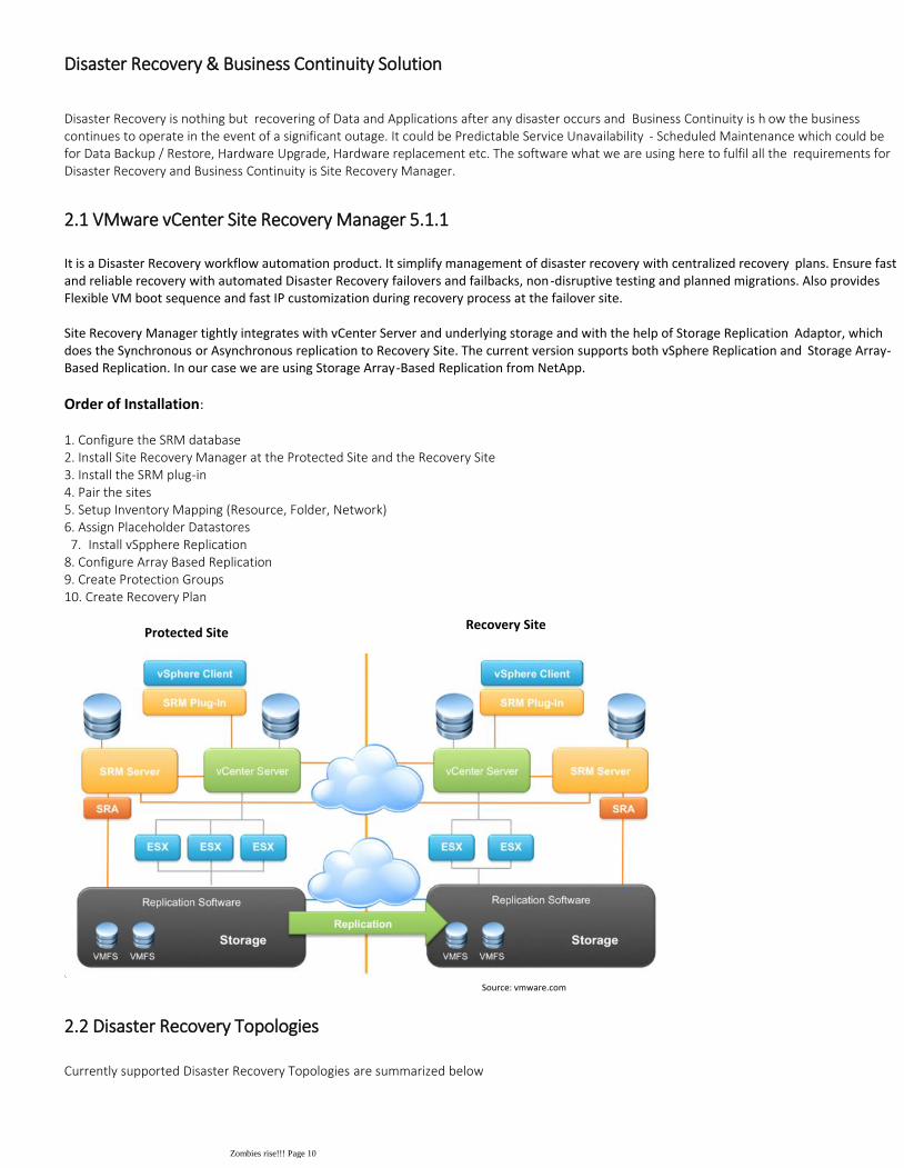
Disaster Recovery is nothing but recovering of Data and Applications after any disaster occurs and Business Continuity is h ow the business continues to operate in the event of a significant outage. It could be Predictable Service Unavailability - Scheduled Maintenance which could be for Data Backup / Restore, Hardware Upgrade, Hardware replacement etc. The software what we are using here to fulfil all the requirements for Disaster Recovery and Business Continuity is Site Recovery Manager.
2.1 VMware vCenter Site Recovery Manager 5.1.1
It is a Disaster Recovery workflow automation product. It simplify management of disaster recovery with centralized recovery plans. Ensure fast and reliable recovery with automated Disaster Recovery failovers and failbacks, non-disruptive testing and planned migrations. Also provides Flexible VM boot sequence and fast IP customization during recovery process at the failover site.
Site Recovery Manager tightly integrates with vCenter Server and underlying storage and with the help of Storage Replication Adaptor, which does the Synchronous or Asynchronous replication to Recovery Site. The current version supports both vSphere Replication and Storage Array-Based Replication. In our case we are using Storage Array-Based Replication from NetApp.
Order of Installation:
1. Configure the SRM database2. Install Site Recovery Manager at the Protected Site and the Recovery Site3. Install the SRM plug-in4. Pair the sites5. Setup Inventory Mapping (Resource, Folder, Network)
Install vSpphere Replication7.6. Assign Placeholder Datastores
8. Configure Array Based Replication9. Create Protection Groups10. Create Recovery Plan
Protected SiteRecovery Site
2.2 Disaster Recovery Topologies
Currently supported Disaster Recovery Topologies are summarized below
Source: vmware.com
Disaster Recovery & Business Continuity Solution
Zombies rise!!! Page 10

Source: vmware.com
In our case we would using two topologies in stages to fulfil the requirement of Planned Migrate and providing Disaster Recov ery Plan
Stage 1: Planned Migration of 5000 Virtual Servers
Active-Passive Failover between Primary Site and Secondary Site-
Active-Passive Failover between Primary Site and Tertiary Site-
More details in Section 3.
Stage 2: Disaster Recovery and Business Continuity
Bi-Directional Failover between Secondary and Tertiary Site.-
More details in Section 4.
Zombies rise!!! Page 11
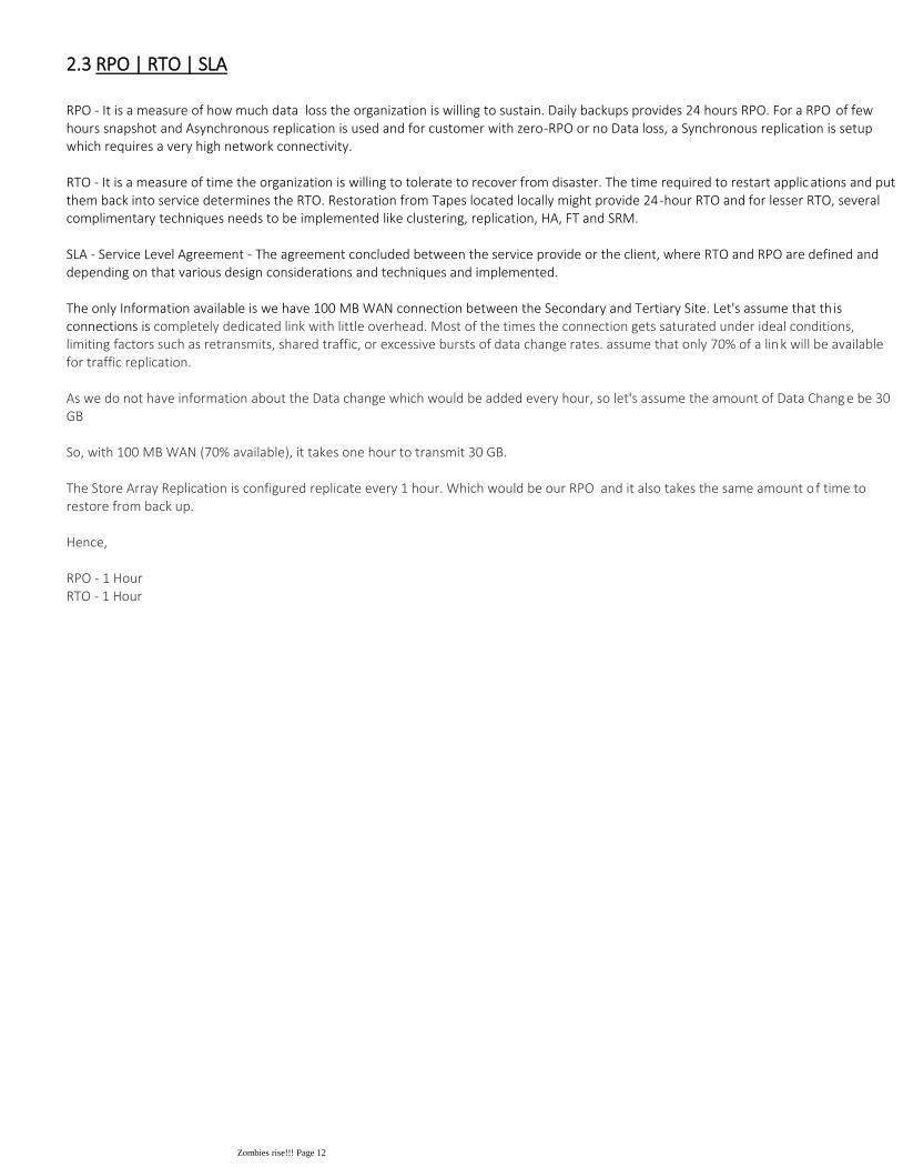
RPO - It is a measure of how much data loss the organization is willing to sustain. Daily backups provides 24 hours RPO. For a RPO of few hours snapshot and Asynchronous replication is used and for customer with zero-RPO or no Data loss, a Synchronous replication is setup which requires a very high network connectivity.
RTO - It is a measure of time the organization is willing to tolerate to recover from disaster. The time required to restart applic ations and put them back into service determines the RTO. Restoration from Tapes located locally might provide 24-hour RTO and for lesser RTO, several complimentary techniques needs to be implemented like clustering, replication, HA, FT and SRM.
SLA - Service Level Agreement - The agreement concluded between the service provide or the client, where RTO and RPO are defined and depending on that various design considerations and techniques and implemented.
The only Information available is we have 100 MB WAN connection between the Secondary and Tertiary Site. Let's assume that th is connections is completely dedicated link with little overhead. Most of the times the connection gets saturated under ideal conditions, limiting factors such as retransmits, shared traffic, or excessive bursts of data change rates. assume that only 70% of a link will be available for traffic replication.
As we do not have information about the Data change which would be added every hour, so let's assume the amount of Data Change be 30 GB
So, with 100 MB WAN (70% available), it takes one hour to transmit 30 GB.
The Store Array Replication is configured replicate every 1 hour. Which would be our RPO and it also takes the same amount of time to restore from back up.
Hence,
RPO - 1 Hour RTO - 1 Hour
2.3 RPO | RTO | SLA
Zombies rise!!! Page 12

We are using both Fibre Channel and NFS protocols from NetApp FAS3040 Array at Primary site and all the Virtual Servers are distributed on respective Datastore (FC or NFS) depending on the severity and SLAs. When we are planning for the Migration of these Virtual Machines to Secondary or Tertiary Sites, we need to make sure that these LUNs are replicated on newly added NetApp FAS2050 Array at the Secondary and Tertiary Site respectively. As per the plan we would migrate first Infra cluster of Primary Datacenter to Secondary Datacenter, which requires 25 ESXi hosts. These 25 Hosts will manage all the 2550 Virtual Servers after the successful Migration.
SnapMirror is the main data replication feature used with NetApp systems. It can perform synchronous, asynchronous, or semi-synchronous replication in either a Fibre Channel or IP network infrastructure. For SnapMirror to function it needs to be licensed and enabled on both systems. Below are the sequence of steps to configure Replication between Protected and Recovery Site (In our case between Primary and Secondary or Primary or Tertiary Site)
SnapMirror option needs to be enabled on both the Sites (Protected and Recovery). 1.Enable Remote Access (Both the Protected and Recovery Filers)2.A new mirror relationship is established with the Protected node from Recovery site.3.Once the volumes are authenticated, the administrator can browse them at the Protected Site and select the one to be mirrored.4.
Storage Replication Adaptor interrogates the array to discover which LUNs are being replicated, and enables the Recovery Site SRM to “mirror” your virtual machines to the recovery array.
2.4 NetApp Storage Replication Adaptor
Zombies rise!!! Page 13

In order to migrate 5000 Virtual Servers to Secondary and Tertiary Site respectively, we would have Infra-1 cluster moved to Secondary site and Infra-2 Cluster moved to Tertiary Site. We can achieve this by using Site Recovery Manager. It would be a two phase process
3.1 Planned Migration to Secondary Site
Phase 1: Primary and Secondary Site in Active-Passive Failover Topology
Install Site Recovery Manager on Primary Site, which would be the Primary Site1.It will tightly syncs with the vCenter Server at Primary Site and underlying NetApp FAS3040 Storage.2.Install Site Recovery Manager on Secondary Site, which would be the Recovery Site.3.Additional NetApp FAS2050 Array is added which would be used as destination for Array Based Replication.4.Once the mirror relationship is established, the replication of 2550 Virtual Servers from different Storage group (Gold, Silver and Bronze) is initiated.
5.
Below is the table summarizing the Datastore and the respective Virtual Machines which will be migrated to Secondary Site with the help of NetApp SnapMirror Replication. The LUNs respective to the Datastores mentioned in the below table are only replicated to the Secondary Site
6.
The above Datastore size and VMs per Datastore were calculated during Storage design consideration of Primary Site.
Resource Pool Datastore Name Datastore Size 15% Headroom Usable Datastore Size VMs per Datastore
Silver Infra01 15 TB 2.25 TB 12.75 TB 425
Silver Infra02 15 TB 2.25 TB 12.75 TB 425
Silver Infra03 15 TB 2.25 TB 12.75 TB 425
Gold Infra07 15 TB 2.25 TB 12.75 TB 425
Gold Infra08 15 TB 2.25 TB 12.75 TB 425
Bronze nfs01 15 TB 2.25 TB 12.75 TB 425
Total # of VMs 2550
The 2550 Virtual Servers from Primary Site would be migrated to Secondary Site. Below are the Resource and Datastore mapping for 2550 Virtual Servers.
Inventory Mapping
This involves mapping the resources (clusters and resource pools), folders, and networks of the Protected Site to the Recovery Site.
Resource Mapping:1.This is to make sure that after Planned Migration, the Virtual Machines are powered on to their respective Resource Pools as they were designated in the Primary Site.
Planned Migration
Planned Migration Process
Zombies rise!!! Page 14

Folder Mapping:2.
Primary Site Resource Secondary Site Resource
vc1.vdm.com vc2.vdm.com
Primary Datacenter
Infra-1 (Cluster) Primary Infra-1 (Cluster)
Management Resource Pool Management Resource Pool
Infra-1 Resource Pool Infra-1 Resource Pool
Infra-2 Resource Pool Infra-2 Resource Pool
Duplicating the Folder and Resource Pool structure at Secondary site (Recovery Site) offers more control and flexibility, especially during the failback process.
Primary Site Resource Secondary Site Resource
vc1.vdm.com vc2.vdm.com
High Priority High Priority
Medium Priority Medium Priority
Low Priority Low Priority
Network Mapping :3.
During test Recovery Plan the Recovery Site SRM will auto-matically put the replicated VMs into a bubble network which isolates them from the actual network using an internal vSwitch. This prevents possible IP and NetBIOS in Windows conflicts.
As we are performing Planned Migration, we would the real Network PortGroups mapped to the source. Site Recovery Manager has the option to automatically assign different IP / Subnet if there is a requirement.
Primary Site Resource Secondary Site Resource
vc1.vdm.com vc2.vdm.com
Primary Datacenter
dvSwitch0
Management VMs (40) dvPortgp Management VMs (40) dvPortgp
Zombies rise!!! Page 15

Infra-1 (50) dvportgp Infra-1 (50) dvportgp
Infra-2 (60) dvportgp Infra-2 (60) dvportgp
Placeholder Datastore : 4.
10 GB LUN at recovery site is created which is visible to all the Recovery Site ESXi hosts and is named as Primary_Placeholder_1. The Placeholder Datastore consists of the vmx and other required files, which are the reference to the Virtual Machines whichwould be part of Protection Group (created in the next step). Then these vmx files are pre-registered to the ESXi hosts (Recovery ). This also allocates the virtual machine to the default resource pool, network, and folder as set in the inventory mappings section.
Protection Group : 5.
A protection group is a collection of virtual machines and templates that you protect together by using SRM. One or more protection groups can be created in each recovery plan. A recovery plan specifies how SRM recovers the virtual machines in the protection groups that it contains. Protection groups consist of virtual machines that use the same datastore group. A datastore group consists of consistency groups. All of the virtual machines and templates in a consistency group replicate their filestogether, and all the virtual machines in the consistency group recover together
Protection Group Datastore Name
Silver 1 Infra01
Silver 2 Infra02
Silver 3 Infra03
Gold 1 Infra07
Gold 2 Infra08
Bronze 1 nfs01
Recovery Plan :6.
Our Protection Group includes 6 Datastores, which includes 2550 Virtual Servers. We will include every VM within the scope ofour Protection Groups (there is option to customize during the Planned Recovery). Recovery Plan created as mentioned below
Click the Recovery Plan from the Primary Site SRM console-
Select the Secondary Site (Where 2550 VMs will be recovered)-
Select all the 6 Protection Group or few Protection Group as per the nature of Virtual Machines-
Select the appropriate Network for Virtual Machines-
Name the plan as "Planned Migration to Secondary Site"-
Now,
Select the Recovery Plan created and customize if needed under Recovery Steps-
Select Recovery button and Accept the Recovery Confirmation-
Select planned Migration-
Zombies rise!!! Page 16

Select planned Migration-
-
Start the Planned Migration and wait till the success message comes up.-
After the successful Planned Migration, all the 2550 Virtual Servers would be part of Secondary Site and the Primary Site is left with Infra-2 Cluster with 2450 Virtual Servers.
Important: The SRM link between Primary and Secondary site is broken (unpaired) after confirming that all the Migrated 2550 Virtual Servers are up and running.
Zombies rise!!! Page 17

Phase 2: Primary and Tertiary Site in Active-Passive Failover Topology
Install the Site Recovery Manager on Tertiary Site, which would be the Recovery Site.1.Additional NetApp FAS2050 Array is added which would be used as destination for Array Based Replication.2.Once the mirror relationship is established, the replication of 2450 Virtual Servers from different Storage group (Gold, Silver and Bronze) is initiated.
3.
Below is the table summarizing the Datastores and the respective Virtual Machines which will be migrated to Tertiary Site with the help of NetApp SnapMirror Replication. The LUNs respective to the Datastores mentioned in the below table are only replicated to the Tertiary Site
4.
Important: Before we proceed with the Phase 2, Break the site pairing between Primary and Secondary (Active-Passive). To unpair or recreate the pairing of protected and recovery sites, both sites must be available. If you cannot restore the original protected site, you must reinstall SRM on the protected and recovery sites.
The above Datastore size and VMs per Datastore were calculated during Storage design consideration of Primary Site.
Planned Migration
The 2550 Virtual Servers from Primary Site would be migrated to Tertiary Site. The steps are exactly same as the previous stage just for the different Cluster- Infra-2. I would just highlight the changes supported with logical Diagram.
Protection Group:
Only the Protection Group would have different Datacenters and summarized below
Resource Pool Datastore Name Datastore Size 15% Headroom Usable Datastore Size VMs per Datastore
Silver Infra04 15 TB 2.25 TB 12.75 TB 425
Silver Infra05 15 TB 2.25 TB 12.75 TB 425
Silver Infra06 15 TB 2.25 TB 12.75 TB 425
Gold Infra09 15 TB 2.25 TB 12.75 TB 425
Gold Infra10 10.8 TB 1.62 TB 9.18 TB 306
Bronze nfs02 15 TB 2.25 TB 12.75 TB 425
Bronze VMs_ISO 5 TB 0.75 TB 4.25 TB 19
Total # of VMs 2450
Protection Group Datastore Name
Silver 4 Infra04
3.2 Planned Migration to Tertiary Site
Zombies rise!!! Page 18
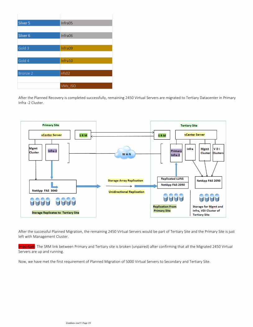
After the Planned Recovery is completed successfully, remaining 2450 Virtual Servers are migrated to Tertiary Datacenter in Primary Infra -2 Cluster.
After the successful Planned Migration, the remaining 2450 Virtual Servers would be part of Tertiary Site and the Primary Site is just left with Management Cluster.
Important: The SRM link between Primary and Tertiary site is broken (unpaired) after confirming that all the Migrated 2450 Virtual Servers are up and running.
Now, we have met the first requirement of Planned Migration of 5000 Virtual Servers to Secondary and Tertiary Site.
Silver 5 Infra05
Silver 6 Infra06
Gold 3 Infra09
Gold 4 Infra10
Bronze 2 nfs02
VMs_ISO
Zombies rise!!! Page 19

Now that we have all the 5000 Virtual Servers on Secondary and Tertiary Datacenter, it ideal for planning robust Disaster Recovery Plan for both the sites. As we are left with only two Datacenters and both are hosting large number of Virtual Servers, Virtual Desktops and Applications, then the only suitable Disaster Recovery protocol is "Bi-Directional Failover" Topology.
4.1 Bi-Directional Failover
At this stage we would pair the Site Recovery Manager between Secondary and Tertiary Site which is in Bi-Directional mode. With this topology both Sites are Protected Sites and at the same time Recovery Site for each other. We need to make sure in case of any unpredictable service unavailability or disaster the site should be capable of hosting all the Virtual Machines from the other in terms of both Compute and Storage in a fully automated way. Which means with just one button complete site should be migrated to the Recovery Site. To achieve this we would be adding more number of Servers (compute) and Storage depending on the Virtual Machine's nature running on the other Site.
Recovery Part of Secondary Site Recovery Part of Tertiary Site
Compute Requirement Storage Requirement Compute Requirement Storage Requirement
Infra Cluster (500 Virtual Machines) 15 TB Infra Cluster (1000 Virtual Machines) 30 TB
6 Hosts (excluding 10% growth) 17.25 TB (15 % Headroom) 10 Hosts (excluding 15% growth) 34.5 TB
Primary Infra-2 (2450 Virtual Machines) 73.5 TB Primary Infra-1 (2550 Virtual Machines) 76.5 TB
25 Hosts excluding 10% growth) 85 TB (15 % Headroom) 25 Hosts excluding 10% growth) 87.9 TB
VDI-1 Cluster (690 Virtual Desktops )
Below is the table summarizing the amount of storage and computing required for Recovery Plans with Secondary and Tertiary Site respectively. The Recovery section of Secondary Site consists of 5 clusters with total of 76 Hosts. To provide 102.25 TB (85 + 17.2 TB) of space we would add another Netapp FAS 3040 Storage Array configured to store the Replications of Tertiary Site's Protected Virtual Machines. Similarly, the Tertiary Site would have 2 Clusters with total of 35 Hosts and 122.4 TB space for Replicated Virtual Machines from the Secondary Site.
4. Disaster Recovery Plan
Zombies rise!!! Page 20

8 hosts
VDI-2 Cluster (690 Virtual Desktops )
8 hosts
VDI-3 Cluster (1620 Virtual Desktops )
29 Hosts (NFS Cluster)
These calculations were taken from the first challenge, and to recap
The number of ESXi hosts required per cluster at Recovery Site is after excluding the assumed 10% anticipated growth.1.All the Virtual Servers were assumed to have same load and size and are allocated with 30 GB drive each.2.
Below diagram shows the number of Protected and Recovery clusters and the number of Virtual Machines being Replicated.
Zombies rise!!! Page 21

Now that we have Bi-Directional Failover configured and Storage Array-Based Replication in place, we would proceed with creating the Protection Groups and Recovery Plans. In each SRM site, we would see both Protection Group and also the RecoveryPlan as single site is a Protected Site and Recovery Site for the paired Site. This Section includes Recovery Plans and Failover details only about Virtual Servers. Next section covers Virtual Desktops and Applications.
Secondary Site Protection Groups / Recovery Plan:
In case if the Tertiary Site goes down or for Planned Migration, all the Virtual Servers under "Recovery Plan Protection Group" will gracefully shutdown and restart on the Secondary host occupying the respective hosts in the Recovery Section with assign Inventory Mappings. Similarl configuration at the Tertiary Site but vice-versa.
Protection Group Datastore Name Recovery Plan Datastore Name
Protection Group
Silver 4 Infra04 Silver 1 Infra01
Protection Group Datastore Name Recovery Plan Datastore Name
Protection Group
Silver 1 Infra01 Silver 4 Infra04
Silver 2 Infra02 Silver 5 Infra05
Silver 3 Infra03 Silver 6 Infra06
Gold 1 Infra07 Gold 3 Infra09
Gold 2 Infra08 Gold 4 Infra10
Bronze 1 nfs01 Bronze 2 nfs02
VMs_ISO
This how the Site looks like after complete configuration with Protected and Recovery Section.
Secondary Site
4.2 Recovery Plans | Failover
Zombies rise!!! Page 22
Silver 5 Infra05 Silver 2 Infra02
Silver 6 Infra06 Silver 3 Infra03
Gold 3 Infra09 Gold 1 Infra07
Gold 4 Infra10 Gold 2 Infra08
Bronze 2 nfs02 Bronze 1 nfs01
VMs_ISO
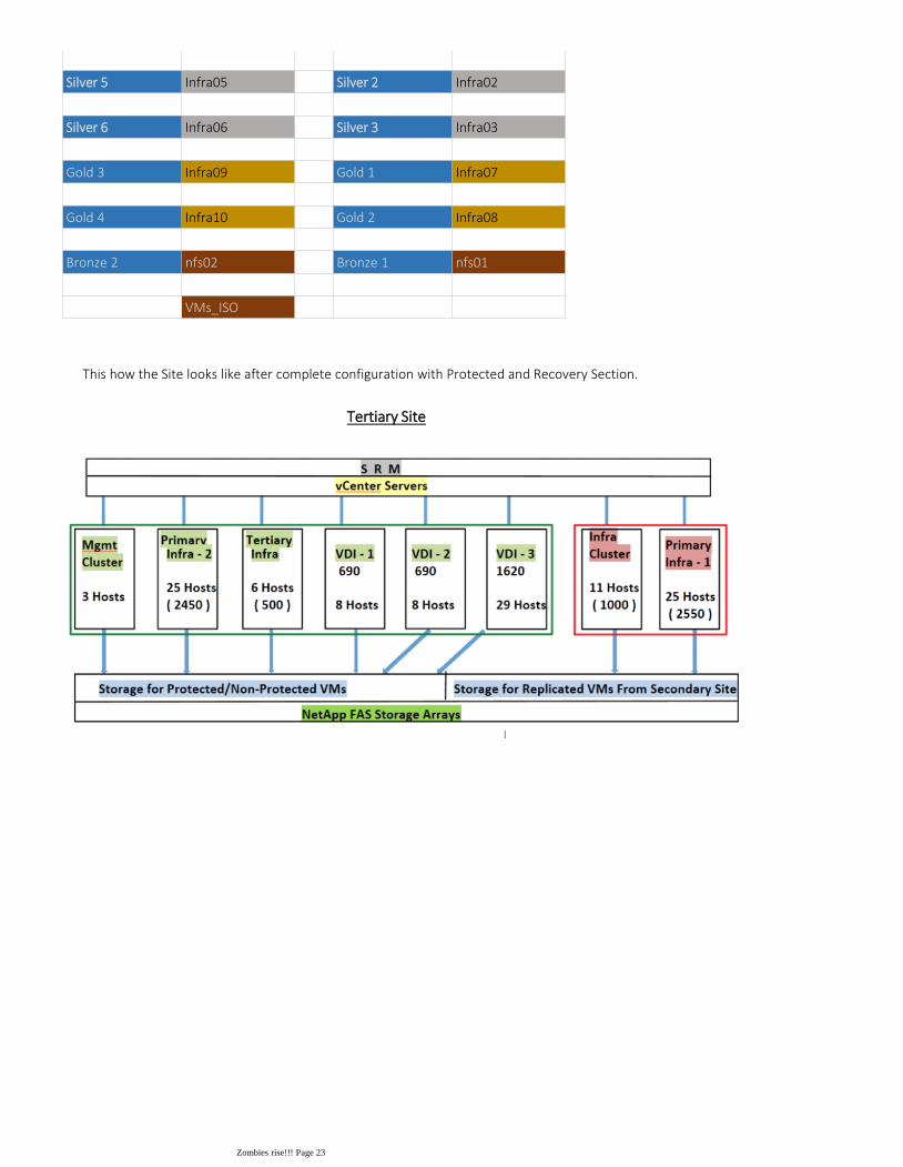
This how the Site looks like after complete configuration with Protected and Recovery Section.
Tertiary Site
Zombies rise!!! Page 23

VMware vCenter Site Recovery Manager 5.1 and earlier versions do not include native support for the protection of VMware View. It is important to have dedicated vCenter Server for View Environment and Workspace to implement the protection using vCenter Site Recovery Manager. Currently there is one vCenter Server which is managing both Virtual Servers and Virtual Desktops, i.e., Vmware Horizon View 5.2 and Vmware Horizon Workspace.
Now to provide Recovery Plan and failover for Vmware View and Worksapce we need have dedicated vCenter Server instance. So, instead of creating new vCenter Server for Vmware Horizon View 5.2, we would continue using the existing vCenter Server of Tertiary Site and we will make sure it is only dedicated to Vmware Horizon View and Horizon Workspace. Rest of the environment would be managed by the new Virtual Center. Now there are few major changes which needs to be done before installing the Site Recovery Manager in Tertiary Site, which are
Unlink the existing vCenter from linked mode. Follow the below simple steps to unlink without any impact.1.kb.vmware.com/kb/1010432
Install new vCenter Server pointing to SSO in multisite and then connect this instance in linked mode with Secondary Site's vCenter Server.2.
Once the new vCenter Server is installed, manually create same Datacenter name, cluster name and resource pools etc. Disable HA, DRS and DPM on the clusters of old Datcenter.
3.
The Existing vCenter consists of one Management Cluster (3 Hosts) and one Infra cluster (before planned migration stage). Disconnect the 3 ESXi hosts from Management Cluster of old vCenter Server and add it to the new vCenter Server.
4.
Now disconnect ESXi hosts and add them to new vCenter Server one by one while the Virtual Machines are still running. 5.
4.4 Virtual Desktop and Application Failover
After the fifth step, we have completed this task which results in 2 vCenter Servers, one for management and other for Horizon View and Horizon Workspace. The management vCenter Server runs as a virtual machine in the vSphere cluster it is managing, as indicated by the blue arrow
Note: There is not downtime of any Virtual Server or ESXi hosts, the only impact of the above changes is to create the Inventory and resource pools again.
For Disaster Recovery of Virtual Desktops and Applications, we mainly migrate the management Virtual Machines which are associated with the Vmware View and Workspace, i.e., the View vCenter, Connection Server, Horizon Workspace, View SQL Server, Composer, Base Image Virtual Machine during the failover. These procedures represent a combination of steps performed through the Site Recovery Manager workflow and manual steps.
4.3 Vmware View Considerations for SRM
Zombies rise!!! Page 24

The Horizon View 5.2 and Horizon Workspace is being managed by one dedicated vCenter Server. Horizon Workspace is an appliance consisting 5 Virtual Machines, it closely interacts with vCenter Server and Vmware Horizon View. As per the our View configuration, we have the following pools
We have Persistent and Non-Persistent linked pools and we would have different Failover procedures for both the pools:
Floating linked clone desktop pool – Floating linked clones are used when there is no requirement for a relationship between the user and the desktop.
1.
Persistent linked clone desktops with persistent disks pool – This type of pool also provides user-to desktop mapping, but any persistency in this case is kept on the persistent disk,
2.
Failover Procedure for Linked Clone Desktops :
Power on SQL Server 1.Power on vCenter2.Power on VMware View Connection Server3.Power on View Composer4.Power on View Horizon Workspace5.Connect to vSphere and View Manager to verify connectivity to View components. (Manual Step)6.
Update Base Image and Pool Configuration
Verify that Virtual IP points to the new IP address of the connection servers.7.Take new snapshot of the base image.8.Update the pool configuration.9.
For details steps for failover of "Floating linked clone desktop pool" and "Persistent linked clone desktops with persistent disks pool", please refer the Vmware whitepaper @ http://www.vmware.com/files/pdf/techpaper/vmware-view-vcenter-site-recovery-manager-disaster-recovery.pdf
Zombies rise!!! Page 25

As a standalone product, Site Recovery Manager 5.1 can only be purchased on per–virtual machine basis and is available in two editions (Standard and Enterprise). Only virtual machines that are protected by VMware Site Recovery Manager require Site Recovery Manager licensing. If Site Recovery Manager is configured only to fail over virtual machines from the protected site to the recovery site, then Site Recovery Manager licenses are required only for the protected virtual machines. If Site Recovery Manager is configured to fail over a set of virtual machines from a protected site to a recovery site at the same time that it is configured to fail over a different set of virtual machines from the recovery site to the protected site, Site Recovery Manager licenses must be purchased for the protected virtual machines at both sites. Licenses are also required for virtual machines that are powered off but protected with Site Recovery Manager.
As per the current pricing information available at the below link for Enterprise License is as follows http://www.vmware.com/products/site-recovery-manager/buy.html
Number of Virtual Servers Price
Price per protected virtual machine (license only) $495 per VM
Scalability limits: maximum protected VMs (Enterprise) Unlimited
Total Protected VMs at secondary site 3550 $1,757,250
Total Protected VMs at Tertiary site 2950 +15* $1,467,675
Total $3,224,925
Note: The License is transferable, it is only counted for Protected Virtual Machines. That answers why we did not calculated the protected Virtual Machines in the Primary Site.
Conclusion6.
In this design document, we have shown how to have a planned Migration of all 5000 Virtual Servers from Primary Site to Secondary and Tertiary Site using Site Recovery Manager. Also, building a robust Disaster Recovery and Business Continuity Plan between Secondary and Tertiary Sites which are now hosting their own Virtual Server, Virtual Desktops, Applications and Virtual Servers from Primary Site. Now, this environment has 2 Datacenters hosting 6500 Virtual Servers, 3000 Virtual Desktops and Application Delivery to 1500 devices.
5. Licensing and Pricing
Zombies rise!!! Page 26