alarms, chemical agent, automatic and ancillary · pdf filealarms, chemical agent, automatic...
TRANSCRIPT

SB 740-94-3D E P A R T M E N T O F T H E A R M Y S U P P L Y B U L L E T I N
STORAGE SERVICEABILITYSTANDARDS
FOR ARRCOM MATERIEL
ALARMS, CHEMICALAGENT, AUTOMATIC AND
ANCILLARY ITEMS
H E A D Q U A R T E R S , D E P A R T M E N T O F T H E A R M YJANUARY 1983

*SB 740-94-3SUPPLYBULLETIN H E A D Q U A R T E R S
Department Of The ArmyNO. 740-w-3 WASHINGTON,DC,~JU~MZ~-JJ~~~~
STORAGE SERVICEABILITY STANDARDS FOR ARRCOM MATERIELALARMS, CHEMICAL AGENT, AUTOMATIC
AND ANCILLARY ITEMS
SECTION I.
II.
A p p e n d i x A .B.
2-1.B- l .B-2.
B-3.
B-4.
B-5.
B-6.
B-7.
B-8.B-9.
B-10.B-11.
B- l .B-2.B-3.B-4.B-5.B-6.B-7.B-8.
INTRODUCTIONPurpose ....................................................Scope ......................................................Definitions ...............................................Errors or omissions ..........................................STORAGEANDSPECIALINSTRUCTIONS
References . . . . . . . . . . . . . . . . . . . . . . . . . . . . . . . . . . . . . . . . . . . . . . . . . .Safety.. . . . . . . . . . . . . . . . . . . . . . . . . . . . . . . . . . . . . . . . . . . . . . . . . . . . ..1.Lotting . . . . . . . . . . . . . . . . . . . . . . . . . . . . . . . . . . . . . . . . . . . . . . . . . . . . . . .Sampling ....................................................Inspection .............................................Coded standards . . . . . . . . . . . . . . . . . . . . . . . . . . . . . . . . . . . . . . . . . . . . : 1. : 1Evaluation ..................................................Surveillance test and
measuring equipment .......................................Reportsandreporting . . . . . . . . . . . . . . . . . . . . . . . . . . . . . . . . . . . . . . . . . . . .Special instructions .................................. ............
CODED STANDARDS.QUALITY ASSURANCE PROVISIONS
STORAGE SERVICEABILITYSTANDARD ADDENDUM ALARM, CHEMICAL AGENT, ABCA-MB, ANDANCILLARY ITEMS
LIST OF TABLESInitial Receipt Inspection (IR) or Prestorage Inspection (PS)Marking, Packing, Packaging, and PreservationDetector Unit, Chemical Agent
Automatic Alarm: M43, NSN 6665-00-859-2201Alarm Unit, Chemical AgentA u t o m a t i c A l a r m : M 4 2 , N S N 6 6 6 5 - 0 0 - 8 5 9 - 2 2 1 5Power Supply, Chemical Agent
Automatic Alarm: MlO, NSN 6665-00-859-2225Refill Kit, Chemical Agent
Automatic Alarm: M229, NSN 6665-00-859-2214Mounting Kit, Low Profile:
M182. NSN 6665-00-110-9492 andMounting Kit, High Profile: M228, NSN 6665-00-859-2212
Installation Kits,N S N 6665-OO-479-2716throughNSN 6 6 6 5 - 0 0 - 4 7 9 - 2 7 2 0 .
Detector Cell, Chemical Agent, NSN 6665-00-198-5687Pump Unit Liquid-Vacuum, Power Driven, NSN 6665-00-220-3872E l e c t r o n i c M o d u l e A s s e m b l y , N S N 6 6 5 - 0 0 - 4 0 0 - 5 0 9 8Test Set, Chemical Agent Alarm: M74, NSN 6665-00-854-4147
LIST OF ILLUSTRATIONS
F u n c t i o n a l T e s t M 4 3 D e t e c t o r U n i tC o l d T e m p e r a t u r e O p e r a t i o n T e s tE l e c t r o n i c M o d u l e T e s tP u m p A s s e m b l y T e s tMeasuring Pump Assembly Spring Tension and Pin HeightM 4 2 A l a r m U n i t , F u n c t i o n a l T e s tMl0 Power Supply Unit, Functional TestM 7 4 T e s t S e t , P r e o p e r a t i o n T e s t
*This bulletin supersedes SB 740-94-3, 5 September 1978.
Paragraph
l - ll -21-3l -4
Page
l - ll - ll - ll - 2
2- l 2 - l2-2 2 - l2-3 2 - l2-4 2-22-5 2-32-6 2-42-7 2-7
2-82-92-10
TRC
2-72-72-9
PageA - l
4BA B - l
2-3B-3
B-3
B-4
B-4
B-5
B-5
B-5B-6B-6B-6B-6
TRC PageB-11B-12B-13B-14B-15B-16B-17B-18
i

SB 740-94-3
SECTION IINTRODUCTION
l-l. Purpose. This bulletin provides the basic infor-mation and detailed inspection procedures requiredto determine the serviceability status of alarms,chemical agent, automatic and ancillary items.
l-2. Scope. The provisions of this bulletin aremandatory for use in conducting all types ofsurveillance inspection, as identified in this bulletin,on the chemical materiel listed by National StockNumber (NSN) in appendix A. The provisions applyonly to Department of the Army depots and todepot activities.
l-3. Definitions. a. Commonly Used QualityAssurance Terms. Refer to MIL-STD-109 fordefinitions of these terms.
b. Specialized Terms. The following definitions arein alphabetical order by major heading. They applyto specialized terms used in this bulletin.
(1) Codes. Numbers and letters used for brevity.(a) Inspection Fequency Code (IFC). A
numeric code to tell how often to perform inspectionof materiel in storage. The numeric codes and defini-tions are listed in paragraph Z-6e.
(b) Quality Defect Code (QUAL DEF CODE).A numeric code assigned to indicate the category ofa given defect and to identify, by explanation, thatparticular defect. The coding system and definitionsare enumerated in paragraph 2-6a
(c) Shelf-Life Code (SLC). A code assigned to ashelf-life item. The code identifies a period of timethat starts with the date of manufacture orassembly and ends when the item must be issued orbe subjected to inspection, restoration, or todisposal action (AR 700-89). The codes andassociated times are listed in paragraph 2-6d.
(d) Test Required Code (TRC). A three-digitnumeric-alpha code that is used in appendix A to in-dicate that only a simple examination is required(QUAL DEF CODES) or to cross-reference addi-tional inspection requirements. The code meaningsare in paragraphs 2-6a and 2-Sfi
(2) Corrosion, metals. See paragraph 2-6a(3)Ij).Stage I (Defect Code 99). Discoloration or
staining with no direct visual evidence of pitting,etching, or other surface damage.
Stage II (Defect Code 91). Red, brown, green,black, or white corrosion product accompanied byminor etching or minor surface pitting. No scale ortight rust.
Stage III (Defect Code 92). Red, brown, green,black, or white corrosion product with or without
etching, pitting, or more extensive surfacedeterioration resulting in a loose or granular condi-tion.
Stage IV (Defect Code 93). Red, brown, green,black, or white corrosion progressed to the pointwhere fit, wear, function, or life of the item has beenaffected. Powdered or scaly condition with pits or ir-regular areas of material removed from the surfaceof the item.
(3) Defect number. A number associated with aparticular defect. It identifies the defect and theseverity of the defect. The numbers are used inparticular classification of defects tables. The defectdesignated by a number is not permanent such as inquality defect codes ((l)(b) above) but is redefined ineach table where the number is used, although oftenthe definition will closely parallel a quality defectcode definition. Sequential numbers starting with 0are critical defects; sequential numbers startingwith 101 (1Xx) are major defects; and sequentialnumbers starting with 201 (2Xx) are minor defects.
(4) Deterioration. A change in an item’scharacteristics caused by an environment thatadversely affects its ability to function as intended.See paragraph 2-6a(3&).
(a) Deterioration, polymeric plastic items.Molded organic compounds: celluloid, bakelite,lucite, vinyl, rubber, etc.
Stage I (Defect Code 94A). Fungus damage,color change, or distortion.
Stage II (Defect Code 94B). Sticky surface,craze cracks, dissolved paint, or small cracks.
Stage III (Defect Code 94C). Liquifiedmaterial, large cracks, crumbled (brittle), or frac-tured (broken) to an extent where fit, function, or lifehas been affected.
(b) Deterioration, polymeric non-plastic items.Non-molded organic components: cloth, leather,hair, fur, felt, paper, cork, cardboard, wood, etc.
Stage I (Defect Code 95A). Mold, fungusdamage, or color change.
Stage II (Defect Code 95B). Shredding,warping, shrinkage, distortion, embrittlement,small separations (cracks or tears), or slight swell-ing.
Stage III (Defect Code 95C). Gross swelling,soggy, large cracks, rot, insect infestation. brittledisintegration, or large or complete separations toan extent where fit, function, or life has beenaffected.

SB 740-94-3
(c) Deterioration, inorganic vitreous items.Glass, ceramic, solid carbon, etc.
Stage I (Defect Code 96A). Small cracks orcrazed (crackled surface).
Stage II (Defect Code 96B). Spalling (chip-ped) or fractured (broken, major cracks, or splits) toan extent where fit, function, or life has beenaffected.
(5) Inspections (types of).(a) Cyclical Inspection (CR. Surveillance of
material in storage performed on a regular basis. Inthis bulletin, the cycle is established in appendix Aby the Inspection Frequency Code (IFC-see para-graph 26e). The purpose is to determine the service-ability status of items at the end of each cycle.
(b) Initial Receipt Inspection (IR). An inspec-tion performed on newly manufactured materielreceived directly from a vendor, manufacturer, orgovernment activity. The purpose is to determine ifthe items, the packing, or the preservation havebeen damaged in transit and whether the packaging,marking, and preservation are correct. This inspec-tion is not intended as an acceptance-type inspec-tion.
(c) Pre-Issue Inspection (PI). The inspectionsand tests on materiel immediately preceding issue.
(d) Prestorage Inspection (PS). An inspectionperformed on materiel received from other depots,posts, camps, stations, or overseas returns receivedwithin CONUS. The purpose is to determine receiptcondition and the current degree of serviceability ofthe items when serviceability status is unknown.
(e) Special Inspection (SI). An inspection per-formed at the direction of higher headquarters or asdeemed necessary to satisfy local installationrequirements.
(fl Unit Basis Inspection (III). An inspectionwhere each unit in the lot is inspected for the defectcharacteristic under consideration. The unit basismethod is also used for serially-numbered major enditems that are considered separately for surveillancepurposes.
(6) Lots.(a) Depot lot. A combination of lots of the
same kind and type of materiel grouped into onelarge single lot for the purpose of economy insurveillance.
(b) Grand lot. All lots of the same kind andtype of materiel from one manufacturer or recondi-tioning agency grouped into one large lot for thepurpose of economy in surveillance.
(c) Manufacturer’s lot. A quantity of one itemof materiel manufactured or assembled in one plant,
from raw materials or components of the samephysical characteristics, under uniform conditionsdesigned to effect homogeneity, and meetingdefinite physical and chemical requirements ofestablished specifications and drawings (this in-cludes renovated, reworked, and reconditioned lots).
(d) Miscellaneous lot. A combination of asingle manufacturer’s small lots or lot fragmentspossessing the same technical history.
(e) Mixed lot. A combination of the same kindand type of materiel for which identification of themanufacturer, and lot number, or the time ofmanufacture is incomplete.
(7) Occurrence basis. An inspection, without apredetermined time frame, that is performed as theneed occurs, e.g., initial receipt inspection (IR) isperformed when the shipment arrives.
(8) Serviceable. The condition of an item thathas been determined by inspection to be satisfac-tory and safe for its intended use.
(9) Shelf-life item. An item of supply possessingdeteriorative or unstable characteristics to thedegree that a storage time period must be assignedto assure that it will perform satisfactorily in ser-vice. There are two types of shelf-life items:
(a) Type I shelf-life item. An item of supplythat is determined, through an evaluation of techni-cal test data or actual experience, to be an item witha definite non-extendable shelf life.
(b) Type II shelf-life item. An item of supplyhaving an assigned shelf life, where the shelf lifemay be extended after the completion of a prescribed inspection or a restorative action.
(10) Storage Serviceability Standards (SSS).Technical documents containing inspection instruc-tions and criteria essential to determine service-ability of materiel in storage.
(11) Unserviceable. The condition of an itemthat has been determined by inspection to be un-satisfactory or unsafe for its intended use.
l-4. Errors or Omissions. Forward comments re-garding errors or omissions in this bulletin on DAForm 2028, Recommended Changes to Publicationsand Blank Forms, to the Commander, US ArmyArmament Materiel Readiness Command, ATTN:DRSAR-QAE, Rock Island, IL 61299; and send aninformation copy to the Commander, US ArmyArmament Research and Development Command,ATTN: DRDAR-QAC-R, Aberdeen ProvingGround, MD 21010.
l -2

SB 740-94-3
SECTION IISTORAGE AND SPECIAL INSTRUCTIONS
2-l. References. The following publications form apart of this bulletin to the extent specified.
AR 380-5
AR 700-89
AR 702-7
AR 725-50
AR 740-l
AR 750-25
DARCOM-R 702-7
DARCOM-R 702-23
FM 3-9
MIL-STD-105
MIL-STD-109
TM 3-220
TM 3-250
TM 38-750
TM 743-200-l
Information SecurityProgram Regulation
Identification, Control, andUtilization of Shelf-LifeI terns
Reporting of QualityDeficiency Data
Requisitioning, Receipt, andIssue System
Storage and Supply ActivityOperations
Army Metrology andCalibration system
Depot Quality AssuranceSystem
Storage ServiceabilityStandards
Military Chemistry andChemical Compounds
Sampling Procedures andTables for Inspection byAttributes
Quality Assurance Termsand Definitions
Chemical, Biological, andRadiological (CBR)Decontamination
Storage, Shipment, Handling,and Disposal of ChemicalAgents and HazardousChemicals
The Army MaintenanceManagement System(TAMMS)
Storage and MaterialsHandling
2-lNOTE
Additional references peculiar to a givengroup of alarms, chemical agent, automaticand ancillary items will be cited in theappendix for the group of items.
2-2 Safety. During surveillance and normal han-dling (TM 743-200-l) of alarms, chemical agent,automatic and ancillary items, inspection personnelshall observe the safety precautions prescribed foroperations personnel, the safety precautions cited inapplicable regulations, FM 3-9, TM 3-220, TM3-250, technical manuals describing the materiel,and special safety precautions cited in the appli-cable appendix of this bulletin.
2-3. Lotting. a. Type of Lotting Permitted. The ap-plicable appendix of this bulletin specifies the typesof lotting permitted when conducting surveillance ofthe alarms, chemical agent, automatic and ancillaryitems.
b. Depot Lot. A depot lot is formed by combininglots into a large single lot. Actual formation is apaper transaction; regrouping and marking of themateriel is not required. A depot lot, as such, cannotbe declared unserviceable. When, through surveil-lance, a lot within the depot lot appears unservice-able, withdraw the lot concerned and take additionalsamples by the sampling plan provided in this bulle-tin. If the suspect lot is found serviceable, it remainsa part of the depot lot. If the suspect lot is foundunserviceable, the lot is eligible for rework ordisposal by existing regulations. When 20 percent ofthe lots within the depot lot have become unservice-able, the depot lot shall be dissolved and the in-dividual lots therein tested on a lot-by-lot basis. Adepot lot must meet criteria as follows:
(1) Kino!, type, and model. All items must be thesame kind, type, and model.
(2) Storage. All items must be stored undersimilar conditions at the same depot.
(3) Serviceability status. All lots must possessthe same serviceability status, i.e., serviceabilityknown (based upon prior surveillance) or service-ability unknown. However, when new procurementis involved, base serviceability on acceptance in-spection, not on surveillance.
c. Grand Lot. A grand lot is formed by combing alllots from one manufacturer into a large single lot.Actual formation is a paper transaction, regroupingand marking of the materiel is not required. A grandlot, as such, cannot be declared unserviceable.When, through surveillance, a lot within the grandlot appears unserviceable, withdraw the lot concern-ed and take additional samples by the sampling planprovided in this bulletin. If the suspect lot is foundserviceable, it remains a part of the grand lot. If thesuspect lot is found unserviceable, the lot is eligiblefor rework or disposal by existing regulations. When20 percent of the lots within the grand lot havebecome unserviceable, the grand lot shall be dis-solved and the individual lots therein tested on a lot-by-lot basis. A grand lot must meet criteria asfollows:
(1) Kind, type, and model. All lots must be thesame kind, type, and model.
(2) Manufacture. All lots must be the product ofthe same manufacture or reconditioning agency.
2 - l

SB 740-94-3
(3) Preservation and packaging. All lots musthave the same type preservation, packaging, andidentification markings.
(4) Storage. All lots must be stored undersimilar conditions at the same depot.
(5) Serviceability status. All lots must possessthe same serviceability status, i.e., serviceabilityknown (based) upon prior surveillance) or service-ability unknown. However, when new procurementis involved, base serviceability on acceptance in-spection not on surveillance.
d. Manufacturer’s Lot. A manufacturer’s lot con-sists of those items manufactured or assembled byone manufacturer or reconditioning activity andbearing the same manufacturer’s or reconditioningagency’s lot identification number. The manufac-turer’s lot must meet criteria as follows:
(1) Preservation and packaging. All items musthave the same type preservation, packaging, andidentification marking.
(2) Storage. All items must be stored undersimilar conditions at the same depot.
(3) Serviceability status. All items must possessthe same serviceability status, i.e., serviceabilityknown (based upon prior surveillance) or service-ability unknown. However, when new procurementis involved, base serviceability on acceptance in-spection not on surveillance.
e. Miscellaneous Lot. A miscellaneous lot is form-ed by combining a single-manufacturer’s lots or lotfragments into one lot. The size of miscellaneouslots is restricted by the applicable appendix of thisbulletin. Actual formation of the lot is a paper trans-action, regrouping and marking of the materiel isnot required. A miscellaneous lot may be declaredunserviceable as a whole. The miscellaneous lotmust meet criteria as follows:
(1) Kind, type, and model. All items must be ofthe same kind, type, and model.
(2) Manufacturer. Each small lot or lot fragmentmust be the prodclct of the same manufacturer or re-conditioning agency.
(3) Preservation and packaging. All items musthave the same type preservation, packaging, andidentification marking.
(4) Storage. All items must be stored undersimilar conditions at the same depot.
(5) Serviceability status. All items must possessthe same serviceability status, i.e., serviceabilityknown (based upon prior surveillance) or service-ability unknown. However, when new procurementis involved, base serviceability on acceptance in-spection not on surveillance.
$ Mixed Lot. A mixed lot is formed by combiningthose items with incomplete identification into onelot. The size of the mixed lot is restricted by the ap-plicable appendix of this bulletin. Actual formationof the lot is a paper transaction, regrouping and
2-2
marking of the materiel is not required. A mixed lotmay be declared unserviceable as a whole. Themixed lot must meet criteria as follows:
(1) Kina?, type, and model. All items must be ofthe same kind, type, and model.
(2) Preservation and packaging. All items musthave the same type preservation and packaging.
(3) Storage. All items must be stored undersimilar conditions at the same depot.
2-4 Sampling. Sampling for alarms, chemical agent,automatic and ancillary items shall be performed bythis paragraph and the instructions provided. in theapplicable appendixes of this bulletin. The samplinginstructions that follow are designed to fit thepeculiarities of this group of items. In some in-stances, special sampling designed for an itemwithin a group may be required. This may be re-quired by the configuration, short shelf life, or pastquality history of the item.
a. Initial Receipt Inspection (IR). sampling shallbe conducted in accordance with this paragraph andMIL-STD-105, Inspection Level S4, AQL of 4.0percent for Major defectives, and 6.5 percent forMinor Defectives.
b. Prestorage Inspection (PS). Sampling shall beconducted in accordance with this paragraph andMIL-STD-105, Inspection Level S4, AQL of 4.0percent for major defectives, and 6.5 percent forMinor Defectives.
c. Cyclical Inspection (CT). Sampling shall be con-ducted in accordance with this paragraph andMIL-STD-105 using the Inspection Level and AQLspecified in appendix A or the sampling instructionsprovided in the applicable appendix (TRC) of thisbulletin for the item being sampled. In some in-stances, special sampling designed for an itemwithin a group may be required. This may be re-quired by the configuration, short shelf life, or pastquality history of the item.
d. Pre-Issue Inspection (PI). Sampling, if required,(see para 2-5d(2)) shall be conducted by c above. ’
e. Selection of samples.(1) All portions of the lot must be located for
sampling.(2) Every reasonable effort must be made to ob-
tain a random sample. When conditions make a pro-per random sampling impossible, record this factand a brief description of the condition thatprevents random sampling under the remarks sec-tion Part I, Block 20, DA Form 984 (Munitions Sur-veillance Report). See paragraph 2-9a(l), Part I (s),of this bulletin.
(3) In selecting samples from depot lots, grandlots, or miscellaneous lots, choose the items to repre-sent all material. For example, if a manufacturer’slot is one-third of the, total lot, then select one-thirdof the lot sample at random from thatmanufacturer’s lot.

l
f Sample Disposition.(1) In the inspection records, identify as
reinspected, all samples that have been inspectedand then packed and resealed in barrier material.
(2) Reseal barrier material by the instructionsfurnished with the material, printed on the material,or furnished with the sealing iron.
(3) Return serviceable samples to storage withthe parent lot.
(4) Segregate samples with critical or majordefects or samples that cannot be returned to theoriginal package configuration and report such inthe remarks section, Part II, Block 13 of DA Form984 (Munitions Surveillance Report). See paragraph2-9a(l), Part II(h) of this bulletin.
SB 740-94-3
2-5. Inspection. Conduct all inspection and testsunder the control of a qualified inspector. The in-spections and tests normally will be conducted atthe surveillance inspection area; however, whenauthorized, examinations or test may be performedat the storage site or elsewhere, but must be withinthe limitations of all safety and security re-quirements.
a. Initial Receipt Inspection (IR).(1) Frequency. Perform this inspection on an oc-
currence basis [see para l-3b(7)].(2) Classification of defects. Use table 2-l to
evaluate the incomeing materiel.
Table 2-l. Initial Receipt Inspection (IR)
Prestorage Izpection (PS)
CategoryCritical:
Major:
Minor:
Defectnumber Defect
Item packing or packaging damaged to the extent that hazardous chemicals areexposed.
101 I tern damaged.102 Packing or preservation damaged to the extent that adequate protection is no
longer afforded to the item or handling and storing would be adverselyaffected.
103 Item packing preservation contaminated, wet, or mildewed.
201 Slight damage to packing or preservation.
InspectionmethodVisual
VisualVisual
Visual
(3) Report ing. Use Form 984 and theinstructions in paragraph 2-9. In addition, reportfailure data and discrepancies encountered on SF368 (Quality Deficiency Report), in accordance withAR 702-7, (see para 2-9a(3)).
b. Pres torage Inspection (PS).(1) Frequency. Perform this inspection on an
occurrence ‘basis.(2) Examination and test. When the service-
ability status is unknown, perform the examinationand test of the item by appendix A instructions,including any applicable appendix (TRC) of thisbulletin. Examine all lots for receipt condition usingtable 2-l.
(3) Repor t ing . Use Form 984 and theinstructions in paragraph 2-9.
c. Cyclical Inspection (Cl).(1) Frequency. Perform this inspection at the
frequency indicated in appendix A by the IFC (seepara 2-6e).
(2) Examination and tes t . P e r f o r m t h eexaminations and tests of the item by appendix Ainstructions including any applicable appendix(TRC) of this bulletin.
(3) Evaluation and reporting. Make evaluationsand reports by paragraph 2-7 and 2-9 instructions.
d. Pre-Issue Inspection (PI).(1) Frequency. Perform this inspection just
before OCONUS shipment of the item.(2) Examination and test. When one-half or less
of the cyclical period (defined by the IFC) remains,the cyclical period has been exceeded, or the date ofthe last surveillance inspection is unknown, performa complete inspection of the item by appendix Ainstructions including any applicable appendix(TRC) of this bulletin. When more than one-half ofthe cyclical period remains, perform only a visualexamination by appendix A and the applicableappendix (TRC) instructions.
(3) Evaluation and reporting. Make evaluationsand reports by paragraphs 2-7 and 2-9 instructions.
e. Special Inspection @I). Perform this inspectionas directed by higher headquarters or instructionsprovided locally to satisfy local installationrequirements. This inspection may also beperformed to determine the economic advisability ofconducting further inspection (screening) orunsegregated items, returns from overseas, or useditems that havenot been reconditioned. Reportsprepared for local use are authorized. Reporting, asin paragraph 2-9, is not required for this inspectionexcept as may be directed by higher headquarters.
2 -3

SB 740-94-3
2-6. Coded Standards. The following is an ex-planation by heading of the codes used appendix A.
a. Quality Defect Code (QUAL DEF CODE). Thecodes, based on the definitions given in appendix Aof DARCOM-R 702-7, are given as three digitnumbers. The first digit identifies the severity of thedefect by category. The second digit identifies one ofthe named general groups. The third digit identifiesthe actual defect within one of the general groups.Example: Using the meanings and explanationsgiven below, Code 113 indicates; l -major,l-packaging group, and 3-container damaged ordeteriorated.
(1) Severity (first digit).Quality Defect Code Category
0 Critical1 Major2 Minor
(2) General groups (second digit).Quality Defect Code
0
89
NameCleaning, preservation, painting,
plating, or other processing.Packaging.Packing and loading.Marking and labeling.Materiel deficiencies.Materiel deficiencies (continued).Functional certification or
performance test.Document recording or routing
deficiencies.Storage deficiencies.Miscellaneous.
(3) General groups and defects (second and thirddigits),
(a) Group 0 (cleaning, preservation, painting,plating, or other processing).
Quality Defect Code Explanation00 Appearance (paint runs, overspray.
not uniform, or not up to standard).01 Cleaning improper or inadequate.02 Preservation improper or inadequate.03 Wrapping improper or inadequate.04 Protection afforded not compatible
with mode of shipment, type ofstorage, destination, or otherenvironment.
05 Inadequate coverage or improperthickness.
06 Improper and inadequatepreparation.
07 Wrong type, method, or color.08 Drying improper or inadequate.09 Reserved for future use.
(b) Group 1 (packaging).Quality Defect Code Explanation
10 No packaging applied.11 Sealing defective (bags or containers).12 Failed pressure retention, leak, or
other test.13 Container damaged or deteriorated.
Quality Defect Code Explanation14 Protection not compatible with mode
of shipment, type of shipment,destination, or other environment.
15 Wrong level applied.16 Containers or other packaging
materials do not meetspecifications (e.g., size, type,class, or style).
17 Wrong quantity per unit package.(Chargeable as one defect per unitpack. Major defect, if shortage -minor defect, if overage.)
18 Reserved for future use.19 Reserved for future use.
(c) Group 2 (packing and loading).Quality Defect Code Explanation
20 Improper loading, blocking, bracing,tiedown. etc.
21 Stapling, nailing, strapping, orbanding improper or inadequate.
22 Excessive weight or cube forcontainers,
23 Containers, boxes, crates, or palletsdo not meet specifications.
27 Wrong quantity per intermediate orexterior container. (Chargeable asone defect per container. Majordefect, if shortage - minor defect,if overage.)
28 Reserved for future use.29 Reserved for future use.
(d) Group 3 (marking and labeling).Quality Defect Code Explanation
30 Preservation and packing (P/P) levelmarkings omitted, illegible, orincorrect.
31 Labels omitted, illegible, or incorrect.32 Special markings omitted, illegible, or
incorrect.33 Description or identification marking
omitted, illegible, or incorrect (e.g.,stock number, quantity, unit ofissue, contract data, or conditioncode).
34 Address marking omitted, illegible,or incorrect.
35 Markings improperly located orwrong method of marking used.
36 Reserved for future use.37 Reserved for future use.38 Reserved for future use.39 Reserved for future use.
(e) Group 4 (materiel deficiencies).Quality Defect Code Explanation
40 Parts, components, or controls loose,improperly installed or assembled,out of adjustment, do not fit, orfail to function properly.
41 Damaged or defective item or parts(bent, broken, scratched, chipped,marred, cracked, warped, torn,stripped, crimped, burned, twisted,burned out, perforated, or pitted).
2 - 4

SB 7 4 0 - 9 4 - 3
Quality Defect Code42
4344
45
46
47
48
49
ExplanationDoes not meet specified tolerances or
requirements (dimensional, finish,strength, torque, output, volume,color, stretch, size, illumination,or weight).
Parts or components missing.Wrong part or component found
installed on end item or ot,herassembly, or used to make up setor kit.
Leak (liquid): gasoline, diesel, oil,water, etc.
Leak (vapor): air or gas (nitrogen,oxygen, hydrogen, etc.
Modification work order incomplete,improperly applied, or missing.
Soldering, welding, brazing,metallizing, or bonding defect.
Reserved for future use.
(fl Group 5 (materiel deficiencies - continued).Quality Defect Code Explanation
50 Contamination (contains dirt, sludge,moisture, or other foreign matter).
51 Excessive moisture, fungus, mildew,rot, infestation, or weather cracks.
52 Item improperly classified.53 Test or research required to determine
true condition classification(assign code J or code K, inaccordance with AR 725-50).(Chargeable as one minor defect perline item.)
54 Materiel marking mising or incorrect(e.g., serial number, data plate,piece mark, or cure date).(Chargeable as a minor defect if thecorrect item was shipped an amajor defect if the wrong item wasshipped.)
55 Shelf-life date exceeded.56 Wrong item received or selected for
shipment.57 Lubrication improper or incomplete.58 Improper identification.59 Other.
(g) Group 6 (functional, certification, or perfor- 81mance test).
Quality Defect Code606162
63
64656667
68
69
ExplanationRequired test not accomplished.Failed test requirements (hydraulic).Failed test requirements (electrical
or electronic).Failed test requirements
(environmental).Failed test requirements (mechanical).Failed test requirements (pressure).Failed certification or laboratory test.Excessive heat or noise during
operational test.Parts or components damaged
(caused by functional failure duringend item or component test).
Reserved for future use.
(h) Group 7 (document, recording, or routing,deficiencies).
Quality Defect Code70
71
72
73
74
75
76
77
78
79
(i) Group 8 (stQuality Defect Code
80
82
83
84
85
86
878889
ExplanationWrong count (shortage). (Chargeable
as one major defect per line item ifvalue of quantity short is $200 ormore and one minor defect if lessthan $200.)
Wrong count (overage). (Chargeableas one major defect per line itemif value of quantity over is $200 ormore and one minor defect if lessthan $200.)
Improper routing or processplanning. (Chargeable as one minordefect per line item.)
Mixed materiel (two or more stocknumbers recorded under the samestock number). (Chargeable as oneminor defect per line item.).
Historical records, including TheArmy Maintenance ManagementSystem, TM 38-750, missing,incorrect, or incomplete.
Contract, specifications, receivingreports, or other requireddocuments incorrect, incomplete,not available, or changes not withthe contract. (Chargeable as oneminor defect per line item.)
Contract specifications or otherrequired documents inadequate forinspection or acceptance purposes.(Chargeable as one minor defect perline item.)
Materiel not segregated (serviceableand unserviceable itemsintermingled). Chargeable as onemajor defect per line item.)
Stock selection deficiency [first-in/first-out (FIIFO)]. (Chargeable asone minor defect per line item.)
Reserved for future use.
orage deficiencies).Explanation
Improper or inadequate stacking orstoring. (Chargeable as one minordefect per line item.)
Facility deficiencies: roof leading,grid markings incorrect, equipment
deficiencies, etc. (Chargeable as oneminor defect per line item.)
Improper pallet count or quantites inlocation - inventory defects.(Chargeable as one minor defect perline item.)
Improper marking for placarding.(Chargeable as one minor defect perline item.)
Materiel mislocated. (Chargeable asone major defect per line item.)
Handling deficiencies (storage).(Chargeable as one minor defect perline item.)
Improper storage space. (Chargeableas one major defect per line item.)
Reserved for future use.Reserved for future use.Reserved for future use.
2 - 6

SB 740-94-3
(j) Group 9 (miscellaneous).Quality Defect Code Explanation
90919293
*94
*94A*94B*94c
*95
*95A*95B*95c
*96
*96A*96B
979899
[see para l-26(2) and (4)]Corrosion, metals, stage I.Corrosion, metals, stage II.Corrosion, metals, stage III.Corrosion, metals, stage IV.Deterioration, polymeric plastic items
(celluloid, bakelite, lucite, vinyl,rubber, etc.)
Deterioration, stage I.Deterioration, stage II.Deterioration, stage III. (Chargeable
as three major defects per lineitem.)
Deterioration, polymeric non-plasticitems (cloth, leather, hair, fur, felt,paper, cork, cardboard, wood, etc.).
Deterioration, stage I.Deterioration, stage II.Deterioration, stage III. (Chargeable
as three major defects per lineitem.)
Deterioration, inorganic vitreousitems (glass, ceramic, solid, carbon,etc.).
Deterioration, stage I.Deterioation, stage II. (Chargeable
as three major defects per lineitem.)
Reserved for future use.Reserved for future use.Reserved for future use.
*Note. These defect codes relate to the deterioration definedin paragraph l-3b(4) (Definitions). They are required for evalua-tion of ARRCOM materiel using this bulletin. Since the codesare not included in DARCOM-R 702-7, they need not be used forreporting under ADP system, i.e., SPEEDEX.
b. Inspection Level (IL). Inspection levels havebeen selected from MIL-STD-105 to provide thesmallest possible sample size consistent with qual-ity requirements. Inspection level codes are asfollows:
General Levels Special LevelsGl (I in MIL-STD-105) SlG2 (II in MIL-STD-105) s2G3 (III in MIL-STD-105) s3___ s4
c. Acceptable Quality Level (A&L). Acceptablequal i ty leve ls have been se lec ted f romMIL-STD-105 to give that level of sampling pro-tection required to provide serviceable equipment tousers. Separate AQL’s are provided for major andminor defects.
d. Shelf-Life Codes (SLC). The codes shown in ap-pendix A were assigned by the developers of theitem. The codes may not have been incorporatedinto the Army Master Data File (AMDF). Shelf-lifecodes for type I and type II shelf-life items are de-fined by AR 700-89.Shelf-life period Type I Type IIN o n - d e t e r i o r a t i v e 0 0
1 m o n t h . A2 m o n t h s B
2 - 6
Shelf-life period3 m o n t h s4 months5 m o n t h s6 m o n t h s9 m o n t h s
12 months...15 months18 m o n t h s21 months24 months27 m o n t h s30 months36 months48 months60 m o n t h s
..........................
NOTE
‘be 1CDEFGHJKLMN
:RS
Type II1
234
5
6
789
Assign code x shelf life to military essentialand medical items with a shelf life of greaterthan 60 months (5 years).
e. Inspection Frequency Codes (IFC). The follow-ing codes are used in appendix A to tell how often toperform inspection of materiel in storage.
Code Frequency (months)1 62 123 244 305 60
f Test Required Codes (TRC).(1) Except for the letter codes given below, the
first character (numeric) will be 4 indicating achemical related TRC. The second and third charac-ters (alpha) will identify a specific inspection re-quirement. (See para 2-10(b) for cross-referencing in-structions.)
(2) Some uncomplicated items require only asimple examination. To cover those items not re-quiring more detailed examination, the followingcodes apply:
Inspection TRC CodeDimensional OODFunctional OOFHardness OOHLaboratory OOLNondrestructive OONPressure OOPTensile OOTVisual o o vWeight o o w
g. Packaging or Packing Codes (PC). An alphacode that represents the minimum level of packag-ing protection required based on the prescribedstorage conditions. The codes are as follows:
Code Level of ProtectionA Maximum militaryB Intermediate militaryX Industrial
h. Type Storage Codes (TSC). An alpha codeassigned to an item to indicate the recommendedtype of storage. these codes are defined by DAR-COM-R 702-23.

l
Code ExplanationA Heated warehouse space (general purpose).B Unheated warehouse space (general purpose).C Controlled humidity warehouse space.E Chill space.F Freeze space.G Shed, nonwarehouse space.Q Hazardous commodity space (non-Class V item; e.g.,
acids, compressed gasses, or radioactive).U Open space (materiel may be stored in open storage).Y Storage space for ammunition items (Class V) covered
by specific regulations elsewhere.2 A storage environment identified by one of the codes is
not necessary. See AR 740-l for guidance.
2-7. Evaluation. a. Serviceability Based on SamplingInspection. A lot shall be classified as serviceable pro-vided no critical defect is observed and the number ofmajor and minor defects does not exceed the numberallowed in the sampling plan for the item.
b. Serviceability on Unit Basis Inspection. A nitem inspected on a unit basis, or subjected to 100percent inspection, is serviceable if the followingcriteria are met:
(1) No defects are observed.(2) All requirements for test or analysis are met.(3) All units have been modified to existing
Modification Work Orders (MWO’s).c. Special Instructions. In addition to criteria for
evaluation contained in this paragraph, specialcriteria for certain items or groups of items are pro-vided, when necessary, in the applicable appendixesof this bulletin.
d. Procedure for Rounding Off. Numerical re-quirements, when stated, indicate the number ofsignificant digits to be retained, i.e., the last figureor decimal place to be reported. The procedure givenbelow is to be used in rounding off observed orcalculated values for the purpose of evaluation.
(1) When the first digit dropped is less than 5,the preceding digit is not changed. When the firstdigit dropped is greater than 5, or 5 and some suc-ceeding digit is not zero, the preceding digit is in-creased by 1. When the first digit dropped is 5, andthere are no succeeding digits or all succeedingdigits are zero, add 1 to the preceding digit if it isodd and leave it unchanged if it is even.
(2) Examples when rounding to two decimalplaces:
2.3142 = 2.31 The first digit dropped is less than 5-leave preced-2.3249 = 2.32 ing digit unchanged regardless of any succeeding
digits.2.3150 = 2.32 The first digit dropped is exactly 5, or 5 followed2.3250 = 2.32 zeroes-add 1 to the preceding digit if it is odd
and leave it unchanged if it is even.2.3152 = 2.32 The first digit dropped is 5 followed by other than2.3252 = 2.33 zeroes-add 1 to the preceding digit.2.3160 = 2.32 The first digit dropped is greater tan 5-add 1 to2.3260 = 2.33 the preceding digit regardless of any succeeding
digits.
SB 740-94-3
e. Condition coding. Based on evaluation, lots oritems shall be assigned appropriate condition codesas explained in AR 725-50. Enter the conditioncodes in Part I, Block 21b and 21c of DA Form 984.See paragraph 2-9a(l), Part I (u) and (v) of thisbulletin.2-8. Surveillance Test and Measuring Equipment.a. Availability and adequacy. Determine the availabili-ty and adequacy of all test and measuring equipmentrequired to perform the examinations and tests re-quired by this bulletin. If test or measuring equipmentis unavailable or inadequate, report such within 30days to the Commander, US Army ArmamentMateriel Readiness Command, ATTN: DRSAR-QAF,Rock Island, IL 61299.
b. CUbration. Calibrate the test and measuringequipment as established by the applicable techni-cal bulletin, technical manual, or instructionmanual. In the event that adequate calibration pro-cedures are not included in these documents, ask forthe proper calibration procedure from the organiza-tion responsible for design or supply of the testequipment. Establish a calibration system for thecalibration of inspection measuring gages and testequipment to the requirements of AR 750-25. Therecords and reports required in calibration of armyequipment are described in TM 38-750.
2-9. Reports and Reporting. Report inspections andtests made using this bulletin to the commandsdesignated in the following subparagraphs. Reportont he designated forms.
a. Forms.(1) Munitions Surveillance Report (DA Form
984. Use this form to record the results of all ex-aminations and tests when conducting prestorageinspection, initial receipt inspection, cyclical inspec-tion, or pre-issue inspection.
NOTEThis form may also be used for speical in-spection when so directed by higher head-quarters.
Form InstructionsPart I: Descr ip t i v e Da ta o f Ammuni t i on
Represented By Sample.(a) Block 1. Enter the actual storage location,
which may not necessarily be the depot or storageactivity having accountability.
(b) Block 2. Enter the local report number.(c) Block 3. Enter the date of the report.(d) Block 4. Enter the complete standard
nomenclature and model number of the item.(e) Block 5. Record the complete manufac-
turer’s lot number. When surveillance is authorizedon the basis of a depot lot, miscellaneous lot, orgrand lot, enter the lot number applicable to thetype of lot, and complete DA Form 985 (Data Sheetfor Grand Lots, Miscellaneous Lots, or Depot Lots)using the instructions in paragraph 2-9a(2).
2 - 7

SB 740-94-3
(f) Block 6. Describe the packing of the itemsin narrative form.
(g) Block 7. Enter the National Stock Number(NSN) of the item.
(h) Block 8. Enter the current and past type ofstorage, e.g. , heated warehouse, unheatedwarehouse, shed, or open.
(i) Block 9. Record the number of samplesselected for examination and test.
(j! Block 10. Record the number of items(minus the sample size if the smaples cannot bereturned to the lot) remainin in the lot at the depot.
(k) Block 11. Self-explanatory.(1) Block 12. Self-explanatory.(m) Block 13. Enter the type and date of the
last inspection, e.g., Prestorage, 10 July 1981.(n) Block 14. Enter the type of inspection and
the date that this current inspection is performed,e.g., Cyclical, 1 July 1982.
(0) Block 15. Record the manufacturer orreconditioning agency and the date of manufacture.When more than one manufacturer is representedbecause of the nature of the lot enter N.A.
(pl Block 16 and Block 17. Self-explanatory.(q) Block 18. Record the condition of the
preservation, packing, packaging, and marking.(r) Block 19. State whether the lot passed or
failed the visual examination requirements of thissupply bulletin. Record by Quality Defect Code,Category, Defect Number, and number of Defects ordefectives, all applicable visual defects or defec-tives. (Quality Defect Codes shall be as given in ap-pendix A. Categories and Defect Numbers shall beas given for a defect listed in the various classifica-tion paragraphs of the applicable appendix.)Reference this bulletin, appendix A, the applicableappendix, and the table number for the item.Example:SB 740-94-3
APPENDIX AQualityDefectCode Number of Defects105 1121 2133 1141 2
APPENDIX B, Table B-3Category Defect Number Number of Defects
Critical ___ NoneMajor 107 1
108 3109 1
Minor ___ None
NOTEDo not list the same defect twice. When adefect is in the appendix for an item and it is
2 - 8
in appendix A, record the number of defectsunder the classification and Defect Numberof the appendix for the item rather thanrecord them under appendix A, e.g., “Lampbroken”, is listed as a 107 defect in appen-dix B, record such defects under appendixB, but do not list them again as code 141defects under appendix A.(s) Block 20. Note any observation relevant to
the condition of an item or to the actual inspectionin this block. Examples of such observation are: dif-ferent storage conditions of lot segments, unlisteddefects, inspection equipment not available orcalibration interval exceeded, and severity ofdefects listed in block 19. Include a brief lot historywhen possible.
(t) Block 21a. Self-explanatory.(u) Block 21b. Based on the results of visual
examinations (Part I, Block 19) enter the conditiocode (see para 2-7e).
(u) Block 21~. Based on the test results (PartII, Block 13) enter the condition code (see para2-7e).
(w) Block 22. Self-explanatory.Part II: Results of Surveillance Test.
(a) Block 1. Self-explanatory.(b) Blocks 2, 2a, and 2b. Enter this bulletin
number, revision, or change, and the date of thisbulletin, revision, or change. When applicable, enterthe letter of authority or directive for any performedspecial surveillance not in accord with this bulletin.
(c) Blocks 3, 4, 5, and 6. Enter themeteorological conditions at the test area if they arerelevant to the test. Otherwise enter N.A.
(d) Blocks 7 and 8. Consecutively number theouter packages from which the samples wereselected, and the individual samples, starting with“1”. Record these numbers in blocks 7 and 8.
(e) Blocks 9a and 96. Enter the type and modelof the compoenent or item in the heading of eachcolumn and enter the lot number of each sample onthe appropriate line.
(fl Block 10. In the heading of each column,describe the test characteristic to be tabulated. In-dicate attribute deficiencies with “x” at the in-tersection of the individual sample number and thetest characteristic, or enter the actual test result.
(g) Blocks 11 and 12. In the space above blocks11 and 12 indicate whether the evaluation is basedon “defects” or “defectives” by crossing out the onethat does not apply. Enter an “x” at the intersectionof the applicable defective column sample numberwhen deficiencies have been noted in block 10 andevaluation is based on defectives. Enter the totalnumber of defects observed for each sample in theappropriate columns when the evaluation is baseon defects.

(h) Block 13. State whether the lot passed orfailed the test requirements established in the ap-plicable appendix. Enter any additional informationthat might have had an affect on test results. Enterany recommendations on lot disposal, e.g., screen orrenovate.
(i) Block 14. Self-explanatory.(j) Block 15. Not applicable.
(2) Data sheet for Grand Lots, MiscellaneousLots, or Depot Lots, (DA Form 985). This form shallbe used by the depot or storage activity to recordthe formation of these lots.
Form Instructions(a) Block 1. Enter the complete standard
nomenclature and model number of the item. Enterthe National Stock Number (NSN).
(b) Block 2. Enter the depot or storage activitywhere the items that make up the lot are stored.
(c) Block 3. Enter the type of storage.(d) Block 4. State the previous serviceability
of each lot composing the grand lot, miscellaneouslot, or depot lot.
(e) Block 5. Enter the method of packing andpreservation.
(f) Block 6. Not applicable.(g) Column a. Enter the manufacturer or
manufacturers of the individual lots forming thegrand lot, miscellaneous lot, or depot lot.
(h) Column b. Enter the manufacturer’s lotnumber for each of the individual lots.
(i) Column c. Enter the date of manufacture ofeach lot.
(j) Column d. Enter the lot size for the in-dividual lots listed in column b. Total the columnvalues and enter the sum in the total block at thefoot of the column.
(k) Column e. Record the number of samplesselected for test from each lot listed in column b.Total the column values and enter the sum in thetotal block at the foot of the column.
(1) Column fi Record the number of samplesselected for visual examination from each lot listedin column b. Total the column values and enter thesum in the total block at the foot of the column.
(m) Columns g, h, and i. Not applicable.(n) Remarks. Enter any pertinent information
regarding formation of the lot or samplingprocedure.
(0) Supp lement ing se rv i ceab i l i t y r epor tnumber. Enter the same report number here that ison DA Form 984.
(p) Other blocks. Self-explanatory.(3) Quality Deficiency Report (QDR (SF 363).
Submit this form when initial receipt inspectionreveals unsatisfactory new materiel from amanufacturer or unsatisfactorily renovated,repaired, or modified materiel from a contractor.
SB 740-94-3
Prepare and distribute SF 368 as specified in AR702-7.
(4) Critical Defects Report. When a criticaldefect is found, report it immediately to the Com-mander, US Army Armament Materiel ReadinessCommand, ATTN: DRSAR-QAF, Rock Island, IL61299. Report the incident via teletype or telephoneand follow the initial report with a DA Form 984giving complete information concerning the extentof, and the circumstances pertaining to, the criticaldefect.
b. Errors in Reports.(1) Any errors in reporting which may affect
statistical or engineering inferences and judgementrelative to pertinent materiel require correction.Make corrections by replacing those specific pagesaffected by the error with “Corrected Copies.”
(2) The inspection activity that intoated theerroneous report shall prepare and distribute thecorrected pages required by (1) above. Each suchpage shall be marked “Corrected Copy.” Denote thecorrected entries by encircling them.
c. Classified Data. Unless specifically authorizedby the US Army Armament Research and Develop-ment Command, Security Office, place no classifiedinformation on the materiel serviceability reports.Use special codes as much as possible in preparingthe documents when materiel or information isclassified. If classified information is required placeit on a spearate sheet, not the materiel serviceabilityreport form. Properly makr this sheet and transmitit by authorized means according to its degree ofclassification. Attention is directed to AR 380-5which states that unnecessary classification orhigher than necessary classification is to be avoided.
d. Submission of Reports. With the exception ofreports used for “Special Inspection”, submit anoriginal and two copies of all reports required bythis bulletin to the Commander, US Army Arma-ment Materiel Readiness Command, ATTN:DRSAR-QAF-C, Rock Island, IL 61299.
2-10. Special Instructions. a. Special Testing. Sometests included in this bulletin require the use of toxicchemical agents, special test equipment for toxictesting, and special test facilities for toxic testing.The chemical items requiring this type of testing areidentified in the appropriate appendix. Items soidentified may be tested at the US Army ArmamentResearch and Development Command, ProductAssurance Directorate, ATTN: DRDAR-QAC-E,Aberdeen Proving Ground, MD 21010 or other ap-proved testing facility. Have the shipment of testsamples coordinated and directed by the NationalInventory Control Point (NICP), through the Com-mander, US Army Armament Materiel ReadinessCommand, ATTN: DRSAR-QAF-C, Rock Island,IL 61299.
2 - 9

SB 740-94-3
b. TRC Cross-referencing. For any TRC other than ponding appendix. Go to that appendix and performthose defined in paragraph 2-6f; find the TRC code the additional inspection as required for the item.in apendix A for the item to be inspected. Refer to The TRC is also given in the heading of each appen-the table of contents of this bulletin. In the column dix and near the SB number on each page of theheaded TRC, locate the TRC and then the corres- appendix.
2 - 1 0

SB 740-94-3
APPENDIX ACODED STANDARDS
Alarms, Chamical Agent, Automatic and Ancillary Items.

SB 7 4 0 - 9 4 - 3
National
stock number item name
Quality AQLdefect code IL MAJ MIN S L C I F C TRC PC TSC
6665-00-110-9492 Mounting KitAlarm Ml82
6665-00-169-1455 Winter Kit AlarmM253
6665-00-1799053 Cable AssyMl68
6665-00-198-5687 Detector Cell,Chemical
6665-00-220-3872 Pump Unit
6665-00-400-5098 ElectronModule Assy.
665-00-479-2716 InstallationKit, Cm1
6665-00-479-2717 InstallationKit, Cm1
6665-00-479-2718 InstallationKit, Cm1
6665-00-479-2719 InstallationKit, Cm1
6665-00-479-2720 InstallationKit. Cm1
6665-00-854-4147 Test Set AlarmM74
6665-00-859-2201 Detector UnitChem M43
6665-00-859-2212 Mounting KitAlarm M228
6665-00-859-2214 Refill Kit, 111-121-132-133Alarm, M229 141-150-151-155
105-121-133-141151-154-192-193290-291
105-111-113-121123-140-141-14345-151-192-193290-291
105-113-121-133140-141-143-151192-193-290-291
103-111-113-121133-141-150-151154
121-133-140-141150-151-154-192193-290-291
121-133-141-150151-154-192-193290-291
105-121-133-141151-192-193-290291
105-121-133-141151-192-193-290291
105-121-133-141151-192-193-290291
105-121-133-141151-192-193-290291
105-121-133-141151-192-193-290291
105-121-133-140141-150-151-154192-193-290-291
121-133-140-141150-151-154-192193-290-291
105-121-133-141151-154-192-193290-291
s4
s4
s4
s3
s4
s4
s4
s4
s4
s4
s4
s4
s4
s4
*
4.0 6.5
4.0 6.5
4.0 6.5
4.0 --.
4.0 6.5
4.0 6.5
4.0 6.5
4.0 6.5
4.0 6.5
4.0 6.5
4.0 6.5
4.0 6.5
4.0 6.5
4.0 6.5
* -_.
0
0
0
0
0
0
0
0
0
0
0
0
0
0
M
3
3
3
3
3
3
3
3
3
3
3
3
3
3
2
4BA
o o v
o o v
4BA
4BA
4BA
4BA
4BA
4BA
4BA
4BA
4BA
4BA
4BA
4BA
AB
__
BX
ABX
ABX
ABX
BX
BX
ABX
BX
BX
ABX
ABX
ABX
ABX
BB
___
BC
BBC
BBC
ZBC
ZBC
ZBC
BBC
ZBC
ZBC
BBC
BBC
BBC
BBC
A-2

SB 7 4 0 - 9 4 - 3
National Quality AQLstock number item oame defect code IL XIAJ MIN S L C I F C TRC PC TSC
6665-00-589-2215 Alarm Unit 105-121-133-141 s4 4.0 6.5 0 3 4BA A BAlarm M42 150-151-154-192 B B
193-290-291 x c
6665-00-859-2225 Power Sup 105-121-133-141 s4Alarm Ml0 150-151-154-192
193-290-291
4.0 6.5 0 3 4BA A BB Bx c
6665-00-935-6955 Alarm Chem Agt 121-133-141-144 s4M8 150-151-154-192
193-290-291
4.0 6.5 0 3 4BA A B
*Refer to TRC 4BA for sampling plan.
A-3

SB 704-94-3TRC-4BA
APPENDIX BQUALITY ASSURANCE PROVISIONS
STORAGE SERVICEABILITY STANDARD ADDENDUMALARM, CHEMICAL AGENT ABCA-M8,
AND ANCILLARY ITEMS
B-l. Purpose. This quality assurance provision pro-vides peculiar instructions and inspection require-ments in addition to those coded inspection require-ments contained within appendix A of this bulletinfor the items listed below:
NSN Nonmenclature6665-00-
110-9492 Mounting Kit, Low Profile: ABCA-Ml82179-9053 Cable Assembly, M 168198-5687 Detector Cell, Chemical Agent220-3872 Pump Unit Liquid-Vacuum, Power Driven400-5098 Electronics Module Assembly479-2716 Installation Kit for Truck, Utility, ‘/4 Ton479-2717 Installation Kit for Truck, % Ton479-2718 Installation Kit for Truck, 2-% Ton
6665-00-479-2719 Installation Kit for Full Tracked Armored
Personnel Carrier and Recovery Vehicles479-2720 Installation Kit for Carrier, Command and
Reconnaissance, Armored854-4147 Test Set, Chemical Agent Alarm: ABCA-M74859-2201 Detector Unit, Chemical Agent Automatic
Alarm: ABCA-M43859-2212 Mounting Kit, High Profile: ABCA-M228859-2214 Refill Kit, Chemical Agent Automatic Alarm:
ABCA-M229859-2215 Alarm Unit, Chemical Agent Automatic
Alarm: ABCA-M42859-2225 Power Supply, Chemical Agent Automatic
Alarm: ABCA-Ml0935-6955 Alarm, Chemical Agent, Automatic: Portable,
Man Pack, ABCA-M8
B-2. Policy. The inspection requirements citedherein form an integral portion of the coded inspec-tion requirements contained within appendix A ofthis bulletin when referenced in the Test RequiredCode (TRC) column for the related line item. Theserequirements will be used in conjunction with thecoded requirements to provide an effective surveil-lance inspection plan. This inspection plan identifiesthe minimum inspection efforts that need to be ex-pended to determine materiel serviceability with anacceptable confidence level. The user will notdeviate from these requirements without prior per-mission from the Commander, US Army ArmamentMateriel Readiness Command, ATTN: DRSAR-QAE, Rock Island, IL 61299. Copies of corres-pondence will be provided the Commander, US Ar-my Armament Research and Development Com-mand, ATTN: DRDAR-QAC-R, Aberdeen ProvingGround, MD 21010.
B-3. Instructions. a. References.
Technical ManualsTM 3-6665-225-12 - Operator’s and Organiza-
TM 3-6665-261-14
TM 3-6665-302-34
TM 3-6665-273-20
TM 3-6665-274-20
tional MaintenanceManual: Alarm, ChemicalAgent Automatic: Port-able, M8, Ml0 throughM18.
Operator’s Organizational,Direct Support andGeneral Support Main-tenance Manual: PowerSupply, Chemical AgentAutomatic Alarm: MlO.
Direct Support and GeneralSupport MaintenanceManual Detector Unitand Chemical AgentAutomatic Alarm: M43,and Alarm Unit, Chemi-cal Agent AutomaticAlarm: M42.
Organizational, Mainten-ance Manual, IncludingRepair Parts and SpecialTool Lists: MountingKits, Chemical AgentAutomatic Alarm: Ml82and M228.
Organizational MaintenanceManual, Including RepairParts and Special ToolLists: Installation Kitsfor Alarm, ChemicalAgent, Automatic: Port-able, for Truck 2% Ton,M13; Portable for Carrier,Command and Reconnais-sance Armoured, M15;Portable w/power supplyfor Truck, 2% Ton, Ml&Portable w/power supplyfor Truck, % Ton, M17;Portable w/power supplyfor Truck, Utility, ‘/4 Ton,M16.
B - l

SB 7 0 4 - 9 4 - 3TRC-4BA
Supply BulletinSB 740-91-052 - Storage Serviceability
Standard for ECOMMateriel in FSC Class6135.
b. Basis for Surveillance. Surveillance for itemslisted in paragraph B-l, except the M229 refill kit,will be conducted on the basis of manufacturer’s,grand, miscellaneous or mixed lots. Surveillance forthe M229 Refill Kit will be conducted on the basis ofmanufacturer or miscellaneous lots. Miscellaneousor mixed lot size shall not exceed 50 items.
c. Sampling. Sampling of lots shall be conductedin accordance with the requirements of paragraph2-4 of this bulletin and as follows:
NOTEIt is permissible to select samples for enditem visual examination from the sampleobtained for visual examination for pack-aging, packing, marking and preservation.
(1) Detec tor ce l l , chemica l agen t , NSN6665-00-198-5687.
(a) For visual examination. Sample lots in ac-cordance with MIL-STD-105 using the InspectionLevel (IL) and the Acceptable Quality Level (AQL)as specified in appendix A.
(b) For test. Sample lots in accordance withMIL-STD-105 using Inspection Level S-3 and anAQL of 4.0 percent defective. Randomly select thesample quantity from the visually acceptable por-tion of the sample obtained in (a) above. If the sam-ple of visually acceptable items is of equal size asthat required for testing, the entire sample shall besubjected to test. Should the sample of visually ac-ceptable items be smaller than that required fortesting, additional samples shall be selected fromthe lot.
(2) Refill kit, chemical agent automatic alarm:h4229, NSN 665-00-859-2214. The following sampl-ing plan shall be used for inspection of the Refill Kit.
M229 Refill Kit Sampling PlanLot Size 1 2
up to 50 2 1451 to 500 3 21Over 500 5 30
Explanation of columns:1 - Sample Size2 - Acceptance Number - Major Defects
NOTEThe acceptance numbers in this samplingplan are based on defects per hundred units(one or more defects being possible in anyunit of product). Each sampled unit must beexamined to determine all defects that maybe present. Every defect found in eachsampled unit of product is tallied andcounted against the acceptance number ofthe sampling plan.
B-2
(3) M8 Alarm, alarm components and ancillaryitems.
(a) For visual examination. Sample lots in ac-cordance with MIL-STD-105 using the InspectionLevel (IL and Acceptable Quality Level (AQL) asspecified in appendix A.
(b) For test. Sampling for tests of alarms, com-ponents and ancillary items shall be in accordancewith the following sampling plan. Randomly selectthe sample quantity from the visually acceptableportion of the sample obtained in (a) above. If thesample of visually acceptable items is of equal, sizeas that required for testing, the entire sample shallbe subjected to test. Should the sample of visuallyacceptable items be smaller than that required fortesting additional samples shall be selected from thelot.
Alarms, Components and Ancillary ItemsSampling Plan
Lot Size 1 2
l- 9 0 5* 091 - 150 8 1
151 - 500 13 1501 - 1200 20 2
Explanation of columns and symbols:*Where sample size exceeds lot size perform 100% inspec-
tion.1 - Sample size - test2 - Acceptance number - test
B-4. Inspection Procedure. The sample of itemslisted in paragraph B-l shall be visually inspectedfor packaging, packing, marking, and preservationdefects as identified in the classification of defects,table B-l. The end item or components thereof shallbe visually inspected for defects listed in the ap-plicable classification of defects talbe B-2 throughB-l 1. The required sample size for test, of visuallyacceptable items, shall be subjected to the testsdescribed in c below, as applicable. Tables B-2through B-4 and B-8 through B-11 is addition toproviding classification of visual defects, providesclassification of test failures. The classification oftest failures is provided to differentiate between thetest failures to be considered as critical, wherein oneitem failing the test would be cause for immediatelysuspending the lot from issue and use, and the testfailure to be considered as major, wherein accept-ance or rejection of the lot would be based on the ac-ceptance number of the sampling plan.
NOTEThe classification of defect tables in addi-tion to providing classification of visualdefects, provides classification of test(s)failures. The classification of test(s) failuresis provided to differentiate between the testfailures to be considered as critical, whereinone item failing the test would be cause for

immediately suspending the lot from issueand use, and the test failures to be con-sidered as major, wherein acceptance or re-jection of the lot would be based on the ac-ceptance number of the sampling plan.
(a). Classification of Defects for Marking, Packing,Packaging, and Preservation.
Table B-l. Marking, Packing, Packaging, and Preservation
Defect InspectionCategory number Defect method
Critical:
Major
Minor:
1 Packing and/or packaging Visualdamaged to the extentthat hazardous chemicalsare exposed.
101 Shipping or inner container(s) Visualdamaged, deteriorated, orweathered to the extentthat contents cannot beadequately protected andcontainer(s) requirereplacement.
102 Inner container wet or Visualmildewed.
103 Loose pack (packing so loose Visualthat contents have beendamaged or are in dangerof being damaged).
Other: Refer to Quality Defect VisualCodes in appendix A.
201 Slight damage to shipping or Visualinner container(s) but notaffecting protection ofcontents.
Other: Refer to Quality Defect VisualCodes in appendix A.
b. Classification of Defects for Major Componentsand Associated Equipment of Alarm, M8.
Table B-2. Detector Unit, Chemical Agent Automatic Alarm:MEI, NSN 6665-00-859-2201
Defect InspectionCategory number Defect method
Criticak None defined.
Major:101 Failure to pass functional Test
test.102 Resistance failure of contacts Test
in bottom case assembly.103 Failure to pass cold Test
temperature test.104 Failure to pass pump Test
assembly test.105 Failure to pass electronic Test
module test.
SB 704-94-3TRC-4BA
Defect InspectionCategory nnmber Defect method
EXTERIOR VISUAL EXAMINATION106 Missing parts, accessories, Visual
or hardware. (Refer toTM 3-6665-225-12.)
107 Cracks in case. Visual108 Broken or cracked knobs, Visual
handles, or meter glass.109 Air inlet assembly broken, Visual/
cracked, or inoperative Manual(twist to the open andclosed position todetermine if operative).
110 Broken, loose, or damaged Visualremote binding posts.
111 Identification or reserving Visualinstruction plates missingor illegible.
112 Clamping catches Visual/inoperative. Manual
II3 Can containing detector cell Visualdamaged to the extent thatdetector cell may bedamaged.
NOTEDO NOT remove the detector cell from thecan. Visual inspection of the detector cell isnot required.
CategoryDefect
number DefectInspection
method
INTERIOR VISUAL EXAMINATION(Unlatch the four clamping catches and detach the detector unitassembly from the bottom case.)
Bottom Case114 Bottom case seal not pliable Visual
or not securely affixed tobottom case groove.
115 Bottom case contacts bent, Visualbroken, or corroded.
Chasis116 Interior plastic chassis of Visual
detector unit cracked,damaged, or broken.
117 Electrical contact broken, Visualbent, or corroded.(Electrical contacts arelocated on two sides ofchassis and mate withcontacts of bottom case.)
Pump Assembly118 Hand crank shaft bent to Visual/
the extent that when crank Manualis pressed down androtated clockwise the finhousing of shaft assemblyof pump assembly does notrotate.
119* Pump assembly catches Visuallinoperative. Manual
B-3

SB 704-94-3TRC-4BA
CategoryDefect Inspection
number Defect method
120* Pump assembly ports or portreceptacles blocked orcontain foreign matter.
121* Pump assembly electricalconnector pins broken orbent to the extent thatreassembly cannot beaccomplished.
122 Rubber fluid fittings (pumpassembly port receptacles)missing, damaged, ordeteriorated to the extentthat a tight fit with portscannot be made.
123* Plastic tubing of pumpassembly cracked, brokenor blocked.
Electronic Module124* Broken or bent connector
pins on electronic module.125 Turnlock fastener broken or
inoperative.Metal Weight Assembly
Visual
Visual/Manual
Visual/Manual
Visual
Visual
Visual
(Remove empty reservoir assembly by turning counterclockwiseto inspect weight assembly.)
126 Plastic tube or openings of Visualthe metal weight assemblyblocked or contain foreignmatter.
127 Plastic tube of weight Visualassembly cracked, split orbroken.
Detector Cell Port Receptacles and Bail128 Rubber fluid fittings (detector Visual/
ceil port receptacle) missing, Manualdamaged, or deteriorated tothe extent that a tight fitwith ports of detector cellcannot be made.
129 Detector cell port receptacles Visualblocked or contain foreignmatter.
130 Detector cell bail bent or Visualbroken.
EXTERIOR AND INTERIOR VISUAL EXAMINATIONOther: Refer to Quality Defect Visual
Codes in appendix A.Minor: Refer to Quality Defect Visual
Codes in appendix A.
*Indicates inspection to be performed when assembly isremoved for test.
Table B-3. Alarm Unit, Chemical Agent Automatic Alarm:M42, NSN6665-00-859-2215
Defect InspectionCategory number Defect method
Critical: None defined.Major:
101 Failure to pass functional Testtest.
B-4
Defect InspectionCategory number Defect method
102 Missing parts or components. Visual(Refer to TM 3-6665-225-12.)
EXTERIOR VISUAL EXAMINATION103 Broken, loose, or damaged Visual
binding post.104 Rotary switch knob broken Visual
or cracked.105 Rotary switch manually Visuall
inoperative. (Turn switch to Manualall positions indicated onpanel.)
106 Speaker grille broken or Visualdamaged to the extent thatit no longer providesprotection to the speaker.
107 Lamp broken. (Remove lens Visualcover, by turning CCW, toinspect.)
INTERIOR VISUAL EXAMINATION(Loosen four knurled screws and lift panel assembly fromhousing.)
108 Battery retainer assembly Visualcracked or damaged.
109 Batteries installed. Visual110 Battery terminals corroded. Visual
EXTERIOR AND INTERIOR VISUAL EXAMINATIONOther: Refer to Quality Defect Visual
Codes in appendix A.Minor:
201 “D” ring broken or not firmly Visualattached.
Other: Refer to Quality Defect VisualCodes in appendix A.
Table B-4. Power Supply, Chemical Agent Automatic Alarm:MlO, NSN 6665-00-859-2225
Defect InspectionCategory number Defect method
WARNINGHIGH VOLTAGE
is used in the operation of this equipment.
DEATH ON CONTACTmay result if personnel fail to observe this warning.High voltage is present on the terminals of the powersupply panel. DO NOT disassembly the panel while itis connected to an external 115-volt or 220svolt powersource. DO NOT disassemble the panel for visual in-spection.
Critical:Major:
None defined.
101 Failure to pass functional Testtest.
102 Missing parts or components. Visual(Refer to TM 3-6665-261-14.)
103 High voltage warning Visualmissing or illegible.

l
l
CategoryDefect Inspection
number Defect method
104
105
106
107
108
109
110111
Minor:
Other:
201
202
Other:
115-V/220-V switch manuallyinoperative. (Flip switchfrom “OFF” position to115-V and 220-V positions.)
Fuzeholder caps broken orcracked.
Fuze missing or broken.(Remove fuzeholder caps,by turning CCW, toinspect.)
Lamp broken. (Remove lenscover, by turning CCW, toinspect.)
Cable insulation deteriorated,cut or damaged.
Three prong plug damaged,cracked or prong missing.
Annunciator broken.Cable connector broken or
damaged to the extent thatconnection cannot be made.
Refer to Quality DefectCodes in appendix A.
Strap deteriorated, broken,or missing.
Strap buckle inoperative.
Refer to Quality DefectCodes in appendix A.
Visual/Manual
Visual
Visual/Manual
Visual/Manual
Visual
Visual
VisualVisual
Visual
Visual
Visual/ManualVisual
Table B-5. Refill Kit, Chemical Agent Automatic Alarm.M229, NSN6665-00-859-2214
Defect InspectionCateaorv number Defect method
Critical:Major:
None defined.
101 Component missing. (Refer to VisualTM 3-6665-225-12.)
102 ‘Sensitivity Check Bottle less Visualthan one-third (%) full orleaking.
103 Air Filter package cut, torn, Visualor contains moisture.
WARNINGSolution in reservoir assembly is caustic. Avoid con-tact with eyes and mouth. Flush from skin or eyeswith water for at least 15 minutes to be effective.
104
105
106
Other:
Minor:
Solution in ReservoirAssembly below solutionline.
Reservoir Assembly safetywire broken or missing.
Reservoir Assembly D-ringmissing or not securelyattached.
Refer to Quality DefectCodes in appendix A.
None defined.
Visual
Visual
Visual
Visual
Visual
SB 704-94-3TRC-4BA
NOTEDO NOT open package containing air filterfor visual inspection.
Table B-6. Mounting Kit, Low Profile: M182,NSN666500-110-9492 and Mounting Kit, High Profile: M228,
NSN6665-W-859-2212
Defect InspectionCategory number Defect method
Critical:Major:
None defined.
101 Component missing. (Refer toTM 3-6665-273-20.)
High and Low Profile Mount02 Cable insulation deteriorated,
cut, or damaged.03 Cable connector broken or
damaged to the extent thatconnection could not bemade.
1 04 Rubber strip, rubber pad orrubber bumper deteriorated,cut, or not firmly affixed.
05 Wing nuts on retaining barassembly inoperative.
06 Hinges inoperative (highprofile mount only.)
107 Spring Clips broken ordamaged (high profilemount only).
Alarm Unit Mounting Bracket108
109
Other:
Minor:
Clamping catch broken, bent,or corroded.
Rubber pad or rubber linerdeteriorated or not firmlyaffixed.
Refer to Quality DefectCodes in appendix A.
Refer to Quality DefectCodes in appendix A.
Visual
Visual
Visual
Visual
Visual/ManualVisual/ManualVisual
Visual
Visual
Visual
Visual
-
Table B-7. Installation Kits, NSN 6665-00-479-2716through NSN 6665-00-479-2720
Defect InspectionCategorv number Defect method
Critical:Major:
None defined.
101 Component missing. (Refer to VisualTM 3-6665-274-20.)
102 Insulation cut, damaged, or Visualdeteriorated on cableassembly or harnessassembly (if a componentof kit).
103 Connector on cable assembly Visualor harness assembly brokenor damaged to the extentthat connection could notbe made (if a component ofkit).
B-6

SB 704-94-3TRC-4BA
Category
Minor:
Defect Inspectionnumber Defect method
104 Straps damaged or Visualdeteriorated (if a componentof kit).
105 Rubber grommet damaged or Visualdeteriorated (if a componentof kit).
Other: Refer to Quality Defect VisualCodes in appendix A.
Refer to Quality Defect VisualCodes in appendix A.
Table B-8. Detector Cell, Chemical Agent,NSN6665-00-1985687
Defect InspectionCategory number Defect method
NOTEThis table is to be used for inspection of Detector Cellspacked and stocked separately.
NOT TO BE USED for inspection of DetectorCells attached to the M43 Detector Unit. Detec-tor Cells will be removed from hermetically seal-ed cans and examined for visual defects im-mediately prior to test.
Critical:Major:
101
102103
104
105106107
Other:
Minor:
None defined. Other:
Failure to pass sensitivitytest.
Failure to pass stability test.Detector cell broken or
cracked.Detector cell separated or
loose at joints.Solution inlet port blocked.Large voids in silver spiral.External sealant deteriorated.Refer to Quality Defect
Codes in appendix A.None defined.
Minor:
TestVisual
VisualTable B-10. Electronic Module Assembly, NSN 665O&400-5098
VisualVisualVisualVisual
Defect InspectionCateeorv number Defect method
Critical:Major:
101
Table B-9. Pump Unit Liquid - Vacuum, Power Driven,NSN 6665-00-220-3872
Defect InspectionCategory number Defect method
Critical:Major:
101
102
103
104
105
B-6
None defined.
Failure to pass pump Testassembly test.
Pump unit catches bent or Visualbroken.
Pump unit ports blocked or Visualcontain foreign matter.
Pump unit electrical Visualconnector pins bent orbroken.
Plastic tubing cracked, Visualbroken, or blocked (Inspectwhen cover is removed fortest).
Category
Minor:
Defectnumber Defect
Other: Refer to Quality DefectCodes in appendix A.
Refer to Quality DefectCodes in appendix A.
Inspectionmethod
Visual
Visual
Table B-9. Pump Unit Liquid - Vacuum, Power Driven,NSN 6665-00-220-3872
Defect InspectionCategory number Defect method
Critical:Major:
101
102
103
104
105
None defined.
Failure to pass pumpassembly test.
Pump unit catches bent orbroken.
Pump unit ports blocked orcontain foreign matter.
Pump unit electrical connectorpins bent or broken.
Plastic tubing cracked,broken, or blocked (Inspectwhen cover is removed fortest).
Refer to Quality DefectCode in appendix A.
Refer to Quality DefectCodes in appendix A.
Test
Visual
Visual
Visual
Visual
Visual
Visual
Minor:
102
Other:
None defined
Failure to pass electronicmodule test.
Broken or bent electricalconnector pins.
Refer to Quality DefectCodes in appendix A.
Refer to Quality DefectCodes in appendix A.
Test
Visual
Visual
Visual
Table B-11. Test Set, Chemical Agent Alarm:M74, NSN 6665-00-8544147
Defect InspectionCategory number Defect method
Critical:Major:
None defined.
101 Failure to pass preoperational Testtest.
102 Component missing. (Refer to VisualT 3-6665-26O-14.)

CategoryDefect Inspection
number Defect method
103
104
105
106
107
108
109
110
111
112Other:
Minor:
Pressure equalizer knobbroken or inoperative.
Case latches broken orinoperative.
Panel knobs or switchescracked, broken, orinoperative.
Meters or meter coverscracked or broken.
Pump power cable, detectorpower cable, chassis testcable, or inlet temperaturecable damaged ordeteriorated. (To inspectthe inlet temperature cable,unscrew the paddleassembly from its housingand remove. Refer toTM ‘-6665-260-14.)
Pressure test tubing orvacuum test tubingdamaged or deteriorated.
Power binding posts broken,loose, damaged, orinoperative.
Bellows and pump damagedor deteriorated.
Blocked air filter damaged,cracked, flaking, or insertnot properly retained.
Spring rate scale broken,Refer to Quality Defect
Codes in appendix A.Refer to Quality Defect
Codes in appendix A.
Visual/
Visual/ManualVisual/Manual
Visual
Visual/Manual
Visual
Visual
Visual
Visual
VisualVisual
Visual
NOTERefer to TM 3-6665-260-14 for component identification.
c. Tests for major components and ancillary itemsof Alarm, M8.
(1) Detector unit, chemical agent automaticalarm: M43 used with maintenance kit, M273.
(a) Resistance, Bottom Case Contacts.1. Requirements. Resistance between con-
tacts lAlJ3 and lAlJ4 shall be 38 to 48 ohms.Resistance between contacts lAlJ1 and lAlJ2shall be 63 to 73 ohms. (Contact numbers areprinted on inside of Bottom Case.)
2. Equipment required. Multimeter, TS-352B/U, NSN 6625-00-553-0142.
3. Procedure. Release four catches andremove detector unit assembly from bottom caseassembly. Connect multimeter to contacts lAlJ3and lAlJ4 of bottom case assembly and determineresistance. Connect multimeter to contacts lAlJ1and lAlJ2 of bottom case assembly and determineresistance.
(b) Functional test M43 Detector Unit.1. Requirements. After accomplishing setup
procedures described in 3 (Procedure) below, the
SB 704-94-3TRC-4BA
M43’ detector unit shall pass all requirements asdescribed in figure B-l of this appendix.
2. Equipment required.a. Test Set, Chemical Agent Automatic
Alarm: M74, NSN 6665-00-854-4147.b. Refill Kit, Chemical Agent Automatic
Alarm: M229, NSN 6665-00-859-2214.c. Detector Cell, Chemical Agent, NSN
6665-00-198-5687.d. 25-volt dc power source. (Refer to TM
3-6665-260-14.)e. Multimeter, TS-352B/U, NSN
6665-00-553-0142.3. Procedure.
a. Release four catches and remove detec-tor unit assembly from bottom case assembly.
b. Install detector cell. (Refer to TM3-6665-225-12.)
NOTEDO NOT USE detector cell packaged andattached to M43 detector unit. Use detectorcell previously obtained for test. The samedetector cell can be used to test all M43detector units in the sample unless failureto pass sensitivity test occurs (item “n,”figure B-l). If failure occurs follow the in-structions given in figure B-l. Whentesting is complete and M43 shutdown pro-cedures are complete (TM 3-6665-225-12),remove detector, replace two caps andplugs, and store for next cycle.
c. Prepare fresh solution and install reser-voir assembly and fresh air filter in detector unitassembly. (Refer to TM 3-6665-260-14.) Reservoirassembly and air filter are obtained from the M229Refil Kit.
d. Prepare M74 test set for use. (Refer toTM 3-6665-260-14.)
e. Install rainshield adapter in AIR IN-LET assembly. (Refer to TM 3-6665-225-12.) SetM43 detector unit AIR INLEST to CLOSED. At-tached VACUUM TEST tube of M74 test set torainshield adapter. Remove M43 detector unit AIROUTLET cap and 24 VDC INPUT cover. Press inand release fast-prime crank.
f. Press in M43 detector unit ZERO AD-JUST knob, rotate fully clockwise, and release.
g. Adjust multimeter to 50-volt dc scale.Connect positive lead to M43 detector unitREMOTE terminal nearest HORN-BATTERYTEST knob and negative lead to other REMOT ter-minal.
h. Set M74 test set AMMETER switch toSHUNT and set METER SELECTOR switch toSUPPLY.
i. Raise and secure M74 test set flow ratemeter bracket in the vertical position.
B-7

SB 704-94-3TRC-4BA
j. Turn FLOW ADJUST valve andPRESSURE LOCK valve fully counterclockwise.
k. Connect 24-volt dc power source toPOWER connector or to POWER binding post ofthe M74 test set. (AMMETER, Ml of the M74 testset must indicate between 22 and 36 volts.)
1. Perform test as described in Figure B-lof this appendix.
(c) Cold temperature test, M43 Detector Unit.1. Requirements. Those units which were
prepared for “Functional Test” and were deter-mined to be acceptable units shall be subjected tothis test provided the number of defectives did notwarrant rejection of the lot. After being subjected tothe cold temperature for the specified time as givenin 3 (Procedure) below, the M43 Detector Unit shallpass all requirements as described in figure b-2 ifthis appendix.
2. Equipment required.a. Cold temperature chamber capable of
maintaining the temperatures indicated for the timerequired as given in 3 (Prodedures) below, (Commer-cial refrigerator or freezer may be used provided therequired temperature can be maintained for therequired time.)
b. Multimeter, TS-352B/U, NSN6665-00-553-0142.
c. Test Set, Chemical Agent AutomaticAlarm: M74, NSN 6665-00-854-4147.
d. BB501/U, Battery assembly or a 2amp, 24 volt dc power supply.
3. Procedure.a. Depress ZERO ADJUST knob, turn
fully clockwise and release. Place the M43 detectorunit (bottom case assembly not attached and solu-tion reservoir empty) in the cold temperaturechamber for one of the following periods at thedesignated temperature:
+29 to +lO”F. 2 hours+ 9 to -10°F. 1 hour-11 to -40°F. l/z hour
b. Perform test as described in Figure B-2of this appendix.
(d) Electronic module test.1. Requirements. After accomplishing setup
procedures described in 3 (Procedure) below, theelectronic module shall pass all requirements infigure B-3 of this appendix.
2. Equipment required.a. Test Set, Chemical Agent Automatic
Alarm: M74, NSN 6665-00-854-4147.b. 24-volt dc power source. (Refer to TM
3-6665-260-14.)3. Procedure.
a. Remove Electronic Module from theM43 detector unit assembly. (Refer to TM3-6665-225-12 for removal instructions.)
B-8
b. Prepare M74 test set for use. (Refer toTM 3-6665-260-14.)
c. Connect 24-volt dc power source to theM74 test set.
d. Set AMMETER switch to SHUNT andset METER SELECTOR switch to SUPPLY. (AM-METER, Ml must indicate between 22 and 36volts.)
e. Plug electronic module assembly intolA24A TEST SOCKET.
f. Position and hold AMP mode switch toRESET for 5 seconds; then release.
g. Set METER SELECTOR switch toAMP TEST position.
h. Perform test as described in figure B-3of this appendix.
(e) Pump assembly test.1. Requirement. After accomplishing setup
procedures described in 3 (Procedure) below, thepump assembly shall pass all requirements asdescribed in figure B-4 of this appendix.
2. Equipment required.a. Test Set, Chemical Agent Automatic
Alarm: M74, NSN 6665-00-854-4147.b. Multimeter, TS-352B/U, NSN
6665-00-553-0142.c. Stopwatch, accurate to one tenth (l/10)
of a second.d. 24-volt dc power source. (Refer to TM
3-6665-260-14.)3. Procedure.
a. Remove Pump Assembly from the M43detector unit assembly. (Refer to TM 3-6665-225-12for removal instructions.)
b. Prepare M74 test set for use. (Refer toTM 3-6665-260-14.)
c. Remove blue cover from PumpAssembly by removing screws and lockwashersthen sliding the cover from the Pump Assembly.
d. Connect a 24-volt dc power source tothe M74 test set.
e. Connect PRESSURE TEST tube (4,figure B-5) to Pump Assembly fluid inlet port (3,figure B-5).
f. Turn M74 test set PRESSURE LOCKknob fully counterclockwise.
g. Connect bellows and pump (accessoryof M74 test set) to PRESSURE PORT of the M74test set.
h. Raise and secure M74 test set flow ratemeter bracket in vertical position.
i. Perform test as described in Figure B-4of this appendix.
(2) Alarm unit, chemical agent automatic alarm:M42 functional test.
(a) Requirements, After accomplishing thesetup procedures described in (c) (Procedure) below,

l
the M42 Alarm Unit shall pass all requirements asdescribed in figure B-6 of this appendix.
(6) Equipment required.1. Test Set, Chemical Agent Automatic
Alarm: M74, NSN 6665-00-854-4147.2. 24-volt dc power source. (Refer to TM
3-6665-260-14.)(c) Procedure.
1. Prepare M74’test set for use. (Refer toTM 3-6665-260-14.)
2. Remove chassis assembly from housingassembly and install batteries. (Refer to TM3-6665-225-12.)
3. Perform test as described in figure B-6 ofthis appendix.
(3) Power supply, chemical agent automaticalarm: Ml0 functional test.
WARNINGHIGH VOLTAGE
is used in the operation of this equipment.DEATHONCONTACT
may result if personnel fail to observe thiswarning.High voltage is present on the terminals ofthe power supply panel. DO NOT disassem-ble the panel while it is connected to an ex-ternal 115~volt or 220~volt power source.DO NOT disassemble the panel to conductthis functional test.(a) Requirements. After accomplishing setup
procedures described in (cl (Procedures) below, theMl0 Power Supply Unit shall pass all requirementsas described in figure B-7 of this appendix.
(b) Equipment required.1. M u l t i m e t e r , TS-352B/U, N S N
6665-00-553-0142.2. Battery, Dry, Medium Duty, BA3517/U,
NSN 6135-00-450-3528 or Battery, Heavy Duty,BB501/U, NSN 6140-00-134-0850.
3. M l 6 8 C a b l e Assembly , NSN6665-00-179-9053 (needed only when the BB50l/ubattery is used).
4. Power source, 115-V or 220-V, 50, 60, or400 Hz.
(cl Procedure. Prepare the MlO, Power SupplyUnit for operation. (Refer to TM 3-6665-261-14.)Perform test as described in figure B-7 of thisappendix.
(4) Detector cell, chemical agent.NOTE
Perform the following tests on DetectorCells packed and stocked separately. DONOT perform the following tests on Detec-tor Cells attached to the M43 DetectorUnit. Conduct tests in the order givenbelow.(a) Stability test.
SB 704-94-3TRC-4BA
1. Requirements. The detector cell shallhave an electrical background of at least 0.0millivolt but no greater than 15.0 millivolts during atwo-minute monitoring period, and shall not exhibitnoise in excess of 2.0 millivolts peak-to-peak duringa ten-minute monitoring period or drift in excess of5.0 millivolts in one direction during a two-hourmonitoring period. For the purpose of thisparagraph, noise is defined as variations in cell elec-trical output for a duration of 1.0 minute or less, anddrift is defined as a longer term change (over 1.0minute) in the level of the mean electrical output ofthe cell in either the plus or the minus direction.
2. Equipment required.a. Portable Gas Generator Q219* or
equivalent Gas Dilution Apparatus.b. Tester, Agent Conversion and Detec-
tion Q197Al*.3. Procedure. Prepare the Q197Al Tester
for “Test Reagent Sensitivity (cell assemblies)” inaccordance with Instruction Manual 136-300-297(&219*) and Instruction Manual 136-300-52 (Q5).Install the detector cell into the Q197Al Tester. Ad-just the airflow to 1.1 + 0.2 liters per minute.Record the output of the detector cell for a period ofat least three hours. The last two hours of this re-cording shall meet the drift requirement, the last tenminutes shall meet the noise requirement and thelast two minutes shall meet the background require-ment.
(b) Sensitivity test:NOTE
This test requires the use of toxic agent GBor toxic Methane Sulfonyl Flouride (MSF).Refer to paragraph 2-1Oa.
*National Stock Numbers not required astesting location is limited to equipped site. (See para2-lOa.)
1. Requirements. The detector cell shall re-spond to a concentration of 0.25 + 0.05 gamma perliter of GB or to a concentration of 0.70 + 0.10 gam-ma per liter of methane sulfonyl flouride (MSF),Eastman grade, item 8368 when tested. The averageelectrical output of the cell (computed from three ex-posures) shall increase no less than 21.0 millivoltsabove background within 2.0 minutes after start ofexposure.
2. Equipment required.a. Portable Gas Generator Q219, or
equivalent Gas Dilution Apparatus.b. Tester, Agent Conversion and Detec-
tion, Q197Al*.3. Procedure. Determine the sensitivity of
the detector cell by use of the Q5 or equivalent GasDilution Appartus and Q197A1, Tester, Agent Con-
B-Q

SB704-94-3TRC-4BA
version and Detection in accordance with the in-structions provided in Instruction Manual136-300-297(Q219)* and Instruction Manual136.300-292(Q197Al). The test using GB shall bethe same as identified for MSF in the InstructionManual except for the concentration as given aboveunder “Requirements”.
(5) Pump unit, liquid-vacuum test. Perform testas described for “Pump assembly” under “DetectorUnit, Chemical Agent, Automatic Alarm: M43!‘,(para (I)(e) ).
*National Stock Numbers not required as testinglocation is limited to equipped site. (See para 2-loo.)
(6) Electronic module assembly test. Performtest as described for “Electronic Module” under“Detector Unit, Chemical Agent, Automatic Alarm:M43”. (para (1) (d) ).
(7) Test set, chemical agent automatic alarm:M74 preoperational test.
(a) Requirement. After accomplishing setupprocedures described in (c) (Procedure) below theM74 Test Set shall pass all requirements describedin figure B-8 of this appendix.
(b) Equipment required1. 24-volt dc power source. (Refer to TM
3-6665-260-14.)
2. Battery BTI (BA1372/U), N S N6135-00-801-3493.
(c) Procedure.1. Place M74 test set on a flat surface, open
PRESSURE EQUALIZER knob, release the fourlatches, and remove lid.
2. Press three latch button fasteners thatsecure the inner lid assembly, and open inner lidassembly.
3. Turn FLOW ADJUST valve andPRESSURE LOCK valve fully counterclockwise.
4. Remove bellows and pump, fitting, stoppers, and tubing adapter from inner lid assembly.
5. Attach bellows and pump to PRESSUREPORT adapter.
6. Open tubing storage door. Insert Fittingstopper in PRESSURE TEST tubing.
7. Perform test as described in figure B-8 ofthis appendix. (Refer to TM 3-6665-260-14 for com-ponent identification.)
d. Inspection for Associated Equipment of AlarmM8.
(1) Battery BA-3517/U, NSN 6135-00-450-3528.Refer to SB 740-91-052 for inspection instructions.
(2) Battery BA303O/U, NSN 6135-00-930-oo30Refer to SB 740-91-052 for inspection instructions.
B-10


0
l
B

START
Set rotary switch to HORN
jumpers between POWER bind-ing posts* and TO DETECTOR
REJECTbinding posts.
I
Horn sounds and-+ ALARM indicator
flashes.
REJECT
Test complete.
Horn sounds and YES Remove test equip-
ALARM indicator ment. Install
flashes. *chassis assemblyin housing.
NO Shutdown M74 test set(;;ie;4;o TM 3-6665-- .
REJECT
*Indicates part of M74 test set.
Figure B-6. M42 Alarm Unit Functional Test.
t

START
Connect power topower cable con-nectar, 115 vat toWlPl or 220 vat to
- c
WlP2. Set llSV/OFF/220V power switch0 input voltageposition (115V or220V as applicablej
POWER ONIndicator lights.
Connect multimeterset to 50 vdc
scale)and W2Pl-B(-). E(+)and B(-) are iden-ified on the
connector.
REJECT
I Connect multimeter to battery output
L Multimeter indicates26.5 to 32.5 volts
--r-REJECT
connector. (Battery 3517/U connector
<
asY E S
"(+)" and II(-)" designation.Ml68 cable, used with 501/U battery,has E(+) and B(-) designation.) Measureand record battery voltage. Connectultimeter to W2Pl as before. Resetannunciator DS2. Connect battery toW3Pl. (Refer to TM 3-6665-261-14;)Set 115V/OFF/22OV power switch to OFF.
Multimeter indicatesbattery voltage with-in 2 volts.
YES
) ANNUNCIATOR changesto BLACK/WHITE.
t power switch tput voltage posi-
tion. Reset ANNUNCt powerD?rftch t
!
YES Remove power.ANNUNCIATOR changesto BLACK/WHITE.
) Remove test equip-ment. Test iscomplete.
NO
REJECT REJECT84%
Figure B-7. Ml0 Power Supply Unit, Functional Test. kI5 0

START
3
Pressurize system (alternatelysqueeze and release bulb ofbellows & pump) until PRESSUREVACUUM GAGE indicates 15 incheof water. Turn PRESSURE LOCKto OFF.
Remove bellows & pump from PRESSUREPORT. Insert tubing adapter fn VACUUM
Pressure holds withfnTEST tubing & attach bellows and pump
-) 1 inch of water foro the tubing adapter. Block flomnete
1 minute.fitting of flow rate meter bracket byusing meter adapter and fitting stop-
'ZT,-
per assembly. Pressurize system untilPRESSURE VACUUM GAGE indicates 0.5inch of water.
REJECT
Remove bellows and pump, fitting stoppers& tubing adapter and install in-inner.lid
Pressure increases+ 1 inch of water or
less in 1 minute.
assembly. Set METER SELECTOR switch toRIGGER TEST. Loosen "battery" cover fast-
eners, lift cover from panel until batteryholder is exposed. Install battery BTI inholder observing polarity markings. SetTRIGGER switch to TEST.
)""RFJFCT
YESl-7
--P+ SUPPtY.
Set TRIGGER switchSet METER switch to MEASURE. Connect
to zero. *Fb binding postspower source to POWER connector or
Set AMMETER switch toSHUNT. SET METER SELECTOR switch to
Ammeter indicates 24 YESto 36 volts.
t+NO
REJECT
TEST COMPLETERemove power source 81BTI battery. Shutdowntest set (refer toTM 3-6665-260-14).
Figure B-8. M74 Test Set, Preoperational Test.
. aI

SB 740-94-3
By Order of the Secretary of the Army:
Official:ROBERT M. JOYCE
Major General, United States ArmyThe Adjutant General
E. C. MEYERGeneral, United States Army
Chief of Staff
DistributionTo be distributed in accordance with DA Form 12-34, Requirements for SB 740 Series: Storage Service-
ability Standards.
iz U.S. GOVERNMENT PRINTING OFFICE: lW2-@54002M4

SB 74%9t3
*indicates part of the x7: test Set.
Do not allow ,X43 detectorunit to rue more wan 10
REJECTREJECT
CAUTIDX: Perfxn this testfn clean area to avoidcontamination of detectorcell.
Discocoect DETECTOR POX7cable*. Reaove AIR FILTERplug. Remove blocked airfilter+. Remove VACWN! tTEST tube' and rainshieldadsjter. Install AI'? IN-LET plug. Set AIR INLETto DPEX. Install tempera-ture paddle assembly* inAIR F!LTER port andtighten plug. ConnectDETECTOR PCWEZ cable' t024 "DC INPCT connector.Prime M43 detector Wit(TM3-6565-225-12). AllorMa3 detector unit tooperate for 10 minutes.Set METER SELECTOR* toI:rLET TEIP.
HOT;: Air tenperaturemust be between 60" b85'F.
Disconnect DETECTOR
ates) approximately10 times per minute. assembly'. In,ta:lAllow M43 detector to air filter. Tightenoperate for 2 hrs. AIR F:LTER plug.Off cycle (low end of Connect DETECTORcycle) is approximate- PWER cable* to 23ly in the middle of VDC INPUT connector.the red zone after 2
Install rainshield
REJE:T
meter in 11174 test setflea rate meter port.(Contained in Flow RateMeter Bracket). Closeair inlet.
F-WiSIT!'/!TY TEST
Remove VACUUM TES; tuting*._ Remove M43 detector urit
REJECT DETECTOR POUEZ cable+Remove air filter. aonly
(Recover first detector cell.unit is at fa,lt.)
i,o
REJECT
tREJECT
t)ro drops of solution fromsensitivit! check bot.leto black s;d? of airfilier, L reinstall a I‘filter. Secure plug. ('on-nect DETECTOP. PWER c.ble'to 24 WC Ilii'lj: conne<tcr.Press ZERO ADJUST kna,for 5 seconds s relea,nit. M43 detector unit hornsounds within 15 secollds to5 minutes. Test may br re-peated twice, using a nexair filter for each wt.Start test fro- "discdnnectfiETECTO;( P&E? cable"

SB 740-94-3
START
_(
Connect multimeter (set toamps) to CURRENT MEASUREtip jacks. Set AMMETER
/Attach bottom case
switch* to MEASURE. Con- \nect charged BB-501/U bat-tery assembly or a 2 amp,24-volt dc power supplyto the M74 test set.Bring M43 detector unitinto work area. Workarea temperature mustbe 59°F or above. Con-duct test immediately.
Hassembly to M43 detectorunit. Remove cap fromAIR OUTLET port and setAIR INLET assembly toOPEN. Attach DETECTORPOWER cable* to the 24VINPUT connector.
REJECT REJECT
bottom assembly. Ad-just multimeter to500 ma scale. Notereading on scale.Watch for suddenchange within next
Multimeter readingdecreases approxi-mately 30 ma with-in 10 minutes frompower connection.
NO
IREJECT
YES1Adjust multimeter to2.5 amp scale. ReplaceDETECTOR bottom case.Pump assembly motorstarts running orelectrical horn startssounding within 60minutes from the timeof power connection.
NO
tREJECT
If horn begins tosound, press ZEROADJUST knob, turnfully ccw and re-lease.
:
Multimeter readingdecreases to PO maor less within 60minutes from powerconnection. Momen-tary cyclic increaseswill occur when in-let heater comes on.Disregard theseincreases.
REJECT
YESDisconnect power source. Remove test equipment.Assemble M43 detector unit. Test is complete.Perform shutdown procedures for M43 detector unit(Refer to TM 3-6665-225-12).
*Indicates part of M74 test set.

SB 740-94-3
START-J trol to zero meter.Set ZERO ADJUST con-
L
A Er
;et;r adjusts to vES Set METER SELECTOR Meter reads in greenswitch to 17V TEST.
NO NO
REJECT REJECT
fES
C
Set METER SELECTORSUPPLY, note meterreading. Set METERSELECTOR switch toMETER CIRCUIT.
Difference between- meter readings is
less than 2.5 volts.ZERO ADJUST control tozero meter.
Set AMP MODEswitch to OPERATE.Set METER SELECTORcwitrh tn TRTGGFI2.. I “_I. 1” . ..__-- RTEST. While observingred zone of meterMl, REMOTE CIRCUITlamp, and HORNCIRCUIT lamp, setTRIGGER switch toTEST.
REJECT
l
D,
When meter pointer_ passes through red- ’ zone, REMOTE CIRCUIT
and HORN CIRCUITlamps light.
REJECT
YES-c Set TRIGGER switchto ZERO. Set AMPMODE switch to RESET.Set METER SELECTORto AMP TEST. Dis-connect powersource.
TEST COMPLETE.
ELECTRONIC MODULE ASSEMBLYIS OPERATING PROPERLY.
Disconnect Test Equipment.Reinstall Electronic Moduleinto M43 Detector Unit.
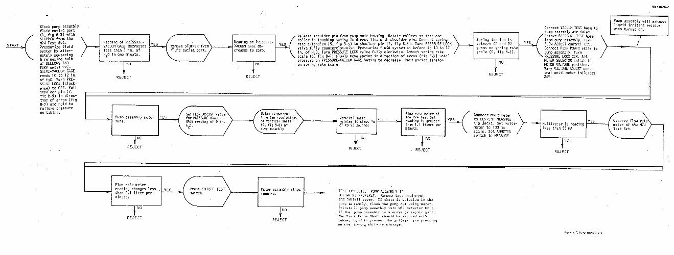
--A
-f-
I-
id